EP2138694A1 - Brennstoffeinspritzvorrichtung - Google Patents
Brennstoffeinspritzvorrichtung Download PDFInfo
- Publication number
- EP2138694A1 EP2138694A1 EP09163827A EP09163827A EP2138694A1 EP 2138694 A1 EP2138694 A1 EP 2138694A1 EP 09163827 A EP09163827 A EP 09163827A EP 09163827 A EP09163827 A EP 09163827A EP 2138694 A1 EP2138694 A1 EP 2138694A1
- Authority
- EP
- European Patent Office
- Prior art keywords
- fuel
- injection
- fuel injection
- pressure
- amount
- Prior art date
- Legal status (The legal status is an assumption and is not a legal conclusion. Google has not performed a legal analysis and makes no representation as to the accuracy of the status listed.)
- Granted
Links
- 239000000446 fuel Substances 0.000 title claims abstract description 2725
- 238000002347 injection Methods 0.000 title claims abstract description 2546
- 239000007924 injection Substances 0.000 title claims abstract description 2545
- 238000011144 upstream manufacturing Methods 0.000 claims abstract description 78
- 238000001514 detection method Methods 0.000 claims description 256
- 230000007423 decrease Effects 0.000 claims description 131
- 238000009825 accumulation Methods 0.000 claims description 99
- 238000002485 combustion reaction Methods 0.000 claims description 96
- 238000000034 method Methods 0.000 claims description 91
- 230000009467 reduction Effects 0.000 claims description 85
- 230000000644 propagated effect Effects 0.000 claims description 27
- 238000001914 filtration Methods 0.000 claims description 25
- 230000006835 compression Effects 0.000 claims description 21
- 238000007906 compression Methods 0.000 claims description 21
- 230000008569 process Effects 0.000 claims description 21
- 238000003860 storage Methods 0.000 claims description 19
- 230000003247 decreasing effect Effects 0.000 claims description 16
- 238000012937 correction Methods 0.000 description 177
- 238000012545 processing Methods 0.000 description 127
- 230000002123 temporal effect Effects 0.000 description 97
- 230000004048 modification Effects 0.000 description 65
- 238000012986 modification Methods 0.000 description 65
- 230000001276 controlling effect Effects 0.000 description 53
- 239000011236 particulate material Substances 0.000 description 37
- 238000004519 manufacturing process Methods 0.000 description 36
- 230000001105 regulatory effect Effects 0.000 description 36
- 230000008901 benefit Effects 0.000 description 27
- 230000003111 delayed effect Effects 0.000 description 27
- 230000010349 pulsation Effects 0.000 description 23
- 230000004044 response Effects 0.000 description 21
- 238000010586 diagram Methods 0.000 description 18
- 230000008859 change Effects 0.000 description 15
- 230000006870 function Effects 0.000 description 15
- 238000006243 chemical reaction Methods 0.000 description 13
- 239000002828 fuel tank Substances 0.000 description 12
- XEEYBQQBJWHFJM-UHFFFAOYSA-N Iron Chemical group [Fe] XEEYBQQBJWHFJM-UHFFFAOYSA-N 0.000 description 11
- 238000004880 explosion Methods 0.000 description 11
- NGBFQHCMQULJNZ-UHFFFAOYSA-N Torsemide Chemical compound CC(C)NC(=O)NS(=O)(=O)C1=CN=CC=C1NC1=CC=CC(C)=C1 NGBFQHCMQULJNZ-UHFFFAOYSA-N 0.000 description 8
- 230000014509 gene expression Effects 0.000 description 7
- 238000005070 sampling Methods 0.000 description 7
- 230000006399 behavior Effects 0.000 description 6
- 238000005520 cutting process Methods 0.000 description 6
- 230000000694 effects Effects 0.000 description 6
- 239000003054 catalyst Substances 0.000 description 5
- 239000003638 chemical reducing agent Substances 0.000 description 5
- 230000001934 delay Effects 0.000 description 5
- 238000002474 experimental method Methods 0.000 description 5
- 238000004891 communication Methods 0.000 description 4
- 238000006731 degradation reaction Methods 0.000 description 4
- 230000000630 rising effect Effects 0.000 description 4
- 230000005856 abnormality Effects 0.000 description 3
- 230000032683 aging Effects 0.000 description 3
- XLYOFNOQVPJJNP-UHFFFAOYSA-N water Substances O XLYOFNOQVPJJNP-UHFFFAOYSA-N 0.000 description 3
- 230000004888 barrier function Effects 0.000 description 2
- 230000007812 deficiency Effects 0.000 description 2
- 239000012530 fluid Substances 0.000 description 2
- 239000007788 liquid Substances 0.000 description 2
- 230000001902 propagating effect Effects 0.000 description 2
- 238000007789 sealing Methods 0.000 description 2
- 229910000851 Alloy steel Inorganic materials 0.000 description 1
- 229910000975 Carbon steel Inorganic materials 0.000 description 1
- 230000002238 attenuated effect Effects 0.000 description 1
- 239000010962 carbon steel Substances 0.000 description 1
- 230000015556 catabolic process Effects 0.000 description 1
- 230000001419 dependent effect Effects 0.000 description 1
- 230000005611 electricity Effects 0.000 description 1
- 238000004904 shortening Methods 0.000 description 1
- 230000006641 stabilisation Effects 0.000 description 1
- 238000011105 stabilization Methods 0.000 description 1
- 230000000087 stabilizing effect Effects 0.000 description 1
- 230000001629 suppression Effects 0.000 description 1
Images


Classifications
-
- F—MECHANICAL ENGINEERING; LIGHTING; HEATING; WEAPONS; BLASTING
- F02—COMBUSTION ENGINES; HOT-GAS OR COMBUSTION-PRODUCT ENGINE PLANTS
- F02D—CONTROLLING COMBUSTION ENGINES
- F02D41/00—Electrical control of supply of combustible mixture or its constituents
- F02D41/30—Controlling fuel injection
- F02D41/38—Controlling fuel injection of the high pressure type
- F02D41/3809—Common rail control systems
-
- F—MECHANICAL ENGINEERING; LIGHTING; HEATING; WEAPONS; BLASTING
- F02—COMBUSTION ENGINES; HOT-GAS OR COMBUSTION-PRODUCT ENGINE PLANTS
- F02M—SUPPLYING COMBUSTION ENGINES IN GENERAL WITH COMBUSTIBLE MIXTURES OR CONSTITUENTS THEREOF
- F02M63/00—Other fuel-injection apparatus having pertinent characteristics not provided for in groups F02M39/00 - F02M57/00 or F02M67/00; Details, component parts, or accessories of fuel-injection apparatus, not provided for in, or of interest apart from, the apparatus of groups F02M39/00 - F02M61/00 or F02M67/00; Combination of fuel pump with other devices, e.g. lubricating oil pump
- F02M63/02—Fuel-injection apparatus having several injectors fed by a common pumping element, or having several pumping elements feeding a common injector; Fuel-injection apparatus having provisions for cutting-out pumps, pumping elements, or injectors; Fuel-injection apparatus having provisions for variably interconnecting pumping elements and injectors alternatively
- F02M63/0225—Fuel-injection apparatus having a common rail feeding several injectors ; Means for varying pressure in common rails; Pumps feeding common rails
-
- F—MECHANICAL ENGINEERING; LIGHTING; HEATING; WEAPONS; BLASTING
- F02—COMBUSTION ENGINES; HOT-GAS OR COMBUSTION-PRODUCT ENGINE PLANTS
- F02D—CONTROLLING COMBUSTION ENGINES
- F02D2200/00—Input parameters for engine control
- F02D2200/02—Input parameters for engine control the parameters being related to the engine
- F02D2200/06—Fuel or fuel supply system parameters
- F02D2200/0602—Fuel pressure
-
- F—MECHANICAL ENGINEERING; LIGHTING; HEATING; WEAPONS; BLASTING
- F02—COMBUSTION ENGINES; HOT-GAS OR COMBUSTION-PRODUCT ENGINE PLANTS
- F02D—CONTROLLING COMBUSTION ENGINES
- F02D2200/00—Input parameters for engine control
- F02D2200/02—Input parameters for engine control the parameters being related to the engine
- F02D2200/06—Fuel or fuel supply system parameters
- F02D2200/0614—Actual fuel mass or fuel injection amount
- F02D2200/0616—Actual fuel mass or fuel injection amount determined by estimation
-
- F—MECHANICAL ENGINEERING; LIGHTING; HEATING; WEAPONS; BLASTING
- F02—COMBUSTION ENGINES; HOT-GAS OR COMBUSTION-PRODUCT ENGINE PLANTS
- F02D—CONTROLLING COMBUSTION ENGINES
- F02D2250/00—Engine control related to specific problems or objectives
- F02D2250/04—Fuel pressure pulsation in common rails
-
- F—MECHANICAL ENGINEERING; LIGHTING; HEATING; WEAPONS; BLASTING
- F02—COMBUSTION ENGINES; HOT-GAS OR COMBUSTION-PRODUCT ENGINE PLANTS
- F02D—CONTROLLING COMBUSTION ENGINES
- F02D41/00—Electrical control of supply of combustible mixture or its constituents
- F02D41/008—Controlling each cylinder individually
-
- F—MECHANICAL ENGINEERING; LIGHTING; HEATING; WEAPONS; BLASTING
- F02—COMBUSTION ENGINES; HOT-GAS OR COMBUSTION-PRODUCT ENGINE PLANTS
- F02D—CONTROLLING COMBUSTION ENGINES
- F02D41/00—Electrical control of supply of combustible mixture or its constituents
- F02D41/30—Controlling fuel injection
- F02D41/38—Controlling fuel injection of the high pressure type
- F02D41/40—Controlling fuel injection of the high pressure type with means for controlling injection timing or duration
- F02D41/402—Multiple injections
-
- F—MECHANICAL ENGINEERING; LIGHTING; HEATING; WEAPONS; BLASTING
- F02—COMBUSTION ENGINES; HOT-GAS OR COMBUSTION-PRODUCT ENGINE PLANTS
- F02M—SUPPLYING COMBUSTION ENGINES IN GENERAL WITH COMBUSTIBLE MIXTURES OR CONSTITUENTS THEREOF
- F02M2200/00—Details of fuel-injection apparatus, not otherwise provided for
- F02M2200/24—Fuel-injection apparatus with sensors
-
- F—MECHANICAL ENGINEERING; LIGHTING; HEATING; WEAPONS; BLASTING
- F02—COMBUSTION ENGINES; HOT-GAS OR COMBUSTION-PRODUCT ENGINE PLANTS
- F02M—SUPPLYING COMBUSTION ENGINES IN GENERAL WITH COMBUSTIBLE MIXTURES OR CONSTITUENTS THEREOF
- F02M2200/00—Details of fuel-injection apparatus, not otherwise provided for
- F02M2200/28—Details of throttles in fuel-injection apparatus
-
- F—MECHANICAL ENGINEERING; LIGHTING; HEATING; WEAPONS; BLASTING
- F02—COMBUSTION ENGINES; HOT-GAS OR COMBUSTION-PRODUCT ENGINE PLANTS
- F02M—SUPPLYING COMBUSTION ENGINES IN GENERAL WITH COMBUSTIBLE MIXTURES OR CONSTITUENTS THEREOF
- F02M2200/00—Details of fuel-injection apparatus, not otherwise provided for
- F02M2200/31—Fuel-injection apparatus having hydraulic pressure fluctuations damping elements
- F02M2200/315—Fuel-injection apparatus having hydraulic pressure fluctuations damping elements for damping fuel pressure fluctuations
Definitions
- the present invention relates to a fuel injection device which feeds fuel accumulated in a fuel accumulation part in a pressure-accumulated state to each cylinder of an internal combustion engine from a fuel injector.
- an engine controlling device calculates a fuel injection amount based on an operating condition of a vehicle, such as an engine rotation speed and an accelerator opening, which corresponds to the depression of an accelerator pedal, and outputs an injection command signal indicating the fuel injection amount to a fuel injector of each cylinder to inject fuel.
- an operating condition of a vehicle such as an engine rotation speed and an accelerator opening, which corresponds to the depression of an accelerator pedal
- an injection command signal indicating the fuel injection amount to a fuel injector of each cylinder to inject fuel.
- the lift amount of a nozzle needle in the fuel injector or the area of a fuel injection port is varied due to manufacturing tolerance of the fuel injector, which varies the fuel injection amount.
- the air intake amount or dimension of each cylinder is also varied. Because of these factors, even if fuel injection signals which have the same wave forms are output to the fuel injector of each cylinder, there are variations in the generated torque among the cylinders.
- the variations of the generated torque among the cylinders may be detected based on variations in the engine rotation angle speed or the crank angle speed.
- the variations of the generated torque which is the combined result of factors such as those described above, are left unchanged, and the injection command signal to a fuel injector is modified to suppress the variations of the generated torque.
- Japanese Patent Publication No. 2003-184632 ( Figs. 4 and 12 , and [0051] to [0058]) discloses a fuel injection device which includes a fuel accumulation part for accumulating fuel delivered by a fuel pump in a pressure-accumulated state, a fuel injection valve for supplying to each cylinder of an internal combustion engine fuel which is supplied through a fuel supply passage branched from the fuel accumulation part, and a control unit which outputs an injection command signal for injecting thee fuel from the fuel injection valve.
- the fuel injection device further includes a differential pressure sensor for detecting the pressure difference at a venturi constriction provided in the fuel supply passage, and the control unit calculates the fuel supply amount which passes through the venturi constriction based on the signal from the differential pressure sensor.
- Japnese Patent No. 3542211 discloses a fuel injection device which includes a fuel accumulation part for accumulating fuel delivered by a fuel pump in a pressure-accumulated state, a fuel injection valve for supplying to each cylinder of an internal combustion engine fuel which is supplied through a fuel supply passage branched from the fuel accumulation part, and a control unit which outputs an injection command signal for injecting the fuel from the fuel injection valve.
- the fuel injection device further includes an orifice in the vicinity of an end of the fuel supply passage on the side of the fuel accumulation part. The fuel injection device suppresses pulsations of the pressure of the fuel accumulation part by changing the opening diameter of the orifice, depending on the capacities of the fuel accumulation part and fuel supply passages for distributing fuel in each cylinder.
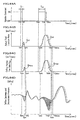
- a technique for multi-injection which divides fuel injection from the fuel injection valve into separate phases. For example, a Pilot fuel injection is performed when a piston well advances from TDC (Top Dead Center) (during a compression stroke), and a Main fuel injection is performed around TDC in the technique.
- TDC Top Dead Center
- a Main fuel injection is performed around TDC in the technique.
- the fuel injection amount of the latter fuel injection can not be controlled accurately since the pressure of the fuel accumulation part at the time when the latter fuel injection starts is affected by the pressure fluctuations (pulsation wave is generated) caused by the former fuel injection.
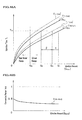
- the pressure of a high pressure fuel supply passage at the time when the Main fuel injection starts after the Pilot fuel injection is performed is significantly varied among the three cases A, B, C as shown in Fig. 85B .
- the pressure difference between the pressure behavior curves of the case A and the case C at the time when the Main fuel injection starts is 10MPa. Therefore, it is obvious that the actual injection amounts differ between the two cases if the time for which the Main fuel injection is performed is the same.
- the pressure behavior curve of the case D in Fig. 85B is a pressure behavior curve when only the Pilot fuel injection is performed.
- Japnese Patent No. 3803521 estimates the pressure variation of the fuel accumulation part caused by the former fuel injection based on experimental data which has been obtained in advance.
- 3803521 obtains effects of the pressure amplitude of the pulsation waves based on the injection time of the Pilot fuel injection, effects of the phase of the pulsation waves based on the time from the injection finishing timing of the Pilot fuel injection to the injection start timing of the Main fuel injection, the injection time of the Main fuel injection which has not been corrected, and a factor for modifying a pressure variation correction amount based on fuel temperature, and corrects the injection time of the Main fuel injection based on the effects of the pressure amplitude of the pulsation waves, effects of the phase of the pulsation waves and the factor for modifying a pressure variation correction amount.
- the actual fuel injection amount is still varied due to manufacturing tolerance of the fuel injection valve. More specifically, even if a target fuel injection amount is determined based on an engine rotation speed and an accelerator opening, a target pilot fuel injection amount of the Pilot fuel injection is determined, and a target main fuel injection amount is determined to be the amount obtained by subtracting the target pilot fuel injection amount from the target fuel injection amount, actual fuel injection is not performed in accordance with the target pilot fuel injection amount and target main fuel injection amount due to manufacturing tolerance of the fuel injection valve, which makes the actual fuel injection amount to be different from the target fuel injection amount. Furthermore, the actual fuel injection amount becomes different from the target main fuel injection amount because of the estimation error of the pressure variation in the fuel accumulation part caused by the pressure variation of the Pilot fuel injection.
- the present invention has been made in view of the above problems, and an object thereof is to provide a fuel injection device that enables to accurately calculate a fuel injection amount which is actually injected and to more precisely inject fuel in accordance with a target fuel injection amount.
- a first aspect of the present invention is to provide a fuel injection device including: a fuel accumulation part for accumulating fuel delivered by a fuel pump in a pressure-accumulated state; a fuel injection valve for supplying to a combustion chamber of a cylinder of an internal combustion engine the fuel which is supplied through one of a plurality of fuel supply passages branched from the fuel accumulation part to cylinders; a control unit which outputs an injection command signal for injecting the fuel from the fuel injection valve; an orifice provided in the fuel supply passage; and a differential pressure sensor for detecting a pressure difference between upstream and downstream sides of the orifice provided in the supply passages; the control unit calculating an actual fuel supply amount which passes the orifice based on a signal from the differential pressure sensor.
- a second aspect of the present invention provides a fuel injection device including: a fuel accumulation part for accumulating fuel delivered by a fuel pump in a pressure-accumulated state; a fuel injection valve for supplying to a combustion chamber of a cylinder of an internal combustion engine the fuel which is supplied through one of a plurality of fuel supply passages branched from the fuel accumulation part to cylinders; a control unit which outputs an injection command signal for injecting the fuel from the fuel injection valve; an accumulation part pressure sensor for detecting a pressure of the fuel accumulation part; an orifice provided in the fuel supply passage; and a fuel supply passage pressure sensor for detecting a pressure on a downstream side of the orifice provided in the fuel supply passage, the control unit calculating an actual fuel supply amount which passes the orifice by calculating a pressure difference between upstream and downstream sides of the orifice based on signals from the accumulation part pressure sensor and the fuel supply passage pressure sensor.
- a third aspect of the present invention provides a fuel injection device including: a fuel accumulation part for accumulating fuel delivered by a fuel pump in a pressure-accumulated state; a fuel injection valve for supplying to a combustion chamber of a cylinder of an internal combustion engine the fuel which is supplied through one of a plurality of fuel supply passages branched from the fuel accumulation part to cylinders; a control unit which outputs an injection command signal for injecting the fuel from the fuel injection valve; an orifice provided in the fuel supply passage; and a fuel supply passage pressure sensor for detecting a pressure on a downstream side of the orifice provided in the fuel supply passage, the control unit detecting an amount of pressure decrease on the downstream side of the orifice caused by fuel injection from the fuel injection valve based on a signal from the fuel supply passage pressure sensor and calculating an actual fuel supply amount which passes the orifice based on the detected amount of the pressure decrease.
- control unit may calculate the actual fuel supply amount based on the amount of the pressure decrease during a period from a first timing at which the pressure decrease on the downstream side of the orifice is detected after a rise of the injection command signal for the fuel injection valve to a second timing at which the pressure on the downstream side of the orifice becomes equal to or more than a predetermined value after the first timing.
- the control unit may store in advance data of a reference pressure reduction line of which value is simply decreased as the time lapses, obtain a first timing at which the pressure on the downstream side of the orifice is decreased to be equal to or less than a threshold value after a rise of the injection command signal for the fuel injection valve, obtain the pressure on the downstream side of the orifice at the first timing, set the reference pressure reduction line by taking the pressure on the downstream side of the orifice at the first timing as an initial value of the reference pressure reduction line, obtain a second timing at which the pressure on the downstream side of the orifice is increased to be equal to or more than the set reference pressure reduction line after the first timing, and calculate the actual fuel supply amount based on the amount of the pressure decrease during a period from the first timing to the second timing.
- control unit may filtering processe the signal from the fuel supply passage pressure sensor to remove a high frequency component, and detect the pressure decrease on the downstream side of the orifice based on the signal from which the high frequency component has been removed by the filtering-process.
- a volume of a fuel passage from the orifice provided in the fuel supply passage to a fuel injection port of the fuel injection valve of the cylinder may be designed to be greater than the maximum actual fuel supply amount which is supplied at one time for the fuel injection valve.
- the fuel injection valve may supply all amount of fuel which is supplied through the fuel supply passage to the combustion chamber of the cylinder at the time of fuel injection, and the control unit calculates the actual fuel supply amount which passes the orifice as an actual fuel injection amount which is actually injected to the cylinder and controls the fuel injection based on the actual fuel injection amount.
- the fuel injection valve may return a part of the fuel which has been supplied through the fuel supply passage to a return fuel pipe to discharge the fuel to a low pressure part of a fuel supply system at the time of fuel injection, and the control unit may calculate, from the actual fuel supply amount that passes the orifice, an actual fuel injection amount which is actually supplied to the combustion chamber of the cylinder without returning to the return fuel pipe based on the actual fuel supply amount and a predetermined coefficient value, and controls the fuel injection based on the calculated actual fuel injection amount.
- control unit may store in advance the predetermined coefficient values that are associated with at least patterns of the injection command signal, and set an appropriate coefficient value from the stored predetermined coefficient values with reference to at least the patterns of the injection command signal.
- At least one of the plurality of fuel supply passages may include an orifice and a fuel supply passage pressure sensor for detecting the pressure on the downstream side of the orifice and constitutes a first fuel supply passage for supplying the fuel to a first cylinder through the fuel injection valve, and another fuel supply passage among the plurality of the fuel supply passages other than the first fuel supply passage includes an orifice and constitutes a second fuel supply passage for supplying the fuel to a second cylinder through the fuel injection valve, and the control unit may: calculate a pressure difference between upstream and downstream sides of the orifice in the first fuel supply passage based on signals from the accumulation part pressure sensor and the fuel supply passage pressure sensor; calculate an actual fuel supply amount to the fuel injection valve of the first cylinder through the first fuel supply passage by using the calculated pressure difference; detect, with the fuel supply passage pressure sensor, a pressure variation which is generated in the second fuel supply passage by supplying the fuel to the fuel injection valve of the second cylinder through the second fuel supply passage and is propagated to the downstream side
- At least one of the plurality of fuel supply passages may include an orifice and a fuel supply passage pressure sensor for detecting the pressure on the downstream side of the orifice and constitutes a first fuel supply passage for supplying the fuel to a first cylinder through the fuel injection valve, and another fuel supply passage among the plurality of the fuel supply passages other than the first fuel supply passage includes an orifice and constitutes a second fuel supply passage for supplying the fuel to a second cylinder through the fuel injection valve, and the control unit: calculates an amount of pressure decrease on a downstream side of the orifice in the first fuel supply passage based on the signal from the fuel supply passage pressure sensor; calculates an actual fuel supply amount to the fuel injection valve of the first cylinder through the first fuel supply passage by using the calculated amount of the pressure decrease; detects, with the fuel supply passage pressure sensor, a pressure variation which is generated in the second fuel supply passage by supplying the fuel to the fuel injection valve of the second cylinder through the second fuel supply passage and is propagated to the downstream side
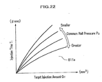
- the aforementioned fuel injection device may further include an accumulation part pressure sensor for detecting a pressure of the fuel accumulation part and a storage unit for storing data of a Ti-Q characteristic which represents a correlation of a fuel injection amount (Q inject ) from the fuel injection valve and an injection time (T i ), wherein the fuel injection valve supplies all amount of fuel which is supplied through the fuel supply passage to the combustion chamber of the cylinder at the time of fuel injection, and the Ti-Q characteristic is represented as a characteristic curve which is represented as a polynomial equation obtained by regression analyzing data discretely measuring the correlation of the fuel injection amount (Q inject ) and the injection time (T i ) at a representative pressure value representing the pressure of the fuel accumulation part, and wherein the control unit sets a target injection amount of fuel to be injected from the fuel injection valve; obtains a target injection time that corresponds to the target injection amount with reference to the characteristic curve based on the pressure of the fuel accumulation part detected by the accumulation part pressure sensor and the target injection amount; calculates an actual fuel injection amount which
- the aforementioned fuel injection device may further include a storage unit for storing data of a Ti-Q characteristic which represents a correlation of a fuel injection amount (Q inject ) from the fuel injection valve and an injection time (T i ), wherein the fuel injection valve supplies all amount of fuel which is supplied through the fuel supply passage to the combustion chamber of the cylinder at the time of fuel injection, and the Ti-Q characteristic is represented as a characteristic curve which is represented as a polynomial equation obtained by regression analyzing data discretely measuring the correlation of the fuel injection amount (Q inject ) and the injection time (T i ) at a representative pressure value representing the pressure of the fuel accumulation part, and wherein the control unit sets a target injection amount of fuel to be injected from the fuel injection valve; obtains a target injection time that corresponds to the target injection amount with reference to the characteristic curve based on the pressure of the fuel accumulation part detected by the accumulation part pressure sensor and the target injection amount; calculates a pressure difference between upstream and downstream sides of the orifice based on signals from the accumulation part
- the aforementioned fuel injection device may further include an accumulation part pressure sensor for detecting a pressure of the fuel accumulation part and a storage unit for storing data of a Ti-Q characteristic which represents a correlation of a fuel injection amount (Q inject ) from the fuel injection valve and an injection time (T i ), wherein the fuel injection valve supplies a total amount of fuel which is supplied through the fuel supply passage to the combustion chamber of the cylinder at the time of fuel injection, and the Ti-Q characteristic is represented as a characteristic curve which is represented as a polynomial equation obtained by regression analyzing data discretely measuring the correlation of the fuel injection amount (Q inject ) and the injection time (T i ) at a representative pressure value representing the pressure of the fuel accumulation part, and wherein the control unit sets a target injection amount of fuel to be injected from the fuel injection valve; obtains a target injection time that corresponds to the target injection amount with reference to the characteristic curve based on the pressure of the fuel accumulation part detected by the accumulation part pressure sensor and the target injection amount, detects the amount of the
- the aforementioned fuel injection device may further include an accumulation part pressure sensor for detecting a pressure of the fuel accumulation part and a storage unit for storing data of a Ti-Q characteristic which represents a correlation of a fuel injection amount (Q inject ) from the fuel injection valve and an injection time (T i ), wherein the fuel injection valve returns a part of the fuel which has been supplied through the fuel supply passage to a return fuel pipe to discharge the fuel to a low pressure part of a fuel supply system at the time of fuel injection, and the Ti-Q characteristic is represented as a characteristic curve which is represented as a polynomial equation obtained by regression analyzing data discretely measuring the correlation of the fuel injection amount (Q inject ) and the injection time (T i ) at a representative pressure value representing the pressure of the fuel accumulation part, and wherein the control unit sets a target injection amount of fuel to be injected from the fuel injection valve; obtains a target injection time that corresponds to the target injection amount with reference to the characteristic curve based on the pressure of the fuel accumulation part detected by the accumulation
- the aforementioned fuel injection device may further include a storage unit for storing data of a Ti-Q characteristic which represents a correlation of a fuel injection amount (Q inject ) from the fuel injection valve and an injection time (T i ), wherein the fuel injection valve returns a part of the fuel which has been supplied through the fuel supply passage to a return fuel pipe to discharge the fuel to a low pressure part of a fuel supply system at the time of fuel injection, and the Ti-Q characteristic is represented as a characteristic curve which is represented as a polynomial equation obtained by regression analyzing data discretely measuring the correlation of the fuel injection amount (Q inject ) and the injection time (T i ) at a representative pressure value representing the pressure of the fuel accumulation part, and wherein the control unit sets a target injection amount of fuel to be injected from the fuel injection valve; obtains a target injection time that corresponds to the target injection amount with reference to the characteristic curve based on the pressure of the fuel accumulation part detected by the accumulation part pressure sensor and the target injection amount; calculates a pressure difference between up
- the aforementioned fuel injection device may further include an accumulation part pressure sensor for detecting a pressure of the fuel accumulation part and a storage unit for storing data of a Ti-Q characteristic which represents a correlation of a fuel injection amount (Q inject ) from the fuel injection valve and an injection time (T i ), wherein the fuel injection valve returns a part of the fuel which has been supplied through the fuel supply passage to a return fuel pipe to discharge the fuel to a low pressure part of a fuel supply system at the time of fuel injection, and the Ti-Q characteristic is represented as a characteristic curve which is represented as a polynomial equation obtained by regression analyzing data discretely measuring the correlation of the fuel injection amount (Q inject ) and the injection time (T i ) at a representative pressure value representing the pressure of the fuel accumulation part, and wherein the control unit sets a target injection amount of fuel to be injected from the fuel injection valve; obtains a target injection time that corresponds to the target injection amount with reference to the characteristic curve based on the pressure of the fuel accumulation part detected by the accumulation
- the fuel injection valve supplies all amount of fuel which is supplied through the fuel supply passage to the combustion chamber of the cylinder at the time of fuel injection
- the control unit sets the injection command signal for injecting the fuel from the fuel injection valve based on an operation condition of the internal combustion engine; includes an actual fuel supply information detection unit for determining, based on the injection command signal, fuel injection information that includes at least an injection start timing and an injection finishing timing of the fuel injection valve, performing during a compression stroke or an expansion stroke of the cylinder of the internal combustion engine a multi-injection in which the fuel injection from the fuel injection valve is divided into a plurality of times of fuel injections, and for detecting actual fuel supply information on the fuel that has passed the orifice based on the signal from the differential pressure sensor, and an actual fuel injection information detection unit for detecting actual fuel injection information based on the detected actual fuel supply information; and determines the fuel injection information on a subsequent fuel injection that is performed later than a preceding fuel injection based on the actual fuel injection information of the preceding fuel
- the fuel injection valve supplies all amount of fuel which is supplied through the fuel supply passage to the combustion chamber of the cylinder at the time of fuel injection
- the control unit sets the injection command signal for injecting the fuel from the fuel injection valve based on an operation condition of the internal combustion engine; includes an actual fuel supply information detection unit for determining, based on the injection command signal, fuel injection information that includes at least an injection start timing and an injection finishing timing of the fuel injection valve, performing during a compression stroke or an expansion stroke of the cylinder of the internal combustion engine a multi-injection in which the fuel injection from the fuel injection valve is divided into a plurality of times of fuel injections, and for detecting the amount of the pressure decrease on the downstream side of the orifice caused by the fuel injection from the fuel injection valve based on the signal from the fuel supply passage pressure sensor, and calculates an actual fuel supply information on the fuel that has passed the orifice based on the amount of the pressure decrease, and an actual fuel injection information detection unit for detecting actual fuel injection information based on the detected actual
- the fuel injection valve returns, as a back flow, a part of the fuel which has been supplied through the fuel supply passage to a return fuel pipe to discharge the fuel to a low pressure part of a fuel supply system at the time of fuel injection
- the control unit sets the injection command signal for injecting the fuel from the fuel injection valve based on an operation condition of the internal combustion engine; includes an actual fuel supply information detection unit for determining, based on the injection command signal, fuel injection information that includes at least an injection start timing and an injection finishing timing of the fuel injection valve, performing during a compression stroke or an expansion stroke of the cylinder of the internal combustion engine a multi-injection in which the fuel injection from the fuel injection valve is divided into a plurality of times of fuel injections, and for detecting actual fuel supply information on the fuel that has passed the orifice based on the signal from the differential pressure sensor, and an actual fuel injection information detection unit for detecting actual fuel injection information based on the detected actual fuel supply information and back flow information on the back flow which is stored in advance;
- the fuel injection valve returns, as a back flow, a part of the fuel which has been supplied through the fuel supply passage to a return fuel pipe to discharge the fuel to a low pressure part of a fuel supply system at the time of fuel injection
- the control unit sets the injection command signal for injecting the fuel from the fuel injection valve based on an operation condition of the internal combustion engine; includes an actual fuel supply information detection unit for determining, based on the injection command signal, fuel injection information that includes at least an injection start timing and an injection finishing timing of the fuel injection valve, performing during a compression stroke or an expansion stroke of the cylinder of the internal combustion engine a multi-injection in which the fuel injection from the fuel injection valve is divided into a plurality of times of fuel injections, and for detecting actual fuel supply information on the fuel that has passed the orifice based on the signals from the accumulation part pressure sensor and the fuel supply passage pressure sensor, and an actual fuel injection information detection unit for detecting actual fuel injection information based on the detected actual fuel supply information and back flow information on the
- the fuel injection valve returns, as a back flow, a part of the fuel which has been supplied through the fuel supply passage to a return fuel pipe to discharge the fuel to a low pressure part of a fuel supply system at the time of fuel injection
- the control unit sets the injection command signal for injecting the fuel from the fuel injection valve based on an operation condition of the internal combustion engine; includes an actual fuel supply information detection unit for determining, based on the injection command signal, fuel injection information that includes at least an injection start timing and an injection finishing timing of the fuel injection valve, performing during a compression stroke or an expansion stroke of the cylinder of the internal combustion engine a multi-injection in which the fuel injection from the fuel injection valve is divided into a plurality of times of fuel injections, and for detecting the amount of the pressure decrease on the downstream side of the orifice caused by the fuel injection from the fuel injection valve based on the signal from the fuel supply passage pressure sensor, and calculates an actual fuel supply information on the fuel that has passed the orifice based on the amount of the
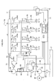
- a fuel injection device according to a first embodiment of the present invention is described in detail below with reference to Figs. 1 and 2 .
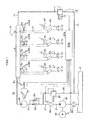
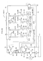
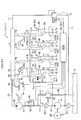
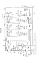
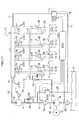
- Fig. 1 is an illustration showing an entire configuration of an accumulator fuel injection device according to a first embodiment of the present invention.
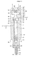
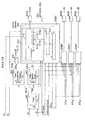
- Fig. 2 is an illustration for showing a conceptual configuration of a direct acting fuel injection valve (injector) used in the accumulator fuel injection device according to the first embodiment.
- a fuel injection device 1A includes: a low pressure pump 3A (also called as a feed pump) driven by a motor 63 which is electronically controlled by an engine controlling device (control unit) 80A (hereinafter referred to as an ECU 80A) ; a high pressure pump 3B (also called as a supply pump) mechanically driven by driving force taken out from the engine crank shaft; a common rail (fuel accumulation part) 4 to which high pressure fuel is supplied from the high pressure pump 3B; an injector (fuel injection valve) 5A for injecting the high pressure fuel into a combustion chamber of an internal combustion engine, such as 4 cylinder diesel engine (hereinafter referred to as an engine); and an actuator 6A incorporated in the injector 5A which is electronically controlled by the ECU 80A.
- a low pressure pump 3A also called as a feed pump driven by a motor 63 which is electronically controlled by an engine controlling device (control unit) 80A (hereinafter referred to as an ECU 80A)
- a high pressure pump 3B also called as a supply
- the low pressure pump 3A and the high pressure pump 3B are also referred to as a fuel pump.
- a fuel injection amount, a target fuel injection amount, and an actual fuel injection amount are called an “injection amount” , a “target injection amount”, and an “actual injection amount” , respectively.
- the ECU 80A includes a micro computer, an interface circuit, and an actuator driving circuit for driving the actuator 6A though they are not shown in Fig. 1 .
- the micro computer electronically controls the actuator 6A by calculating an optimum fuel injection amount and an optimum injection timing based on signals from various sensors such as, an engine rotation speed sensor, a cylinder discriminating sensor, a crank angle sensor, a water temperature sensor, an intake air temperature sensor, an intake air pressure sensor, an accelerator (throttle) opening sensor, a fuel temperature sensor S Tf , a pressure sensor (accumulation part pressure sensor) S Pc , and a differential pressure sensor S dP .
- the ECU 80A may include a motor driving circuit for driving the motor 63, or the motor driving circuit may be provided outside of the ECU 80A.
- the low pressure pump 3A and the motor 63 are incorporated in a fuel tank 2 together with a filter 62.
- the low pressure pump 3A and the motor 63 supplies fuel to the intake side of the high pressure pump 3B from the fuel tank 2 through the low pressure fuel supply passage 61.
- a strainer 64A and a flow regulating valve 69 incorporating a check valve 68 are arranged in series in the low pressure fuel supply passage 61 from the discharge side of the low pressure pump 3A to the intake side of the high pressure pump 3B.
- the strainer 64 includes a differential pressure sensor (not shown), and the signal of the differential pressure sensor is input to the ECU 80A so as to allow the ECU 80A to detect abnormalities of the low pressure pump 3A, the filter 62 and the strainer 64 (e. g. decrease in a low pressure fuel supply amount).
- a return piping 65 which branches from a middle of the strainer 64 and the flow regulating valve 69 of the low pressure fuel supply passage 61 returns the excessive amount of fuel supply from the low pressure pump 3A to the fuel tank 2 via a pressure regulating valve 67.
- the high pressure pump 3B is provided with a fuel temperature sensor S Tf which detects the temperature of fuel to be discharged, and the signal of the fuel temperature sensor S Tf is output to the ECU 80A.
- the high pressure fuel that is discharged from the high pressure pump 3B to a discharge piping 70 is accumulated in the common rail 4, which is a kind of a surge tank for accumulating comparatively high pressure fuel.
- the common rail 4 is provided with a pressure sensor S Pc for detecting the pressure Pc of the common rail 4 (hereinafter also referred to as a common rail pressure Pc).
- the detection signal from the pressure sensor S Pc is output to the ECU 80A, and the ECU 80A controls the pressure of the common rail 4 to be a predetermined target pressure of from 30 MPa to 200 MPa in response to an operating condition of a vehicle, such as an engine rotation speed, by adjusting a pressure control valve 72 arranged in a return piping 71 which connects the common rail 4 and the fuel tank 2.
- the common rail 4 is configured to be communicated with the injectors 5A through high pressure fuel supply passages (fuel supply passages) 21.
- An orifice 75 is provided to the common rail 4 side of each of the four high pressure fuel supply passages 21.
- Pressure detection pipes which are respectively taken from the upstream side of the orifice 75 (the common rail 4 side) and the downstream side (the side far from the common rail 4) are connected to the differential pressure sensor S dP .
- the differential pressure sensors S dP detect the orifice differential pressures of the four high pressure fuel supply passages 21, respectively, whereby the fuel flow amount which has passed the orifice 75 of each pressure fuel supply passages 21 can be detected.
- the volume of a fuel passage including the high pressure fuel supply passage 21 that is lower than the orifice 75 and the fuel passage to a fuel injection port 10 inside the injector 5A is designed to exceed the maximum actual fuel supply amount which is supplied through the high pressure fuel supply passage 21 for an explosion stroke among the cycles of aspiration, compression, explosion and exhaust in one cylinder, such as the maximum actual fuel supply amount required when the maximum torque is required by a fully-opened accelerator.
- the maximum actual fuel supply amount means summation of the fuel supply amount of each injection in the case of multi-injection.
- the length of the high pressure fuel supply passages 21 to the injectors 5A of the cylinders of the engine is varied, and thus the position of the orifice 75 in the high pressure fuel supply passage 21 is determined in such a manner that the volume of each fuel passage including the high pressure fuel supply passage 21 that is lower than the orifice 75 and the fuel passage to the fuel injection port 10 inside the injector 5A is the same among cylinders with the enough volume of the fuel passage ensured as described above.
- the injector 5A is attached to each cylinder.
- the injector 5A includes an injector body 13 of which distal end has one or more fuel injection ports 10, a nozzle needle 14 which is slidably supported in the injector body 13, and a piston 16 which is connected to the upper side of the nozzle needle 14 to be integrally reciprocated and displaced with the nozzle needle 14.
- the injector body 13 includes a nozzle body 17, a nozzle holder 19 and an actuator body 55.
- the oil reservoir 20 is formed inside of the nozzle body 17 so as to fill high pressure fuel around the nozzle needle 14.
- the oil reservoir 20 is always communicated with the common rail 4 via the fuel passage 25 and the high pressure fuel supply passage 21.
- the nozzle body 17 is fastened to the nozzle holder 19 with a retaining nut 22.
- the nozzle holder 19 constitutes a cylinder which forms a long hole 23 in the longitudinal direction at its center part.
- the long hole 23 slidably supports the piston 16.
- the operating chamber 56 which is provided to the actuator body 55. The diameter of the operating chamber 56 is larger than that of the long hole 23.
- the nozzle needle 14 is disposed at the same axial center as the center axis of the actuator 6A, and is slidably supported in the inner circumference of the nozzle body 17.
- the nozzle needle 14 is lifted to form a fuel passage between the distal end of the nozzle needle 14 and the nozzle body 17.
- the fuel passage communicates the oil reservoir 20 with the fuel injection port 10 so that fuel is injected to the engine.
- the distal end of the nozzle needle 14 is seated on a seat surface 17a of the nozzle body 17 so that the injection of the high pressure fuel is finished.
- the actuator 6A includes: the actuator body 55 which is fastened to the upper end of the nozzle holder 19 of the injector 5A with a retaining nut 31 in a state where the actuator body 55 and the nozzle holder 19 liquid tightly come in contact with each other; an iron core 33 which is provided inside of the actuator body 55; an electromagnetic coil 34 wound around a housing part of the iron core 33; an operating chamber 56 which is provided in the actuator body 55 and of which diameter is larger than that of the long hole 23; a piston flange part 16a which is provided at the upper end of the piston 16; a stopper 36 for regulating the maximum lift amount of a piston flange part 16a; and a coil spring 37 for biasing the piston 16 in the valve closing direction.
- a connector (not shown) for supplying electricity to the electromagnetic coil 34.
- the iron core 33 is magnetized to be an electric magnet when the electromagnetic coil 34 is energized.
- the iron core 33 attracts the piston flange part 16a upward, and the nozzle needle 14 which is coupled to the piston 16 is moved upward, whereby fuel is injected from the fuel injection port 10.
- a method performed by the ECU 80A for calculating an actual injection amount of fuel to each cylinder is described with reference to Figs. 1 to 3D .
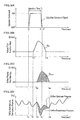
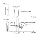
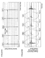
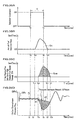
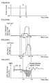
- Figs. 3A to 3D are graphs showing an output pattern of the injection command signal for one cylinder and the temporal variations of fuel flow in the high pressure fuel supply passage.
- Fig. 3A is a graph for showing an output pattern of the injection command signal for one cylinder.
- Fig. 3B is a graph for showing the temporal variation of an actual fuel injection rate of an injector.
- Fig. 3C is a graph for showing the orifice passing flow rate of fuel.
- Fig. 3D is a graph for showing the temporal variation of the pressure in the upstream and the downstream of the orifice.
- the injection command signal of fuel is conceptually represented as a wide pulse.
- the timing when the injection command signal starts to rise is represented as “t S " .
- the timing when the injection command signal starts to fall is represented as “t E "
- the timing when the injection command signal has completed falling is represented as "t E ' " .
- the injection command signal is, for example, an electric power which is output from the ECU 80A to be supplied to the electromagnetic coil 34 provided to the actuator 6A of the injector 5A, and is controlled to be ON or OFF by the ECU 80A.
- the injector 5A (see Fig. 1 ) injects fuel from the fuel injection port 10 only when the injection command signal is ON.
- the ECU 80A is allowed to control the total amount of fuel to be injected (actual injection amount Q A ) from the fuel injection port 10 of the injector 5A by controlling the time for which the injection command signal is ON (injection time T i ).
- the injection command signal has a rising characteristic that the injection command signal rises by a predetermined inclination from the injection start instruction timing t S .
- the injection command signal has a falling characteristic that the injection command signal falls by a predetermined inclination from the injection finish instruction timing t E.
- the ECU 80A is configured to take the rising and falling characteristics into consideration when controlling the injection command signal.
- the injector 5A which is a direct acting fuel injection valve starts to inject fuel at the timing t S1 , which is delayed a little from the fuel injection start instruction timing t S , and completes injection at the timing t E1 , which is delayed a little from the injection finish instruction timing t E as shown in Fig. 3B .
- the flow rate of the fuel which passes the orifice 75 rises at the timing t S2 , which is delayed a little from the timing t S1 by the volume of the fuel passage 25 (see Fig. 2 ) and the high pressure fuel supply passage 21 (see Fig. 1 ) as shown in Fig. 3C .
- the orifice passing flow rate Q OR returns to 0 at the timing t E2 which is delayed from the timing t E1 by the volume of the fuel passage 25 and the high pressure fuel supply passage 21 as shown in Fig.3C .
- the delays of the timings t S1 and t S2 from the injection start instruction timing t S and the delays of the timings t E1 and t E2 from the injection finish instruction timing t E are specific to the injection device 1A, and thus the delays can be obtained in advance by experiments. Therefore, the ECU 80A can take these delays into consideration when controlling the fuel injection device 1A, which allows to control the fuel injection device 1A without being affected by these delays.
- the orifice differential pressure ⁇ P OR can be detected by the differential pressure sensor S dP even if the pressure on the upstream side of the orifice is varied by the variation of the common rail pressure Pc as shown in Fig. 3D , which allows the ECU 80A to accurately calculate the orifice passing flow rate Q OR .
- An orifice passing flow amount (actual fuel supply amount) Q sum which corresponds to the dotted area encompassed by the orifice passing flow rate Q OR shown in Fig. 3C is the same as the area of the actual injection amount Q A shown in Fig.3B in the case of the direct acting injector 5A.
- the orifice passing flow rate Q OR of fuel can be readily calculated based on the orifice differential pressure ⁇ P OR by using the equation (1).
- Q OR C ⁇ A OR ⁇ 2 ⁇ ⁇ ⁇ P OR ⁇
- C is a constant value
- a OR is an opening cross sectional area of the orifice 75
- the orifice passing flow rate Q OR obtained by the equation (1) is varied in response to the temporal variation of the orifice differential pressure ⁇ P OR .
- a high speed sampling of the orifice differential pressure ⁇ P OR is performed in dozens of ⁇ second order, and the orifice passing flow rate Q OR in each sampling time period is calculated.
- the following calculation may be performed.
- the high speed sampling of the orifice differential pressure ⁇ P OR is performed in dozens of ⁇ seconds order, and the average value of the orifice differential pressures ⁇ P OR and the time period of the orifice differential pressures ⁇ P OR are calculated.
- the calculated average orifice differential pressure ⁇ P OR is substituted in the equation (1), and the orifice passing flow rate Q OR is calculated by multiplying the time period of the orifice differential pressures ⁇ P OR by the result of the equation(1).
- the orifice passing flow rate Q OR is easily calculated based on the orifice differential pressure ⁇ P OR detected by the differential pressure sensor S dP by using the equation (1).
- the volume of the fuel passage from the orifice 75 to the fuel injection port of the fuel injection valve of each cylinder is designed to be greater than the maximum actual fuel supply amount of the fuel injection valve in one fuel injection, it is possible to suppress a pressure pulsation of the common rail caused by the fuel injection to the own cylinder and to prevent a pressure palsation of the common rail caused by the fuel injection to the other cylinder from propagating to the vicinity of the fuel injection valve of the own cylinder, together with the suppression of the propagation of the pressure pulsations by the orifice 75.
- the injector 5A is so called a direct acting fuel injection valve, and thus the actual fuel supply amount corresponds to the actual injection amount.
- the fuel injection of the injector 5A is generally multi-injection including "Pilot injection” , "Pre injection” , “After injection” and “Post injection” in order to reduce PM (particulate material), NOx and a combustion noise, to increase exhaust temperature or to activate catalyst by supplying a reducing agent.
- the ECU 80A can control the actual fuel supply amount to be equal to a target amount by adjusting the injection time T i of the injection command signal since the actual injection amount can be accurately calculated based on the orifice differential pressure ⁇ P OR .
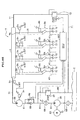
- Fig. 4 is an illustration for showing an entire configuration of the accumulator fuel injection device according to the second embodiment.
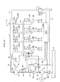
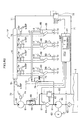
- a fuel injection device 1B according to the second embodiment is different from the fuel injection device 1A according to the first embodiment in the following points: (1) a pressure sensor (fuel supply passage pressure sensor)S Ps for detecting the pressure of the downstream side of the orifice 75 is provided instead of the differential pressure sensor S dP which is provided in the high pressure fuel supply passage 21 for supplying fuel to the injector 5A attached to each cylinder of the engine and detects the pressure difference between the upstream side and the downstream side of the orifice 75; (2) an ECU (control unit) 80B is provided instead of the ECU 80A; and (3) the definition of the orifice differential pressure ⁇ P OR which is used for calculating the orifice passing flow rate Q OR of fuel in the ECU 80B is changed.
- a pressure sensor fuel supply passage pressure sensor
- pressure signals detected by the four pressure sensors S Ps are input to the ECU 80B.
- the function of the ECU 80B according to the second embodiment is basically the same as that of the ECU 80A according to the first embodiment, however, signals used by the ECU 80B to calculate the orifice passing flow rate Q OR are different from those used in the first embodiment.
- the orifice passing flow rate Q OR is calculated by using the equation (1).
- the orifice differential pressure ⁇ P OR in the equation (1) is replaced by the pressure difference (Pc-Ps) between the common rail pressure Pc which is detected by the pressure sensor S Pc and the pressure Ps on the downstream side of the orifice 75, which is detected by the pressure sensor S Ps .
- the pressure on the upstream side of the orifice 75 in the high pressure fuel supply passage 21 is substantially equal to the common rail pressure Pc.
- an orifice passing flow rate Q OR of fuel i. e. an actual injection amount
- the ECU 80B can control an actual injection amount to be equal to a target fuel injection amount by adjusting the injection time T i of the injection command signal, similarly to the first embodiment.
- Fig. 5 is an illustration for showing an entire configuration of the accumulator fuel injection device of the third embodiment.
- a fuel injection device 1C of the third embodiment is different from the fuel injection device 1B of the second embodiment in the following points: (1) the pressure sensor S Pc for detecting the common rail pressure Pc is omitted; (2)an ECU (control unit) 80C is provided instead of the ECU 8OB; (3) a pressure sensor S Ps is provided instead of the pressure sensor S Pc for controlling the common rail pressure Pc; and (4) a method performed by the ECU 80C for calculating the orifice passing flow rate Q OR of fuel is changed from the method performed by the ECU 80B.
- pressure signals detected by the four pressure sensors S Ps are input to the ECU 80C.
- the ECU 80C performs a filtering process on the pressure signals input from the pressure sensors S Ps for cutting off a noise with a high frequency.
- the pressure Ps on the downstream side of the orifice 75 on which the filtering process has been performed is refereed to as a pressure Ps fil .
- the pressure vibration of the pressure Ps fil from the pressure sensor S Ps is comparatively smaller at an "aspiration stroke" which follows an "explosion stroke” and “exhaust stroke” after a fuel injection is performed and completed in one cylinder based on signals from a crank angle sensor (not shown) and a cylinder discriminating sensor (not shown) and the injection command signal for the cylinder generated by the ECU 80C.
- the pressure Ps fil from the pressure sensor S Ps in the state where its pressure vibration is comparatively smaller is substantially equal to the common rail pressure Pc.
- the ECU 80C samples the pressure Ps fil in the above described state where its pressure vibration is comparatively smaller and controls the pressure control valve 72 so as to control the common rail pressure Pc within a predetermined range.
- Only one pressure sensor S Ps among the four pressure sensors S Ps may be representatively used for controlling the common rail pressure Pc in the case of the 4 cylinder engine used in the third embodiment, or all of the four pressure sensors S Ps may be used to generate four signals of which sampling timing is different, and the common rail pressure Pc may be set to be the average value of the four signals.
- the function of the ECU 80C of the third embodiment is basically the same as that of the ECU 80B of the second embodiment except for the method for controlling the common rail pressure Pc. However, they are also different in that the orifice differential pressure used by the ECU 80C for calculating the orifice passing flow rate Q OR of fuel is not based on the pressure difference detected by the differential pressure sensor S dP or the pressure sensors S Pc , S Ps of the first or second embodiment, but based on a signal from the pressure sensor S Ps provided on the downstream side of the orifice 75.
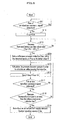
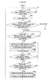
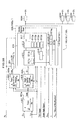
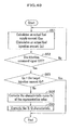
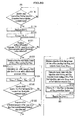
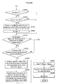
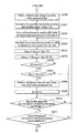
- Fig. 6 is a flowchart showing processing performed by the ECU 80C of the third embodiment for calculating an actual injection amount for one cylinder.
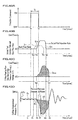
- Figs. 7A and 7B are graphs showing an output pattern of the injection command signal for one cylinder and the temporal variations of fuel flow in the high pressure fuel supply passage
- Fig. 7A is an illustration for showing an output pattern of an injection command signal.
- Fig. 7B is an illustration for showing the temporal variation of the pressure Ps fil on the downstream side of the orifice 75.
- Steps 03 to 07 Processing of Steps 03 to 07 is performed at a period of dozens of ⁇ sec, and ⁇ t, which is described later, is a period at which the filtering-processed pressure Ps fil is sampled, which is dozens of ⁇ seconds.
- Step 01 the ECU 80C determines whether or not the rise of the injection command signal for instructing injection is detected. If the ECU 80C determines that the rise of the injection command signal is detected (Yes), the processing proceeds to Step 02. If the ECU 80C determines that it is not detected (No), the processing repeats Step 01.
- t S the rising start timing of the injection command signal
- the rise of the injection command signal for instructing injection can be readily detected by time-differentiating the injection command signal.
- Step 02 the initial value of Q sum is reset to be 0.0.
- Q sum corresponds to an orifice passing flow amount calculated by time-integrating the orifice passing flow rate Q OR corresponding to one injection command signal.
- Step 03 the ECU 80C determines whether or not the pressure Ps fil on the downstream side of the orifice 75 which has been detected by the pressure sensor S Ps and filtering-processed decreases below a predetermined value P0 [(Ps fil ⁇ P 0 )?] . If the ECU 80C determines that the pressure Ps fil on the downstream side of the orifice 75 decreases below the predetermined value P0 (Yes), the processing proceeds to Step 04. If the ECU 80C determines that it does not (No), the processing repeats Step 03.
- the predetermined value P0 is set as follows: the pressure detected by the pressure sensor S Ps is filtering processed to remove a noise with a high frequency, such as a pressure pulsation caused by the filling operation of the high pressure pump 3B, a pressure pulsation caused by the propagation of the pressure vibration resulted from the injection operation of the injector 5B of other cylinders, and a pressure pulsation caused by a reflection wave of the injection operation of the injector 5A of the own cylinder, and the lowest value in the variation of the pressure that has been filtering-processed is set to be the predetermined value P0.
- the predetermined value P0 can be obtained in advance by experiments.
- Step 04 a pressure decrease amount ⁇ Pdown of the pressure Ps fil from the predetermined value P0 is calculated in order to calculate an orifice passing flow rate Q OR .
- the definition of ⁇ Pdown is shown in Fig. 7B .
- the orifice passing flow rate Q OR can be readily calculated by using the equation (1) in which the pressure decrease amount ⁇ Pdown is substituted for AP OR .
- Step 06 the ECU 80C determines whether or not the fall of the injection command signal is detected. If the ECU 80C determines that the fall of the injection command signal is detected (Yes), the processing proceeds to Step 07. If the ECU 80C determines that the fall of the injection command signal is not detected (No), the processing returns to Step 04, and repeats Steps 04 and 05.
- Fig. 7A the fall start timing of the injection command signal is represented as “t E " , and the fall completion timing of the injection command signal is represented as “t E ' “ .
- the fall of the injection command signal can be easily detected, for example, by time-differentiating the injection command signal.
- Step 07 the ECU 80C determines whether or not the filtering-processed pressure Ps fil on the downstream side of the orifice 75 increases to be equal to or more than the predetermined value P0 [(Ps fil ⁇ P 0 )?]. If the ECU 80C determines that the filtering-processed pressure Ps fil on the downstream side of the orifice 75 increases to be equal to or more than the predetermined value P0 (Yes), the processing proceeds to Step 08. If the ECU 80C determines that the filtering-processed pressure Ps fil on the downstream side of the orifice 75 does not (No), the processing returns to Step 04 and repeats Steps 04 and 05.
- Step 08 Q sum is set to be an actual fuel supply amount (actual injection amount).
- the dotted area encompassed by the line representing the predetermined value P0 and the curve representing the pressure Ps fil corresponds to the actual fuel supply amount (actual injection amount).
- the ECU 80B determines whether or not the fall of the fuel injection command signal is detected in Step 06, and after the fall of the fuel injection command signal is detected, the timing t E2 is detected at which the pressure Ps fil on the downstream side of the orifice 75 increases to be equal to or more than the predetermined value P0.
- the timing t E and the completion of the fuel flow through the orifice 75 may be detected even if Step 06 is omitted.
- the timing t S2 in Fig. 7B is also referred to as a "first timing”
- the timing t E2 at which the pressure Ps fil on the downstream side of the orifice 75 increases to be equal to or more than the predetermined value is also referred to as a "second timing” .
- pressure difference of the upstream and downstream sides of the orifice can be accurately calculated by, for example, using an average value of signals from the fuel supply passage pressure sensor S Ps in a period before the first timing (i. e. a period before the injection command signal is output) as an initial value of the upstream side of the orifice and detecting the decrease of the pressure Ps fil after the first timing.
- a fuel injection device of a modification of the third embodiment is described with reference to Figs. 5 , 8 and 9A to 9C .
- a configuration of the modification is the same as that of the third embodiment except for a method for detecting the "second timing" .
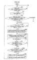
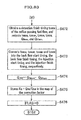
- Fig. 8 is a flowchart showing a process performed by the ECU 80C of the modification of the third embodiment for calculating an orifice passing flow rate Q OR for one cylinder.
- Figs. 9A to 9C are graphs showing an output pattern of the injection command signal for one cylinder and the temporal variations of fuel flow in the high pressure fuel supply passage.
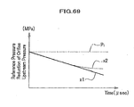
- Fig. 9A is a graph showing a reference pressure reduction line indicating the reduction of the pressure on the upstream side of the orifice 75 during fuel injection.
- Fig. 9B is a graph for showing an output pattern of the injection command signal.
- Fig. 9C is a graph showing the temporal variation of the pressure Ps fil on the downstream side of the orifice 75.
- the reference pressure reduction line indicating the pressure on the upstream side of the orifice 75 is set as shown in Fig. 9A based on the following experimental data which has been obtained in advance: the pressure on the upstream side of the orifice 75 at the time when the pressure difference ⁇ P OR of the orifice 75 becomes 0, which is caused by fuel flow after completion of the fuel injection from the injector 5A, always becomes lower than the initial pressure before the fuel injection is started as shown in Fig. 3D ; and the longer the injection time T i of fuel is, the greater the amount of the pressure reduction becomes.
- Fig. 9A exemplary shows, as the reference pressure reduction line, a reference pressure reduction line x1 and a reference pressure reduction quadratic curve x2.
- Pi represents the initial pressure before the fuel injection starts, and is floating as described later.
- Steps 13 to 18 is executed in a period of, for example, dozens of ⁇ seconds.
- ⁇ t which is described later, is a period for sampling the filtering-processed pressure Ps fil , which is dozens of ⁇ seconds.
- Step 11 the ECU 80C determines whether or not the rise of the fuel injection command signal is detected. If the ECU 80C determines that the rise of the fuel injection command signal is detected (Yes), the processing proceeds to Step 12. If the ECU 80C determines that the rise of the fuel injection command signal is not detected (No), the processing repeats Step 11.
- the timing "t s " represents the rise of the injection command signal.
- Step 12 Q sum is reset to be 0. 0.
- Q sum corresponds to an orifice passing flow amount which is calculated by time integrating an orifice passing flow rate Q OR corresponding to one fuel injection command signal.
- the ECU 80C determines whether or not the pressure Ps fil on the downstream side of the orifice 75, which is detected by the pressure sensor S Ps and is filtering-processed, decreases below a predetermined value [(Ps fil ⁇ P 0 - ⁇ P ⁇ )?]. If the ECU 80C determines that the pressure Ps fil on the downstream side of the orifice 75 decreases below the predetermined value (P 0 - ⁇ P ⁇ ) (Yes), the processing proceeds to Step 14. If the ECU 80C determines that the pressure Ps fil on the downstream side of the orifice 75 does not(No), the processing repeats Step 13.
- the timing "t S2 " represents a time when the pressure Ps fil on the downstream side decreases below the predetermined value (P 0 - ⁇ P ⁇ ).
- the predetermined value P0 is set as follows: the pressure signal detected by the pressure sensor S Ps is filtering processed to remove a noise with a high frequency, such as a pressure pulsation caused by the filling operation of the high pressure pump 3B, a pressure pulsation caused by the propagation of the pressure vibration resulted from the injection operation of the injector 5A of other cylinders, and a pressure pulsation caused by a reflection wave of the injection operation of the injector 5A of the own cylinder, and the average value of the variation of the pressure Ps fil that have been filtering-processed is set to be the predetermined value P0.
- ⁇ P ⁇ is a predetermined difference exceeding the difference between the predetermined pressure P0 and the lowest value of the filtering-processed pressure Ps fil which may be reached by its vibration.
- Step 14 a reference pressure reduction line is set, taking the pressure Ps fil in Step 13 (at the timing t S2 ) as an initial value Pi as shown in Fig.9C .
- the initial value Pi may be equal to the predetermined value (P 0 - ⁇ P ⁇ ).
- the initial value Pi may not be equal to the predetermined value (P 0 - ⁇ P ⁇ ), since the pressure Ps fil may be used in Step 14 which is sampled in the period next to the period in which the pressure Ps fil used in Step 13 is sampled.
- Step 15 the amount of pressure decrease ⁇ Pdown of the pressure Ps fil from the reference pressure reduction line whose initial value is the initial value Pi, is calculated in order to calculate the orifice passing flow rate Q OR .
- the definition of ⁇ Pdown is shown in Fig.9C .
- the orifice passing flow rate Q OR can be readily calculated by using the equation (1) in which the pressure decrease amount ⁇ Pdown is substituted for ⁇ P OR .
- Step 17 the ECU 80C determines whether or not the fall of the fuel injection command signal is detected. If the ECU 80C determines that the fall of the fuel injection command signal is detected (Yes), the processing proceeds to Step 18. If the ECU 80C determines that the fall of the fuel injection command signal is not detected (No), the processing repeats Steps 15 and 16.
- t E represents the fall start timing of the injection command signal
- t E ' represents the fall completion timing of the injection command signal
- Step 18 the ECU 80C determines whether or not the filtering processed pressure Ps fil on the downstream side of the orifice 75 increases to be equal to or more than the reference pressure reduction line reference pressure reduction. If the ECU 80C determines that the filtering processed pressure Ps fil on the downstream side of the orifice 75 increases to be equal to or more than the reference pressure reduction line (Yes), the processing proceeds to Step 19. If the ECU 80C determines that it does not (No), the processing returns to Step 15, and repeats Steps 15 and 16.
- t E2 represents a time when the pressure Ps fil on the downstream side of the orifice 75 increases to be equal to or more than the reference pressure reduction line.
- Step 19 Qsum is set as an actual fuel supply amount (actual injection amount).
- the dotted area which is encompassed by the reference pressure reduction line x1 and the curve indicating the pressure Ps fil corresponds to the actual fuel supply amount (actual injection amount).
- the timing t S2 in Fig. 9C in the third embodiment is also referred to as a "first timing”
- the timing t E2 when the pressure Ps fil on the downstream side of the orifice 75 increases to be equal to or more than the reference pressure reduction line is also referred to as a "second timing” .
- the injector 5A which is a direct acting fuel injection valve as shown in Fig. 2
- the actuator 6A is a type of an actuator which directly moves the piston 16 by using the electromagnetic coil 34, however, an injector to be used is not limited to those described above.
- an injector of the following configuration may be used: a stack formed by stacking piezoelectric elements in layers is provided on the lower side of the piston flange part 16a instead of the electromagnetic coil 34, and when voltage is applied to the stack of the piezoelectric elements, the stack lifts the piston 16 upward against the energizing force of the coil spring 37 for injecting fuel, and when the voltage is stopped being applied to the stack of the piezoelectric element, the piston 16 is pushed downward by the coil spring 37 so that the fuel injection is stopped.
- a fuel injection device of a fourth embodiment of the present invention is described in detail below with reference to Figs. 10 and 11 .
- Fig. 10 is an illustration showing an entire configuration of an accumulator fuel injection device of the fourth embodiment.
- Fig. 11 is a conceptional configuration drawing of a back pressure fuel injection valve (injector) which is used in the accumulator fuel injection device according to the fourth embodiment.
- a fuel injection device 1D of the fourth embodiment differs from the fuel injection device 1A of the first embodiment in that: (1)an injector 5B including an actuator 6B, which is a back pressure fuel injection valve, is used ; (2) in accordance with (1), a drain passage 9 is connected to the injector 5B provided in each cylinder, and the drain passages 9 are further connected to a return fuel pipe 73, which is connected to the low pressure fuel supply passage 61 on the discharge side of the low pressure pump 3A via a flow controller in which a check valve 74 and the orifice 76 is connected in parallel; (3) the fuel injection device 1D in the fourth embodiment is controlled by the ECU(control unit)80D.
- the injector 5B is a well known injector, and is provided to each cylinder of the engine.
- the configuration of the injector 5B is briefly described below.
- the injector 5B includes the injector body 13 of which distal end has one or more fuel injection ports 10, the nozzle needle 14 which is slidably supported in the injector body 13, and the piston 16 which is connected to the upper side of the nozzle needle 14 via a pressure pin 15 to be integrally reciprocated and displaced with the nozzle needle 14.
- the injector body 13 includes the nozzle body 17, and the nozzle holder 19.
- the oil reservoir 20 is formed inside of the nozzle body 17 so as to fill high pressure fuel around the nozzle needle 14.
- the oil reservoir 20 is always communicated with the common rail 4 via the fuel passage 25 and the high pressure fuel supply passage 21.
- the nozzle body 17 is fastened to the nozzle holder 19 with a retaining nut 22.
- the nozzle holder 19 constitutes a cylinder which forms a long hole 23 in the longitudinal direction at its center part.
- the long hole 23 slidably supports the piston 16.
- a back pressure chamber 7 which has an opening on the upper side of the nozzle holder 19.
- a fuel passage 25 which branches from a fuel passage communicated with the high pressure fuel supply passage 21 and the high pressure fuel supply passage 21 formed in the nozzle holder 19 is communicated with the back pressure chamber 7 via a communication passage 26 formed in the first throttle forming member 11.
- the nozzle needle 14 is disposed at the same axial center as the center axis of the actuator 6B which uses a two-way solenoid valve, and is slidably supported in the inner circumference of the nozzle body 17.
- the nozzle needle 14 is lifted to form a fuel passage between the distal end of the nozzle needle 14 and the nozzle body 17.
- the fuel passage communicates the oil reservoir 20 with the fuel injection port 10 so that fuel is injected to the engine.
- the distal end of the nozzle needle 14 is seated on a seat surface 17a of the nozzle body 17 so that the injection of the high pressure fuel is finished.
- a coil spring 27 for energizing the nozzle needle 14 in the valve closing direction is provided between the major diameter part of the pressure pin 15 and the nozzle holder 19.
- the piston 16 is disposed at the same axial center as the center axis of the actuator 6B, and is supported such that the piston 16 is slidable along the inner circumferential surface of the long hole 23 of the nozzle holder 19.
- the actuator 6B includes: an iron core 33 which is disposed above the valve body 32; the electromagnetic coil 34 which is wound around a housing part of the iron core 33; a valve 35 which is slidably moved in the valve body 32; the stopper 36 for regulating the maximum lift amount of the valve 35; and the coil spring 37 for biasing the valve 35 in the valve closing direction as shown in Fig. 11 .
- valve body 32, the iron core 33, the electromagnetic coil 34, the valve 35 and the stopper 36 are fastened to the upper end of the nozzle holder 19 of the injector 5B with a retaining nut (not shown) in a state where the lower end of the valve body 32 is liquid tightly in contact with the nozzle holder 19.
- the first and second throttle forming members 11, 12 are liquid-tightly fit into a recessed part 39 which is opened for communicating with the back pressure chamber 7.
- a fuel chamber 40 whose internal diameter is larger than the recessed part 39 is provided inside of the valve body 32.
- the fuel chamber 40 is connected to the return fuel pipe 73 communicated with the fuel tank 2 via the drain passage 9 which is provided in the valve body 32, or the like.
- the iron core 33 is magnetized to be an electric magnet and generates magnet motive force when the electromagnetic coil 34 is energized by the control of the ECU80D.
- the valve 35 includes a plate-like sealing part 42 at its lower end and a stick-like part 43 at its upper end. When the iron core 33 generates the magnet motive force, the valve 35 is attracted and moved upward, and the stick-like part 43 of the valve 35 is seated on the lower end of the stopper 36. After the energization of the electromagnetic coil 34 is finished, the iron core 33 loses the magnet motive force, and the sealing part 42 of the valve 35 is seated on the upper end of the second throttle forming member 12 due to the downward energizing force of the coil spring 37.
- the first and second throttle forming members 11, 12 are made, for example, of alloy steel or carbon steel, such as SCM 420.
- the first and second throttle forming members 11, 12 are formed to be disc shape whose center axis corresponds to the center axis of the valve 35 of the actuator 6B.
- the first throttle forming member 11 and the second throttle forming member 12 respectively includes orifices 51 and 52 of which internal diameter is smaller than that of the fuel passage 25 and the communication passage 26.
- the orifice 51 is arranged a little closer to the communication passage 26 with respect to the center axis of the first throttle forming member 11, and the orifice 52 is arranged at the same axial center as the center axis of the second throttle forming member 12.
- the orifice 51 throttles the passage section area of a first passage which communicates the back pressure chamber 7 with the orifice 52.
- the orifice 52 throttles the passage section area of a second passage which communicates the orifice 51 and the drain passage 9.
- the orifice 52 is a valve seat member and has an internal diameter 1.4 to 1.6 times larger than that of the orifice 51.
- the lower side (not shown) of the orifices 51 and 52 is formed such that the inner diameters of the back pressure chamber 7 is larger than the diameter of the orifices 51 and 52 on their lower sides.
- the outlet of the orifice 51 is arranged to be opposed to a tapered passage wall surface of the inlet of the orifice 52.
- Figs. 12A to 12D are graphs showing an output pattern of the injection command signal for one cylinder and the temporal variations of fuel flow in the high pressure fuel supply passage.
- Fig. 12A is a graph for showing an output pattern of the injection command signal.
- Fig. 12B is a graph for explaining the temporal variation of an actual fuel injection rate and a back flow rate.
- Fig. 12C is a graph for showing the temporal variation of an orifice passing flow rate of fuel.
- Fig. 12D is a graph for showing the temporal variation of the pressures on the upstream and downstream sides of the orifice 75.
- the injection command signal of fuel is conceptually represented as a wide pulse.
- the timing when the injection command signal starts to rise is represented as “t s ".
- the timing when the injection command signal starts to fall is represented as “t E ", and the timing when the injection command signal has completed falling is represented as "t E '”.
- a back flow of fuel is started by the lift up of the valve 35 (see Fig. 10 ) of the injector 5B, which is a back pressure fuel injection valve.
- the back flow of the fuel returns to the low pressure fuel supply passage 61 via the fuel passage 25, the communication passage 26, the back pressure chamber 7, the orifices 51, 52, the fuel chamber 40 and the drain passage 9.
- the back flow starts at the timing t SA .
- the start of the back flow is a little delayed from the rising start timing t S of the injection command signal.
- the back flow makes the pressure of the back pressure chamber 7 to be lower than that of the oil reservoir 20, whereby the piston 16 is moved upward.
- an actual fuel injection is started at the timing "t SB " as shown by the curve a in Fig. 12B .
- the electromagnetic coil 34 (see Fig. 11 ) is stopped being energized, and the coil spring 37 pushes the valve 35 downward, whereby the flow passage for the back flow is closed, and the back flow is finished at the timing t EA as shown by the curve b in Fig. 12B .
- the pressure of the back pressure chamber 7 (see Fig. 11 ) and that of the oil reservoir 20 are balanced, and the nozzle needle 14 is moved downward together with the piston 16 by the energizing force of the coil spring 27.
- the nozzle needle 14 is seated on the seat surface 17a, whereby the fuel injection is finished at the timing t EB as shown by the curve a in Fig. 12B .
- the orifice passing flow rate Q OR can be calculated.
- the dotted area of the orifice passing flow rate Q OR shown in Fig. 12C is equal to the area which is calculated by adding the areas of the back flow amount Q BF and the actual injection amount Q A (actual fuel supply amount) shown in Fig. 12B .
- the orifice passing flow rate Q OR can be readily calculated based on the orifice differential pressure ⁇ P OR by using the equation (1), similarly to the first embodiment.
- the ECU80D stores in a memory in advance an actual injection amount conversion factor y in the form of, for example, a correlation equation of signal parameters.
- the actual injection amount conversion factor ⁇ is a factor which indicates the ratio between the calculated orifice passing flow amount Q sum and the actual injection amount depending on the output pattern of the fuel injection command signal.
- the actual injection amount conversion factor ⁇ which depends on the output pattern of the injection command signal, is defined as the equation (2) by taking, for example, a signal waveform area Ap as the signal parameter.
- the actual injection amount conversion factor ⁇ is defined as the equation (2) in such a manner that the signal waveform area Ap corresponds to one signal waveform area of an independent injection command signal having the injection time T i if the injection command signal is the independent injection command signal which is temporally apart from another injection command signal by a predetermined period, and if the injection command signal is comprised of a plurality of injection command signals which are temporally close to one another in a predetermined period, the signal waveform area Ap corresponds to the summation of the signal waveform areas of the plurality of the injection command signals.
- ⁇ F ⁇ A P ⁇ M P where M P is a parameter indicating an independent signal waveform or a plural proximity signal waveforms.
- the ECU80D determines whether or not the injection command signal is an independent signal waveform or a plural proximity signal waveforms based on its output pattern, and calculates the signal waveform area Ap so as to set the actual injection amount conversion factor ⁇ by the equation (2).
- the calculated orifice passing flow amount Q sum is multiplied by the actual injection amount conversion factor ⁇ to calculate the actual injection amount.
- the orifice passing flow rate Q OR is easily calculated based on the orifice differential pressure ⁇ P OR detected by the differential pressure sensor S dP by using the equation (1).
- the orifice passing flow rate Q OR based on the orifice differential pressure ⁇ P OR , it is possible to accurately calculate an actual fuel supply amount to the injector 5B. Further, the actual injection amount can be calculated by multiplying the actual fuel supply amount by the actual injection amount conversion factory.
- the ECU 80D sets the actual injection amount conversion factory in accordance with an output pattern of the fuel injection signal, it is possible to accurately calculate the actual fuel injection amount from the actual fuel supply amount.
- the fuel injection of the injector 5B is generally multi-injection including "Pilot injection” , "Pre injection” , “After injection” and “Post injection” in order to reduce PM (particulate material), NOx and a combustion noise and to increase exhaust temperature or to activate catalyst by supplying a reducing agent.
- the ECU 80D can control the actual fuel supply amount to be equal to the target amount by adjusting the injection time T i of the injection command signal since the actual injection amount can be accurately calculated based on the orifice differential pressure ⁇ P OR .
- the actual injection amount conversion factor y which is used for calculating the actual fuel injection amount from the orifice passing flow amount (actual fuel supply amount) Q sum is variable, however, it may be an approximate fixed value.
- Fig. 13 is an illustration for showing an entire configuration of the accumulator fuel injection device of the fifth embodiment.
- the fuel injection device 1E differs from the fuel injection device 1D of the fourth embodiment in that: (1) a pressure sensor S Ps for detecting the pressure on the downstream side of the orifice 75 is provided instead of a differential pressure sensor S dP for detecting the pressure difference between the upstream side and the downstream side of the orifice 75 which is provided in the high pressure fuel supply passage 21 for supplying fuel to the injector 5B attached to each cylinder of the engine; (2)an ECU(control unit)80E is provided instead of the ECU80D; (3) the definition of the orifice differential pressure ⁇ P OR which is used for calculating the orifice passing flow rate Q OR of fuel in the ECU 80E is changed.
- the fifth embodiment uses the injector 5B, which is a back pressure fuel injection valve, instead of the injector 5A, which is a direct acting fuel injection valve, and is modified from the second embodiment to be adapted to the injector 5B.
- pressure signals detected by the four pressure sensors S Ps are input to the ECU 80E.
- the function of the ECU 80E according to the fifth embodiment is basically the same as that of the ECU 80D according to the fourth embodiment, however, signals used by the ECU 80E to calculate the orifice passing flow rate Q OR are different from those used in the fourth embodiment.
- the orifice passing flow rate Q OR is calculated by using the equation (1).
- the orifice differential pressure ⁇ P OR in the equation (1) is replaced by the pressure difference (Pc-Ps) between the common rail pressure Pc which is detected by the pressure sensor S Pc and the pressure Ps on the downstream side of the orifice 75, which is detected by the pressure sensor S Ps .
- the ECU 80E can control the actual injection amount to be equal to a target fuel injection amount by adjusting the injection time T i of the injection command signal, similarly to the first embodiment.
- Fig. 14 is an illustration for showing an entire configuration of the accumulator fuel injection device of the sixth embodiment.
- a fuel injection device 1F of the sixth embodiment is different from the fuel injection device 1E of the fifth embodiment in the following points: (1) the pressure sensor S Pc for detecting the common rail pressure Pc is omitted; (2) an ECU (control unit) 80F is provided instead of the ECU 80E; (3) a pressure sensor S Ps is provided instead of the pressure sensor S Pc for controlling the common rail pressure Pc; and (4) a method performed by the ECU 80F for calculating the orifice passing flow rate Q OR of fuel is changed from the method performed by the ECU 80E.
- the sixth embodiment uses the injector 5B, which is a back pressure fuel injection valve, instead of the injector 5A, which is a direct acting fuel injection valve, and is modified from the third embodiment to be adapted to the injector 5B.
- pressure signals detected by the four pressure sensors S Ps are input to the ECU 80C.
- the ECU 80F performs a filtering process on the pressure signals input from the pressure sensors S Ps for cutting off a noise with a high frequency.
- the pressure vibration of the pressure Ps fil from the pressure sensor S Ps becomes comparatively smaller at an "aspiration stroke” and “compression stroke” which follows the "explosion stroke” and “exhaust stroke” after a fuel injection is performed and completed in one cylinder based on signals from a crank angle sensor (not shown) and a cylinder discriminating sensor (not shown) and the injection command signal for each cylinder generated by the ECU 80F.
- the pressure Ps fil from the fuel supply passage pressure sensor S Ps in the state where its pressure vibration is comparatively smaller is substantially equal to the common rail pressure Pc.
- the ECU 80F samples the pressure Ps fil in the above described state where its pressure vibration is comparatively small and controls the pressure control valve 72 to control the common rail pressure Pc within a predetermined range.
- Only one pressure sensor S Ps among the four pressure sensors S Ps may be representatively used for controlling the common rail pressure Pc in the case of the 4 cylinder engine used in the third embodiment, or all of the four pressure sensors S Ps may be used to generate four signals of which sampling timing is different, and the common rail pressure Pc may be set to be the average value of the four signals.
- the function of the ECU 80F of the sixth embodiment is basically the same as that of the ECU 80E of the fifth embodiment except for the method for controlling the common rail pressure Pc. However, they are also different in that the orifice differential pressure used by the ECU 80C for calculating the orifice passing flow rate Q OR of fuel is not based on the pressure difference detected by the differential pressure sensor S dP or the pressure sensors S Pc , S Ps as in the fourth or fifth embodiment, but is based on only the signal from the pressure sensor S Ps provided on the downstream side of the orifice 75.
- Fig. 15 is a flow chart showing a control flow performed by the ECU 80F of the sixth embodiment for calculating the orifice passing flow rate Q OR and the actual injection amount for one cylinder.
- Figs. 16A and 16B are graphs showing an output pattern of the injection command signal for one cylinder and the temporal variations of fuel flow in the high pressure fuel supply passage.
- Fig. 16A is a graph for showing an output pattern of the injection command signal.
- Fig. 16B is a graph showing the temporal variation of the pressure Ps fil on the downstream side of the orifice.
- Steps 03 to 07 in the flowchart shown in Fig. 15 is the same as that of Steps 03 to 07 in the flowchart of the third embodiment shown in Fig. 6 .
- the flowchart of the sixth embodiment is different from that of the third embodiment only in that Step 08A is substituted for Step 08, and Step 09 is added.
- Step 08A is substituted for Step 08
- Step 09 is added.
- corresponding steps are assigned similar reference numerals, and descriptions thereof will be omitted.
- Fig. 7A” , “Fig. 7B " and “injector 5A” in the explanation of the flowchart shown in Fig. 6 should be read as “ Fig. 16A” , “Fig. 16B “ and “injector 5B” , respectively.
- Step 08A after Step 07 the actual injection amount conversion factor ⁇ is obtained by referring to the injection command. Then, Qsum is multiplied by the actual injection amount conversion factor ⁇ to calculate an actual injection amount (Step 09).
- the dotted area encompassed by the line indicating the predetermined value P0 and the curve indicating the pressure Ps fil corresponds to Qsum (i.e. actual fuel supply amount).
- the timing t S2 in Fig. 16B is also referred to as the "first timing”
- the timing t E2 at which the pressure Ps fil on the downstream side of the orifice 75 increases to be equal to or more than the predetermined value is also referred to as the "second timing” .
- the orifice passing flow rate Q OR based on the equation (1) in which the pressure decrease amount ⁇ Pdown(P 0 -Ps fil ) is substituted for the orifice differential pressure ⁇ P OR by using only the pressure signal from the pressure sensor S Ps for detecting the pressure on the downstream side of the orifice 75.
- the actual injection amount can be calculated for each cylinder and each injection command signal by multiplying the orifice passing flow amount Qsum by the actual injection amount conversion factory which depends on the command signal.
- the ECU 80F is allowed to control the actual injection amount to be equal to a target fuel injection amount by adjusting the injection time T i of the injection command signal, similarly to the fifth embodiment.
- a fuel injection device of a modification of the sixth embodiment is described with reference to Figs. 9A , 12A to 12D , 17 and 18A to 18B .
- a configuration of the modification is the same as that of the sixth embodiment except for the method for detecting the "second timing" .
- the modification of the sixth embodiment uses the injector 5B, which is a back pressure fuel injection valve, instead of the injector 5A, which is a direct acting fuel injection valve, and is modified from the modification of the third embodiment to be adapted to the injector 5B.
- Fig. 17 is a flowchart showing a process performed by the ECU 80F of the modification of the sixth embodiment for calculating an orifice passing flow rate Q OR for one cylinder.
- Figs. 18A and 18B are graphs showing an output pattern of the injection command signal for one cylinder and the temporal variations of fuel flow in the high pressure fuel supply passage.
- Fig. 18A is a graph for showing an output pattern of the injection command signal.
- Fig. 18B is a graph for showing the temporal variation of the pressure Ps fil on the downstream side of the orifice 75.
- a reference pressure reduction line indicating the pressure on the upstream side of the orifice 75 is set in advance as shown in Fig. 9A based on the following experimental data: the pressure on the upstream side of the orifice 75 at the time when the pressure difference ⁇ P OR of the orifice 75 becomes 0, which is caused by fuel flow after completion of the fuel injection from the injector 5B, always becomes lower than the initial pressure before the fuel injection is started as shown in Fig. 12D ; and the longer the injection time T i of fuel is, the greater the amount of the pressure reduction becomes.
- Steps 11 to 18 in the flowchart shown in Fig. 17 is the same as that of Steps 11 to 18 in the flowchart of the modification of the third embodiment shown in Fig. 8 .
- the flowchart of the modification of the sixth embodiment is different from that of the modification of the third embodiment only in that Step 19A is substituted for Step 19 and Step 20 is added.
- Step 19A is substituted for Step 19 and Step 20 is added.
- corresponding steps are assigned similar reference numerals, and descriptions thereof will be omitted.
- Fig. 9B” , " Fig. 9C " and "injector 5A" in the explanation of the flowchart shown in Fig. 8 should be read as “ Fig. 18A” , “ Fig. 18B “ and “injector 5B” , respectively.
- the timing t S2 of the modification of the sixth embodiment shown in Fig. 18B is also referred to as the "first timing”
- the timing t E2 at which the pressure Ps fil on the downstream side of the orifice 75 increases to be equal to or more than the predetermined value is also referred to as the "second timing” .
- the actual injection amount can be more accurately calculated than the third embodiment by using only the pressure Ps fil on the downstream side of the orifice 75.
- the injector 5B which is a back pressure fuel injection valve as shown in Fig. 11
- the actuator 6B is a type of an actuator which moves the valve 35 by using the electromagnetic coil 34 to control the pressure of the back pressure chamber 7
- an injector to be used is not limited to those described above.
- an injector of the following configuration may be used: a control valve of a three-way valve structure is moved by using a piezoelectric stack to control the pressure of a back pressure chamber provided above a nozzle needle for injecting fuel or stopping the fuel injection.
- the volume of a fuel passage including the high pressure fuel supply passage 21 in the fuel injection devices 1A to 1F that is lower than the orifice 75 and the fuel passage to a fuel injection port 10 inside the injector 5A or 5B (the fuel passage 25 and the oil reservoir 20 (see Figs. 2 and 11 )) is designed to exceed the maximum actual fuel supply amount which is supplied through the high pressure fuel supply passage 21 for an explosion stroke among the cycles of aspiration, compression, explosion and exhaust in one cylinder, such as the maximum actual fuel supply amount required when the maximum torque is required by a fully-opened accelerator. Therefore, the high pressure fuel which is accumulated in a part lower than the orifice 75 before fuel injection is enough for any required fuel injection in a cylinder
- the left end of the time axis represents the timing at which an injection signal for other cylinder, #2 cylinder, is generated, and the center of the time axis which is indicated as "0" represents the timing at which an injection signal for the own cylinder, # 1cylinder, is generated.
- the accuracy in controlling a fuel injection amount is improved because the variation of the common rail pressure Pc is reduced in the control of the ECU 80(which represents the ECU 80A to 80F) for stabilizing the common rail pressure Pc to be substantially constant by controlling the pressure control valve 72.
- the variation of the pressure of the high pressure fuel supply passage 21 in the vicinity of the injector for own cylinder (#1cylinder) at the time of fuel injection in the other cylinder (#2 cylinder) is reduced and is stabilized rapidly if the orifice 75 is provided. If the number of cylinders of the engine is more than 4, the time interval between fuel injections for the other cylinder and the own cylinder may be shorter. In this case, the rapid stabilization of the pressure variation caused by the fuel injection in the other cylinder means that disturbance in controlling an actual injection amount for the own cylinder can be suppressed.
- the initial pressure decrease is not different between the part E and the part F regardless of whether or not the orifice 75 is provided to the high pressure fuel supply passage 21.
- the pressure increase after the initial pressure decrease is smaller because fuel supply is restricted by a large resistance of the orifice 75 due to its narrowed flow passage when the amount of fuel corresponding to the amount of fuel injected from the injector is supplied from the common rail 4.
- the pressure increase after the initial pressure decrease is greater as shown in the part F because the fuel supply amount is larger due to the smaller resistance when the amount of fuel corresponding to that injected from the injector is supplied from the common rail 4.
- the pressure vibration also continues longer since the reflection wave of the pressure vibration is bigger and the effective volume of pressure propagation includes the volume of the common rail 4.
- a pressure change dP/dt caused when the volume of fluid is changed by ⁇ Q in a space of a predetermined volume V is represented as the equation (3).
- / dt dP K V ⁇ ⁇ ⁇ Q
- K is a constant value
- the volume V corresponds to the summation of the volume of the high pressure fuel supply passage 21 and the volume of the fuel passage to the fuel injection port 10 in the injector if the orifice 75 is provided, while if the orifice 75 is not provided, the volume V corresponds to the volume which is obtained by adding the volume of the common rail 4 to the summation of the above volumes.
- the pressure decrease of the high pressure fuel supply passage 21 in the vicinity of the common rail is greater than in the case where the orifice 75 is not provided as shown in the part G in Fig. 19C according to the equation (3), and the rebound of the pressure vibration (pressure increase) after the pressure decrease is also larger.
- the period for which the pressure vibration continues is shorter since the substantial volume of the pressure vibration does not include the common rail 4.
- the pressure variation in the vicinity of common rail 4 at the time of fuel injection is larger with the orifice 75. If the orifice 75 is provided, the pressure variation in the vicinity of the injector at the time of fuel injection can be made smaller, and the pressure variation can be stabilized in a shorter time, which allows to accurately control each injection amount when plural injections are performed consecutively by the injector.
- the orifice 75 becomes a resistance for fluid, and thus the impact pressure of the high pressure fuel supply passage 21 in the vicinity of the injector, which is caused by fuel supply at the time of the completion of the fuel injection becomes smaller.
- the reflection wave of the impact pressure is also smaller, and the effective volume of the pressure propagation is limited to the volume of the high pressure fuel supply passage 21 and does not include the volume of the common rail 4, whereby the pressure vibration is rapidly stabilized. This means that the pressure vibration propagated to the high pressure fuel supply passages 21 of other cylinders via the common rail 4 from the own cylinder (#1cylinder) is smaller.
- the injection command signal generated by the ECU 80A to 80F for controlling the fuel injection amount for each cylinder controls the fuel injection amount based on the period of the injection command signal, however, in addition to the period of the injection command signal, the fuel injection amount may be controlled by the lift amount of the nozzle needle 14 of the injectors 5A, 5B, which is controlled by changing the height of the injection command signal.
- the injectors 5A and 5B directly inject fuel into the combustion chamber of each cylinder, however, configurations of the present invention are not limited to this.
- the present invention also includes a configuration where the injectors 5A and 5B inject fuel in a subsidiary chamber (premixed space) which is formed adjacent to the combustion chamber of each cylinder, and a configuration where the injectors 5A and 5B inject fuel in the aspiration port of each cylinder. In these configurations, the advantages of the first to sixth embodiments including the modifications can be also obtained.
- a fuel injection device according to a seventh embodiment of the present invention is described in detail with reference to Fig. 20 .
- Fig. 20 is an entire configuration of the accumulator fuel injection device in the seventh embodiment.
- the seventh embodiment has a configuration which is based on that of the second embodiment, and is different therefrom only in that: (1) the pressure sensor S Ps is provided only in the high pressure fuel supply passage (fuel supply passage) 21A of a representative cylinder, which is the cylinder 41A, on the downstream side of the orifice 75, and the pressure sensor S Ps is not provided in the high pressure fuel supply passages (fuel supply passages) 21B, 21B, 21B for the other cylinders 41B, 41C, 41D; (2) an ECU (control unit) 80G is provided instead of the ECU 80B.
- Each cylinder 41 of the 4 cylinder engine is represented as 41A, 41B, 41C, 41D, and is assigned the cylinder numbers "#1" " #2", “ #3” and " #4", respectively in Fig. 20 ).
- the low pressure pump 3A and the high pressure pump 3B are also referred to as a "fuel pump”.
- the cylinder 41A is also referred to as a "first cylinder”
- the cylinders 41B, 41C, 41D are also referred to as a "second cylinder” .
- the injector 5A in the seventh embodiment is a direct acting injector as shown in Fig. 2 .
- the ECU 80G performs a filtering process on the signal indicating the fuel supply passage pressure Ps input from the pressure sensors S Ps for cutting off a noise with a high frequency
- the fuel supply passage pressure Ps which has been filtering-processed is called a fuel supply passage pressure Ps fil , or just "pressure Ps fil ".
- the pressure vibration of the pressure Ps fil from the pressure sensor S Ps becomes comparatively smaller at an "aspiration stroke” and “compression stroke” which follows the "explosion stroke” and “exhaust stroke” after a fuel injection is performed and completed in one cylinder based on signals from a crank angle sensor (not shown) and a cylinder discriminating sensor (not shown) and the injection command signal for each cylinder generated by the ECU 80G.
- the pressure Ps fil from the fuel supply passage pressure sensor S Ps in the state where its pressure vibration is comparatively smaller is substantially equal to the common rail pressure Pc.
- the common rail pressure Pc detected by the common rail pressure sensor S Pc is also filtering-processed similarly to the pressure signal detected by the fuel supply passage pressure sensor S Ps , however, the common rail pressure is just referred to as "Pc" .
- ECU80G engine controlling device which is used in the accumulator fuel injection device of the seventh embodiment is described with reference to Figs. 21 to 24B .
- Fig. 21 is a functional block diagram of the engine controlling device used in the accumulator fuel injection device of the seventh embodiment.
- Fig. 22 is a conceptual graph of a two dimensional map for determining the injection time T i for obtaining the target injection amount Q T .
- Fig. 23 is a conceptual graph of a map of a correction factor K 1 for obtaining the correction factor of the injection time, where a target injection amount, an injection time and a common rail pressure are taken as parameters.
- the ECU 80G includes a micro computer (including a CPU, ROM, RAM, non-volatile memory such as a flash memory)(not shown), an interface circuit (not shown), and an actuator driving circuit 806 (806A to 806D in Fig. 21 ) for driving the actuator 6A.
- the micro computer electronically controls the actuator 6A by calculating an optimum fuel injection amount and an optimum injection timing based on signals from various sensors such as, an engine rotation speed sensor, a cylinder discriminating sensor, a crank angle sensor, a water temperature sensor, an intake air temperature sensor, an intake air pressure sensor, an accelerator (throttle) opening sensor, a fuel temperature sensor S Tf , a common rail pressure sensor S Pc , and a fuel supply passage pressure sensor S Ps .
- a piezoelectric stack having a high response speed is used for the actuator 6A.
- a CPU of a high calculation speed such as a multi core CPU is used as the CPU of the micro computer.
- the ECU 80G may include a motor driving circuit for driving the motor 63, or the motor driving circuit may be provided outside of the ECU 80G.
- a required torque calculation unit 801 calculates a required torque Trqsol based on the accelerator opening ⁇ th and the engine rotation speed Ne.
- a target injection amount calculation unit 802 calculates a target injection amount Q T based on the engine rotation speed Ne and the calculated required torque Trqsol.
- An injection control unit 805G determines an injection start instruction timing for fuel injection, a corrected injection time which corresponds to the target injection amount Q T , and an injection finish instruction timing based on the engine rotation speed Ne, the calculated required torque Trqsol, the calculated target injection amount Q T , a TDC signal, a crank angle signal, a common rail pressure Pc detected from the common rail pressure sensor S Pc (see Fig. 20 ), and a fuel supply passage pressure Ps fil detected by the fuel supply passage pressure sensor S Ps provided in the high pressure fuel supply passage 21A.
- the ECU 80G sets the injection start instruction timing and the injection finish instruction timing, and outputs them to the actuator driving circuits 806A, 806B, 806C, and 806D as the injection command signal to drive the actuator 6A of each injector 5A.
- the injection control unit 805G also calculates an actual fuel supply amount to the injector 5A of each cylinder 41.
- the injection control unit 805G stores the ratio of the target injection amount Q T and the calculated actual injection amount as a correction factor since the calculated actual fuel supply amount corresponds to the actual injection amount of the injector 5A.
- the injection control unit 805G uses the correction factor to correct the injection time when determining the injection time.
- a common rail pressure calculation unit 803 calculates a target common rail pressure Pcsol based on the required torque Trqsol which is calculated in the required torque calculation unit 801 in the ECU80G and the engine rotation speed Ne with reference to a two dimensional map 803a of the common rail pressure.
- a common rail pressure control unit 804 compares the calculated target common rail pressure Pcsol with a signal from the common rail pressure Pc, and outputs a control signal to the flow regulating valve 69 and the pressure control valve 72 to control the common rail pressure Pc to be equal to the target common rail pressure Pcsol.
- the ECU 80G electronically stores in its ROM a two dimensional map 801a that stores the optimum required torque Trqsol which is experimentally determined with respect to the accelerator opening ⁇ t h and the engine rotation speed Ne, and a two dimensional map 802a that stores the optimum target injection amount Q T which is experimentally determined with respect to the engine rotation speed Ne and the required torque Trqsol.
- the ECU 80G electronically stores in its ROM a two dimensional map 803a of a common rail pressure that stores the optimum target common rail pressure Pcsol which is experimentally determined with respect to the engine rotation speed Ne and the required torque Trqsol.
- injection control unit 805G is described in detail with reference to Fig. 21 .
- the injection control unit 805G includes an injection command signal setting unit 810, an actual fuel supply information detection unit 813G, and an actual fuel injection information detection unit 814G.
- the injection command signal setting unit 810 further includes an injection information calculation unit 811, an individual injection information setting unit 812, a correction factor calculation unit 815 and an output control unit 817.
- the injection information calculation unit 811 calculates an injection time T i based on the target injection amount Q T from the target injection amount calculation unit 802 and the common rail pressure Pc.
- the injection information calculation unit 811 includes a two dimensional map 811a as shown in Fig. 22 for determining the injection time T i of the ordinate which corresponds to the target injection amount Q T of the abscissa, using the common rail pressure Pc as a parameter.
- the ECU80G electronically stores in its ROM the two dimensional map 811a that stores the optimum injection time T i which is experimentally determined with respect to the target injection amount Q T and the common rail pressure Pc.
- the individual injection information setting unit 812 finally sets the injection start instruction timing t S and the injection finish instruction timing t E of fuel injection based on the TDC signal, the crank angle signal, the engine rotation speed Ne, the required torque Trqsol, and the injection time T i calculated in the injection information calculation unit 811, and outputs them to the output control unit 817.
- the individual injection information setting unit 812 includes, as shown in Fig. 23 , three dimensional maps (hereinafter, just referred to as the maps of the correction factor) 812a, 812b, 812c, 812d of a correction factor K 1 (described later) for correcting the injection time T i for the cylinders 41 (shown as 41A, 41B, 41C, 41D in Fig. 20 ), and the correction factor K 1 can be newly stored in the maps 812a, 812b, 812c, 812d of the correction factor K 1 to update the maps 812a, 812b, 812c, 812d.
- the target injection amount Q T the injection time T i and the common rail pressure Pc are used as parameters.
- the ECU 80G electronically stores in its non-volatile memory the maps 812a, 812b, 812c, 812d of the correction factor that is initially set with respect to the injection time T i , the target injection amount Q T and the common rail pressure Pc.
- the maps 812a, 812b, 812c, 812d of the correction factor have the same data structure.
- the individual injection information setting unit 812 stores the correction factor K 1 in time series in the three dimensional unit space of one of the maps 812a, 812b, 812c, 812d of the correction factor for the relevant cylinder 41, by a predetermined number of correction factors. Specifically, the correction factor K 1 is stored so that the moving average ⁇ K 1 > of the predetermined number of the correction factors K 1 can be calculated.
- a method performed by the individual injection information setting unit 812 for updating the maps 812a, 812b, 812c, 812d of the correction factor is explained in the explanation of a flow chart shown in Fig. 25 .
- the correction factor calculation unit 815 calculates the correction factor K l for the relevant cylinder 41 based on the target injection amount Q T that is input from the target injection amount calculation unit 802 and an actual injection amount Q A (described later) that is input from the actual fuel injection information detection unit 814G, and stores the calculated correction factor K 1 in a map among the maps 812a, 812b, 812c, 812d of the correction factor, which corresponds to the relevant cylinder 41, and updates the map of the correction factor K 1 .
- the output control unit 817 outputs an injection command signal indicating the injection start instruction timing t S and injection finish instruction timing t E which are input from the individual injection information setting unit 812 to the actuator driving circuit 806 (806A, 806B, 806C, 806D shown in Fig. 21 ) of the relevant cylinder 41 and the actual fuel supply information detection unit 813G.
- the actual fuel supply information detection unit 813G calculates the pressure difference (Pc-Ps) between the common rail pressure Pc which is detected by the common rail pressure sensor S Pc and the fuel supply passage pressure Ps fil detected by the fuel supply passage pressure sensor S Ps provided in the high pressure fuel supply passage (first fuel supply passage) 21A (see Fig. 20 ) on the downstream side of the orifice 75 when fuel is injected to the cylinder (first cylinder) 41A (see Fig. 20 ).
- the pressure difference (Pc-Ps) corresponds to the orifice differential pressure ⁇ P OR at the time when fuel passes through the orifice 75.
- the actual fuel supply information detection unit 813G calculates an orifice passing flow rate Q OR based on a fuel temperature T f from the fuel temperature sensor S Tf and the pressure difference (Pc-Ps). The actual fuel supply information detection unit 813G finally calculates an actual fuel supply amount Q sum by time-integrating the orifice passing flow rate Q OR . The calculated actual fuel supply amount Q sum is output to the actual fuel injection information detection unit 814G.
- Fig. 24A is an illustration showing output timings of the injection command signals for each cylinder in a period from the fuel injection to the cylinder #1 to the next fuel injection to the cylinder #1 at the same crank angle.
- Fig. 24B is a graph for showing the pressure variation detected by the fuel supply passage pressure sensor S Ps .
- the pressure decrease on the downstream side of the orifice 75 which is caused by the start of the fuel injection to the cylinder #1 (first cylinder) 41A (see Fig. 20 ) and the initial pressure decrease included in the pressure variation (also referred to as a pressure pulsation) caused by the reflective wave generated by stopping the fuel injection shows a behavior similar to the temporal variation of the orifice differential pressure ⁇ P OR at the time when fuel passes through the orifice 75 of the high pressure fuel supply passage (first fuel supply passage) 21A (see Fig. 20 ).
- a pressure variation similar to that shown in the part J is generated in the high pressure fuel supply passage 21B (second fuel supply passage) (see Fig. 20 ) by the pressure decrease on the downstream side of the orifice 75 which is caused by the start of the fuel injection to the cylinder # 3 (second cylinder) 41C (see Fig. 20 ), the cylinder #4 (second cylinder) 41D (see Fig. 20 ), and the cylinder #2 (second cylinder) 41B (see Fig. 20 ) and a reflective wave caused by stopping the fuel injection.
- the pressure variation is propagated via the common rail 4 to the downstream side of the orifice 75 in the high pressure fuel supply passage 21A and is detected by the fuel supply passage pressure sensor S Ps (see Fig. 20 ).
- the detected pressure variation is shown in the part K surrounded by the broken line in Fig. 24B . It is to be noted that the initial pressure decrease of the pressure variation shown in the part K exhibits, although it is damped, topologically same behavior as that shown in the part J, and is similar to that shown in the part J with different amplitude.
- the pressure on the downstream side of the orifice 75 is stabilized to be approximately a pressure P0 (described later) immediately before the fuel injection as shown in the part J in Fig. 24B .
- the pressure variations shown in the parts K in Fig. 24B which are caused by the fuel injections to the #2 ⁇ #4 cylinders 41B, 41C, 41D are a little varied because of the variations in injection characteristics of the injectors 5A (see Fig.
- the actual fuel supply information detection unit 813G calculates the amount of the initial pressure decrease in the pressure variation, which is generated in the high pressure fuel supply passage 21B by the fuel injection to the cylinders (second cylinder) 41B, 41C, 41D and is propagated to the downstream side of the orifice 75 of the high pressure fuel supply passage 21A through the common rail 4, based on the fuel supply passage pressure Ps fil detected by the fuel supply passage pressure sensor S Ps .
- the actual fuel supply information detection unit 813G calculates the orifice passing flow rate Q OR of the high pressure fuel supply passage 21B based on the fuel temperature T f from the fuel temperature sensor S Tf and the amount of the pressure decrease, calculates the actual fuel supply amount Q sum * by time-integrating the orifice passing flow rate Q OR , and corrects Q sum * by multiplying the Q sum * by the gain G for compensating the attenuation due to propagation.
- the corrected actual fuel supply amount Q sum * is output to the actual fuel injection information detection unit 814G.
- the actual fuel injection information detection unit 814G inputs the actual fuel supply amount Q sum * to the correction factor calculation unit 815 as an actual injection amount Q A of fuel.
- Fig. 25 is a flow chart for showing the operation of the ECU80G for controlling a fuel injection to one cylinder, and acquiring an actual injection amount, which is the result of the fuel injection.
- the required torque calculation unit 801 calculates a required torque Trqsol with reference to the two dimensional map 801a based on the accelerator opening ⁇ th and the engine rotation speed Ne.
- the target injection amount calculation unit 802 determines a target injection amount Q T with reference to the two dimensional map 802a based on the required torque Trqsol which is calculated in Step 21 and the engine rotation speed Ne.
- the injection information calculation unit 811 determines an injection time T i with reference to the two dimensional map 811a based on the target injection amount Q T which is calculated in Step 22 and the common rail pressure Pc.
- Step 26 the output control unit 817 outputs the injection command signal to the actuator driving circuit 806 (shown as 806A, 806B, 806C, 806D in Fig. 21 ) for the relevant cylinder 41 and also to the actual fuel supply information detection unit 813G.
- the injection start instruction timing t S and the injection finish instruction timing t E which is the injection command signal output to the actuator driving circuit 806 and the actual fuel supply information detection unit 813G are assigned a cylinder discrimination signal indicating one of the cylinders 41, #1, #2, #3 and #4.
- the actuator driving circuits 806A, 806B, 806C, 806D determine whether or not the received injection command signal is for own cylinder, and then drive the actuator 6A if it is appropriate to do so.
- Step 27 the correction factor calculation unit 815 obtains the actual injection amount Q A , which is obtained by processing (described later) performed by the actual fuel supply information detection unit 813G and the actual fuel injection information detection unit 814G.
- the correction factor calculation unit 815 stores the correction factor K 1 calculated in Step 28 in one of the maps 812a, 812b, 812c, 812d of the correction factor for the relevant cylinder 41 and updates the map of the correction factor.
- Fig. 26A is a graph showing a line indicating an average decrease of the common rail pressure caused by fuel injection.
- Fig. 26B is a graph showing a first reference line indicating the pressure decrease on the upstream side of the orifice 75 caused by the pressure variation generated in the high pressure fuel supply passage 21B.
- Fig. 26C is a graph showing a second reference line indicating the pressure decrease on the upstream side of the orifice 75 caused by the pressure variation generated in the high pressure fuel supply passage 21A.
- This pressure variation of the high pressure fuel supply passage 21A is propagated to the common rail 4 on the upstream side of the orifice 75, generating the pressure variation in the common rail which is substantially equal to that of the high pressure fuel supply passage 21A.
- the seventh embodiment of the present invention allows to calculate the fuel flow which actually passes through the orifice 75 in the high pressure fuel supply passage 21A by obtaining the pressure difference (Pc-Ps fil ) between the common rail pressure Pc and the fuel supply passage pressure Ps fil , which is substituted for the orifice differential pressure ⁇ P OR in the equation (1).
- a reference pressure reduction line on the upstream side of the orifice 75 can be set as shown in Fig. 26C based on the experimental data that the pressure on the upstream side of the orifice 75 at the time when the fuel flow is finished (i. e. when the orifice differential pressure ⁇ P OR becomes 0) becomes always lower than the initial pressure before the fuel injection starts, and the longer the injection time is, the greater the amount of the pressure decrease becomes.
- the predetermined value P0 shown in Fig. 26A is set as follows: the fuel supply passage pressure Ps detected by the fuel supply passage pressure sensor S Ps is filtering processed to remove a noise with a high frequency, such as a pressure pulsation caused by the filling operation of the high pressure pump 3B, a pressure pulsation caused by the propagation of the pressure vibration resulted from the injection operation of the injector 5A of other cylinders, and a pressure pulsation caused by a reflection wave of the injection operation of the injector 5A of the own cylinder, and the lowest value in the variation of the pressure that have been filtering-processed is set to be the predetermined value P0.
- a noise with a high frequency such as a pressure pulsation caused by the filling operation of the high pressure pump 3B, a pressure pulsation caused by the propagation of the pressure vibration resulted from the injection operation of the injector 5A of other cylinders, and a pressure pulsation caused by a reflection wave of the injection
- the predetermined value P0 can be easily set by obtaining by experiments in advance a predetermined pressure fluctuation of the fuel supply passage pressure Ps fil in the stabilized state where its pressure variation is attenuated and the fuel supply passage pressure Ps fil is substantially equal to the common rail pressure Pc (hereinafter, also referred to as the pressure Ps fil in the state where the pressure Ps fil is substantially equal to the common rail pressure).
- the initial value P0 may be preferably stored in a R0M in advance in such a manner that the actual fuel supply information detection unit 813G can refer to the initial value P0 as the function of the common rail pressure Pc.
- the pressure decrease amount of the pressure Ps fil from a reference pressure reduction line x2 or a reference pressure reduction curve y2, which is a quadric curve, shown in Fig. 26C as the pressure decrease on the upstream side of the orifice caused by the pressure variation in the high pressure fuel supply passage 21A may be used as the orifice differential pressure ⁇ P OR in the high pressure fuel supply passage 21A, instead of the pressure difference (Pc-Ps fil ) when calculating an actual fuel supply amount Q sum .
- An embodiment using this method will be described later in the explanation of an eighth embodiment.
- the pressure variation shown in the part J in Fig. 24B is generated in each high pressure fuel supply passage 21B.
- the pressure variation propagates via the common rail 4 to the high pressure fuel supply passage 21A, and is detected by the fuel supply passage pressure sensor S Ps provided on the downstream side of the orifice 75 as such a pressure variation shown in the part K in Fig. 24B .
- the pressure variation exhibits the behavior topologically same as that shown in the part J, and is similar to that shown in the part J. It is found out by this observation that the actual fuel supply amount Q sum * can be also calculated as follows: the first reference pressure reduction line is set based on the initial pressure decrease of the pressure variation as shown in Fig. 26B , similarly to the second reference pressure reduction line; and the pressure decrease amount of the pressure Ps fil from the first reference pressure reduction line x1 or the first reference pressure reduction curve y1, which is a quadric curve, is used as if the pressure decrease amount were the orifice differential pressure ⁇ P OR of the high pressure fuel supply passage 21A. It is to be noted that since the pressure variation generated by fuel injection in the high pressure fuel supply passage 21B is damped while it is propagating to the high pressure fuel supply passage 21A via the common rail 4, the pressure variation is multiplied by a gain G for compensation.
- an orifice passing flow amount Q OR of the high pressure fuel supply passage 21B which is calculated by using the orifice differential pressure ⁇ P OR of the high pressure fuel supply passage 21A is also called the orifice passing flow amount Q OR of the high pressure fuel supply passage 21B.
- the first reference pressure reduction line or curve and the gain G are set by referring to a data map storing in the ROM the first reference pressure reduction line or curve and the gain G as being dependent on the variation of the common rail pressure Pc or the fuel supply passage pressure Ps fil in a state where the fuel supply passage pressure Ps fil is substantially equal to the common rail pressure Pc.
- Japanese Patent No. 2833210 discloses a technique which calculates an actual injection amount by detecting the average amount of the common rail pressure decrease caused by fuel injection during the time when fuel is stopped being discharged from the high pressure pump, and corrects the target injection amount based on the calculated actual injection amount.
- the technique has a disadvantage that the technique does not use a comparatively larger pressure variation which is associated with fuel injection, but uses the average amount of the comparatively smaller common rail pressure decrease, and thus the detection error of the common rail pressure is likely to affect the calculation of the actual injection amount greatly.
- the amount of the initial pressure decrease of the pressure variation caused by the fuel injection to the combustion chambers of the cylinders 41B, 41C, 41D, which are the second cylinders, is used, which is advantageous in detecting the pressure variation.
- Pi shown in Figs. 26B and 26C indicates the initial value of the fuel supply passage pressure Ps fil before fuel injection starts, and the initial value is floating as described later. As the fuel injection time gets longer, the decrease amount from the initial value Pi increases as shown in Figs. 26B and 26C .
- Figs. 27 and 28 are flow charts showing the operation of calculating the actual fuel supply amount and the actual injection amount.
- Steps 31 to 39 of the flow chart in Fig. 27 and Steps 41 to 47 of the flow chart in Fig. 28 is executed by the actual fuel supply information detection unit 813G, and the processing of Steps 40 and 48 is executed by the actual fuel injection information detection unit 814G.
- the orifice passing flow rate Q OR and the actual fuel supply amount Q Sum * described in Steps 41 to 48 are the values that imitate the real orifice passing flow rate Q OR and the real actual fuel supply amount Q Sum , respectively.
- Step 31 the actual fuel supply information detection unit 813G determines whether or the actual fuel supply information detection unit 813G receives an injection start from the injection command signal output from the output control unit 817. If it receives the injection start (Yes), the processing proceeds to Step 32. If it does not(No), the processing repeats Step 31.
- Step 32 an actual fuel supply amount Q Sum , Q Sum * , which corresponds to the amount of fuel flow passing through the orifice 75 for fuel injection, is reset to be 0. 0.
- Step 33 the actual fuel supply information detection unit 813G determines whether a cylinder discrimination signal attached to the injection command signal indicates the first cylinder (i. e. the cylinder 41A, which is shown as "#1" in Fig.
- Step 20 to which fuel is supplied from the high pressure fuel supply passage 21A provided with the fuel supply passage pressure sensor S Ps on the downstream side of the orifice 75, or the second cylinder (i. e. any of the cylinders 41B, 41C, 41D, which are shown as “#2" to "#4" in Fig. 20 ) to which fuel is supplied from the high pressure fuel supply passage 21B which is not provided with the fuel supply passage pressure sensor S Ps on the downstream side of the orifice 75. If it indicates the first cylinder, the processing proceeds to Step 34. If it indicates the second cylinder, the processing proceeds to Step 41, following the connector (A).
- Step 34 the pressure difference (Pc-Ps fil ) between the common rail pressure Pc and the fuel supply passage pressure Ps fil is calculated as the orifice differential pressure ⁇ P OR , and it is determined whether or not the orifice differential pressure ⁇ P OR is positive and is equal to or more than a predetermined threshold value. If the calculated orifice differential pressure ⁇ P OR is determined to be equal to or more than the predetermined threshold value(Yes), the processing proceeds to Step 35. If it is not(No), the processing repeats Step 34.
- a positive orifice differential pressure ⁇ P OR is an orifice differential pressure ⁇ P OR generated when fuel is flowed from the side of the common rail 4 to the side of the injector 5A.
- An orifice differential pressure ⁇ P OR generated when this fuel flow is reversed is a negative orifice differential pressure ⁇ P OR .
- the processing in Step 34 is to determine whether or not the calculated pressure difference (Pc-Ps fil ) is more than "fluctuation" , and is generated by the fuel flow passing through the orifice which is caused by fuel injection.
- Step 35 the orifice differential pressure ⁇ P OR [i.e. the pressure difference (Pc-Ps fil )] is calculated to calculate the orifice passing flow rate Q OR (mm 3 /Sec) of the high pressure fuel supply passage 21A.
- the orifice passing flow rate Q OR of fuel can be readily calculated by using the equation (1) based on the orifice differential pressure ⁇ P OR .
- Step 37 it is determined whether or not an injection finish signal is received from the injection command signal. If the injection finish signal is received (Yes), the processing proceeds to Step 38. If the injection finish signal is not received (No), the processing returns to Step 35 and repeats Steps 35 to 37.
- Step 38 the orifice differential pressure ⁇ P OR is calculated, and it is determined whether or not the calculated orifice differential pressure ⁇ P OR is negative and is less than a predetermined threshold value. If the calculated orifice differential pressure ⁇ P OR is negative and is less than the predetermined threshold value (Yes), the processing proceeds to Step 39. If it is not(No), the processing returns to Step 35, and repeats Steps 35 to 38.
- the processing in Step 38 is to determine whether or not the calculated pressure difference (Pc-Ps fll ) is a negative pressure difference (Pc-Ps fll ) greater than "fluctuation" , and is generated by the reflective wave caused by the completion of fuel injection.
- Steps 35 to 38 Processing of Steps 35 to 38 is performed at a period of, for example, from several to dozens of ⁇ seconds, and ⁇ t is a period at which the orifice differential pressure ⁇ P OR is sampled, which is from several to dozens of ⁇ seconds.
- Step 39 the actual fuel supply amount Q Sum that is finally acquired by the repetition of Steps 35 to 38 is output to the actual fuel injection information detection unit 814G.
- Step 40 the actual fuel injection information detection unit 814G sets the actual fuel supply amount Q Sum as an actual injection amount Q A of the fuel injection. Then, the actual injection amount Q A is input to the correction factor calculation unit 815. After that, the processing returns to Step 31, and repeats the calculation of the actual fuel supply amount Q Sum for the next cylinder 41 and the conversion of the actual fuel supply amount Q Sum to the actual injection amount Q A .
- the actual injection amount Q A is also referred to as an "actual fuel injection amount" .
- Step 33 if it is determined that the cylinder discrimination signal attached to the injection command signal indicates any of the second cylinders (i. e. any of the cylinders 41B, 41C, 41D, which are shown as “# 2" to "#4" in Fig. 20 ) to which fuel is supplied from the high pressure fuel supply passage 21B which is not provided with the fuel supply passage pressure sensor S Ps on the downstream side of the orifice 75, the processing proceeds to Step 41 as indicated by the connector (A), and determines whether or not the pressure Ps fll of the high pressure fuel supply passage 21A is decreased lower than a predetermined value [(Ps fil ⁇ P 0 — ⁇ P ⁇ )?].
- Step 41 If it is determined that the pressure Ps fll of the high pressure fuel supply passage 21A is decreased to be lower than the predetermined value (Yes), the processing proceeds to Step 42. If it is not (No), the processing repeats Step 41.
- a timing when the pressure Ps fll of the high pressure fuel supply passage 21A is determined to be lower than the predetermined value in Step 41 is also referred to as the "first timing" .
- Step 42 a first reference pressure reduction line, such as the reference pressure reduction line x1 shown in Fig. 26B , is set by making the pressure Ps fll to be the initial value Pi.
- the initial value Pi may be equal to the predetermined value (P 0 - ⁇ P ⁇ ).
- the initial value Pi may not be equal to the predetermined value (P 0 - ⁇ P ⁇ ), since the pressure Ps fll sampled in the period next to the period in which the pressure Ps fll used in Step 13 is sampled may be used in Step 14.
- Step 43 the amount of pressure decrease ⁇ Pdown of the pressure Ps fll from the first reference pressure reduction line whose initial value is the initial value Pi, is calculated in order to calculate the orifice passing flow rate Q OR .
- the definition of ⁇ Pdown is shown in Fig. 30D .
- the orifice passing flow rate Q OR can be readily calculated by using the equation (1) in which the pressure decrease amount ⁇ Pdown is substituted for the ⁇ P OR .
- Step 45 the actual fuel supply information detection unit 813G determines whether or not the injection finish signal of the fuel injection command signal is detected. If the actual fuel supply information detection unit 813G determines that the injection finish signal of the fuel injection command signal is detected (Yes), the processing proceeds to Step 46. If the actual fuel supply information detection unit 813G determines that the injection finish signal of the fuel injection command signal is not detected (No), the processing returns to Step 43, and repeats Steps 43 to 45.
- Step 46 it is determined whether or not the pressure Ps fll of the high pressure fuel supply passage 21A increases to exceed the first reference pressure reduction line. If it is determined that the pressure Ps fll is increased to exceed the first reference pressure reduction line (Yes), the processing proceeds to Step 47. If it is not (No), the processing returns to Step 43, and repeats Steps 43 to 46.
- a timing at which the pressure Ps fll of the high pressure fuel supply passage 21A is determined to exceed the first reference pressure reduction line in Step 46 is also refereed to as the "second timing" .
- the actual fuel injection information detection unit 814G sets the actual fuel supply amount Q Sum * which has been multiplied by the gain G in Step 47 as the actual injection amount Q A .
- the actual injection amount Q A is input to the correction factor calculation unit 815.
- the processing then returns to Step 31, following the connector B, and repeats the calculation of the actual fuel supply amount Q Sum for the next cylinder 41 and the conversion of the actual fuel supply amount Q Sum to the actual injection amount Q A .
- the actual fuel supply amount Q Sum * which has been multiplied by the gain G in Step 47 is also referred to as an "actual fuel supply amount”
- the actual injection amount Q A is also referred to as an "actual fuel injection amount” .
- Figs. 29A to 29D are graphs showing an output pattern of the injection command signal for a first cylinder and the temporal variations of fuel flow in the high pressure fuel supply passage.
- Fig. 29A is a graph for showing an output pattern of the injection command signal.
- Fig. 29B is a graph showing the temporal variation of the actual fuel injection rate of an injector.
- Fig. 29C is a graph showing the temporal variation of the orifice passing flow rate of the high pressure fuel supply passage 21A.
- Fig. 29D is a graph for showing the temporal variations of the pressures of the high pressure fuel supply passage 21A on the upstream and downstream sides of the orifice.
- the injector 5A which is a direct acting fuel injection valve starts to inject fuel at the timing t S1 , which is a little delayed from the fuel injection start instruction timing t S , and completes injection at the timing t E1 , which is delayed a little from the injection finish instruction timing t E as shown in Fig. 29B .
- the actual injection amount Q A is calculated by time-integrating the actual fuel injection rates during the period from the injection start instruction timing t S1 to the injection finishing timing t E1 .
- the flow rate of the fuel which passes the orifice 75 rises at the timing t S2 , which is delayed a little from the injection start instruction timing t S1 of the fuel injection by the volume of a fuel passage (not shown) in the injector 5A (see Fig. 20 ) and the high pressure fuel supply passage 21 (see Fig. 20 ) as shown in Fig. 29C .
- the orifice passing flow rate Q OR returns to 0 at the timing t E2 which is delayed from the timing t E1 by the volume of the fuel passage (not shown ) in the injector 5A and the high pressure fuel supply passage 21 as shown in Fig.29C .
- the orifice differential pressure ⁇ P OR can be detected by the pressure difference (Pc-Ps fll ) even if the pressure on the upstream side of the orifice is varied by the variation of the common rail pressure Pc as shown in Fig. 29D , which allows to accurately calculate the orifice passing flow rate Q OR .
- the area encompassed by the orifice passing flow rate Q OR shown in Fig. 29C corresponds to the area of the actual injection amount Q A shown in Fig. 29B and the dotted area shown in Fig.29D in the case of the direct acting injector 5A.
- the seventh embodiment it is possible to extend the injection time T i of the injection command signal shown in Fig. 29A by the processing of Step 04 in the flow chart if, for example, the actual injection amount Q A to the combustion chamber of the cylinder 41A is less than the target injection amount Q T and to shorten the injection time T i if the actual injection amount Q A to the combustion chamber of the cylinder 41A is greater than the target injection amount Q, which allows to control the actual injection amount Q A to be equal to the target injection amount Q T .
- Figs. 30A to 30D are graphs showing an output pattern of the injection command signal for a second cylinder and the temporal variations of fuel flow in the high pressure fuel supply passage.
- Fig. 30A is a graph for showing an output pattern of the injection command signal.
- Fig. 30B is a graph showing the temporal variation of the actual fuel injection rate of an injector.
- Fig. 30C is a graph showing the temporal variation of the orifice passing flow rate of the high pressure fuel supply passage 21B.
- Fig. 30D is a graph for showing the temporal variations of the pressures of the high pressure fuel supply passage 21A on the upstream and downstream sides of the orifice.
- Figs. 30A and 30B are the same as Figs. 29A and 29B , and thus the description thereof will be omitted.
- the orifice passing flow rate Q OR of the high pressure fuel supply passage 21B rises at the timing "t S2 " (first timing) at which the pressure Ps fll detected by the fuel supply passage pressure sensor S Ps in the high pressure fuel supply passage 21A is decreased to be lower than the predetermined initial value P0 by a threshold value ⁇ P ⁇ as shown in Fig. 30D .
- the timing t S2 is a little delayed from the actual injection start timing t S1 by the time it takes for the pressure variation to propagate through the fuel passage in the injector 5A, the high pressure fuel supply passage 21B and the common rail 4.
- the orifice passing flow rate Q OR of the high pressure fuel supply passage 21B shown in Fig. 30C becomes 0 at the timing t E2 (second timing) when the pressure Ps fll detected by the fuel supply passage pressure sensor S Ps in the high pressure fuel supply passage 21A is increased to exceed the set first reference pressure reduction linex1 as shown in Fig. 30D .
- the orifice passing flow rate Q OR shown in Fig. 30C is the imitation of a real orifice passing flow rate Q OR of the high pressure fuel supply passage 21B, and is not an orifice passing flow rate Q OR which is actually measured by the orifice differential pressure.
- a value obtained by time-integrating the imitation of the orifice passing flow rate Q OR during the time from the timing t S2 to the timing t E2 which is indicated by a full line in Fig. 30C is an actual fuel supply amount Q Sum * which has not been multiplied by the gain G yet.
- a value obtained by time-integrating the imitation of the orifice passing flow rate Q 0R which is indicated by a dashed line is the actual fuel supply amount Q Sum * which has been multiplied by the gain G.
- the actual fuel supply amount Q Sum * which is supplied through the high pressure fuel supply passage 21B can be calculated by detecting the amount of the initial pressure decrease of the pressure variation which is generated in the high pressure fuel supply passage 21B and propagates to the high pressure fuel supply passage 21A through the common rail 4.
- the seventh embodiment described above it is possible to calculate the actual injection amount Q A of fuel injection for each cylinder 41, and to control the actual injection amount Q A for each cylinder 41 to be closer to the target injection amount Q T .
- the output control of the engine can be performed more accurately, and the vibration of the engine or engine noise can be suppressed.
- the differential pressure sensors do not have to be provided to each high pressure fuel supply passage 21A, 21B, 21B, 21B as in the case of the invention disclosed in Japanese Unexamined Patent Publication No. 2003-184632 , and it is enough to provide only one fuel supply passage pressure sensor S Ps for a 4 cylinder diesel engine, which allows to reduce the number of parts of the fuel injection device and to reduce the cost thereof.
- the target injection amount Q T which is effectively corrected is used since the injection time T i is corrected by the correction factor K 1 , which is the ratio between the target injection amount Q T at the time of fuel injection and the actual injection amount Q A , as shown in Steps 24 and 25 of the flow chart.
- the orifice 75 is also provided to the high pressure fuel supply passage 21B, and the volume obtained by adding the volume of the high pressure fuel supply passage 21A or 21B that is lower than the orifice 75 and that of a fuel passage in the injector 5A is designed to exceed the maximum actual fuel supply amount, such as the maximum actual fuel supply amount required when the maximum torque is required by a fully-opened accelerator. Since the orifice 75 is a barrier against the flow to the common rail 4, the pressure decrease and the reflective wave in the high pressure fuel supply passage 21A or 21B generated by fuel injection becomes greater than the case where the orifice 75 is not provided.
- the pressure detection of the fuel supply passage pressure sensor S Ps becomes also greater, which has an advantage that the detection accuracy of the actual injection amount for the second cylinder is improved.
- a first actual fuel supply amount Q Sum which is calculated as an actual fuel supply amount supplied through the high pressure fuel supply passage 21A at the time of fuel injection of the injector 5A of the cylinder 41A, which is the first cylinder, based on the pressure difference (Pc - Ps fll ) corresponding to the orifice differential pressure ⁇ P OR in the high pressure fuel supply passage 21A is obtained as well as a second actual fuel supply amount Q Sum * calculated based on the common rail pressure Pc which is affected by the pressure variation generated in the high pressure fuel supply passage 21A of the cylinder 41A and is detected by the common rail pressure sensor S Pc .
- the first actual fuel supply amount Q Sum and the second actual fuel supply amount Q Sum * which have been obtained as above are converted into a first and second actual injection amounts, respectively, and the ratio K 2 of the first actual injection amount and the second actual injection amount is obtained as a calculation correction factor.
- a third actual fuel supply amount Q Sum * is obtained which is calculated based on the common rail pressure Pc affected by the pressure variation which is generated in the high pressure fuel supply passage 21B of the cylinder 41, propagated to the common rail 4 and is detected by the common rail pressure sensor S Pc .
- the obtained third actual fuel supply amount Q Sum * is converted to be a third actual injection amount, and is further multiplied by the calculation correction factor K 2 to be a final actual injection amount of the second cylinder.
- a fuel injection device 1 G' is substituted for the fuel injection device 1G
- an ECU80G' is substituted for the ECU80G in Fig. 20
- the ECU80G' is substituted for the ECU80G
- an injection control unit 805G' is substituted for the injection control unit 805G.
- the modification of the seventh embodiment is basically the same as the seventh embodiment except that an actual fuel supply information detection unit 813G' is substituted for the actual fuel supply information detection unit 813G, and an actual fuel injection information detection unit 814G' is substituted for the actual fuel injection information detection unit 814G.
- the actual fuel supply information detection unit 813G' calculates the first actual fuel supply amount Q Sum based on the pressure difference (Pc - Ps fll ) between the fuel supply passage pressure Ps fll detected by the fuel supply passage pressure sensor S PS provided on the downstream side of the orifice 75 in the high pressure fuel supply passage (first fuel supply passage) 21A (see Fig.
- the actual fuel supply information detection unit 813G' inputs the calculated actual fuel supply amount Q Sum , Q Sum * into the actual fuel injection information detection unit 814G' .
- the actual fuel supply information detection unit 813G' calculates the third actual fuel supply amount Q Sum * by calculating a pressure decrease amount of the pressure variation which is generated in the high pressure fuel supply passage (second fuel supply passage) 21B by the fuel injection to the cylinder (second cylinder) 41B, 41C, 41D (see Fig. 20 ) and is propagated to the common rail 4, based on the common rail pressure Pc detected by the common rail pressure sensor S Pc . Then, the actual fuel supply information detection unit 813G' inputs the third calculated actual fuel supply amount Q Sum * into the actual fuel injection information detection unit 814G' .
- the actual fuel injection information detection unit 814G' calculates the ratio K 2 of the first and second actual fuel supply amounts Q Sum and Q Sum * which are obtained by the actual fuel supply information detection unit 813G' for the fuel injection to the cylinder (first cylinder) 41A, and stores the ratioK 2 in the calculation correction factor map 814a(see Fig. 21 ) and sets the actual fuel supply amount Q Sum as the actual injection amount Q A .
- the calculation correction factor map 814a is one dimension map whose parameter is, for example, the common rail pressure Pc, and is recordably stored in the non-volatile memory included in the ECU80G' , electronically.
- the actual fuel injection information detection unit 814G' In response to the fuel injection to the cylinder (second cylinder) 41B, 41C, 41D, the actual fuel injection information detection unit 814G' reads the calculation correction factor K 2 from the calculation correction factor map 814a, and multiplies the third actual fuel supply amount Q Sum * which has been output from the actual fuel supply information detection unit 813G' by the calculation correction factorK 2 , and sets the third actual fuel supply amount Q Sum * which has been multiplied by the calculation correction factor K 2 as the actual fuel supply amount Q Sum . The actual fuel injection information detection unit 814G' also sets the corrected actual fuel supply amount Q Sum as the actual injection amount Q A .
- Fig. 31 is a flow chart showing a control flow for calculating an actual fuel supply amount and an actual injection amount in the modification of the seventh embodiment.
- the flow chart shown in Fig. 31 is a flow chart which combines the flow charts in Figs. 27 and 28 in the seventh embodiment, and thus parts of the flow chart shown in Fig. 31 which are different from the flow charts in Figs. 27 and 28 are explained, omitting repeated explanation of the common parts.
- the actual fuel supply information detection unit 813G and the actual fuel injection information detection unit 814G in the explanation of the flow charts in Figs. 27 and 28 are read as the actual fuel supply information detection unit 813G' and the actual fuel injection information detection unit 814G' , respectively.
- the pressure Ps fll in the high pressure fuel supply passage 21A" in the explanation of Step 41 to 46 is read as "common rail pressure Pc" .
- the actual fuel supply information detection unit 813G' obtains the third actual fuel supply amount Q Sum * by the processing of Steps 41 to 47.
- the actual fuel supply information detection unit 813G' then proceeds to Step 51 in which the actual fuel injection information detection unit 814G' reads the calculation correction factor K 2 which is associated with the value Pi of the common rail pressure Pc in Step 42 from the calculation correction factor map 814a.
- the actual fuel injection information detection unit 814G' sets the corrected Q Sum * as the actual injection amount Q A , and outputs actual injection amount Q A to the correction factor calculation unit 815, and the processing returns to Step 31.
- the above described method enables to eliminate the calculation error included in the actual fuel supply amount Q Sum * supplied to the injector 5A through the high pressure fuel supply passage 21B at the time of the fuel injection to the second cylinders 41B, 41C, 41D that is obtained by a method for calculating the actual fuel supply amount Q Sum * based on the initial pressure decrease of the great pressure variation in the common rail pressure Pc without using an orifice differential pressure.
- the calculation correction factor K 2 is automatically updated during the operation of the engine so that the gain G and the first reference pressure reduction line are learned and corrected.
- Embodiments of the present invention are not limited to the first modification of the seventh embodiment, and as the fuel injection device 1G' shown in Fig. 20 , the fuel supply passage pressures sensors S PS may be provided on the downstream sides of the orifices 75, 75 in the high pressure fuel supply passages 21A, 21A for supplying fuel to the cylinders 41A, 41C, which are shown with "#1" and "#3" as the first cylinder so that the calculation correction factor K 2 can be obtained, similarly to the first modification.
- the second modification of the seventh embodiment is different from the seventh embodiment in the following points.
- (1A) A first actual fuel supply amount Q Sum which is calculated as an actual fuel supply amount supplied through the high pressure fuel supply passage 21A at the time of fuel injection of the injector 5A of the cylinder 41A, which is the first cylinder, based on the pressure difference (Pc-Ps fll ) corresponding to the orifice differential pressure ⁇ P OR in the high pressure fuel supply passage 21A is obtained as well as a second actual fuel supply amount Q Sum * calculated based on the fuel supply passage pressure Ps fll affected by the pressure variation which is generated in the high pressure fuel supply passage 21A of the cylinder 41A, propagated through the common rail 4 to the high pressure fuel supply passage 21A for supplying fuel to the cylinder 41C and is detected by the fuel supply passage pressure sensor S Ps .
- the first actual fuel supply amount Q Sum which is calculated as an actual fuel supply amount supplied through the high pressure fuel supply passage 21A at the time of fuel injection of the injector 5A of the cylinder 41C, which is the first cylinder, based on the pressure difference (Pc-Ps fll ) corresponding to the orifice differential pressure ⁇ P OR in the high pressure fuel supply passage 21A is obtained as well as the second actual fuel supply amount Q Sum * calculated based on the fuel supply passage pressure Ps fll which is affected by the pressure variation generated in the high pressure fuel supply passage 21A of the cylinder 41C and is propagated through the common rail 4 to the high pressure fuel supply passage 21A for supplying fuel to the cylinder 41A and is detected by the fuel supply passage pressure sensor S Ps .
- a third actual fuel supply amount Q Sum * is obtained which is calculated based on the fuel supply passage pressure Ps fll affected by the pressure variation which is generated in the high pressure fuel supply passage 21B of the cylinder 41, propagated via the common rail 4 to the high pressure fuel supply passage 21A and is detected by the fuel supply passage pressure sensor S Ps .
- the third actual fuel supply amount Q Sum * is multiplied by the calculation correction factor K 2 to obtain a corrected actual fuel supply amount Q Sum * of the second cylinder, and sets the corrected actual fuel supply amount Q Sum * as the actual injection amount Q A .
- the actual fuel supply information detection unit 813G' calculates the first actual fuel supply amount Q Sum based on the pressure difference (Pc-PS), as well as the second actual fuel supply amount Q Sum * by calculating a pressure decrease amount of the pressure variation which is generated in the high pressure fuel supply passage (first fuel supply passage) 21A of one of the cylinders 41A or 41C by the fuel injection to the one of the cylinders (first cylinder) 41A or 41C and is propagated via the common rail 4 to the high pressure fuel supply passage 21A of the other of the cylinders (first cylinder) 41A or 41C, based on the fuel supply passage pressure Ps fll which is detected by the fuel supply passage pressure sensor S Ps .
- the actual fuel supply information detection unit 813G' inputs the calculated actual fuel supply amounts Q Sum , Q Sum * into the actual fuel injection information detection unit 814G' .
- the actual fuel supply information detection unit 813G' calculates the third actual fuel supply amount Q Sum * by calculating an initial pressure decrease amount of the pressure variation which is generated in the high pressure fuel supply passage (first fuel supply passage) 21B of one of the cylinders 41B or 41D by the fuel injection to the one of the cylinders (first cylinder) 41B or 41D and is propagated via the common rail 4 to the high pressure fuel supply passage 21A, based on the fuel supply passage pressure Ps fll which is detected by the fuel supply passage pressure sensor Sp s .
- the actual fuel supply information detection unit 813G' then inputs the calculated third actual fuel supply amount Q Sum * to the actual fuel injection information detection unit 814G' .
- the actual fuel injection information detection unit 814G' calculates the ratioK 2 of the actual fuel supply amounts Q Sum and Q Sum * which are obtained by the actual fuel supply information detection unit 813G' for the fuel injection to the cylinder (first cylinder) 41A or 41C, and stores the ratio K 2 in the calculation correction factor map 814a(see Fig. 21 ) and sets the actual fuel supply amount Q Sum as the actual injection amount Q A .
- the actual fuel injection information detection unit 814G' retrieves the calculation correction factor K 2 with reference to the initial value Pi set in Step 42 from the calculation correction factor map 814a, and multiplies the actual fuel supply amount Q Sum * that has been input from the actual fuel supply information detection unit 813G' by the calculation correction factor K 2 to obtain a corrected actual fuel supply amount Q Sum , and sets the corrected actual fuel supply amount Q Sum as an actual injection amount Q A .
- the "pressure Ps fll in the high pressure fuel supply passage 21A" in the explanation of Steps 41 to 46 in Fig. 31 does not have to be read as "common rail pressure Pc" .
- the second modification enables to eliminate the calculation error included in an actual fuel supply amount Q Sum * supplied to the injector 5A through the high pressure fuel supply passage 21B at the time of the fuel injection to the second cylinders 41B or 41D that is obtained by a method for calculating the actual fuel supply amount Q Sum * based on the initial pressure decrease in the great pressure variation which is propagated via the common rail 4 to the high pressure fuel supply passage 21A without using an orifice differential pressure.
- a fuel supply passage pressure sensor S PS1 shown by the dashed line in Fig. 20 may be provided on the upstream side of the orifice 75 in the high pressure fuel supply passage 21A for supplying fuel to the cylinder 41A, which is shown as "#1" , instead of the common rail pressure sensor S Pc for detecting the common rail pressure Pc.
- Fig. 32 is an illustration for showing an entire configuration of the accumulator fuel injection device of the eighth embodiment.
- Fig. 33 is a functional block diagram of an engine controlling device used in the accumulator fuel injection device of the eighth embodiment.
- a fuel injection device 1H is different from the fuel injection device 1G of the seventh embodiment in the following points.
- the common rail pressure sensor Sp c for detecting the common rail pressure Pc is omitted.
- An ECU (control unit) 80H is provided instead of the ECU80G.
- the fuel supply passage pressure sensor S PS is provided instead of the common rail pressure sensor S Pc for controlling the common rail pressure Pc.
- the pressure signal detected by the fuel supply passage pressure sensor S PS is input to the ECU80H.
- the signal of the fuel supply passage pressure PS input from the fuel supply passage pressure sensor S PS is filtering processed to cut a noise with a high frequency.
- the fuel supply passage pressure PS which has been filtering-processed is called a fuel supply passage pressure Ps fll or a pressure Ps fll .
- the pressure vibration of the pressure Ps fll from the pressure sensor S Ps becomes comparatively smaller at an "aspiration stroke” and “compression stroke” which follows the "explosion stroke” and “exhaust stroke” after a fuel injection is performed and completed in one cylinder based on signals from a crank angle sensor (not shown) and a cylinder discriminating sensor (not shown) and the injection command signal for the cylinder generated by the ECU 80J.
- the pressure Ps fll from the fuel supply passage pressure sensor S Ps in the state where its pressure vibration is comparatively smaller is substantially equal to the common rail pressure Pc.
- the ECU 80H samples the pressure Ps fll in the above described state where its pressure vibration is comparatively smaller and controls the pressure control valve 72 to control the common rail pressure Pc within a predetermined range.
- a fuel injection device 1H is used instead of the fuel injection device 1G in Fig. 32 ; the ECU80H is provided instead of the ECU80G; the ECU80H is substituted for the ECU80G and an injection control unit 805H is substituted for the injection control unit 805G in the functional block diagram of the engine controlling device in Fig. 33 to adapt to the change in the method for calculating the actual fuel supply amount and the actual injection amount.
- the eighth embodiment is basically the same as the seventh embodiment except that the eighth embodiment is provided with the actual fuel supply information detection unit 813H instead of the actual fuel supply information detection unit 813G.
- the function of the ECU80H of the eighth embodiment is basically the same as that of the ECU80G of the seventh embodiment except for a method for controlling the common rail pressure Pc.
- the orifice differential pressure ⁇ P OR used in the eighth embodiment when the actual fuel supply information detection unit 813H calculates the orifice passing flow rate Q OR of the high pressure fuel supply passage 21A which supplies fuel to the first cylinder 41A is different from that used in the seventh embodiment.
- the orifice differential pressure ⁇ P OR of the high pressure fuel supply passage 21A for supplying fuel to the first cylinder 41A is calculated based on only the fuel supply passage pressure Ps fll on the downstream side of the orifice 75 in the eighth embodiment while in the seventh embodiment the orifice differential pressure ⁇ P OR is calculated based on the pressure difference(Pc - Ps fll ) between the two pressure signals detected by the common rail pressure sensor S Pc and the fuel supply passage pressure sensor S Ps .
- the amount of the initial pressure decrease of the pressure variation propagated to the fuel supply passage pressure Ps fll of the high pressure fuel supply passage 21A for suppling fuel to the first cylinder 41A is calculated to obtain the fuel supply amount supplied through the high pressure fuel supply passage 21B for supplying fuel to the second cylinders 41B, 41C, 41D in the eighth embodiment.
- Fig. 34 is a flow chart showing a control flow performed by the ECU80H of the eighth embodiment for calculating an actual fuel supply amount based on an orifice passing flow rate Q OR of fuel for the first cylinder and coverting the actual fuel supply amount to an actual injection amount.
- the flow chart in Fig. 34 shows parts changed from the flow chart of the seventh embodiment shown in Fig. 27 (i.e. processing for calculating the orifice passing flow rate Q OR , the actual fuel supply amount Q Sum and the actual injection amount (actual fuel injection amount) QA based on a variation of the fuel supply passage pressure Ps fll on the downstream side of the orifice 75 without using the orifice differential pressure ⁇ P OR ).
- Steps 31 to 33, 34A, 34B, 35A, 36, 37, 38A, 39 in the flow chart of Fig. 34 , and the processing of Steps 41 to 47 in Fig. 28 are performed by the actual fuel supply information detection unit 813H, and the processing of Steps 40 and 48 is performed by the actual fuel injection information detection unit 814G.
- Steps 41 to 48 shown in Fig. 28 is the same as that of the seventh embodiment as long as the "actual fuel supply information detection unit 813G" is read as an "actual fuel supply information detection unit 813H” , and thus repeated explanation will be omitted.
- Step 31 the actual fuel supply information detection unit 813H determines whether or not an injection start signal is received from the injection command signal output from the output control unit 817. If the injection start signal is received(Yes), the processing proceeds to Step 32. If the injection start signal is not received(No), the processing repeats Step 31. In Step 32, an actual fuel supply amount Q Sum , Q Sum * for fuel injection is reset to be 0.0. In Step 33, the actual fuel supply information detection unit 813G determines whether a cylinder discrimination signal attached to the injection command signal indicates the first cylinder (i. e. the cylinder 41A, which is shown as "#1" in Fig.
- Step 31 to which fuel is supplied from the high pressure fuel supply passage 21A provided with the fuel supply passage pressure sensor S Ps on the downstream side of the orifice 75, or the second cylinder (i.e. any of the cylinders 41B, 41C, 41D, which are shown as "#2" to "#4" in Fig. 31 ) to which fuel is supplied from the high pressure fuel supply passage 21B which is not provided with the fuel supply passage pressure sensor S Ps on the downstream side of the orifice 75. If it indicates the first cylinder, the processing proceeds to Step 34A. If it indicates the second cylinder, the processing proceeds to Step 41, following the connector (A).
- Step 34A the actual fuel supply information detection unit 813H determines whether or not the pressure Ps fll of the high pressure fuel supply passage 21 A is decreased to be lower than a predetermined value [(Ps fll ⁇ P 0 - ⁇ P ⁇ )?]. If the pressure Ps fll of the high pressure fuel supply passage 21 A is decreased to be lower than the predetermined value(Yes), the processing proceeds to Step 34B. If it is not(No), the processing repeats Step 34A.
- the timing at which the pressure Ps fll of the high pressure fuel supply passage 21A is decreased to be lower than the predetermined value in Step 34A is also referred to as a "third timing" .
- Step 34B the second reference pressure reduction line, such as the reference pressure reduction line x2 shown in Fig. 26C , is set taking the pressure Ps fll as the initial value Pi.
- the initial value Pi may be equal to the predetermined value (P 0 - ⁇ P ⁇ ).
- the initial value Pi may not be equal to the predetermined value (P 0 - ⁇ P ⁇ ), since the pressure Ps fll sampled in the period next to the period in which the pressure Ps fll used in Step 13 is sampled may be used in Step 14.
- Step 35A the amount of pressure decrease ⁇ Pdown of the pressure Ps fll from the second reference pressure reduction line whose initial value is the initial value Pi, is calculated in order to calculate the orifice passing flow rate Q OR .
- the definition of ⁇ Pdown is shown in Fig. 35D .
- the orifice passing flow rate Q OR can be readily calculated by using the equation (1) in which the pressure decrease amount ⁇ Pdown is substituted for ⁇ P OR .
- the orifice passing flow rate Q OR can be easily calculated in the equation (1) in which the pressure decrease amount ⁇ Pdown is substituted for ⁇ P OR .
- Step 37 it is determined whether or not an injection finish signal is received from the injection command signal. If the injection finish signal is received (Yes), the processing proceeds to Step 38. If the injection finish signal is not received (No), the processing returns to Step 35A and repeats Steps 35A to 37.
- Step 38A it is determined whether or not the pressure Ps fll of the high pressure fuel supply passage 21A exceeds the second reference pressure reduction line. If the pressure Ps fll of the high pressure fuel supply passage 21A exceeds the second reference pressure reduction line (Yes), the processing proceeds to Step 39. If it does not (No), the processing returns to Step 35, and repeats Steps 35A to 38A.
- the timing at which the pressure Ps fll of the high pressure fuel supply passage 21A is determined to exceed the second reference pressure reduction line in Step 38 is also referred to as a "forth timing" .
- Step 39 the actual fuel supply amount Q Sum that is finally acquired by the repetition of Steps 35 to 38 is output to the actual fuel injection information detection unit 814G.
- Step 40 the actual fuel injection information detection unit 814G sets the actual fuel supply amount Q Sum as an actual injection amount Q A of the fuel injection. Then, the actual injection amount Q A is input to the correction factor calculation unit 815. After that, the processing returns to Step 31, and repeats the calculation of the actual fuel supply amount Q Sum for the next cylinder 41 and the conversion of the actual fuel supply amount Q Sum to the actual injection amount Q A .
- the actual fuel supply amount Q Sum and the actual injection amount Q A are also referred to as an "actual fuel supply amount” and “actual fuel injection amount” , respectively.
- Step 33 if it is determined that the cylinder discrimination signal attached to the injection command signal indicates any of the second cylinders (i. e. any of the cylinders 41B, 41C, 41D, which are shown as "# 2" to "#4" in Fig. 32 ) to which fuel is supplied from the high pressure fuel supply passage 21B which is not provided with the fuel supply passage pressure sensor S Ps on the downstream side of the orifice 75, the processing proceeds to Step 41 shown in Fig. 28 as indicated by the connector (A), and calculates the actual fuel supply amount Q Sum * and the actual injection amount Q A as described in the flow chart of the seventh embodiment.
- the cylinder discrimination signal attached to the injection command signal indicates any of the second cylinders (i. e. any of the cylinders 41B, 41C, 41D, which are shown as "# 2" to "#4" in Fig. 32 ) to which fuel is supplied from the high pressure fuel supply passage 21B which is not provided with the fuel supply passage pressure sensor S Ps on the downstream side of the orific
- the actual fuel supply information detection unit 813G in the explanation of the flow chart of the seventh embodiment is read as an "actual fuel supply information detection unit 813H" .
- a method performed by the ECU80H for calculating an actual fuel supply amount and an actual injection amount of the fuel injection to the first cylinder 41A is described.
- the method performed by the ECU80H for calculating the actual fuel supply amount and the actual injection amount of the fuel injection to the second cylinders 41B, 41C, 41D is the same as that of the seventh embodiment shown in Figs. 30A to 30D , and thus the description thereof will be omitted.
- Figs. 35A to 35D are graphs showing an output pattern of the injection command signal for a first cylinder and the temporal variations of fuel flow in the high pressure fuel supply passage.
- Fig. 35A is a graph showing an output pattern of the injection command signal.
- Fig. 35B is a graph showing the temporal variation of the actual fuel injection rate of the injector.
- Fig. 35C is a graph showing the temporal variation of the orifice passing flow rate of the high pressure fuel supply passage 21A.
- Fig. 35D is a graph showing the temporal variation of the pressure on the downstream side of the orifice.
- FIG. 35A an injection command signal is shown having the injection time T i of which injection start instruction timing and injection finish instruction timing are “t s " and “t E " , respectively.
- the injector 5A which is a direct acting fuel injection valve starts to inject fuel at the timing t S1 , which is a little delayed from the fuel injection start instruction timing t S , and completes the injection at the timing t E1 , which is delayed a little from the injection finish instruction timing t E as shown in Fig. 35B .
- the actual injection amount Q A is calculated by time-integrating the actual fuel injection rates during the period from the injection start instruction timing t S1 to the injection finishing timing t E1 .
- the flow rate of the fuel which passes the orifice 75 rises at the timing t S2 , which is delayed a little from the injection start instruction timing t S1 of the fuel injection by the volumes of a fuel passage (not shown ) in the injector 5A (see Fig. 32 ) and the high pressure fuel supply passage 21 (see Fig. 32 ) as shown in Fig. 35C .
- the orifice passing flow rate Q OR returns to 0 at the timing t E2 which is delayed from the timing t E1 by the volumes of the fuel passage (not shown ) in the injector 5A and the high pressure fuel supply passage 21 as shown in Fig.35C .
- the dotted area encompassed by the orifice passing flow rate shown in Fig. 35C corresponds to the area of the actual injection amount Q A shown in Fig. 35B and the dotted area shown in Fig. 35D in the case of the direct acting injector 5A.
- the eighth embodiment described above it is possible to calculate the actual injection amount Q A of fuel injection for each cylinder 41, and to control the actual injection amount Q A for each cylinder 41 to be closer to the target injection amount Q T .
- the output control of the engine can be performed more accurately, and the vibration of the engine or engine noise can be suppressed.
- the differential pressure sensors do not have to be provided to each high pressure fuel supply passage 21A, 21B, 21B, 21B as in the case of the invention disclosed in Japanese Unexamined Patent Publication No. 2003-184632 , and it is enough to provide only one fuel supply passage pressure sensor S PS for a 4 cylinder diesel engine, which allows to reduce the number of parts of the fuel injection device and to reduce the cost thereof.
- the injection time T i is corrected by the correction factor K 1 , which is the ratio between the target injection amount Q T at the time of fuel injection and the actual injection amount Q A , as shown in Steps 24 and 25 of the flow chart, a target injection amount Q T which is effectively corrected is used.
- K 1 the ratio between the target injection amount Q T at the time of fuel injection and the actual injection amount Q A .
- the orifice 75 is also provided to the high pressure fuel supply passage 21B, and the volume obtained by adding the volume of the high pressure fuel supply passage 21A or 21B that is lower than the orifices 75 and that of a fuel passage in the injector 5A is designed to exceed the maximum actual fuel supply amount, such as the maximum actual fuel supply amount required when the maximum torque is required by a fully-opened accelerator. Since the orifice 75 is a barrier against the flow to the common rail 4, the pressure decrease and the reflective wave in the high pressure fuel supply passage 21A or 21B generated by fuel injection becomes greater than the case where the orifice 75 is not provided.
- the pressure detection of the fuel supply passage pressure sensor S PS becomes also greater, which has an advantage that the detection accuracy of the actual injection amount for the second cylinder is improved.
- the eighth embodiment of the present invention is not limited to the embodiment described above.
- the fuel supply passage pressures sensors S Ps may be provided on the downstream sides of the orifices 75, 75 in the high pressure fuel supply passages 21A, 21A for supplying fuel to the cylinders 41A, 41C, which are shown with "#1" and "#3" as the first cylinder, so that the calculation correction factor K 2 can be obtained, similarly to the second modification of the seventh embodiment.
- the fuel injection device 1H' is substituted for the fuel injection device 1H, and an ECU80H' is substituted for the ECU80H in Fig. 32 .
- the ECU80H' is substituted for the ECU80H, and an injection control unit 805H' is substituted for the injection control unit 805H.
- the modification of the eighth embodiment is essentially the same as the eighth embodiment except that an actual fuel supply information detection unit 813H' is substituted for the actual fuel supply information detection unit 813H, and an actual fuel injection information detection unit 814H' is substituted for the actual fuel injection information detection unit 814H.
- a first actual fuel supply amount Q Sum which is calculated as an actual fuel supply amount supplied through the high pressure fuel supply passage 21A at the time of fuel injection of the injector 5A of the cylinder 41A, which is the first cylinder, based on the pressure decrease amount ⁇ Pdown of the pressure Ps fll on the downstream side of the orifice 75 from the second reference pressure reduction line, which corresponds to the orifice differential pressure ⁇ P OR in the high pressure fuel supply passage 21A, is obtained as well as a second actual fuel supply amount Q Sum * calculated based on the fuel supply passage pressure Ps fll affected by the pressure variation which is generated in the high pressure fuel supply passage 21A of the cylinder 41A, propagated via the common rail 4 to the high pressure fuel supply passage 21A of the cylinder 41C, and is detected by the pressure sensor S PS .
- the first actual fuel supply amount Q Sum which is calculated as an actual fuel supply amount supplied through the high pressure fuel supply passage 21A at the time of fuel injection of the injector 5A of the cylinder 41C, which is the first cylinder, based on the pressure decrease amount ⁇ Pdown of the pressure Ps fll on the downstream side of the orifice 75 from the second reference pressure reduction line, which corresponds to the orifice differential pressure ⁇ P OR in the high pressure fuel supply passage 21A is obtained as well as a second actual fuel supply amount Q Sum * calculated based on the fuel supply passage pressure Ps fll affected by the pressure variation which is generated in the high pressure fuel supply passage 21A of the cylinder 41C, propagated via the common rail 4 to the high pressure fuel supply passage 21A of the cylinder 41A, and is detected by the pressure sensor S Ps .
- the actual fuel supply information detection unit 813H' calculates the first actual fuel supply amount Q Sum based on the pressure decrease amount ⁇ Pdown of the pressure Ps fll on the downstream side of the orifice 75 from the second reference pressure reduction line, as well as a second actual fuel supply amount Q Sum * by calculating the pressure decrease amount from the first reference pressure reduction line ⁇ Pdown of the pressure variation which is generated in the high pressure fuel supply passage (first fuel supply passage) 21A of one of the cylinder (first cylinder) 41A or 41C by the fuel injection to the one of the cylinder (first cylinder) 41A or 41C, and is propagated via the common rail 4 to the high pressure fuel supply passage (first fuel supply passage) 21A of the other of the cylinder (first cylinder) 41A or 41C, based on the fuel supply passage pressure Ps fll detected by the fuel supply passage pressure sensor S Ps . Then, the actual fuel supply information detection unit
- the actual fuel supply information detection unit 813 H' calculates a third actual fuel supply amount Q Sum * by calculating the pressure decrease amount from the first reference pressure reduction line ⁇ Pdown of the pressure variation which is generated in the high pressure fuel supply passage (second fuel supply passage) 21B by the fuel injection to the cylinder (second cylinder) 41B or 41D (see Fig. 20 ) and is propagated via the common rail 4 to the high pressure fuel supply passage (first fuel supply passage) 21A, based on the fuel supply passage pressure Ps fll detected by the fuel supply passage pressure sensor S Ps . Then, the actual fuel supply information detection unit 813G' inputs the third calculated actual fuel supply amount Q Sum * into the actual fuel injection information detection unit 814G' .
- the actual fuel injection information detection unit 814G' calculates the ratio K 2 of the first and second actual fuel supply amounts Q Sum and Q Sum * which are obtained by the actual fuel supply information detection unit 813H' for the fuel injection to the cylinder (first cylinder) 41A or 41C, and stores the ratioK 2 in the calculation correction factor map 814a and sets the actual fuel supply amount Q Sum as the actual injection amount Q A .
- the actual fuel injection information detection unit 814G' In response to the fuel injection to the cylinder (second cylinder) 41B or 41D, the actual fuel injection information detection unit 814G' reads the calculation correction factor K 2 from the calculation correction factor map 814a with reference to the predetermined initial value Pi set in Step 42, and multiplies the third actual fuel supply amount Q Sum * which has been output from the actual fuel supply information detection unit 813H' by the calculation correction factor K 2 , and sets the third actual fuel supply amount Q Sum * which has been multiplied by the calculation correction factor K 2 as the actual fuel supply amount Q Sum .
- the actual fuel injection information detection unit 814G' also sets the corrected actual fuel supply amount Q Sum as the actual injection amount Q A .
- Fig. 36 is a flow chart showing a control flow for calculating the actual fuel supply amount and the actual injection amount in the modification of the eighth embodiment.
- the flow chart shown in Fig. 36 is a flow chart which combines the flow charts in Figs. 28 and 34 in the eighth embodiment, and thus only parts of the flow chart in Fig. 36 which are different from the flow charts in Figs. 27 and 28 are explained, omitting repeated explanation of the common parts.
- the actual fuel supply information detection unit 813G' obtains the third actual fuel supply amount Q Sum * by the processing of Steps 41 to 47.
- the actual fuel supply information detection unit 813G' then proceeds to Step 51 in which the actual fuel injection information detection unit 814G' reads the calculation correction factor K 2 which is associated with the value Pi of the pressure Ps fll set in Step 42 from the calculation correction factor map 814a.
- the actual fuel injection information detection unit 814G' sets the corrected Q Sum * as the actual injection amount Q A , and outputs the actual injection amount Q A to the correction factor calculation unit 815, and the processing returns to Step 31.
- the above described method enables to eliminate the calculation error included in the actual fuel supply amount Q Sum * supplied to the injector 5A through the high pressure fuel supply passage 21B to the second cylinder 41B or 41D at the time of the fuel injection that is obtained by the method for calculating the actual fuel supply amount Q Sum * based on the initial pressure decrease of the great pressure variation in the fuel supply passage pressure Ps fll without using an orifice differential pressure.
- the calculation correction factor K 2 is automatically updated during the operation of the engine so that the gain G or the first reference pressure reduction line is learned and corrected.
- the modification of the eighth embodiment enables to eliminate the calculation error included in an actual fuel supply amount Q Sum * supplied to the injector 5A through the high pressure fuel supply passage 21B at the time of the fuel injection to the second cylinder 41B or 41D that is obtained by a method for calculating an actual fuel supply amount Q Sum * based on the initial pressure decrease of the great pressure variation in the common rail pressure Pc without using an orifice differential pressure.
- a fuel injection device of a ninth embodiment of the present invention is described in detail with reference to Figs. 37 to 40D .
- Fig. 37 is an illustration for showing an entire configuration of the accumulator fuel injection device of the ninth embodiment.
- Fig. 38 is a functional block diagram of an engine controlling device used in the accumulator fuel injection device of the ninth embodiment.
- Figs. 39A to 39D are graphs showing an output pattern of the injection command signal for the first cylinder and the temporal variation of the fuel flow in the first high pressure fuel supply passage 21A.
- Fig. 39A is a graph showing an output pattern of the injection command signal.
- Fig. 39B is a graph showing the temporal variation of the actual fuel injection rate and the back flow rate of the injector.
- Fig. 39C is a graph showing the temporal variation of the orifice passing flow rate of the high pressure fuel supply passage 21A.
- Fig. 39D is a graph showing the temporal variation of the pressures on the upstream and downstream sides of the orifice in the high pressure fuel supply passage 21A.
- Figs. 40A to 40D are graphs showing an output pattern of the injection command signal for the second cylinder and the temporal variation of the fuel flow in the high pressure fuel supply passage.
- Fig. 40A is a graph showing an output pattern of the injection command signal.
- Fig. 40B is a graph showing the temporal variation of the actual fuel injection rate and the back flow rate of the injector.
- Fig. 40C is a graph showing the temporal variation of the orifice passing flow rate of the high pressure fuel supply passage 21B.
- Fig. 40D is a graph showing the temporal variation of the pressure on the downstream side of the orifice in the first fuel supply passage.
- a fuel injection device 1J of the ninth embodiment differs from the fuel injection device 1G of the seventh embodiment in that: (1)an injector 5B including an actuator 6B, which is a back pressure fuel injection valve, is used ; (2) in accordance with (1), a drain passage 9 is connected to the injector 5B provided in each cylinder, and the drain passages 9 are further connected to a return fuel pipe 73, which is connected to the low pressure fuel supply passage 61 on the discharge side of the low pressure pump 3A via a flow controller in which a check valve 74 and the orifice 76 is connected in parallel (3) the fuel injection device 1J in the ninth embodiment is controlled by the ECU(control unit)80J.
- the ninth embodiment uses the injector 5B, which is a back pressure fuel injection valve, instead of the injector 5A, which is a direct acting fuel injection valve, and is modified from the seventh embodiment to be adapted to the injector 5B.
- a fuel injection device 1J is substituted for the fuel injection device 1G, and an ECU 80J is substituted for the ECU 80G in Fig. 37 .
- the ECU 80J is substituted for the ECU 80G, and an injection control unit 805J is substituted for the injection control unit 805G.
- the ninth embodiment is essentially the same as the seventh embodiment except that an actual fuel injection information detection unit 814H is substituted for the actual fuel injection information detection unit 814G.
- the actual fuel supply information detection unit 813G calculates the first actual fuel supply amount Q Sum based on the pressure difference (Pc-Ps fll ). Then, the actual fuel supply information detection unit 813G inputs the calculated actual fuel supply amount Q Sum into the actual fuel injection information detection unit 814H.
- the actual fuel supply information detection unit 813G calculates an actual fuel supply amount Q Sum * by calculating a pressure decrease amount of the pressure variation which is generated in the high pressure fuel supply passage (second fuel supply passage) 21B by the fuel injection to the cylinder (second cylinder) 41B, 41C or 41D (see Fig. 20 ) and is propagated via the common rail 4 to the high pressure fuel supply passage (first fuel supply passage) 21A based on the fuel supply passage pressure Ps fll detected by the fuel supply passage pressure sensor S PS . Then, the actual fuel supply information detection unit 813G inputs the calculated actual fuel supply amount Q Sum * into the actual fuel injection information detection unit 814H.
- the actual fuel injection information detection unit 814H includes in advance an actual injection amount conversion factor map 814b storing an actual injection amount conversion factor ⁇ for calculating an actual injection amount Q A which has been actually injected to a combustion chamber from the fuel injection port 10 from the actual fuel supply amount to the injector 5B including the back flow amount.
- the actual fuel injection information detection unit 814H obtains the actual injection amount conversion factory with reference to the actual injection amount conversion factor map 814b and multiplies the first and second actual fuel supply amounts Q Sum and Q Sum * which are obtained by the actual fuel supply information detection unit 813G for the fuel injection to the cylinder (first cylinder)41A for converting the actual fuel supply amounts Q Sum and Q Sum * to the actual injection amount Q A.
- the actual fuel injection information detection unit 814H then inputs the converted actual injection amount Q A to a correction factor calculation unit 815.
- the actual injection amount conversion factory is preferably determined from the two-dimensional actual injection amount conversion factor map 814b whose parameters are the common rail pressure Pc and the target injection amount Q T rather than a fixed value, since the back flow amount depends on the common rail pressure Pc and the injection time T i .
- Step 40A the actual injection amount conversion factor ⁇ is obtained with reference to the actual injection amount conversion factor map 814b based on the common rail pressure Pc and the target injection amount Q T .
- Step 40B the actual fuel supply amount Q Sum is multiplied by the actual injection amount conversion factor ⁇ to obtain the actual injection amount Q A .
- Step 47A the actual injection amount conversion factory is obtained with reference to the actual injection amount conversion factor map 814b based on the common rail pressure Pc and the target injection amount Q T .
- Step 47B the actual fuel supply amount Q Sum is multiplied by the actual injection amount conversion factor ⁇ to obtain the actual injection amount Q A .
- a back flow of fuel is started by the lift up of the valve, which communicates the back pressure chamber of the injector 5B, which is a back pressure fuel injection valve, with the drain passage 9, at the timing t SA as shown in the curve b of Fig. 39B .
- the start of the back flow is a little delayed from the injection start instruction timing t S of the injection command signal.
- the back flow makes the pressure of the back pressure chamber (not shown) of injector 5B to be lower than that of the oil reservoir, whereby the piston (not shown) of the injector 5B is moved upward.
- an actual fuel injection is started at the timing "t SB " as shown by the curve a in Fig. 39B .
- the rate of fuel flow which passes the orifice 75 starts to be calculated at the timing t S2 , which is a little delayed from the back flow start timing t SA by the volume of the fuel passage in the injector 5B and the high pressure fuel supply passage 21A (see Fig. 38 ).
- the orifice passing flow rate Q OR becomes 0 at the timing t E2 , which is delayed from the fuel injection completion timing t EB by the volume of the fuel passage and the high pressure fuel supply passage 21A.
- An orifice differential pressure can be detected by the pressure difference (Pc-Ps fil ) between the common rail pressure Pc and the fuel supply passage pressure Ps fll even if the pressure on the upstream side of the orifice 75 is varied by the vibration of the common rail pressure Pc as shown in Fig. 39D .
- the orifice passing flow rate Q OR can be calculated.
- the dotted area of the orifice passing flow rate Q OR shown in Fig. 39C is equal to the area which is calculated by adding the areas of the back flow amount Q BF and the actual injection amount Q A (actual fuel supply amount) shown in Fig. 39B .
- the orifice passing flow rate Q OR of fuel can be readily calculated from the equation (1) in which the pressure difference (Pe-Ps fil ) is substituted for the orifice differential pressure ⁇ P OR .
- an actual fuel supply amount Q Sum which is obtained by time-integrating the calculated orifice passing flow rate Q OR , is multiplied by the actual injection amount conversion factor ⁇ to calculate an actual injection amount Q A.
- the pressure decrease amount ⁇ Pdown from the first reference pressure reduction line in the initial pressure decrease part of the pressure variation of each high pressure fuel supply passage 21B, 21B, 21B which is propagated via the common rail 4 to the high pressure fuel supply passage 21A of the first cylinder can be imitated as an orifice differential pressure, based on the pressure signal detected by the fuel supply passage pressure sensor S Ps as shown in Fig. 40D .
- the actual fuel supply amount Q Sum * for the fuel injection to the second cylinder 41B, 41C or 41D can be calculated.
- the actual fuel supply amount Q Sum * is multiplied by the actual injection amount conversion factor ⁇ so that an actual injection amount Q A is calculated which removes the back flow amount Q BF from the actual fuel supply amount Q Sum * .
- the differential pressure sensors S dP do not have to be provided to each high pressure fuel supply passage 21A, 21B, 21B, 21B as in the case of Japanese Unexamined Patent Publication No. 2003-184632 , and it is enough to provide only one fuel supply passage pressure sensor S Ps for a 4 cylinder diesel engine, which allows to reduce the number of parts of the fuel injection device and to reduce the cost thereof.
- the ninth embodiment may also be modified.
- a fuel injection device 1J' and the ECU 80J' are substituted for the fuel injection device 1J and the ECU 80J, respectively in Fig. 37 .
- An injection control unit 805J' , an actual fuel supply information detection unit 813G' and an actual fuel injection information detection unit 814H' are substituted for the injection control unit 805J, the actual fuel supply information detection unit 813G, and the actual fuel injection information detection unit 814H, respectively, in Fig. 38
- the actual fuel injection information detection unit 814H' includes the calculation correction factor map 814a.
- Steps 40A and 40B are substituted for Step 40 of the flow chart shown in Fig. 31
- the two steps of Steps 47A and 47B are substituted for Step 47 of the flow chart shown in Fig. 31 .
- the actual fuel injection information detection unit 814G' in the flow chart shown in Fig. 31 is replaced with the actual fuel injection information detection unit 814H' .
- Fig. 41 is an illustration for showing an entire configuration of the accumulator fuel injection device of the tenth embodiment.
- Fig. 42 is a functional block diagram of an engine controlling device used in the accumulator fuel injection device of the tenth embodiment.
- Figs. 43A to 43D are graphs showing an output pattern of the injection command signal for the first cylinder and the temporal variations of fuel flow in the first high pressure fuel supply passage.
- Figs. 43A to 43D are graphs showing an output pattern of the injection command signal for the first cylinder and the temporal variations of fuel flow in the first high pressure fuel supply passage.
- Fig. 43A is a graph showing an output pattern of the injection command signal.
- Fig. 43B is a graph showing the temporal variations of the actual fuel injection rate and the back flow rate of an injector.
- Fig. 43C is a graph showing the temporal variations of the orifice passing flow rate of the high pressure fuel supply passage 21A.
- Fig. 43D is a graph showing the temporal variations of the pressure on the downstream side of the orifice in the high pressure fuel supply passage 21A.
- a fuel injection device 1K of the tenth embodiment is different from the fuel injection device 1J of the ninth embodiment in the following points.
- the common rail pressure sensor S Pc for detecting the common rail pressure Pc is omitted.
- An ECU (control unit) 80K is provided instead of the ECU 80J.
- the fuel supply passage pressure sensor S PS is provided instead of the common rail pressure sensor S Pc for controlling the common rail pressure Pc.
- the method for calculating the actual fuel supply amount Q Sum of a first fuel supply passage is changed.
- the tenth embodiment uses the injector 5B, which is a back pressure fuel injection valve, instead of the injector 5A, which is a direct acting fuel injection valve, and is modified from the ninth embodiment to be adapted to the injector 5B.
- the ECU 80K samples the pressure Ps fll in the state where its pressure vibration is comparatively small and controls the flow regulating valve 69 and the pressure control valve 72 in order to control the common rail pressure Pc within a predetermined range.
- the function of the ECU 80K of the tenth embodiment is basically the same as that of the ECU 80J of the ninth embodiment except for the method for controlling the common rail pressure Pc. However, they are also different in that the orifice differential pressure used by the ECU 80K for calculating the fuel supply amount Q Sum to the first cylinder 41A is not based on the pressure difference detected by the common rail pressure sensor S PC and the fuel supply passage pressure sensor S PS as in the first or ninth embodiment, but is based on only the signal from the pressure sensor S Ps provided on the downstream side of the orifice 75.
- the fuel injection device 1K is substituted for the fuel injection device 1J, and the ECU 80K is substituted for the ECU 80J in Fig. 41 , compared to the ninth embodiment.
- the ECU80K is substituted for the ECU80J, and an injection control unit 805K is substituted for the injection control unit 805J.
- the tenth embodiment is basically the same as the ninth embodiment except that an actual fuel supply information detection unit 813H is substituted for the actual fuel supply information detection unit 813G.
- the function of the ECU 80K of the tenth embodiment is basically the same as that of the ECU 80J of the ninth embodiment except for the method for controlling the common rail pressure Pc.
- the orifice differential pressure ⁇ P OR used in the tenth embodiment when the actual fuel supply information detection unit 813H calculates the orifice passing flow rate Q OR of the high pressure fuel supply passage 21A for suppling the fuel to the first cylinder 41A is different from that used in the ninth embodiment.
- the orifice differential pressure ⁇ P OR of the high pressure fuel supply passage 21A which supplies fuel to the first cylinder 41A is not based on the pressure difference (Pc-Ps fll ) between the pressure signals which are detected by the common rail pressure sensor S Pc and the fuel supply passage pressure sensor S PS as in the ninth embodiment, but is based on only the fuel supply passage pressure Ps fil from the pressure sensor S Ps provided on the downstream side of the orifice 75 in the tenth embodiment.
- the amount of the initial pressure decrease of the pressure variation propagated to the fuel supply passage pressure Ps fll of the high pressure fuel supply passage 21A which supplies fuel to the first cylinder 41A is calculated to obtain the fuel supply amount supplied through the high pressure fuel supply passage 21B for supplying fuel to the second cylinders 41B, 41C, 41D in the tenth embodiment.
- Figs. 43A to 43D show a method for calculating the actual fuel supply amount Q Sum and the actual injection amount Q A based on only the signal from the fuel supply passage pressure sensor S Fs provided on the downstream side of the orifice 75 in the first fuel supply passage when the injection command signal for the first cylinder is generated.
- the difference from the eighth embodiment shown in Figs. 35A to 35D is that the actual fuel supply amount Q Sum in Fig. 43C is the summation of the back flow amount Q BF and the actual injection amount Q A , and the actual fuel injection information detection unit 814H calculates the actual injection amount Q A by multiplying the actual fuel supply amount Q Sum by the actual injection amount conversion factor ⁇ after the actual fuel supply amount Q Sum is calculated.
- the fuel supply passage pressure sensor S PS does not have to be provided to each high pressure fuel supply passage 21A, 21B, 21B, 21B as in the case of the invention disclosed in Japanese Unexamined Patent Publication No. 2003-184632 , and it is enough to provide only one fuel supply passage pressure sensor S PS for a 4 cylinder diesel engine, which allows to reduce the number of parts of the fuel injection device and to reduce the cost thereof.
- the tenth embodiment may be modified similarly to the modification of the eighth embodiment.
- the fuel injection device 1K is replaced with a fuel injection device 1K' and the ECU 80K is replaced with an ECU 80K' in Fig. 41 .
- the injection control unit 805K is replaced with an injection control unit 805K'
- the actual fuel supply information detection unit 813H is replaced with an actual fuel supply information detection unit 813H'
- the actual fuel injection information detection unit 814H is replaced with an actual fuel injection information detection unit 814H' in Fig. 42 .
- the actual fuel injection information detection unit 814H' also includes the calculation correction factor map 814a.
- Steps 40A and 40B are substituted for Step 40 of the flow chart shown in Fig. 36
- the two steps of Steps 47A and 47B are substituted for Step 47 of the flow chart shown in Fig. 36 .
- the actual fuel injection information detection unit 814H in the explanation of the flow chart shown in Fig. 36 is replaced with an actual fuel injection information detection unit 814H' .
- the modification of the tenth embodiment enables to eliminate the calculation error included in the actual fuel supply amount Q Sum * supplied to the injector 5A through the high pressure fuel supply passage 21B at the time of the fuel injection to the second cylinder 41B or 41D that is obtained by the method for calculating the actual fuel supply amount Q Sum * based on the initial pressure decrease of the great pressure variation in the common rail pressure Pc without using an orifice differential pressure.
- the fuel supply passage pressures sensors S PS are provided in one or a few of the four high pressure fuel supply passages 21A on the downstream side of the orifice 75, however, embodiments are not limited to these embodiments, and the fuel supply passage pressure sensors S PS may be provided in all of the four high pressure fuel supply passages 21 on the downstream side of the orifice 75.
- the actual fuel supply amount Q Sum can be calculated by the method shown in the flow charts in Fig. 27 or 34 (including the modification of the flow charts shown in Fig. 27 or 34 that are adapted to the back pressure injector 5B).
- the orifice passing flow rate ⁇ Q OR is calculated based on the fuel supply passage pressure Ps fll of the high pressure fuel supply passage 21 which supplies fuel to the injector 5A or 5B of the cylinder 41 and the common rail pressure Pc, or on only the fuel supply passage pressure Ps fll , and the orifice passing flow rate ⁇ Q OR is time-integrated to obtain the actual fuel supply amount Q Sum .
- the actual fuel supply amount Q Sum * may be also calculated based on the pressure variation detected by the fuel supply passage pressure Ps fll of the high pressure fuel supply passage 21 which supplies fuel to the injector 5A or 5B of another cylinder 41 that is different from the above cylinder 41, by the same method as the method shown in the flow chart in Fig. 28 (including the modification of the flow chart shown in Fig. 28 that is adapted to the back pressure injector 5B).
- the calculated actual fuel supply amounts Q Sum and the actual fuel supply amount Q Sum * may be compared to detect the abnormality of the fuel supply passage pressures sensor S PS .
- a fuel injection device according to an eleventh embodiment of the present invention is described in detail with reference to Figs. 2 , 3A to 3D , and 44 to 49 .
- Fig. 44 is an illustration showing an entire configuration of the accumulator fuel injection device of the eleventh embodiment.
- the configuration of a fuel injection device 1L according to the eleventh embodiment is based on that of the fuel injection device 1A of the first embodiment, and is different therefrom only in that the ECU 80A is replaced with an ECU80L.
- the ECU 80L (see Fig. 44 ) of the eleventh embodiment calculates a torque required for the engine (not shown) based on the degree of throttle opening, and an engine rotation speed, etc. Then, the ECU 80L calculates a target injection amount Q T as an injection amount needed to generate the torque required for the engine. The ECU 80L then calculates an injection time T i for which the injector 5A injects fuel by the target injection amount Q T .
- the ECU80L is allowed to obtain the injection time T i that corresponds to the calculated target injection amount Q T , by refereeing to the Ti-Q characteristic based on the calculated target injection amount Q T .
- Fig. 45A is a graph showing an example of a Ti-Q characteristic curve f Ti .
- the Ti-Q characteristic such as shown in Fig. 45A is based on the characteristic of the injector 5A, and can be obtained by experiments.
- the injection time T i which is needed to inject a predetermined target injection amount Q T is measured by each injection amount Q inject , and data representing the relationship between the injection amount Q inject and the injection time T i is obtained discretely. Then, the obtained data is regression analyzed by a method such as the least-squire method to obtain a polynomial expression.
- the characteristic curve f Ti which represents the Ti-Q characteristic can be obtained.
- the Ti-Q characteristic according to the eleventh embodiment can be obtained with small measure data, which contributes to reduce the measuring man-hours.
- the Ti-Q characteristic of the fuel injection device 1L according to the eleventh embodiment has a characteristic that the injection time T i is increased as the target injection amount Q T increases as shown in Fig. 45A .
- the polynomial expression representing the relationship of the target injection amount Q T and the injection time T i is nonlinear, however, in a range where the injection amount Q inject is great, the polynomial expression can be proximated to be a linear expression (linear polynomial).
- the Ti-Q characteristic in the eleventh embodiment is represented as a linear polynomial in the range where the injection amount Q inject is great.
- the range where the relationship of the injection time T i and the Ti-Q characteristic injection amount Q inject is represented as the linear polynomial is referred to as a "linear range”
- a range other than the “linear range” i.e. the range where the polynomial expression is non-linear
- an “non-linear range” is referred to as an "non-linear range” .
- the injection amount Q B which is the boundary of the "linear range” and the “non-linear range” can be obtained by experiments, for example.
- Fig. 45B is a graph showing Ti-Q characteristics that correspond to common rail pressures.
- each discrete value of the common rail pressures Pc is set by 10MPa, and the Ti-Q characteristic in each representative pressure value is experimentally obtained so that the Ti-Q characteristic in each representative pressure value is represented as a polynomial expression.
- the Ti-Q characteristic determined as described above is the regular injection amount Q inject of the injector 5A at the representative pressure value.
- the Ti-Q characteristics are represented by a plurality of characteristic curves that corresponds to the common rail pressures Pc of from 30MPa to 200MPa.
- characteristic curves f Ti (110) to f Ti (80) that correspond to the common rail pressures Pc of from 80MPa to 110MPa are described for explanation.
- the ECU 80L When obtaining the injection time T i that corresponds to the calculated target injection amount Q T , the ECU 80L (see Fig. 44 ) refers to the characteristic curve f Ti shown in Fig. 45B based on the calculated target injection amount Q T and the common rail pressure Pc detected by the pressure sensor S Pc . At this time, if the common rail pressure Pc is any of the representative pressure values taken by, for example, every 10MPa, the injection time T i can be obtained by using the characteristic curve f Ti indicating the common rail pressure Pc.
- the injection time T i is determined which corresponds to the intersection of the target injection amount Q T and the characteristic curve f Ti .
- the ECU80L can obtain the injection time T i that corresponds to the common rail pressure Pc by interpolating the characteristic curve f Ti of the representative pressure value which is close to the common rail pressure Pc.
- the ECU 80L can obtain the injection time T i which corresponds to the target injection amount Q T and the common rail pressure Pc by referring to the characteristic curve f Ti of the Ti-Q characteristic.
- the characteristic of the injector 5A (see Fig. 44 ) is changed, which may cause the regular injection amount Q inject of the injector 5A of each representative pressure value to be shifted from the value indicated by the characteristic curve f Ti of each representative pressure value of the Ti-Q characteristic.
- the injector 5A may not inject fuel of the target injection amount Q T , which may result in the increase of PM (particulate material), NOx or combustion noise.
- the ECU80L of the eleventh embodiment is configured to calculate an actual injection amount Q A based on an orifice differential pressure ⁇ P OR , and correct the Ti-Q characteristic based on the calculated actual injection amount Q A as needed.
- a method for calculating an actual injection amount Q A based on an orifice differential pressure ⁇ P OR is the same as the method performed by the fuel injection device 1A of the first embodiment, which is explained by referring to Figs. 3A to 3D .
- Fig. 46A is a graph showing characteristic curves showing the Ti-Q characteristic of which common rail pressures are the representative pressure values Pc 1 and Pc 2 .
- Fig. 46B is a graph showing the correlation of the adjacent characteristic curves.
- characteristic curves f Ti showing the Ti-Q characteristic in Fig. 45B
- characteristic curves of which representative pressure values are adjacent are referred to as the adjacent characteristic curves, such as the characteristic curve f Ti (100) and the characteristic curve f Ti(110) .
- a correlation equation k (Pc1-Pc2) representing the correlation of the characteristic curve f Ti (Pc1) and the characteristic curve f Ti (Pc2) is calculated as the function of the injection amount Q inject in advance as shown in Fig. 46B , and the correlation equation k (Pc1-Pc2) is stored in the storage unit 81 (see Fig. 44 ) of the ECU80L.
- Such a correlation equation k (Pc1-Pc2) is the ratio of the characteristic curve f Ti (Pc1) and the characteristic curve f Ti (Pc2) by each injection amount Q inject in the eleventh embodiment. More specifically, the correlation equation k (Pc1 - Pc2) can be obtained by calculating the ratio of the characteristic curve f Ti (Pc1) and the characteristic curve f Ti (Pc2) by each injection amount Q inject , and mathematizing the calculated ratios.
- the eleventh embodiment is configured to calculate in advance all the correlation equation kshowing correlations of all adjacent characteristic curves.
- the conversion factor k ⁇ shown in Fig. 46B is the value showing the ratio of the adjacent characteristic curves f Ti , and is calculated by the correlation equation k.
- the regular injection amount of the injector 5A is Q 1 at the time when the common rail pressure is the representative pressure value Pc 1 and the injection time is the injection time T i1
- an actual injection amount which is obtained by time-integrating the orifice passing flow rate Q OR calculated by the ECU 80L(see Fig. 44 ) based on the orifice differential pressure ⁇ P OR is Q X as shown in Fig. 46A
- the injection amount of the injector 5A is decreased by (Q 1 -Q X ), which means the decrease of fuel injected to the cylinder of the engine (not shown).
- the ECU80L (see Fig. 44 ) of the eleventh embodiment is configured to calculate the orifice passing flow rate Q OR based on the orifice differential pressure ⁇ P OR by using the equation (1), and to correct the Ti-Q characteristic based on the value Q X of the actual injection amount Q A which is calculated from the orifice passing flow rate Q OR .
- the ECU80L obtains Q X as the actual injection amount Q A , which corresponds to the regular injection amount Q 1 calculated under the condition of the representative pressure value Pc 1 and the injection time T i1 .
- the ECU80L calculates the regular injection amount Q 2 under the condition that the common rail pressure is the representative pressure value Pc 2 and the injection time is the injection time T i1 based on the characteristic curve f Ti (Pc2) of which representative pressure value Pc 2 is adjacent to the common rail pressure Pc 1 .
- the ECU80L then calculates a correction amount ⁇ f by the following equation (6).
- ⁇ represents the difference (Q 1 -Q X ) between the regular injection amount Q 1 determined by the condition of the common rail pressure Pc 1 and the injection time T i1 and the value Q X of the actual injection amount Q A
- ⁇ represents the difference (Q X -Q 2 ) between the value Q X of the actual injection amount Q A injected for the injection time T i1 and the regular injection amount Q 2 determined by the condition that the common rail pressure is the representative pressure value Pc 2 and the injection time is the injection time T i1 .
- the ECU 80L multiplies the injection amounts Q inject of all the injection times T i of the characteristic curve f Ti (Pc1) by the correction amount ⁇ f to obtain a characteristic curve f Ti (Pc1) ' , which is corrected from the characteristic curve f Ti (Pc1) .
- the injection amounts Q inject of all the injection times T i are also multiplied by the correction amount ⁇ f to obtain a characteristic curve f Ti (Pc2) , which is corrected from the characteristic curve f Ti (Pc2) .
- each injection amount Q inject is multiplied by the correction amount ⁇ f to obtain corrected characteristic curves f Ti' .
- the Ti-Q characteristic can be corrected.
- the ECU80L is allowed to correct all ranges of the Ti-Q characteristics based on the correction of the characteristic curve f Ti .
- the ECU80L can correct the Ti-Q characteristic as follows based on the value Q x of the actual injection amount Q A .
- Fig. 47 is a graph for correcting the characteristic curve of the Ti-Q characteristic.
- the ECU 80L calculates the injection time T iC which corresponds to the target injection amount Q T at the time when the common rail pressure is Pc A , by, for example, prorating the injection times T it1 and T it2 , which are obtained by the characteristic curves f Ti (Pc1) and f Ti (Pc2) of the representative pressure values Pc 1 and Pc 2 .
- the characteristic curve f Ti (Pc1) and the characteristic curve f Ti (Pc2) are interpolated to obtain the injection time T iC at the common rail pressure Pc A .
- the ECU80L controls ON/OFF of the injection command signal to inject fuel from the injector 5A (see Fig. 44 ) in accordance with the injection time T iC obtained as above, if the value Q X of the actual injection amount Q A calculated based on the orifice passing flow rate Q OR is different from the target injection amount Q T and is decreased by the decrease amount ⁇ d , which is represented as "Q T -Q X " (shown as "point A 2 " ), the ECU80L corrects the characteristic curve f Ti (Pc1) .
- the ECU 80L calculates the decrease amount ⁇ d of the injection amount. Furthermore, the ECU80L calculates, as shown in Fig. 47 , the regular injection amount Q 1 of the injector 5A (see Fig. 44 ) at the time when the common rail pressure is the representative pressure value Pc 1 and the injection time is the injection time T iC , based on the characteristic curve f Ti (Pc1) . In short, the ECU 80L calculates the injection amount Q 1 at the point A 3 .
- the ECU 80L assumes that the regular injection amount Q 1 at the point A 3 is also decreased by the decrease amount ⁇ d , and calculates the injection amount Q 1 ' (shown as the point A 4 ), which is decreased from the regular injection amount Q 1 at the injection time T iC by the decrease amount ⁇ d .
- the ECU80L calculates the regular injection amount Q 2 at the time when the common rail pressure is the representative pressure value Pc 2 and the injection time is the injection time T iC (i. e. the regular injection amount Q 2 at the point A 5 ) based on the characteristic curve f Ti (Pc2) of which representative pressure value Pc 2 is adjacent to the representative pressure value Pc 1 .
- the ECU80L then calculates the correction amount ⁇ f d by the following equation (7).
- ⁇ ⁇ f d ⁇ d ⁇ d + ⁇ d
- ⁇ d is the decrease amount described above
- ⁇ d is the difference (Q 1 ' -Q 2 ) between the injection amount Q 1 ' which is decreased by the decrease amount ⁇ d from the regular injection amount Q 1 at the injection time T iC on the characteristic curve f Ti (Pc1) and the regular injection amount Q 2 determined under the condition that the injection time is the injection time T iC and the common rail pressure is the representative pressure value Pc 2 .
- the ECU80L multiplies the injection amounts Q inject of all the injection times T i on the characteristic curve f Ti (Pc1) by the correction amount ⁇ f d to obtain the characteristic curve f Ti ( Pc1 )' which is corrected from the characteristic curve f Ti (Pc1) .
- the injection amounts Q inject of all the injection times Ti are also multiplied by the correction amount ⁇ f d to obtain a characteristic curve f Ti (Pc2) , which is corrected from the characteristic curve f Ti (Pc2) .
- each injection amount Q inject is multiplied by the correction amount ⁇ f d to obtain corrected characteristic curves f Ti '.
- the Ti-Q characteristic can be corrected.
- the ECU80L is allowed to correct all ranges of the Ti-Q characteristics based on the correction of the characteristic curve f Ti .
- the correlation equation k showing the correlation of the adjacent characteristic curves f Ti is obtained in advance as described above, after one characteristic curve f Ti is corrected, another characteristic curve f Ti may be corrected by using the correlation equation k.
- Fig. 48 is a graph for correcting the Ti-Q characteristic based on the correlation equation.
- the characteristic curves f Ti (Pc1) , f Ti (Pc2) and f Ti (Pc3) of which representative pressure values are the common rail pressures Pc 1 , Pc 2 and Pc 3 as the Ti-Q characteristic as shown in Fig. 48 the operation for correcting the characteristic curve f Ti (Pc1) to a characteristic curve f Ti (Pc1) ', which is shown as a dashed line, is described.
- the correlation equation k (Pc1-Pc2) showing the correlation of the characteristic curve f Ti (pc1) and the characteristic curve f Ti (Pc2) is calculated in advance, and is stored in the storage unit 81 (see Fig. 44 ) of the ECU80L.
- the correlation equation k (Pc2-Pc3) showing the correlation of the characteristic curve f Ti (Pc2) and the characteristic curve f Ti (Pc3) is obtained in advance, and is stored in the storage unit 81 of the ECU 80L.
- the ECU80L (see Fig. 44 ) can obtain a characteristic curve f Ti (Pc2) ' which can be regarded as being corrected from the characteristic curve f Ti (Pc2) by multiplying the characteristic curve f Ti (Pc1) ' which is corrected from the characteristic curve f Ti (Pc1) by the conversion factor k ⁇ which is calculated by the correlation equation k (Pc1-Pc2) for each injection amount Q inject .
- the ECU80L can obtain the characteristic curve f Ti (Pc3) , which can be regarded as being corrected from the characteristic curve f Ti (Pc3) by multiplying the characteristic curve f Ti (Pc2) ' by the conversion factor k ⁇ which is calculated by the correlation equation k (Pc2-Pc3) for each injection amount Q inject .
- the characteristic curve f Ti (Pc2) ' can be obtained by multiplying the characteristic curve f Ti(Pc1) ' by the correlation equation k (Pc1-Pc2), and the characteristic curve f Ti (Pc3) , can be obtained by multiplying the characteristic curve f Ti(Pc2) ' by the correlation equation k (Pc2-Pc3) .
- Fig. 48 is a graph showing the correction of the three characteristic curves f Ti . Even if there are more than the three characteristic curves f Ti for the Ti-Q characteristic, the ECU 80L(see Fig. 44 ) can correct all the characteristic curves f Ti one by one, which allows to correct all the ranges of the Ti-Q characteristic.
- the ECU80L (see Fig. 44 ) is allowed to correct all the characteristic curves f Ti of the Ti-Q characteristic, by using the correlation equation k which shows the correlation of the adjacent characteristic curves f Ti .
- the ECU80L can preferably correct the Ti-Q characteristic.
- the ECU80L (see Fig. 44 ) of the eleventh embodiment can accurately calculate the orifice passing flow rate Q OR based on the orifice differential pressure ⁇ P OR of the orifice 75 (see Fig. 44 ), the ECU80L can accurately calculate the actual injection amount Q A of the injector 5A (see Fig. 44 ).
- the ECU80L can accurately correct the Ti-Q characteristic based on the actual injection amount Q A .
- the injector 5A can accurately inject fuel of the target injection amount Q T to a cylinder of the engine (not shown), which preferably suppresses the increase of the PM(particulate material), NOx or combustion noise.
- Fig. 49 is a flow chart showing the operational flow performed by the ECU80L for correcting the Ti-Q characteristic.
- the operational flow performed by the ECU 80L (see Fig. 44 ) for correcting the Ti-Q characteristics is explained with reference to Fig. 49 (see Figs. 44 to 48 as appropriate).
- correction operation The operational flow performed by the ECU80L for correcting the Ti-Q characteristic is just referred to as "correction operation”, hereinafter.
- the correction operation may be incorporated in a subroutine of a program executed by the ECU80L, and may be executed by the ECU 80L when the injection command signal for the injector 5A is turned "ON".
- the ECU 80L has already calculated the target injection amount Q T based on the degree of throttle opening and the engine rotation speed.
- the ECU 80L calculates the injection time T i based on the target injection amount Q T and the common rail pressure Pc detected by the pressure sensor S Pc .
- the ECU 80L starts the correction operation when the injection command signal is turned "ON”, calculates the orifice passing flow rate Q OR based on the orifice differential pressure ⁇ P OR by using the equation (1), and calculates the actual fuel supply amount Q Sum which is the orifice passing flow amount by time-integrating the orifice passing flow rate Q OR (Step 61).
- the injector 5A of the eleventh embodiment is a direct-type
- the actual fuel supply amount Q Sum can be regarded as the actual injection amount Q A of the injector 5A.
- the ECU80L calculates the actual injection amount Q A .
- Step 63 the ECU 80L compares the target injection amount Q T with the calculated actual injection amount Q A (Step 63).
- the ECU80L calculates the orifice passing flow rate Q OR until the injection time T i passes after the injection command signal is turned "ON", and calculates the actual injection amount Q A from the orifice passing flow rate Q OR to be compared with the target injection amount Q T .
- the ECU80L exits the correction operation. If the correction operation is executed by a subroutine, the ECU 80L returns to the execution of the main routine.
- the ECU 80L corrects the characteristic curve f Ti whose representative pressure value is the closest to the common rail pressure Pc as shown in Figs.46A and 46B and 47 (Step 64).
- the ECU 80L corrects all the characteristic curves f Ti of the Ti-Q characteristic based on the corrected characteristic curve f Ti as shown in Figs. 46A, 46B , 47 or 48 .
- the ECU 80L corrects the Ti-Q characteristic (Step 45).
- the above described correction of the Ti-Q characteristic is based on the characteristic change of the injector 5A.
- the ECU80L can calculate the injection time T i which compensates the characteristic change of the injector 5A by referring to the corrected Ti-Q characteristic when calculating the injection time T i that corresponds to the target injection amount Q T .
- the ECU80L can accurately inject fuel of the target injection amount Q T to a cylinder of the engine (not shown), which allows to preferably suppress the increase of the PM (particulate material), NOx or combustion noise.
- the orifice passing flow rate Q OR is easily calculated based on the orifice differential pressure ⁇ P OR detected by the differential pressure sensor S dP by using the equation (1).
- the actual injection amount Q A can be readily calculated by time-integrating the orifice passing flow rate Q OR , which allows to accurately calculate the actual injection amount Q A .
- the injectors 5A (see Fig. 44 ) are varied due to manufacturing tolerance, it is possible to calculate an actual injection amount Q A that reflects the variation of the injectors 5A due to the manufacturing tolerance.
- the ECU 80L (see Fig. 44 ) can accurately correct the Ti-Q characteristic based on the calculated actual injection amount Q A and the target injection amount Q T .
- the injector 5A can accurately inject fuel of the target injection amount Q T to the cylinder of the engine (not shown), which allows to preferably suppress the increase of the PM(particulate material), NOx or combustion noise.
- the orifice differential pressure ⁇ P OR can be detected by the differential pressure sensor S d p even if the pressure on the upstream side of the orifice is varied by the variation of the common rail pressure Pc, which allows the ECU 80L to accurately calculate the orifice passing flow rate Q OR .
- the ECU80L can accurately calculate the actual injection amount Q A even if the common rail pressure Pc is varied.
- the ECU80L can accurately correct the Ti-Q characteristic.
- the fuel injection of the injector 5A is generally multi-injection including "Pilot injection” , "Pre injection” , “After injection” and “Post injection” in order to reduce PM (particulate material), NOx or a combustion noise and to increase exhaust temperature or to activate catalyst by supplying a reducing agent.
- each injector can not inject fuel of the target injection amount Q T in the multi-injection, a regulated value of an exhaust gas from the engine may not be kept.
- the ECU80L can correct the Ti-Q characteristic to adapt to the characteristic change of the injector 5A by executing the correction operation, which allows the injector to inject fuel of the target injection amount Q T .
- Fig. 50 is an illustration showing the entire configuration of an accumulator fuel injection device of the twelfth embodiment.
- a fuel injection device 1M of the twelfth embodiment is different from the fuel injection device 1L shown in Fig. 44 in the following points: (1) a pressure sensor (fuel supply passage pressure sensor)S Ps for detecting the pressure of the downstream side of the orifice 75 is provided instead of the differential pressure sensor S dP which is provided in the high pressure fuel supply passage 21 for supplying fuel to the injector 5A attached to each cylinder of the engine and detects the pressure difference between the upstream side and the downstream side of the orifice 75; (2) an ECU (control unit) 80M is provided instead of the ECU 80L; and (3) the definition of the orifice differential pressure ⁇ P OR which is used for calculating the orifice passing flow rate Q OR of fuel in the ECU80M is changed.
- a pressure sensor fuel supply passage pressure sensor
- pressure signals detected by the four pressure sensors S Ps are input to the ECU 80M.
- the function of the ECU 80M according to the twelfth embodiment is basically the same as that of the ECU 80L according to the eleventh embodiment, however, signals used by the ECU 80M to calculate the orifice passing flow rate Q OR are different from those used in the eleventh embodiment.
- the orifice passing flow rate Q OR is calculated based on the orifice differential pressure ⁇ P OR by using the equation (1).
- the orifice differential pressure ⁇ P OR in the equation (1) is replaced by the pressure difference (Pc-Ps) between the common rail pressure Pc which is detected by the pressure sensor S Pc and the pressure Ps on the downstream side of the orifice 75, which is detected by the pressure sensor S Ps .
- the ECU 80M of the twelfth embodiment is allowed to accurately correct the Ti-Q characteristic based on the target injection amount Q T and the actual injection amount Q A by executing the correction operation shown in Fig.49 , similarly to the ECU 80L of the eleventh embodiment.
- the injector 5A can accurately inject fuel of the target injection amount Q T to a cylinder of the engine (not shown), which allows to preferably suppress the increase of PM(particulate material), NOx or a combustion noise.
- Fig. 51 is an illustration for showing an entire configuration of the accumulator fuel injection device of the thirteenth embodiment.
- a fuel injection device 1N of the thirteenth embodiment is different from the fuel injection device 1M of the twelfth embodiment in the following points: (1) an ECU (control unit) 80N is provided instead of the ECU 80M; (2) a pressure sensor S Ps is provided instead of the pressure sensor S Pc for calculating the orifice passing flow rate Q OR ; and (3) a method performed by the ECU80N for calculating the orifice passing flow rate Q OR of fuel is changed from the method performed by the ECU 80M.
- pressure signals detected by the four pressure sensors S Ps are input to the ECU80N.
- the ECU80N performs a filtering process on the pressure signals input from the pressure sensors S Ps for cutting off a noise with a high frequency.
- the pressure Ps on the downstream side of the orifice 75 on which the filtering process has been performed is refereed to as a pressure Ps fil .
- the ECU80N of the thirteenth embodiment uses the pressure Ps fll which is detected by the pressure sensor S Ps on the downstream side of the orifice 75 and is filtering processed to calculate the orifice passing flow rate Q OR . Then, the calculated orifice passing flow rate Q OR is time-integrated to obtain the actual injection amount Q A of the injector 5A.
- the flow chart showing the control flow for calculating the actual injection amount Q A in the thirteenth embodiment is the same as that of the third embodiment shown in Fig. 6 , and the description thereof will be omitted.
- the ECU 80N executes the control flow shown in Fig. 6 instead of Steps 61 and 62 in Fig. 49 when executing the correction operation, so that the actual injection amount Q A is calculated.
- the actual injection amount Q A can be calculated by using the pressure value detected by the pressure sensor S Ps which detects the pressure Ps on the downstream side of the orifice 75.
- the ECU 80N can accurately correct the Ti-Q characteristic based on the target injection amount Q T and the actual injection amount Q A .
- the injector 5A is allowed to inject fuel of the target injection amount Q T to a cylinder of the engine (not shown), which allows to preferably suppress the increase of the PM (particulate material), NOx or a combustion noise.
- a fuel injection device of a fourteenth embodiment of the present invention is explained in detail with reference to Figs. 11 , 12A to 12D and 52 .
- Fig. 52 is an illustration showing an entire configuration of an accumulator fuel injection device of the fourteenth embodiment.
- Fig. 11 is a conceptional configuration drawing of a back pressure fuel injection valve (injector) which is used in the accumulator fuel injection device according to the fourteenth embodiment.
- the injector 5B which is a back pressure fuel injection valve, is the same as the injector 5B of the fourth embodiment, which has been explained with reference to Fig. 11 , and thus the description thereof will be omitted.
- a fuel injection device 1P of the fourteenth embodiment differs from the fuel injection device 1L of the eleventh embodiment in that: (1)an injector 5B including an actuator 6B, which is a back pressure fuel injection valve, is used ; (2)in accordance with (1), a drain passage 9 is connected to the injector 5B provided in each cylinder, and the drain passages 9 are further connected to a return fuel pipe 73, which is connected to the low pressure fuel supply passage 61 on the discharge side of the low pressure pump 3A via a flow controller in which a check valve 74 and the orifice 76 are connected in parallel; and (3) the fuel injection device 1P in the fourteenth embodiment is controlled by the ECU (control unit) 80P.
- a method for calculating the actual injection amount Q A based on the orifice differential pressure ⁇ P OR according to the fourteenth embodiment is the same as the method performed by the fuel injection device 1D of the fourth embodiment using the actual injection amount conversion factor ⁇ , which has been defined by using Figs. 12A to 12D and the equation (2).
- the ECU 80P according to the fourteenth embodiment can execute the correction operation shown in Fig. 49 and accurately correct the Ti-Q characteristic based on the target injection amount Q T and the actual injection amount Q A even in the case of the fuel injection device 1P including the back pressure injector 5B.
- the injector 5B can accurately inject fuel of the target injection amount Q T to a cylinder of the engine (not shown), which allows to preferably suppress the increase of PM (particulate material), NOx or a combustion noise.
- the orifice passing flow rate Q OR is easily calculated based on the orifice differential pressure ⁇ P OR detected by the differential pressure sensor S dP by using the equation (1).
- the ECU 80P can accurately correct the Ti-Q characteristic based on the actual injection amount Q A and the target injection amount Q T .
- the injector 5B (see Fig. 52 ) can accurately inject fuel of the target injection amount Q T to a cylinder of the engine, which allows to preferably suppress the increase of PM (particulate material), NOx or a combustion noise.
- the ECU 80P (see Fig. 52 ) can detect the orifice differential pressure ⁇ P OR by the differential pressure sensor S dP even if the pressure on the upstream side of the orifice is varied by the variation of the common rail pressure Pc, which allows the ECU 80P (see Fig. 52 ) to accurately calculate the orifice passing flow rate Q OR .
- the ECU80P can accurately calculate the actual injection amount Q A even if the common rail pressure Pc is varied.
- the ECU80P can accurately correct the Ti-Q characteristic even if the common rail pressure Pc is varied.
- the fuel injection of the injector 5A is generally multi-injection including "Pilot injection” , "Pre injection” , “After injection” and “Post injection” in order to reduce PM (particulate material), NOx or a combustion noise, to increase exhaust temperature or to activate catalyst by supplying a reducing agent.
- each injector can not inject fuel of the target injection amount Q T in the multi-injection, a regulated value of an exhaust gas from the engine may not be kept.
- the ECU80P can correct the Ti-Q characteristic to adapt to the characteristic change of the injector 5B by executing the correction operation, which allows the injector to inject fuel of the target injection amount Q T .
- the actual injection amount conversion factor ⁇ which is used when calculating the actual injection amount Q A from the orifice passing flow rate Q OR is varied, however, it may be proximated to be a fixed value.
- Fig. 53 is an illustration for showing an entire configuration of the accumulator fuel injection device of the fifteenth embodiment.
- the fuel injection device 1Q differs from the fuel injection device 1P shown in Fig. 52 in that: (1) a pressure sensor S Ps for detecting the pressure on the downstream side of the orifice 75 is provided instead of a differential pressure sensor S dP for detecting the pressure difference between the upstream side and the downstream side of the orifice 75 which is provided in the high pressure fuel supply passage 21 for supplying fuel to the injector 5B attached to each cylinder of the engine; (2)an ECU(control unit) 80Q is provided instead of the ECU80P; (3) the definition of the orifice differential pressure ⁇ P OR which is used for calculating the orifice passing flow rate Q OR of fuel in the ECU 80Q is changed.
- the fifteenth embodiment uses the injector 5B, which is a back pressure fuel injection valve, instead of the injector 5A, which is a direct acting fuel injection valve, and is modified from the twelfth embodiment to be adapted to the injector 5B.
- pressure signals detected by the four pressure sensors S Ps are input to the ECU 80Q.
- the function of the ECU 80Q according to the fifteenth embodiment is basically the same as that of the ECU 80L according to the fourteenth embodiment, however, signals used by the ECU 80Q to calculate the orifice passing flow rate Q OR are different from those used in the fourteenth embodiment.
- the orifice passing flow rate Q OR is calculated by using the equation (1).
- the orifice differential pressure ⁇ P OR in the equation (1) is replaced by the pressure difference (Pc-Ps) between the common rail pressure Pc which is detected by the pressure sensor S Pc and the pressure Ps on the downstream side of the orifice 75, which is detected by the pressure sensor S Ps .
- the ECU 80Q according to the fifteenth embodiment can accurately correct the Ti-Q characteristic based on the target injection amount Q T and the actual injection amount Q A by executing the correction operation shown in Fig. 49 , similarly to the ECU80P of the fourteenth embodiment.
- the injector 5B can accurately inject fuel of the target injection amount Q T to a cylinder of the engine (not shown), which allows to preferably suppress the increase of PM(particulate material), NOx or a combustion noise.
- the actual injection amount conversion factor ⁇ may be stored in the storage unit 81 of ECU80Q in the form of the correlation equation of signal parameters, similarly to the fourteenth embodiment.
- Fig. 54 is an illustration for showing an entire configuration of the accumulator fuel injection device of the sixteenth embodiment.
- a fuel injection device 1R of the sixteenth embodiment is different from the fuel injection device 1Q of the fifteenth embodiment in the following points: (1) an ECU (control unit) 80R is provided instead of the ECU 80Q; (2) a pressure sensor S Ps is provided instead of the pressure sensor S Pc for calculating an orifice differential pressure; and (3) a method performed by the ECU80R for calculating the orifice passing flow rate Q OR of fuel is changed from the method performed by the ECU 80Q.
- the sixteenth embodiment uses the injector 5B, which is a back pressure fuel injection valve, instead of the injector 5A, which is a direct acting fuel injection valve, and is modified from the thirteenth embodiment to be adapted to the injector 5B.
- pressure signals detected by the four pressure sensors S Ps are input to the ECU80R.
- the ECU80R performs a filtering process on the pressure signals input from the pressure sensors S Ps for cutting off a noise with a high frequency.
- pressure Ps fi1 the pressure PS on the downstream side of the orifice 75 which has been filtering processed.
- the ECU80R of the sixteenth embodiment calculates an orifice passing flow rate Q OR by using the pressure Ps fil which is detected by the pressure sensor S PS on the downstream side of the orifice 75 and is filtering processed. Further, the ECU80R calculates the actual injection amount Q A based on the orifice passing flow rate Q OR .
- the flow chart showing the control flow for calculating the actual injection amount Q A in the sixteenth embodiment is the same as that of the sixth embodiment shown in Fig. 15 , and the description thereof will be omitted.
- the ECU80N executes the control flow shown in Fig. 15 instead of Steps 61 and 62 in Fig. 49 when executing the correction operation so that the actual injection amount Q A is calculated.
- the ECU 80R After executing the processing until Step 07, the ECU 80R refers to the storage unit 81 to obtain the actual injection amount conversion factor ⁇ based on the injection command signal set in advance (Step 08A).
- the actual injection amount conversion factor ⁇ may be stored in the storage unit 81 of the ECU80R in the form of the correlation equation of the signal parameters, similarly to the fourteenth embodiment.
- the ECU 80R multiplies Q Sum by the actual injection amount conversion factory to obtain the actual injection amount Q A (Step 09).
- the ECU 80R then executes the correction operation of Step 63 and the subsequent steps shown in Fig. 49 based on the calculated actual injection amount Q A .
- the orifice passing flow rate Q OR can be calculated by using the pressure value detected by the pressure sensor S Ps which detects the pressure Ps on the downstream side of the orifice 75.
- the actual injection amount Q A can be accurately calculated based on the calculated orifice passing flow rate Q OR .
- the ECU 80R can accurately correct the Ti-Q characteristic based on the target injection amount Q T and the actual injection amount Q A .
- the injector 5B is allowed to inject fuel of the target injection amount Q T to a cylinder of the engine (not shown), which allows to preferably suppress the increase of the PM (particulate material), NOx or a combustion noise, similarly to the thirteenth embodiment.
- the injector 5B which is a back pressure fuel injection valve as shown in Fig. 11
- the actuator 6B is a type of an actuator which moves the valve 35 by using the electromagnetic coil 34 to control the pressure of the back pressure chamber 7,
- an injector to be used is not limited to those described above.
- an injector of the following configuration may be used: a control valve of a three-way valve structure is moved by using a piezoelectric stack to control the pressure of a back pressure chamber 7 provided above the nozzle needle 14 for injecting fuel or stopping the fuel injection.
- the orifice passing flow rate Q OR calculated based on the orifice differential pressure ⁇ P OR is less affected by the variation of the common rail pressure Pc, and thus the orifice passing flow rate Q OR can be accurately calculated.
- the ECU80L can calculate an accurate actual injection amount Q A by detecting an accurate orifice differential pressure ⁇ P OR .
- the ECU80L can accurately calculate an actual injection amount Q A injected from the injector 5A by detecting the orifice differential pressure ⁇ P OR of the orifice 75.
- the ECU80L can accurately correct the Ti-Q characteristic based on the calculated target injection amount Q T and the actual injection amount Q A .
- the ECU80L can correct the Ti-Q characteristic such that the change of the actual injection amount Q A can be absorbed. Then, the ECU80L can set the injection time T i which corresponds to the target injection amount Q T based on the corrected Ti-Q characteristic.
- the embodiments advantageously enable to preferably suppress the increase of the PM (particulate material) of the engine (not shown), NOx or a combustion noise.
- the ECU80L can correct the Ti-Q characteristic for each injector 5A so that the variations of the actual injection amounts Q A among the injectors 5A are absorbed. This realizes the fuel injection device 1 L that can stably inject the actual injection amount Q A which is equal to the target injection amount Q T .
- the configuration where the orifice 75 is provided to the side of the common rail 4 in the high pressure fuel supply passage 21, which supplies high pressure fuel to the back pressure injector 5B provided to the fuel injection device 1P shown in Fig. 52 has the same advantage as that of the configuration where the direct acting injector 5A (see Fig. 44 ) is provided, because it is possible to calculate the actual injection amount Q A of the injector 5B based on the orifice passing flow rate Q OR .
- the present invention enables to preferably suppress the deficiency and excess of the actual injection amount regardless of the type of the injector, which allows to preferably suppress the increase of the PM(particulate material) of the engine, NOx or combustion noise.
- the injectors 5A, 5B directly injects fuel to the combustion chamber of each cylinder, however, embodiments are not limited to this.
- the present invention includes a configuration where the injectors 5A and 5B inject fuel in a subsidiary chamber (premixed space) which is formed adjacent to the combustion chamber of each cylinder, and a configuration where the injectors 5A and 5B inject fuel in the aspiration port of each cylinder. In these configurations, the advantages of the eleventh to sixteenth embodiments including can be also obtained.
- a fuel injection device according to a seventeenth embodiment of the present invention is described in detail below with reference to Fig. 55 .
- Fig. 55 is an entire configuration of an accumulator fuel injection device according to a seventeenth embodiment of the present invention.
- a fuel injection device 1S according to the seventeenth embodiment includes: a low pressure pump 3A (also called as a feed pump) driven by a motor 63 which is electronically controlled by an engine controlling device (control unit) 80S (hereinafter referred to as ECU80S); a high pressure pump 3B (also called as a supply pump) mechanically driven by driving force taken out from the engine crank shaft; a common rail (fuel accumulation part) 4 to which high pressure fuel is supplied from the high pressure pump 3B; an injector (fuel injection valve) 5A for injecting the high pressure fuel into a combustion chamber of an internal combustion engine, such as 4 cylinder diesel engine (hereinafter referred to as an engine); and an actuator 6A incorporated in the injector 5A which is electronically controlled by the ECU80S.
- a low pressure pump 3A also called as a feed pump driven by a motor 63 which is electronically controlled by an engine controlling device (control
- the low pressure pump 3A and the high pressure pump 3B are also referred to as a fuel pump.
- the low pressure pump 3A and the motor 63 are incorporated in a fuel tank 2 together with a filter 62.
- the low pressure pump 3A and the motor 63 supplies fuel to the intake side of the high pressure pump 3B from the fuel tank 2 through the low pressure fuel supply passage 61.
- a flow regulating valve 69 incorporating a strainer 64 and a check valve 68 is arranged in series in the low pressure fuel supply passage 61 from the discharge side of the low pressure pump 3A to the intake side of the high pressure pump 3B.
- the strainer 64 includes a differential pressure sensor (not shown), and the signal of the differential pressure sensor is input to the ECU80S so as to allow the ECU80S to detect abnormalities of the low pressure pump 3A, the filter 62 and the strainer 64 (e.g. decrease in a low pressure fuel supply amount).
- a return piping 65 which branches from a middle of the strainer 64 and the flow regulating valve 69 of the low pressure fuel supply passage 61 returns the excessive amount of fuel supply from the low pressure pump 3A to the fuel tank 2 via a pressure regulating valve 67.
- the high pressure pump 3B is provided with a fuel temperature sensor S Tf which detects the temperature of fuel to be discharged, and the signal of the fuel temperature sensor S Tf is output to the ECU80S.
- the high pressure fuel that is discharged from the high pressure pump 3B to a discharge piping 70 is accumulated in the common rail 4, which is a kind of a surge tank for accumulating comparatively high pressure fuel.
- the common rail 4 is provided with a common rail pressure sensor (accumulation part pressure sensor) S Pc for detecting the pressure Pc of the common rail 4 (hereinafter also referred to as common rail pressure Pc).
- the detection signal from the pressure sensor S Pc is output to the ECU80S.
- the ECU80S controls the pressure of the common rail 4 to be a predetermined target pressure of from 30 MPa to 200 MPa based on an operating condition of a vehicle, such as an engine rotation speed Ne and a required torque Trqsol by adjusting the amount of fuel which is sucked in the high pressure pump 3 by the flow regulating valve 69 and releasing the pressure of the common rail 4 to the fuel tank 2 by controlling a pressure control valve 72 arranged in a return piping 71 which connects the common rail 4 and the fuel tank 2 if the common rail pressure Pc exceeds a target common rail pressure (which is described later) by a predetermined value.
- a predetermined target pressure of from 30 MPa to 200 MPa based on an operating condition of a vehicle, such as an engine rotation speed Ne and a required torque Trqsol by adjusting the amount of fuel which is sucked in the high pressure pump 3 by the flow regulating valve 69 and releasing the pressure of the common rail 4 to the fuel tank 2 by controlling a pressure control valve 72 arranged in a return
- the fuel tank 2, the filter 62, the low pressure pump 3A, the high pressure pump 3B, the low pressure fuel supply passage 61, the strainer 64, the return piping 65, the pressure regulating valve 67, the flow regulating valve 69, and the discharge piping 70 constitutes a fuel supply system.
- the fuel tank 2, the filter 62, the low pressure pump 3A, the low pressure fuel supply passage 61, the strainer 64, the return piping 65, the pressure regulating valve 67 constitutes a low pressure part of the fuel supply system
- the high pressure pump 3B and the discharge piping 70 constitute a high pressure part of the fuel supply system.
- the common rail 4 is configured to be communicated with the injectors 5A through high pressure fuel supply passages (fuel supply passages) 21 an orifice 75 is provided to the common rail 4 side of each of the four high pressure fuel supply passages 21.
- Pressure detection pipes which are respectively taken from the upstream side of the orifice 75 (the common rail 4 side) and the downstream side (the side far from the common rail 4) are connected to the differential pressure sensor S dP .
- the differential pressure sensors S dP detect the orifice differential pressures of the four high pressure fuel supply passages 21, respectively, whereby the fuel flow amount which has passed the orifice 75 of each pressure fuel supply passages 21 can be detected.
- the volume of a fuel passage including the high pressure fuel supply passage 21 that is lower than the orifice 75 and the fuel passage to a fuel injection port 10 inside the injector 5A is designed to exceed the maximum actual fuel supply amount which is supplied through the high pressure fuel supply passage 21 for an explosion stroke among the cycles of aspiration, compression, explosion and exhaust in one cylinder, such as the maximum actual fuel supply amount required when the maximum torque is required by a fully-opened accelerator.
- the maximum actual fuel supply amount means summation of the fuel supply amount of each injection in the case of multi-injection.
- the fuel injection amount, the target fuel injection amount, and the actual fuel injection amount are referred to as an "injection amount” , a “target injection amount” and an “actual injection amount” , respectively.
- the injector 5A of the seventeenth embodiment is a direct acting injector (refer to Fig. 2 of Japanese Patent Application No. 2008-165383 , which shows an example of the detailed configuration of the injector 5A).
- Fig. 56 is a functional block diagram of the engine controlling device used in the accumulator fuel injection device of the seventeenth embodiment.
- Fig. 57 is the conceptual graph of a two dimensional map for determining the injection time T i which corresponds to the target injection amount Q T .
- Figs. 58A and 58B are conceptual graphs of maps of a correction factor K 1 for obtaining the correction factor of the injection time, where a target injection amount, an injection time and a common rail pressure are taken as parameters.
- Fig. 58A is a conceptual graph of a three dimensional map of the correction factor for the Pilot fuel injection.
- Fig. 58B is a conceptual graph of a three dimensional map of the correction factor for the Main fuel injection.
- the ECU 80S includes a micro computer (including a CPU, ROM, RAM, non-volatile memory such as a flash memory) (not shown), an interface circuit (not shown), and an actuator driving circuit 806 (806A to 806D in Fig. 55 ) for driving the actuator 6A.
- the micro computer electronically controls the actuator 6A by calculating an optimum fuel injection amount and an optimum injection timing based on signals from various sensors such as, an engine rotation speed sensor, a cylinder discriminating sensor, a crank angle sensor, a water temperature sensor, an intake air temperature sensor, an intake air pressure sensor, an accelerator (throttle) opening sensor, a fuel temperature sensor S Tf , a common rail pressure sensor S Pc , and a differential pressure sensor S dP .
- a piezoelectric stack having a high response speed is used for the actuator 6A.
- a CPU of a high calculation speed such as a multi core CPU is used as the CPU of the micro computer.
- the ECU 80S may include a motor driving circuit for driving the motor 63, or the motor driving circuit may be provided outside of the ECU 80S.
- a required torque calculation unit 801 calculates a required torque Trqsolbased on the accelerator opening ⁇ th and the engine rotation speed Ne.
- a target injection amount calculation unit 802 calculates a target injection amount Q T based on the engine rotation speed Ne and the calculated required torque Trqsol(a signal indicating the engine rotation speed Ne which is input to the target injection amount calculation unit 802 is omitted in Fig. 56 ).
- Injection control units 905A, 905B, 905C and 905D each of which is provided to a cylinder 41 (see Fig.
- the ECU 80G sets the injection start instruction timing and the injection finish instruction timing, and outputs them to actuator driving circuits 806A, 806B, 806C, and 806D as the injection command signal to drive the actuator 6A of each injector 5A.
- the injection control units 905A, 905B, 905C, 905D calculates the orifice passing flow amount by calculating and time-integrating the orifice passing flow rate based on a signal indicating the orifice differential pressure ⁇ P OR from the differential pressure sensor S dP (see Fig. 55 ) of the high pressure fuel supply passage 21 for each cylinder 41, a signal indicating the fuel temperature T f from the fuel temperature sensor S Tf (see Fig. 55 ).
- the injection control units 905A, 905B, 905C, 905D store the ratio of the target injection amount Q T and the calculated orifice passing flow amount as a correction factor since the calculated orifice passing flow amount corresponds to the actual injection amount of the injector 5A.
- the injection control units 905A, 905B, 905C, 905D use the correction factor to correct the injection time when determining the injection time.
- the target injection amount Q T is divided into the target injection amount Q TP of the Pilot fuel injection and the target injection amount Q TM of the Main fuel injection, based on the required torque Trqsol and the engine rotation speed Ne, and the differential amount (Q TP -Q AP ) of fuel between the target injection amount Q TP and the actual injection amount Q AP of the Pilot fuel injection is added to the target injection amount Q TM of the Main fuel injection, and then the corrected Main fuel injection is performed.
- the injection control units 905A, 905B, 905C, 905D perform calculation and control for each cylinder 41, it is preferable to use a micro computer including a multicore type CPU having 5 or more cores, assigning one of the five cores to a function of controlling entire operation of the injection control units 905A, 905B, 905C, 905D, and each one of the remaining 4 cores to the operation of each injection control unit 905A, 905B, 905C, 905D in the case of the 4 cylinder engine.
- a micro computer including a multicore type CPU having 5 or more cores, assigning one of the five cores to a function of controlling entire operation of the injection control units 905A, 905B, 905C, 905D, and each one of the remaining 4 cores to the operation of each injection control unit 905A, 905B, 905C, 905D in the case of the 4 cylinder engine.
- injection control units 905A, 905B, 905C, 905D are described later.
- the engine rotation speed Ne, the required torque Trqsol and the common rail pressure Pc are also input to the injection control units 905B, 905C, 905D, however, they are omitted in Fig.56 to simplify Fig. 56 .
- a common rail pressure calculation unit 803 calculates a target common rail pressure Pcsol based on the required torque Trqsol which is calculated in the required torque calculation unit 801 in the ECU80S and the engine rotation speed Ne with reference to a two dimensional map 803a of the common rail pressure.
- a common rail pressure control unit 804 compares the calculated target common rail pressure Pcsol with a signal from the common rail pressure Pc, and outputs a control signal to the flow regulating valve 69 and the pressure control valve 72 to control the common rail pressure Pc to be equal to the target common rail pressure Pcsol.
- the signal indicating engine rotation speed Ne to the common rail pressure calculation unit 803 is omitted.
- the ECU 80S electronically stores in its ROM a two dimensional map 801a that stores the optimum required torque Trqsol which is experimentally determined with respect to the accelerator opening ⁇ t h and the engine rotation speed Ne, and a two dimensional map 802a that stores the optimum target injection amount Q T which is experimentally determined with respect to the engine rotation speed Ne and the required torque Trqsol.
- the ECU 80G electronically stores in its ROM a two dimensional map 803a of a common rail pressure that stores the optimum target common rail pressure Pcsol which is experimentally determined with respect to the engine rotation speed Ne and the required torque Trqsol.
- injection control units 905A, 905B, 905C, 905D are described with reference to Fig. 56 .
- the injection control units 905A, 905B, 905C, 905D include a multi-injection control unit 910, an actual fuel supply information detection unit (actual fuel supply information detection means) 913, and the actual fuel injection information detection unit (actual fuel injection information detection means) 914.
- the multi-injection control unit 910 further includes a multi-injection mode control unit 911 and an individual injection information setting unit 912.
- the multi-injection mode control unit 911 determines whether fuel injection is performed in two-phases, which are the Pilot fuel injection and the Main fuel injection, or in one phase, which is the Main fuel injection, based on, for example, the engine rotation speed Ne and the required torque Trqsol. Then, the multi-injection mode control unit 911 controls a method performed by the actual fuel supply information detection unit 913 for detecting actual fuel supply information in accordance with the selected injection mode (i.e. the multi-injection mode or one phase injection mode).
- the individual injection information setting unit 912 performs the following process in response to the result of the process performed by the multi-injection mode control unit 911 for selecting the two-stage injection or the single-stage injection. If, for example, the two-stage injection is selected, the individual injection information setting unit 912 divides the target injection amount Q T into the target injection amount Q TP of the Pilot fuel injection and the target injection amount Q TM of the Main fuel injection, and then sets the injection start instruction timing t SP and the injection finish instruction timing t EP of the Pilot fuel injection, and the injection start instruction timing t SM and the injection finish instruction timing t EM of the Main fuel injection based on the target injection amount Q T , the TDC signal, the crank angle signal, the engine rotation speed Ne and the required torque Trqsolfrom the target injection amount calculation unit 802. Then, the individual injection information setting unit 912 outputs the injection command signal to the actuator driving circuit 806(shown as 806A, 806B, 806C, 806D in Fig. 56 ) as well as the actual fuel supply information detection
- the individual injection information setting unit 912 includes the two dimensional map 912a as shown in Fig. 57 for determining the injection time T i of the ordinate which corresponds to the target injection amount Q T of the abscissa, using the common rail pressure Pc as a parameter.
- the abscissa is taken as the target injection amount Q T .
- the target injection amount Q T in Fig. 57 corresponds to the target injection amount Q T calculated by the target injection amount calculation unit 802 shown in Fig. 56 , or the target injection amount Q TP of the Pilot fuel injectionor the target injection amount Q TM of the Main fuel injection, which are described later.
- the ECU80S electronically stores in its ROM the two dimensional map 912a that stores the optimum injection time T i which is experimentally determined with respect to the target injection amount Q T and the common rail pressure Pc.
- the individual injection information setting unit 912 includes, as shown in Fig. 58A , a three dimensional map 912b of a correction factor K P for correcting the injection time T iP of the Pilot fuel injection, and the correction factor K P can be newly stored in the map 912b of the correction factor K P to update the map 912b.
- the target injection amount Q TP and the injection time T iP for the Pilot fuel injection and the common rail pressure Pc are used as parameters.
- the individual injection information setting unit 912 includes, as shown in Fig. 58B , a three dimensional map 912c of a correction factor K M for correcting the injection time T iM of the Main fuel injection, and the correction factor K M can be newly stored in the map 912c of the correction factor K M to update the map 912c.
- the target injection amount Q TM and the injection time T iM for the Main fuel injection and the common rail pressure Pc are used as parameters.
- the ECU 80S electronically stores in its non-volatile memory the map 912b of the correction factor K P that is set with respect to the injection time T iP and the target injection amount Q TP of the Pilot fuel injection and the common rail pressure Pc at default and the map 912c of the correction factor K M that is set with respect to the injection time T iM and the target injection amount Q TM of the Main fuel injection and the common rail pressure Pc at default.
- the map 912b of the correction factor K P and the three dimensional map 912c of the correction factor K M have the same data structure.
- the individual injection information setting unit 912 stores the ratio K P between the target injection amount Q TP of the Pilot fuel injection which is obtained by the individual injection information setting unit 912and an actual injection amount Q AP (described later) which is obtained by the actual fuel injection information detection unit 914 as a correction factor in time-series in the three-dimensional unit space by a predetermined number of the ratios K P .
- the moving average ⁇ K P > of the correction factor K P is referred to just as the "correction factor ⁇ K P >".
- the individual injection information setting unit 912 stores the ratio K P between the target injection amount Q TM of the Main fuel injection which is obtained by the individual injection information setting unit 912and the actual injection amount Q AM (described later) which is obtained by the actual fuel injection information detection unit 914 as a correction factor in time-series in the three-dimensional unit space by a predetermined number of the ratios K M .
- the moving average ⁇ K M > of the correction factor K M is referred to just as the "correction factor ⁇ K M >".
- the Pilot fuel injection is performed at the compression stroke at a crank angle substantially before TDC, while the Main fuel injection is performed at a crank angle around the TDC, there is a great pressure difference in the cylinder beween the Pilot fuel injection and the Main fuel injection even if the common rail pressures Pc are equal in the Pilot fuel injection and the Main fuel injection, and the pressure difference may affect the values of the correction factors K P , K M . Therefore, the three dimensional map 912b of the correction factor K P and the three dimensional map 912c of the correction factor K M are separately prepared as described above.
- a method performed by the individual injection information setting unit 912 for updating the three dimensional map 912b of the correction factor K P and the three dimensional map 912c of the correction factor K M is described with reference to the flow chart shown in Figs. 59 to 63 .
- the actual fuel supply information detection unit 913 detects the detection start timing t ORSP and the detection finish timing t OREP of the fuel flow passing the orifice 75 for the Pilot fuel injection based on a signal indicating the orifice differential pressure ⁇ P OR from the differential pressure sensor S dP for the relevant cylinder 41(see Fig. 55 ), calculates the orifice passing flow rate Q OR based on a fuel temperature T f from the fuel temperature sensor S Tf and the orifice differential pressure ⁇ P OR , and then time-integrates the orifice passing flow rate Q OR to calculate an orifice passing flow amount Q Psum .
- the actual fuel supply information detection unit 913 also detects the detection start timing t ORSM and the detection finish timing t OREM of the fuel flow passing the orifice 75 for the Main fuel injection based on a signal indicating the orifice differential pressure ⁇ P OR , calculates the orifice passing flow rate Q OR based on a fuel temperature T f from the fuel temperature sensor S Tf and the orifice differential pressure ⁇ P OR , and then time-integrates the orifice passing flow rate Q OR to calculate an orifice passing flow amount Q Msum .
- the actual fuel supply information detection unit 913 outputs the detection start timing t ORSP and the detection finish timing t OREP of the fuel flow passing the orifice 75 and the orifice passing flow amount Q Psum for the Pilot fuel injection to the actual fuel injection information detection unit 914.
- the actual fuel supply information detection unit 913 also outputs the detection start timing t ORSM and the detection finish timing t OREM of the fuel flow passing the orifice 75 and the orifice passing flow amount Q Msum for the Main fuel injection to the actual fuel injection information detection unit 914.
- the actual fuel injection information detection unit 914 converts the detection start timing t ORSP , the detection finish timing t OREP , the detection start timing t ORSM and the detection finish timing t OREM of the fuel flow passing the orifice 75 to the injection start timing, the injection finish timing of the Pilot fuel injection and the injection start timing and the injection finish timing of the Main fuel injection in the fuel injection port 10 of the injector 5A, respectively, sets the orifice passing flow amount Q Psum as an actual injection amount Q AP of the Pilot fuel injection, or sets the orifice passing flow amount Q Msum as an actual injection amount Q AM of the Main fuel injection.
- Figs. 59 to 63 are flow charts showing a control process performed by the injection control units 905A, 905B, 905C, 905D for controlling fuel injection.
- the control process is executed by the injection control units 905A, 905B, 905C, 905D with its execution timing being adjusted by each cylinder 41 (see Fig. 55 ) based on the TDC signal and the crank angle signal.
- “Fuel injection information" of the Pilot fuel injection is an inclusive term including the target injection amount Q TP , the injection start instruction timing t SP , the injection time T iP and the injection finish instruction timing t EP of the Pilot fuel injection.
- "Fuel injection information" of the Main fuel injection is an inclusive term including the target injection amount Q TM , the injection start instruction timing t SM , the injection time T iM and the injection finish instruction timing t EM of the Main fuel injection.
- Step 111 the multi-injection mode control unit 911 determines whether or not the Pilot fuel injection is performed. If the Pilot fuel injection is performed (Yes), the processing proceeds to Step 112. If the Pilot fuel injection is not performed (No), the processing proceeds to Step 161.
- the individual injection information setting unit 912 determines the target injection amount Q TP and the injection start instruction timing t SP for the Pilot fuel injection, and the target injection amount Q TM and the injection start instruction timing t SM for the Main fuel injection based on the engine rotation speed Ne and the required torque Trqsol.
- the individual injection information setting unit 912 determines the injection time T iP of the Pilot fuel injection based on the common rail pressure Pc and the target injection amount Q TP of the Pilot fuel injection determined in Step 112, with reference to the two-dimensional map 912a.
- the individual injection information setting unit 912 determines the correction factor ⁇ K P > based on the target injection amount Q TP and the injection time T iP of the Pilot fuel injection and the common rail pressure Pc, with reference to the three dimensional map 912b. It is to be noted that pulsation of the common rail pressure Pc generated by fuel injection to other cylinders is fully stabilized to be substantially constant pressure at the time when the injection time T iP of the Pilot fuel injection for own cylinder is determined in the case of the multi-injection in the 4 cylinder engine.
- Step 117 the individual injection information setting unit 912 sets the injection start instruction timing t SP and the injection finish instruction timing t EP of the Pilot fuel injection. More specifically, the individual injection information setting unit 912 outputs, as the injection command signal, the injection start instruction timing t SP and the injection finish instruction timing t EP to the actuator driving circuit 806A and the actual fuel supply information detection unit 913. After executing the process in Step 117, the processing proceeds to Step 118, following the connector (A).
- Step 118 the actual fuel supply information detection unit 913 determines whether or not an injection start signal of the Pilot fuel injection is received from the injection command signal. If the injection start signal of the Pilot fuel injection is received (Yes), the processing proceeds to Step 119. If the injection start signal of the Pilot fuel injection is not received (No), the processing repeats Step 118. In Step 119, the actual fuel supply information detection unit 913 starts a timer t. In Step 120, the actual fuel supply information detection unit 913 resets the amount of fuel Q Psum which passes the orifice 75 for the Pilot fuel injection (hereinafter referred to as an orifice passing flow amount Q Psum ) to be 0. 0.
- Step 121 the actual fuel supply information detection unit 913 determines whether or not a positive orifice differential pressure ⁇ P OR of being equal to or more than a predetermined threshold value is detected based on a signal indicating the orifice differential pressure ⁇ P OR from the differential pressure sensor S dP . If the positive orifice differential pressure ⁇ P OR of being equal to or more than the predetermined threshold value is detected (Yes), the processing proceeds to Step 122. If the positive orifice differential pressure ⁇ P OR of being equal to or more than the predetermined threshold value is not detected (No), the processing repeats Step 121.
- the positive orifice differential pressure ⁇ P OR used here is an orifice differential pressure ⁇ P OR generated when fuel is flowed from the side of the common rail 4 to the side of the injector 5A.
- An orifice differential pressure ⁇ P OR generated when this fuel flow is reversed is a negative orifice differential pressure ⁇ P OR .
- the processing in Step 121 is to determine whether or not the orifice differential pressure ⁇ P OR is more than just a noise detected by the differential pressure sensor S dP and is generated by fuel injection.
- the actual fuel supply information detection unit 913 obtains the detection start timing t ORSP of an orifice passing flow which is caused by the Pilot fuel injection by the timer t in Step 122.
- the actual fuel supply information detection unit 913 calculates the orifice passing flow rate Q OR (mm 3 /sec) from the orifice differential pressure ⁇ P OR in Step 123.
- the orifice passing flow rate Q OR can be easily calculated from the orifice differential pressure ⁇ P OR by using the equation (1).
- Step 125 the actual fuel supply information detection unit 913 determines whether or not a Pilot fuel injection finish signal is received from the injection command signal. If the Pilot fuel injection finish signal is received (Yes), the processing proceeds to Step 126. If the Pilot fuel injection finish signal is not received (No), the processing returns to Step 123 and repeats Steps 123 to 125. In Step 126, the actual fuel supply information detection unit 913 determines whether or not a negative orifice differential pressure ⁇ P OR which is equal to or less than a predetermined threshold value is detected, based on the orifice differential pressure ⁇ P OR from the differential pressure sensor S dP .
- Step 127 If the negative orifice differential pressure ⁇ P OR which is equal to or less than the predetermined threshold value is detected (Yes), the processing proceeds to Step 127. If the negative orifice differential pressure ⁇ P OR which is equal to or less than the predetermined threshold value is not detected (No), the processing returns to Step 123 and repeats Steps 123 to 126.
- the processing in Step 126 is to determine whether or not the orifice differential pressure ⁇ P OR is more than just a noise detected by the differential pressure sensor S dP and is generated by a reflection wave caused by the completion of fuel injection.
- Steps 123 to 126 Processing of Steps 123 to 126 is performed at a period of a few ⁇ seconds to dozens of ⁇ seconds, for example, and ⁇ t is a period at which the filtering-processed pressure Ps fil is sampled, which is a few ⁇ seconds to dozens of ⁇ seconds.
- Step 127 the actual fuel supply information detection unit 913 obtains the detection finish timing t OREP of an orifice passing fuel flow associated with the completion of the Pilot fuel injection by the timer t, and outputs the detection start timing t ORSP of the orifice passing fuel flow obtained in Step 122, the detection finish timing t OREP of the orifice passing fuel flow obtained in Step 127 and the orifice passing flow amount Q Psum finally obtained by repeating Steps 123 to 126, to the actual fuel injection information detection unit 914.
- the detection start timing t ORSP , the detection finish timing t OREP , and the orifice passing flow amount Q Psum of the orifice passing fuel flow are also referred to as "actual fuel supply information" .
- the actual fuel injection information detection unit 914 converts the detection start timing t ORSP and the detection finish timing t OREP of the orifice passing fuel flow into the injection start timing and the injection finish timing of the Pilot fuel injection, and sets the orifice passing flow amount Q Psum as an actual injection amount Q AP of the Pilot fuel injection. Then, the actual injection amount Q AP , the injection start timing and the injection finish timing of the Pilot fuel injection are input to the individual injection information setting unit 912.
- the conversion of the detection start timing t ORSP and the detection finish timing t OREP of the orifice passing fuel flow into the injection start timing and the injection finish timing of the Pilot fuel injection can be easily performed by calculating an average flow velocity of the fuel flow based on an average value of the orifice passing flow rate Q OR [Q Psum / (t OREF -t ORSF ) ] and the cross-sectional area of the high pressure fuel supply passage 21 and considering the average flow velocity and the length of the fuel passage.
- the actual injection amount Q AP , the injection start timing and the injection finish timing of the Pilot fuel injection are referred to as "actual fuel injection information" .
- Step 130 the actual fuel supply information detection unit 913 resets the timer t. After Step 130, the processing proceeds to Step 131, following the connector (B).
- Step 131 the individual injection information setting unit 912 sets the injection start instruction timing t SM of the Main fuel injection determined in Step 112. More specifically, the individual injection information setting unit 912 outputs the injection start instruction timing t SM to the actuator driving circuit 806A and the actual fuel supply information detection unit 913 as the injection command signal.
- Step 133 the individual injection information setting unit 912 determines whether or not the deviation amount between the corrected target injection amount Q TM * of the Main fuel injection to the target injection amount Q TM before correction which are expressed in percentage terms and in absolute value exceeds a predetermined threshold value ⁇ 1 .
- Step 134 If the deviation amount are equal to or greater than the predetermined threshold value ⁇ 1 (Yes), the processing proceeds to Step 134. If the deviation amount is less than the predetermined threshold value ⁇ 1 (No), the processing proceeds to Step 135.
- the predetermined threshold value ⁇ 1 here is a value corresponding to the measuring error of the actual injection amount Q AP . If the correction is the significant correction which is more than just a measuring error, which is represented as the predetermined threshold value ⁇ 1 , the corrected target injection amount Q TM * of the Main fuel injection is used.
- Step 134 the individual injection information setting unit 912 replaces the target injection amount Q TM of the Main fuel injection with the corrected Q TM *.
- the individual injection information setting unit 912 determines the injection time T iM of the Main fuel injection based on the common rail pressure Pc* which is detected at the timing temporally near to the injection start instruction timing t SM of the Main fuel injection set in Step 131 and the target injection amount Q TM of the Main fuel injection set in Step 112 with reference to the two-dimensional map 912a.
- Step 136 the individual injection information setting unit 912 determines the correction factor ⁇ K M > based on the target injection amount Q TM , the injection time T iM and the common rail pressure Pc* which is detected at the timing temporally near to the injection start instruction timing t SM of the Main fuel injection, referring to the three dimensional map 912c.
- the common rail pressure Pc * which is detected at the timing temporally near to the injection start instruction timing t SM of the Main fuel injection is the common rail pressure Pc which is detected at the timing retroacted by a predetermined short time period (e. g. the operation cycle of a few ⁇ seconds to dozens of ⁇ seconds) from the injection start instruction timing t SM in consideration of the operation cycle.
- a predetermined short time period e. g. the operation cycle of a few ⁇ seconds to dozens of ⁇ seconds
- Step 139 the individual injection information setting unit 912 sets the injection finish instruction timing t EM of the Main fuel injection.
- the individual injection information setting unit 912 outputs the injection finish instruction timing t EM to the actuator driving circuit 806A and the actual fuel supply information detection unit 913 as the injection command signal. After Step 139, the processing proceeds to Step 140, following the connector (C).
- Step 140 the actual fuel supply information detection unit 913 determines whether or not an injection start signal of the Main fuel injection is received from the injection command signal. If the injection start signal of the Main fuel injection is received (Yes), the processing proceeds to Step 141. If the injection start signal of the Main fuel injection is not received (No), the processing repeats Step 140. In Step 141, the actual fuel supply information detection unit 913 starts a timer t. In Step 142, the actual fuel supply information detection unit 913 resets the orifice passing flow amount Q Msum for the Main fuel injection to be 0. 0.
- Step 143 the actual fuel supply information detection unit 913 determines whether or not a positive orifice differential pressure ⁇ P OR of being equal to or more than a predetermined threshold value is detected based on a signal indicating the orifice differential pressure ⁇ P OR from the differential pressure sensor S dP . If the positive orifice differential pressure ⁇ P OR of being equal to or more than the predetermined threshold value is detected (Yes), the processing proceeds to Step 144. If the positive orifice differential pressure ⁇ P OR of being equal to or more than the predetermined threshold value is not detected (No), the processing repeats Step 143.
- Step 143 the actual fuel supply information detection unit 913 obtains the detection start timing t ORSM of an orifice passing flow which is caused by the Main fuel injection by the timer t in Step 144.
- the actual fuel supply information detection unit 913 calculates the orifice passing flow rate Q OR (mm 3 /sec) from the orifice differential pressure ⁇ P OR in Step 145.
- the orifice passing flow rate Q OR can be easily calculated from the orifice differential pressure ⁇ P OR by using the equation (1).
- Step 147 the actual fuel supply information detection unit 913 determines whether or not a Main fuel injection finish signal is received from the injection command signal. If the Main fuel injection finish signal is received (Yes), the processing proceeds to Step 145. If the Main fuel injection finish signal is not received (No), the processing returns to Step 145 and repeats Steps 145 to 147.
- Step 148 the actual fuel supply information detection unit 913 determines whether or not a negative orifice differential pressure ⁇ P OR which is equal to or less than a predetermined threshold value is detected, based on the orifice differential pressure ⁇ P OR from the differential pressure sensor S dP .
- Step 149 If the negative orifice differential pressure ⁇ P OR which is equal to or less than the predetermined threshold value is detected (Yes), the processing proceeds to Step 149. If the negative orifice differential pressure ⁇ P OR which is equal to or less than the predetermined threshold value is not detected (No), the processing returns to Step 145 and repeats Steps 145 to 148.
- the processing in Step 148 is to determine whether or not the orifice differential pressure ⁇ P OR is more than a noise detected by the differential pressure sensor S dP and is generated by a reflection wave caused by the completion of fuel injection.
- Steps 145 to 148 Processing of Steps 145 to 148 is performed at a period of a few ⁇ seconds to dozens of ⁇ seconds, for example, and ⁇ t is a period at which the filtering-processed pressure Ps fil is sampled, which is a few ⁇ seconds to dozens of ⁇ seconds.
- Step 149 the actual fuel supply information detection unit 913 obtains the detection finish timing t OREM of an orifice passing fuel flow associated with the completion of the Main fuel injection by the timer t, and outputs the detection start timing t ORSM of the orifice passing fuel flow obtained in Step 144, the detection finish timing t OREM of the orifice passing fuel flow obtained in Step 149 and the orifice passing flow amount Q Msum finally obtained by repeating Steps 145 to 148, to the actual fuel injection information detection unit 914.
- the detection start timing t ORSM , the detection finish timing t OREM , and the orifice passing flow amount Q Msum of the orifice passing fuel flow are also referred to as "actual fuel supply information" .
- the actual fuel injection information detection unit 914 converts the detection start timing t ORSM and the detection finish timing t OREM of the orifice passing fuel flow into the injection start timing and the injection finish timing of the Main fuel injection, and sets the orifice passing flow amount Q Msum as an actual injection amount Q AM of the Main fuel injection. Then, the actual injection amount Q AM , the injection start timing and the injection finish timing of the Main fuel injection are input to the individual injection information setting unit 912.
- the conversion of the detection start timing t ORSM and the detection finish timing t OREM of the orifice passing fuel flow into the injection start timing and the injection finish timing of the Main fuel injection can be easily performed by calculating an average flow velocity of the fuel flow based on an average value of the orifice passing flow rate Q OR [Q Msum /(t OREM -t ORSM )] and the cross-sectional area of the high pressure fuel supply passage 21 and considering the average flow velocity and the length of the fuel passage.
- the actual injection amount Q AM , the injection start timing and the injection finish timing of the Main fuel injection are referred to as "actual fuel injection information" .
- Step 150 the processing proceeds to Step 151, following the connector (D).
- Step 152 the actual fuel supply information detection unit 913 resets the timer t, by which a series of operations for controlling the Pilot fuel injection and the Main fuel injection for one cylinder 41(see Fig. 55 ) is completed.
- Step 162 the individual injection information setting unit 912 obtains the injection time T iM of the Main fuel injection based on the common rail pressure Pc and the target injection amount Q TM of the Main fuel injection determined in Step 161, referring to the two-dimensional map 912a.
- Step 163 the individual injection information setting unit 912 determines the correction factor ⁇ K M > based on the target injection amount Q TM , the injection time T iM and the common rail pressure Pc of the Main fuel injection, referring to the three dimensional map 912c. The processing then proceeds to Step 137, following the connector (F).
- Figs. 64A to 64D are graphs for showing output patterns of the injection command signals of the Pilot fuel injection and the Main fuel injection for one cylinder, and the temporal variations of the fuel flow in the high pressure fuel supply passage 21.
- Fig. 64A is a graph showing output patterns of the injection command signals.
- Fig. 64B is a grpah showing the temporal variation of the actual fuel injection rate of the injector.
- Fig. 64C is a graph showing the temporal variation of the orifice passing flow rate of fuel.
- Fig. 64D is a graph showing the temporal variations of the pressures on the upstream and downstream sides of the orifice.
- the injection command signal of the Main fuel injection having the timing t SM as the injection start instruction timing, the timing t EM as the injection finish instruction timing and the injection time T iM is output after the injection command signal of the Pilot fuel injection having the timing t SP as the injection start instruction timing, the timing t EP as the injection finish instruction timing and the injection time T iP .
- the injection start instruction timing t SM , the injection finish instruction timing t EM and the injection time T iM of the Main fuel injection of the injection command signal are also referred to as "subsequent fuel injection information" .
- the injector 5A which is a direct acting fuel injection valve starts the Pilot fuel injection at the timing t SP1 , which is a little delayed from the fuel injection start instruction timing t SP , and completes the Pilot fuel injection at the timing t EP1 , which is delayed a little from the injection finish instruction timing t EP as shown in Fig. 64B .
- the injector 5A which is a direct acting fuel injection valve starts the Main fuel injection at the timing t SM1 , which is a little delayed from the fuel injection start instruction timing t SM , and completes the Main fuel injection at the timing t EM1 , which is delayed a little from the injection finish instruction timing t EM as shown in Fig. 64B .
- the actual injection amount Q AP of the Pilot fuel injection is calculated by time-integrating the actual fuel injection rates during the period from the injection start instruction timing t SP1 to the injection finishing timing t EP1 of the Pilot fuel injection.
- the actual injection amount Q AM of the Main fuel injection is calculated by time-integrating the actual fuel injection rates during the period from the injection start instruction timing t SM1 to the injection finishing timing t EM1 of the Main fuel injection.
- the injection start timing t PS1 , the injection finishing timing t PE1 and the actual injection amount Q AP are also referred to as "actual fuel injection information" of the Pilot fuel injection
- the injection start timing t SM1 , the injection finishing timing t EM1 and the actual injection amount Q AM are also referred to as "actual fuel injection information" of the Main fuel injection.
- the flow rate of the fuel which passes the orifice 75 (the orifice passing flow rate Q OR ) caused by the Pilot fuel injection rises at the timing t SP2 (corresponding to the detection start timing t ORSP of the orifice passing flow shown in the flow chart of Fig. 60 ), which is delayed a little from the injection start instruction timing t SP1 of the Pilot fuel injection by the volumes of a fuel passage (not shown) in the injector 5A (see Fig. 55 ) and the high pressure fuel supply passage 21 (see Fig. 55 ) as shown in Fig. 64C .
- the orifice passing flow rate Q OR returns to 0 at the timing t EP2 which is delayed from the timing t EP1 by the volumes of the fuel passage (not shown ) in the injector 5A and the high pressure fuel supply passage 21 as shown in Fig.64C .
- the orifice passing flow rate Q OR of the Main fuel injection injector 5A rises at the timing t SM2 (corresponding to the detection start timing t ORSM of the orifice passing flow shown in the flow chart of Fig. 62 ), which is delayed a little from the injection start instruction timing t SM1 of the Main fuel injection by the volumes of a fuel passage (not shown) in the injector 5A (see Fig.55 ).
- the orifice passing flow rate Q OR returns to 0 at the timing t EM2 (corresponding to the detection finish timing t OREM of the orifice passing flow shown in the flow chart of Fig. 62 ) which is delayed from the timing t EM1 by the volumes of the fuel passage (not shown) in the injector 5A and the high pressure fuel supply passage 21 as shown in Fig.64C .
- the timingst SP2 and t EP2 and the value obtained by time-integrating the orifice passing flow rate Q OR during the time period from the timing t SP2 to the timing t EP2 (corresponding to the orifice passing flow amount Q Psum of the flow chart of Fig. 60 ) are also referred to as "actual fuel supply information" of the Pilot fuel injection.
- the timingst SM2 and t EM2 and the value obtained by time-integrating the orifice passing flow rate Q OR during the time period from the timing t SM2 to the timing t EM2 (corresponding to the orifice passing flow amount Q Msum of the flow chart of Fig. 62 ) are also referred to as "actual fuel supply information" of the Main fuel injection.
- the orifice differential pressure ⁇ O OR can be detected by the differential pressure sensor S dP even if the pressure on the upstream side of the orifice is varied by the variation of the common rail pressure Pc as shown in Fig. 64D , which allows to accurately calculate the orifice passing flow rate Q OR .
- the area Q Psum which is encompassed by the orifice passing flow rate Q OR of the Pilot fuel injection shown in Fig. 64C corresponds to the area of the actual injection amount Q AP shown in Fig. 64B and the area indicated by the diagonal lines in Fig. 64D in the case of the direct acting injector 5A.
- the area Q Msum encompassed by the orifice passing flow rate Q OR of the Main fuel injection shown in Fig. 64C corresponds to the area of the actual injection amount Q AM shown in Fig. 64B and the area indicated by the meshed pattern in Fig. 64D in the case of the direct acting injector 5A.
- the injection finish timing of the actual fuel injection rate of the Main fuel injection can be extended to t EM1ex as shown in Fig. 64B by extending the injection time T iM of the Main fuel injection of the injection command signal shown in Fig. 64A to the injection finish instruction timing t EMex , which is shown by a dashed line, by the processing of Steps 132 to 135 of the flow chart.
- This allows to control the Main fuel injection so that the summation of the Pilot fuel injection amount and the Main fuel injection amount to be equal to the target injection amount Q T .
- Timing t EM2ex in Figs. 64C and 64D correspond to the injection finishing timing t EM1ex of the actual fuel injection rate.
- the Main fuel injection can be controlled by shortening the injection time T iM of the Main fuel injection by the processing of Steps 132 to 135 of the flow chart so that the summation of the Pilot fuel injection amount and the Main fuel injection amount is equal to the target injection amount Q T .
- the summation of the actual injection amounts of the Pilot fuel injection and the Main fuel injection (Q AP +Q AM ), which contributes to the output torque of the cylinder41 in a high ratio, can be controlled to be closer to the target injection amount Q T , whereby the output control of the engine can be more accurately performed, and the engine vibration or the engine noise can be suppressed.
- the common rail pressure Pc* which is detected at the timing temporally near to the injection start instruction timing t SM of the Main fuel injection is used as shown in Step 135 of the flow chart, and the injection time T iM of the Main fuel injection is not determined at the same time as the injection time T iP of the Pilot fuel injection in Step 113 which is immediately after Step 112 in which the target injection amount Q T is determined.
- the injection time T iP of the Pilot fuel injection is corrected by the correction factor K P , which is the ratio between the target injection amount Q TP and the actual injection amount Q AP of the Pilot fuel injection
- the injection time T iM of the Main fuel injection is corrected by the correction factor K M , which is the ratio between the target injection amount Q TM and the actual injection amount Q AM of the Main fuel injection, as shown in Steps 114 and 115 and Steps 136, 137 and 163 of the flow chart, and the target injection amount Q TP of the Pilot fuel injection and the target injection amount Q TM of the Main fuel injection which are effectively corrected are used.
- the orifice passing flow rate Q OR is easily calculated based on the orifice differential pressure ⁇ P OR detected by the differential pressure sensor S dP by using the equation (1).
- the actual fuel supply amount to the injector 5A can be also accurately calculated by calculating the orifice passing flow rate Q OR from the orifice differential pressure ⁇ P OR .
- the seventeenth embodiment is described using the two-stage injections of the Pilot fuel injection and the Main fuel injection as an example, however, embodiments of the present invention are not limited to this.
- the fuel injection of the injector 5A is generally multi-injection including "Pilot injection” , "Pre injection” , “Main fuel injection” , “After injection” and “Post injection” in order to reduce PM (particulate material), N0x and a combustion noise and to increase exhaust temperature or to activate catalyst by supplying a reducing agent.
- an actual injection amount of such a multi-injection is not equal to a target amount calculated based on the operating condition of the engine, a regulated value of an exhaust gas from the engine may not be kept.
- the ECU 80S can control the actual fuel supply amount to be equal to the target amount by adjusting the injection time of the injection command signal since the actual injection amount can be accurately calculated based on the orifice differential pressure ⁇ P OR .
- the target injection amount of the subsequent fuel injection may be adjusted based on the actual injection amount of the preceding fuel injection in such a manner that the summation of the actual injection amounts of the Pilot fuel injection, the Pre fuel injection and the Main fuel injection is equal to the target injection amount Q T .
- the differential fuel amount between the target injection amount Q T and the summation of the actual injection amounts of the Pilot fuel injection and the Pre fuel injection may be divided and allocated to the target injection amount Q TM of the Main fuel injection and the target injection amount Q TAft of the After fuel injection.
- Fig. 65 is an illustration for showing an entire configuration of the accumulator fuel injection device according to the eighteenth embodiment.
- a fuel injection device 1T according to the eighteenth embodiment is different from the fuel injection device 1S according to the seventeenth embodiment in the following points: (1) a pressure sensor (fuel supply passage pressure sensor)S Ps for detecting the pressure of the downstream side of the orifice 75 is provided instead of the differential pressure sensor S dP which is provided in the high pressure fuel supply passage 21 for supplying fuel to the injector 5A attached to each cylinder 41 of the engine and detects the pressure difference between the upstream side and the downstream side of the orifice 75; (2) an ECU (control unit) 80T is provided instead of the ECU 80S; (3) the definition of the orifice differential pressure ⁇ P OR which is used for calculating the orifice passing flow rate Q OR of fuel in the ECU 80T is changed, and (4) a fuel supply passage pressure Ps* which is detected at the timing temporally near to the injection start instruction timing t SM is used instead of the common rail pressure Pc* which is detected at the timing temporally near to the injection start instruction timing t SM when determining
- pressure signals detected by the four fuel supply passage pressure sensors S Ps are input to the ECU 80T.
- the function of the ECU 80T according to the eighteenth embodiment is basically the same as that of the ECU 80S according to the seventeenth embodiment, however, signals used by the ECU 80T to calculate the orifice passing flow rate Q OR are different from those used in the seventeenth embodiment.
- the orifice passing flow rate Q OR is calculated by using the equation (1).
- the orifice differential pressure ⁇ P OR in the equation (1) is replaced with the pressure difference (Pc-Ps) between the common rail pressure Pc which is detected by the pressure sensor S Pc and the pressure Ps on the downstream side of the orifice 75, which is detected by the fuel supply passage pressure sensor S Ps .
- the high pressure fuel supply passage 21 includes the fuel supply passage pressure sensor S Ps on the downstream side of the orifice 75, the "common rail pressure Pc" is read as the "fuel supply passage pressure Ps" in Steps 113, 114, 162, 163 of the flow charts shown in Figs.
- the ECU 80T is allowed to obtain the actual injection amount of the preceding fuel injection and correct the actual injection amount of the subsequent fuel injection.
- the ECU 80T also enables to control the difference between the actual injection amount of the subsequent fuel injection and the target injection amount due to the variation of the fuel supply passage pressure Ps caused by the preceding fuel injection to be smaller.
- the actual injection amount is also possible to control the actual injection amount to be equal to the target injection amount by adjusting the injection time of the injection command signal, thereby absorbing variations of the injection characteristics of the injectors 5A or the actuators 6A due to their manufacturing tolerance, and secular changes of the injection characteristics of the injectors 5A or the actuators 6A.
- Fig. 66 is an illustration for showing an entire configuration of the accumulator fuel injection device of the nineteenth embodiment.
- a fuel injection device 1U of the nineteenth embodiment is different from the fuel injection device 1T of the eighteenth embodiment in the following points: (1) the common rail pressure sensor S Pc for detecting the common rail pressure Pc is omitted (2) an ECU (control unit) 80U is provided instead of the ECU 80T; (3) a fuel supply passage pressure sensor S Ps is provided instead of the common rail pressure sensor S Pc for controlling the common rail pressure Pc; and (4) a method performed by the ECU 80U for calculating the orifice passing flow rate Q OR of fuel is changed from the method performed by the ECU 80T.
- pressure signals detected by the four fuel supply passage pressure sensors S Ps are input to the ECU 80U.
- the ECU 80U performs a filtering process on the pressure signals input from the fuel supply passage pressure sensors S Ps for cutting off a noise with a high frequency
- the fuel supply passage pressure Ps on which the filtering process is performed is referred to as a pressure Ps fil , hereinafter.
- the pressure vibration of the pressure Ps fil from the pressure sensor S Ps becomes comparatively smaller at an "aspiration stroke” and “compression stroke” which follow the "explosion stroke” and “exhaust stroke” after a fuel injection is performed and completed in one cylinder based on signals from a crank angle sensor (not shown) and a cylinder discriminating sensor (not shown) and the injection command signal for each cylinder generated by the ECU 80U.
- the pressure Ps fil from the fuel supply passage pressure sensor S Ps in the state where its pressure vibration is comparatively smaller is substantially equal to the common rail pressure Pc.
- the ECU 80U samples the pressure Ps fil in the above described state where its pressure vibration is comparatively smaller and controls the pressure control valve 72 to control the common rail pressure Pc within a predetermined range.
- Only one fuel supply passage pressure sensor S Ps among the four fuel 1 supply passage pressure sensors S Ps may be representatively used for controlling the common rail pressure Pc in the case of the 4 cylinder engine used in the nineteenth embodiment, or all of the four fuel supply passage pressure sensors S Ps may be used to generate four signals of which sampling timing is different, and the common rail pressure Pc may be set to be the average value of the four signals.
- the function of the ECU 80U of the nineteenth embodiment is basically the same as that of the ECU 80T of the eighteenth embodiment except for the method for controlling the common rail pressure Pc. However, they are also different in that the orifice differential pressure used by the ECU 80U for calculating the orifice passing flow rate Q OR of fuel is not based on the pressure difference detected by the differential pressure sensor S dP or the common rail pressure sensors S Pc and the fuel supply passage pressure sensor S Ps as in the seventeenth or eighteenth embodiment, but based on only the signal from the pressure sensor S Ps provided on the downstream side of the orifice 75.
- the pressure Ps fil sampled as above is used as the common rail pressure of the two-dimensional map 912a shown in Fig. 57 .
- the pressure Ps fil is used as the common rail pressure in the three dimensional maps 912b and 912c shown in Figs.58A and 58B .
- Figs. 67 and 68 are flowcharts showing processing performed by the ECU 80U of the nineteenth embodiment for calculating the orifice passing flow rate Q OR for one cylinder.
- the flow charts shown in Figs. 67 and 68 show processing that is different from that of the flow chart of the eighteenth embodiment (i.e. the processing for obtaining the detection start timing of orifice passing fuel flow, calculating the orifice passing flow rate Q OR or obtaining the detection finish timing of the orifice passing fuel flow based on the change of the fuel supply passage pressure Ps on the downstream side of the orifice 75 without using the orifice differential pressure ⁇ P OR ).
- the "common rail pressure Pc" in Steps 113, 114, 162 and 163 of the flow charts shown in Figs. 59 to 63 is read as the "pressure Ps fil obtained by filtering-processing the fuel supply passage pressure Ps" and the pressure Ps fil is used, and the "common rail pressure Pc* detected at the timing temporally near to the t SM " in Steps 135 and 136 of the flow chart shown in Fig.
- Fig. 69 is a graph for explaining a reference pressure reduction curve.
- a reference pressure reduction line on the upstream side of the orifice 75 can be set as shown in Fig. 69 based on the experimental data that when the orifice differential pressure ⁇ P OR becomes 0, which is caused by fuel flow after the fuel injection to the injector 5A, the pressure on the upstream side of the orifice 75 becomes always lower than the initial pressure before the fuel injection starts, and the longer the injection time is, the greater the amount of the pressure decrease becomes.
- Fig. 69 is a graph for explaining the reference pressure reduction line, and exemplary shows a reference pressure reduction line x1 and a reference pressure reduction quadratic curve x2 as the reference pressure reduction line.
- Pi represents the initial value of the fuel supply passage pressure Ps before the fuel injection starts, and is floating as described later. As the injection time T i gets longer, the decrease amount of the initial pressure Pi becomes larger as shown in Fig. 69 .
- Figs. 70A to 70D are graphs showing an output pattern of the injection command signal for one cylinder and the temporal variations of fuel flow in the high pressure fuel supply passage.
- Fig. 70A is a graph for showing an output pattern of the injection command signal for one cylinder.
- Fig. 70B is a graph for showing the temporal variation of an actual fuel injection rate of the injector.
- Fig. 70C is a graph for showing the orifice passing flow rate of fuel.
- Fig. 70D is a graph for showing the temporal variation of the pressure decrease amount of the pressure on the downstream side of the orifice.
- Step 118 of the flow chart shown in Fig. 67 that follows Step 117 of the flow chart shown in Fig. 59 , the actual fuel supply information detection unit 913 determines whether or not an injection start signal of the Pilot fuel injection is received from the injection command signal. If the injection start signal of the Pilot fuel injection is received (Yes), the processing proceeds to Step 119. If the injection start signal of the Pilot fuel injection is not received (No), the processing repeats Step 118. In Step 119, the actual fuel supply information detection unit 913 starts a timer t. In Step 120, the actual fuel supply information detection unit 913 resets the orifice passing flow amount Q Psum for the Pilot fuel injection to be 0. 0.
- Step 121A the actual fuel supply information detection unit 913 determines whether or not the filtering processed pressure Ps fil on the downstream side of the orifice 75 which is detected by the fuel supply passage pressure sensor S Ps is decreased below a predetermined value [(Ps fil ⁇ P 0 - ⁇ P ⁇ )?] . If it is decreased below the predetermined value (Yes), the processing proceeds to Step 122A. If it is not(No), the processing repeats Step 121A.
- Fig. 70D the timing when the pressure Ps fil on the downstream side is decreased below the predetermined value P0 by ⁇ P ⁇ is t SP2 .
- the predetermined value P0 is set as follows: the fuel supply passage pressure Ps detected by the fuel supply passage pressure sensor S Ps is filtering processed to remove a noise with a high frequency, such as a pressure pulsation caused by the filling operation of the high pressure pump 3B, a pressure pulsation caused by the propagation of the pressure vibration resulted from the injection operation of the injector 5B of other cylinders, and a pressure pulsation caused by a reflection wave of the injection operation of the injector 5B of the own cylinder, and the lowest value in the variation of the pressure that have been filtering-processed is set to be the predetermined value P0.
- the predetermined value P0 can be easily set by obtaining a predetermined pressure fluctuation of the fuel supply passage pressure Ps fil by experiments in advance.
- Step 121A the actual fuel supply information detection unit 913 obtains the detection start timing t ORSP of the orifice passing flow caused by the Pilot fuel injection by the timer t in Step 122A.
- Step 122B the actual fuel supply information detection unit 913 sets a reference pressure reduction line, taking the pressure Ps fil at the detection start timing t ORSP of the orifice passing flow obtained in Step 121A as the initial value Pi, as shown in Fig. 70D
- the initial value Pi may be equal to the predetermined value (P 0 - ⁇ P ⁇ ).
- the initial value Pi may not be equal to the predetermined value (P 0 - ⁇ P ⁇ ) since the pressure Ps fil sampled in the cycle next to the cycle in which the pressure Ps fil is sampled in Step 121A may be used in Step 122B.
- Step 123A the actual fuel supply information detection unit 913 calculates the amount of pressure decrease ⁇ Pdown of the pressure Ps fil from the reference pressure reduction line whose initial value is the initial value Pi in order to calculate the orifice passing flow rate Q OR .
- ⁇ Pdown The definition of ⁇ Pdown is shown in Fig. 70B .
- the orifice passing flow rate Q OR can be readily calculated by using the equation (1) in which the pressure decrease amount ⁇ Pdown is substituted for ⁇ P OR .
- Step 125 the actual fuel supply information detection unit 913 determines whether or not a signal indicating the finish of the Pilot fuel injection is received from the injection command signal. If the signal indicating the finish of the Pilot fuel injection is received (Yes), the processing proceeds to Step 126A. If the signal indicating the finish of the Pilot fuel injection is not received (No), the processing returns to Step 123A and repeats Steps 123A to 125.
- Step 126A the actual fuel supply information detection unit 913 determines whether or not the filtering processed pressure Ps fil on the downstream side of the orifice 75 exceeds the reference pressure reduction line. If it exceeds the reference pressure reduction line (Yes), the processing proceeds to Step 127A. If it does not(No), the processing returns to Step 123A, and repeats Steps 123A to 126A.
- Step 127A the actual fuel supply information detection unit 913 obtains the detection finish timing t OREP (corresponding to the timing t EP2 in Fig. 70D ) of an orifice passing fuel flow caused by the completion of the Pilot fuel injection by the timer t, and outputs the detection start timing T ORSP of the orifice passing fuel flow obtained in Step 122A, the detection finish timing t OREP of the orifice passing fuel flow obtained in Step 127A and the orifice passing flow amount Q Psum finally obtained by repeating Steps 123A to 126A, to the actual fuel injection information detection unit 914.
- the detection start timing t ORSP , the detection finish timing t OREP , and the orifice passing flow amount Q Psum of the orifice passing fuel flow are also referred to as "actual fuel supply information" .
- the orifice passing flow amount Q Psum (i.e. actual injection amount Q AP ) corresponds to the dotted area which is encompassed by the reference pressure reduction line x1 and the curve indicating the pressure Ps fil in Fig. 70D .
- Step 141 of the flow chart shown in Fig. 68 that follows Step 140 of the flow chart shown in Fig. 62 , the actual fuel supply information detection unit 913 starts a timer t.
- Step 142 the actual fuel supply information detection unit 913 resets the orifice passing flow amount Q Msum for the Main fuel injection to be 0. 0.
- Step 143A the actual fuel supply information detection unit 913 determines whether or not the filtering processed pressure Ps fil on the downstream side of the orifice 75 which is detected by the fuel supply passage pressure sensor S Ps is decreased below a predetermined value [(Ps fil ⁇ P 0 - ⁇ P ⁇ )?] . If it is decreased below the predetermined value (Yes), the processing proceeds to Step 143A. If it is not (No), the processing repeats Step 143A.
- the Ps fil * used here is the pressure Ps fil detected at the timing temporally near to the injection start instruction timing t SM of the Main fuel injection, and ⁇ P ⁇ is the threshold value set in advance for determining whether or not a change in the pressure Ps fil is more than a noise level.
- Step 143A the actual fuel supply information detection unit 913 obtains the detection start timing t ORSM of the orifice passing flow caused by the Main fuel injection by the timer t in Step 144A.
- Step 144B the actual fuel supply information detection unit 913 sets a reference pressure reduction line, taking the pressure Ps fil at the detection start timing t ORSM of the orifice passing flow obtained in Step 143A as the initial value Pi.
- the initial value Pi may be equal to the predetermined value (Ps fil *-AP ⁇ ).
- the initial value Pi may not be equal to the predetermined value (Ps fil * - ⁇ P ⁇ ) since the pressure Ps fil sampled in the cycle next to the cycle in which the pressure Ps fil is sampled in Step 143A may be used in Step 144B.
- Step 145A the actual fuel supply information detection unit 913 calculates the amount of pressure decrease ⁇ Pdown of the pressure Ps fil from the reference pressure reduction line whose initial value is the initial value Pi in order to calculate the orifice passing flow rate Q OR .
- ⁇ Pdown The definition of ⁇ Pdown is shown in Fig. 70D .
- the orifice passing flow rate Q OR can be readily calculated by using the equation (1) in which the pressure decrease amount ⁇ Pdown is substituted for the ⁇ P OR .
- Step 147 the actual fuel supply information detection unit 913 determines whether or not a signal indicating the finish of the Main fuel injection is received from the injection command signal. If the signal indicating the finish of the Main fuel injection is received (Yes), the processing proceeds to Step 148A. If the signal indicating the finish of the Main fuel injection is not received (No), the processing returns to Step 145A, and repeats Steps 145A to 147.
- Step 148A the actual fuel supply information detection unit 913 determines whether or not the filtering processed pressure Ps fil on the downstream side of the orifice 75 exceeds the reference pressure reduction line. If it exceeds the reference pressure reduction line (Yes), the processing proceeds to Step 149A. If it does not(No), the processing returns to Step 145A, and repeats Steps 145A to 148A.
- Step 149A the actual fuel supply information detection unit 913 obtains the detection finish timing t OREM of an orifice passing fuel flow caused by the completion of the Main fuel injection by the timer t, and outputs the detection start timing t ORSM of the orifice passing fuel flow obtained in Step 144A, the detection finish timing t OREM of the orifice passing fuel flow obtained in Step 149A and the orifice passing flow amount Q Msum finally obtained by repeating Steps 145A to 148A, to the actual fuel injection information detection unit 914.
- the detection start timing t ORSM , the detection finish timing t OREM , and the orifice passing flow amount Q Msum of the orifice passing fuel flow are also referred to as "actual fuel supply information" .
- Step 143A the actual fuel supply information detection unit 913 determines whether or not the filtering processed pressure Ps fil on the downstream side of the orifice 75 detected by the fuel supply passage pressure sensor S Ps is decreased below the predetermined value [Ps fil ⁇ P 0 - ⁇ P ⁇ ?]. If it is decreased below the predetermined value (P 0 - ⁇ P ⁇ ) (Yes), the processing proceeds to Step 144A.
- Step 143A is performed instead of the processing "the actual fuel supply information detection unit 913 determines whether or not the filtering processed pressure Ps fil on the downstream side of the orifice 75 which is detected by the fuel supply passage pressure sensor S Ps is decreased below a predetermined value [Ps fil ⁇ Ps fil - ⁇ P ⁇ ?]. If it is decreased below the predetermined value (Ps fil *-3 ⁇ P ⁇ ) (Yes), the processing proceeds to Step 143A. If it is not (No), the processing repeats Step 143A" .
- the ECU80U is allowed to obtain, similarly to the eighteenth embodiment, the actual injection amount of the preceding fuel injection and correct the actual injection amount of the subsequent fuel injection.
- the ECU80U also enables to control the difference between the actual injection amount of the subsequent fuel injection and the target injection amount due to the variation of the fuel supply passage pressure Ps caused by the preceding fuel injection to be smaller.
- the actual injection amount is also possible to control the actual injection amount to be equal to the target injection amount by adjusting the injection time of the injection command signal, thereby absorbing variations of the injection characteristics of the injectors 5A or the actuators 6A due to their manufacturing tolerance, and secular changes of the injection characteristics of the injectors 5A or the actuators 6A.
- the injector 5A which is the direct acting fuel injection valve
- its actuator 6A is a type of actuator which directly moves the nozzle needle by using a piezoelectric stack that is formed by stacking piezoelectric elements in layers
- the injector 5A is not limited to this configuration.
- an injector using an electromagnetic coil as the actuator 6A may be used.
- a fuel injection device of a twentieth embodiment of the present invention is described in detail below with reference to Figs. 71 to 73 .
- Fig. 71 is an illustration showing an entire configuration of an accumulator fuel injection device of the twentieth embodiment.
- Fig. 72 is a functional block diagram of the engine controlling device used in the accumulator fuel injection device of the twentieth embodiment.
- Fig. 73 is a conceptual graph of the map of the back flow rate function of a back pressure injector.
- a fuel injection device 1V of the twentieth embodiment differs from the fuel injection device 1S of the seventeenth embodiment in that: (1)an injector 5B which is a back pressure fuel injection valve including an actuator 6B is used ; (2)in accordance with (1), a drain passage 9 is connected to the injector 5B provided in each cylinder, and the drain passages 9 are further connected to a return fuel pipe 73, which is connected to the low pressure fuel supply passage 61 (the low pressure part of the fuel supply system) on the discharge side of the low pressure pump 3A via a flow controller in which a check valve 74 and the orifice 76 is connected in parallel; and (3) the fuel injection device 1V in the twentieth embodiment is controlled by the ECU(control unit)80V.
- the injector 5B of the twentieth embodiment is a well known injector, and uses a piezoelectric stack formed by stacking piezoelectric elements in layers as the actuator 6B to move a valve incorporated in the injector 5B, thereby opening the back pressure chamber (not shown) of the injector 5B to the side of the drain passage 9 or closing the back pressure chamber to indirectly move a nozzle needle (not shown).
- the injector 5B having a higher response speed can be realized by using the piezoelectric stack as the actuator 6B.
- the ECU80V of the twentieth embodiment has basically the same configuration as that of the ECU80S of the seventeenth embodiment, however, the ECU80V includes injection control units 905A' , 905B' , 905C' , 905D' instead of the injection control units 905A, 905B, 905C, 905D.
- Each of the injection control units 905A' , 905B' , 905C', 905D' includes a multi-injection control unit 910' , an actual fuel supply information detection unit 913' and an actual fuel injection information detection unit 914' .
- the multi-injection control unit 910' further includes a multi-injection mode control unit 911 and an individual injection information setting unit 912' .
- the individual injection information setting unit 912' performs the following process based on the result of the process performed by the multi-injection mode control unit 911 for selecting the two-stage injection or the single-stage injection. If, for example, the two-stage injection is selected, the individual injection information setting unit 912 divides the target injection amount Q T into the target injection amount Q TP of the Pilot fuel injection and the target injection amount Q TM of the Main fuel injection, and then sets the injection start instruction timing t SP and the injection finish instruction timing t EP of the Pilot fuel injection, and the injection start instruction timing t SM and the injection finish instruction timing t EM of the Main fuel injection based on the target injection amount Q T , the TDC signal, the crank angle signal, the engine rotation speed Ne and the required torque Trqsol from the target injection amount calculation unit 802.
- the individual injection information setting unit 912 outputs the injection command signal to the actuator driving circuit 806 (shown as 806A, 806B, 806C, 806D in Fig. 72 ) as well as the actual fuel supply information detection unit 913' .
- the individual injection information setting unit 912' includes a back flow rate function map 912d as well as the two-dimensional map 912a (see Fig. 57 ), the three dimensional map 912b (see Fig. 58A ) and the three dimensional map 912c(see Fig. 58B ).
- the back flow rate function map 912d is a two-dimensional map of the common rail pressure Pc and the injection time T i as shown in Fig. 73 for obtaining the back flow rate function Q BF (t), and a back flow rate function Q BF (t) is exemplary shown in Fig. 73 .
- the back flow rate function Q BF (T) is represented by a function of time ( ⁇ sec), which is taken along the abscissa, and the back flow rate Q BF (mm 3 /sec), which is taken along the ordinate.
- the time period between the injection start instruction timing t s and the injection finish instruction timing t E of the injection command signal corresponds to the injection time T i
- the time period between the back flow start timing t SBF when a back flow actually starts and the back flow finish timing t EBF when the back flow finishes corresponds to a back flow time period T iBF .
- an orifice passing flow amount is calculated by adding the back flow amount obtained by time-integrating the back flow rate function Q BF (t) to the actual injection amount which is actually injected to the combustion chamber of the cylinder 41 from the fuel injection port 10 (see Fig. 71 ) of the injector 5B, an actual injection amount can not be obtained just by time-integrating the orifice passing flow rate Q OR .
- a back flow rate is also calculated by using the back flow rate function Q BF (t) which is determined by the common rail pressure Pc and the injection time T i .
- the back flow time period T iBF becomes longer as the injection time T i gets longer, and the back flow rate becomes higher as the common rail pressure Pc gets higher.
- the back flow flows from the back pressure chamber to the discharge side of the low pressure pump 3A via the drain passage 9 and a flow controller which connects the check valve 74 and the orifice 76 in parallel, the back flow environment is not so hard as in the environment of the injection to the combustion chamber, a secular change in the back flow rate is small.
- the back flow rate function map 912d is used which stores back flow data obtained by experiment in advance.
- the actual fuel supply information detection unit 913' detects the detection start timing t ORSP , a fuel injection start detection timing t ORSiP and the detection finish timing t OREP of the fuel flow passing the orifice 75 for the Pilot fuel injection based on a signal indicating the orifice differential pressure ⁇ P OR from the differential pressure sensor S dP for the relevant cylinder 41 (see Fig. 71 ), calculates the orifice passing flow rate Q OR based on a fuel temperature T f from the fuel temperature sensor S Tf and the orifice differential pressure ⁇ P OR , and then time-integrates the orifice passing flow rate Q OR to calculate an orifice passing flow amount Q Psum .
- the actual fuel supply information detection unit 913' obtains the back flow rate function Q BF (t) from the back flow rate function map 912d and time-integrates the back flow rate Q BF (t) at the time t to calculate the back flow amount Q BFsum , and obtains the back flow finish timing t ORESF of the orifice passing flow.
- the actual fuel supply information detection unit 913' also detects the detection start timing t ORSM , a fuel injection start detection timing t ORSiM and the detection finish timing t OREM of the fuel flow passing the orifice 75 for the Main fuel injection based on a signal indicating the orifice differential pressure ⁇ P OR , calculates the orifice passing flow rate Q OR based on a fuel temperature T f from the fuel temperature sensor S Tf and the orifice differential pressure ⁇ P OR , and then time-integrates the orifice passing flow rate Q OR to calculate an orifice passing flow amount Q Msum .
- the actual fuel supply information detection unit 913' obtains the back flow rate function Q BF (t) from the back flow rate function map 912d and time-integrates the back flow rate Q BF (t) at the time t to calculate the back flow amount Q BFsum , and obtains the back flow finish timing t ORESF of the orifice passing flow.
- the actual fuel supply information detection unit 913' outputs the detection start timing t ORSP , the fuel injection start detection timing t ORSiP , the detection finish timing t OREP , the back flow finish timing t ORESF , the orifice passing flow amount Q Psum and the back flow amount Q BFsum of the fuel flow passing the orifice 75 for the Pilot fuel injection to the actual fuel injection information detection unit 914.
- the actual fuel supply information detection unit 913 also outputs the detection start timing T ORSM , the fuel injection start detection timing t ORSiM , the back flow finish timing t ORESF , the detection finish timing t OREM , the orifice passing flow amount Q Msum and the back flow amount Q BFsum of the fuel flow passing the orifice 75 for the Main fuel injection to the actual fuel injection information detection unit 914.
- the actual fuel injection information detection unit 914' converts the detection start timing t ORSP , the fuel injection start detection timing t ORSiP , the back flow finish timing t OREBF , the detection finish timing t oREP of the Pilot fuel injection to the back flow start timing of the injector 5B, the injection start timing of the Pilot fuel injection from the fuel injection port 10, the back flow finish timing, and the injection finishing timing of the Pilot fuel injection from the fuel injection port 10, respectively, and deduces the back flow amount Q SFsum from the orifice passing flow amount Q Psum to calculate an actual injection amount Q AP .
- the actual fuel injection information detection unit 914' converts the detection start timing t ORSM , the fuel injection start detection timing t ORSiM , the back flow finish timing t OREBF , the detection finish timing t OREM of the Main fuel injection to the back flow start timing of the injector 5B, the injection start timing of the Main fuel injection from the fuel injection port 10, the back flow finish timing, and the injection finishing timing of the Main fuel injection from the fuel injection port 10, respectively, and deduces the back flow amount Q BFsum from the orifice passing flow amount Q Msum to calculate an actual injection amount Q AM .
- FIGs. 74 and 75 are flow charts showing the control operation for calculating an actual injection amount from an orifice passing flow rate Q OR .
- the Pilot fuel injection and the Main fuel injection are not discriminated and are represented as a generic form.
- Step 311 of the flow chart shown in Fig. 74 after Step 117 of the flow chart of the seventeenth embodiment shown in Figs. 59 to 63 , and further proceeds to Step 130 of the flow charts of the seventeenth embodiment shown in Figs. 59 to 63 after Step 331 of the flow chart shown in Fig. 75 .
- Step 311 of the flow chart shown in Fig. 74 after Step 139 of the flow charts of the seventeenth embodiment shown in Figs. 59 to 63 , and further proceeds to Step 152 of the flow charts of the seventeenth embodiment shown in Figs. 59 to 63 after Step 331 of the flow chart shown in Fig. 75 .
- the injection time T i , the orifice passing flow amount Q sum , and the detection start timing T ORS , fuel injection start detection timing t ORSi , detection finish timing T ORE of the orifice passing flow, the fuel actual injection amount Q A and the target injection amount Q T in the flow charts shown in Figs. 74 and 75 are read as the injection time T iP , the orifice passing flow amount Q Psum , and the detection start timing T ORSP , fuel injection start detection timing t ORSiP and detection finish timing T OREP of the orifice passing flow, the actual injection amount Q AP and the target injection amount Q TP of the Pilot fuel injection, respectively.
- the injection time T i , the orifice passing flow amount Q sum , and the detection start timing T ORS , fuel injection start detection timing t ORSi , detection finish timing T ORE of the orifice passing flow, the fuel actual injection amount Q A and the target injection amount Q T in the flow charts shown in Figs. 74 and 75 are read as the injection time T iM , the orifice passing flow amount Q Msum , and the detection start timing T ORSM , fuel injection start detection timing t ORSiM and detection finish timing T OREM of the orifice passing flow, the actual injection amount Q AM and the target injection amount Q TM of the Main fuel injection, respectively.
- the actual fuel supply information detection unit 913' obtains the back flow rate function which corresponds to the common rail pressure Pc and the injection time T i [T iP ]. More specifically, the actual fuel supply information detection unit 913' obtains the back flow start timing t SBE when the back flow actually starts and the back flow time period T iBF which are associated with the injection time T i [T iP ] shown in Fig. 73 , as well as the back flow rate function Q BF (t).
- Step 312 the actual fuel supply information detection unit 913' determines whether or not an injection start signal of the fuel injection [Pilot fuel injection] is received from the injection command signal. If the injection start signal of the fuel injection [Pilot fuel injection] is received (Yes), the processing proceeds to Step 313. If the injection start signal of the fuel injection [Pilot fuel injection] is not received (No), the processing repeats Step 312. In Step 313, the actual fuel supply information detection unit 913 starts a timer t, and sets IFLAG to be 0.
- IFLAG is a flag for determining whether or not an actual fuel injection to the combustion chamber is started after the back flow starts and is initially reset to be 0.0.
- Step 314 the actual fuel supply information detection unit 913' resets the orifice passing flow amount Q sum [Q Psum ] and the back flow amount Q BFsum for the fuel injection [Pilot fuel injection] to be 0. 0.
- Step 315 the actual fuel supply information detection unit 913' determines whether or not a positive orifice differential pressure ⁇ P OR of being equal to or more than a predetermined threshold value is detected based on a signal indicating the orifice differential pressure ⁇ P OR from the differential pressure sensor S dP . If the positive orifice differential pressure ⁇ P OR of being equal to or more than the predetermined threshold value is detected (Yes), the processing proceeds to Step 316. If the positive orifice differential pressure ⁇ P OR of being equal to or more than the predetermined threshold value is not detected (No), the processing repeats Step 315.
- the positive orifice differential pressure ⁇ P OR used here is an orifice differential pressure ⁇ P OR generated when fuel is flowed from the side of the common rail 4 to the side of the injector 5A.
- An orifice differential pressure ⁇ P OR generated when this fuel flow is reversed is a negative orifice differential pressure ⁇ P OR .
- the processing in Step 315 is to determine whether or not the orifice differential pressure ⁇ P OR is more than a noise detected by the differential pressure sensor S dP and is generated by fuel injection.
- the actual fuel supply information detection unit 913' obtains the detection start timing t ORS [t ORSP ] of an orifice passing flow which is caused by the fuel injection [Pilot fuel injection] by the timer t in Step 316.
- the actual fuel supply information detection unit 913' calculates the orifice passing flow rate Q OR (mm 3 /sec) from the orifice differential pressure ⁇ P OR in Step 318.
- Step 322 the actual fuel supply information detection unit 913' determines whether or not the orifice passing flow rate Q OR exceeds the back flow rate Q BF (t). If the orifice passing flow rate Q OR exceeds the back flow rate Q BF (t), the processing proceeds to Step 323. If it is not (No), the processing proceeds to Step 325.
- Step 323 the actual fuel supply information detection unit 913' obtains the fuel injection start detection timing t ORSi [t ORSiP ] of the orifice passing fuel flow.
- the fact that the orifice passing flow rate Q OR exceeds the back flow rate Q BF (t) means fuel injection from the fuel injection port 10 to the combustion chamber is started to be detected.
- Step 325 the actual fuel supply information detection unit 913' determines whether or not a fuel injection finish signal of the fuel injection [Pilot fuel injection] is received from the injection command signal. If the fuel injection finish signal of the fuel injection [Pilot fuel injection] is received (Yes), the processing proceeds to Step 326. If the fuel injection finish signal of the fuel injection [Pilot fuel injection] is not received (No), the processing returns to Step 318, following the connector (I), and repeats Steps 318 to 325.
- Step 326 the actual fuel supply information detection unit 913' determines whether or not a negative orifice differential pressure ⁇ P OR which is equal to or less than a predetermined threshold value is detected, based on the orifice differential pressure ⁇ P OR from the differential pressure sensor S dP .
- Step 327 If the negative orifice differential pressure ⁇ P OR which is equal to or less than the predetermined threshold value is detected (Yes), the processing proceeds to Step 327. If the negative orifice differential pressure ⁇ P OR which is equal to or less than the predetermined threshold value is not detected (No), the processing returns to Step 318 and repeats Steps 318 to 326.
- the processing in Step 326 is to determine whether or not the orifice differential pressure ⁇ P OR is more than a noise detected by the differential pressure sensor S dP and is generated by a reflection wave caused by the completion of fuel injection.
- Processing of Steps 318 to 326 is performed at a period of a few to dozens of ⁇ seconds, for example, and ⁇ t is a period at which the filtering-processed pressure Ps fil is sampled, which is a few to dozens of ⁇ seconds.
- Step 327 the actual fuel supply information detection unit 913' obtains the detection finish timing t ORE [t OREP ] of an orifice passing fuel flow associated with the completion of the fuel injection [Pilot fuel injection] by the timer t, and outputs the detection start timing t ORS [t ORSP ] of the orifice passing fuel flow obtained in Step316, the back flow finish timing t OREBF obtained in Step 317, the fuel injection start detection timing t ORSi [t ORSiP ] of the orifice passing fuel flow obtained in Step 323, the detection finish timing t ORE [t ORBP ] of the orifice passing fuel flow obtained in StepS327, and the orifice passing flow amount Q Psum and the back flow amount Q BFsum finally obtained by repeating Steps 318 to 326, to the actual fuel injection information detection unit 914' .
- the detection start timing t ORS [t ORSP ] , the fuel injection start detection timing t ORSi [t ORSiP ] , the back flow finish timing t ORBBF , and the detection finish timing t ORE [t ORBP ] of the orifice passing fuel flow, and the orifice passing flow amount Q sum [Q Psum ] and the back flow amount Q BFsum are also referred to as "actual fuel supply information" .
- Step 328 the actual fuel injection information detection unit 914' converts the detection start timing t ORS [t ORSP ] , the back flow finish timing t ORBBF , the fuel injection start detection timing t ORSi [t ORSiP ] and the detection finish timing t ORE [t ORBP ] of the orifice passing fuel flow into the back flow start timing, the back flow finish timing, the injection start timing, and the injection finish timing, respectively.
- the actual injection amount Q A [Q AP ] , the back flow start timing, the injection start timing, the back flow finish timing, and the injection finishing timing of the fuel injection [Pilot fuel injection] are input to the individual injection information setting unit 912' .
- the above described conversion of the detection start timing t ORS [t ORSP ] , the back flow finish timing t ORESP , the fuel injection start detection timing t ORSi [t ORSiP ] and the detection finish timing t ORE [t OREP ] of the orifice passing fuel flow into the back flow start timing, the injection start timing, the back flow finish timing, and the injection finishing timing of the fuel injection the injection [Pilot fuel injection] can be easily performed by calculating an average flow velocity of the fuel flow based on an average value of the orifice passing flow rate Q OR ⁇ Q sum /(t ORE -t ORS ) , [Q Psum / (t OREP -t ORSP ) ⁇ and the cross-sectional area of the high pressure fuel supply passage 21 and considering the average flow velocity and the length of the fuel passage.
- the actual injection amount Q A [Q AP ] , the injection start timing and the injection finish timing of the fuel injection [Pilot fuel injection] are referred to as "actual fuel injection information" .
- a method performed by the ECU80V for correcting the Main fuel injection based on the actual injection information of the Pilot fuel injection for each cylinder 41 is described with reference to Figs. 71 , 72 and 76A to 76D .
- Figs. 76A to 76D are graphs for showing an output pattern of the injection command signals of the Pilot fuel injection and the Main fuel injection for one cylinder, and the temporal variations of the fuel flow in the high pressure fuel supply passage.
- Fig. 76A is a graph showing an output pattern of the injection command signals.
- Fig. 76B is a grpah showing the temporal variation of the actual fuel injection rate and the back flow rate of the injector.
- Fig. 76C is a graph showing the temporal variation of the orifice passing flow rate of fuel.
- Fig. 76D is a graph showing the temporal variations of the pressures on the upstream and downstream sides of the orifice.
- the injection command signal of the Main fuel injection having the timing t SM as the injection start instruction timing, the timing t EM as the injection finish instruction timing and the injection time T iM is output after the injection command signal of the Pilot fuel injection having the timing t SP as the injection start instruction timing, the timing t EP as the injection finish instruction timing and the injection time T iP .
- the back flow start timing of the Pilot fuel injection is the timing t SPA , which is a little delayed from the fuel injection start instruction timing t SP
- the injection start timing is the timing t SPB , which is a little delayed from the timing t SPA
- the injection finishing timing t EPB comes after them.
- the back flow start timing of the Main fuel injection is the timing t SMA , which is a little delayed from the fuel injection start instruction timing t SM
- the injection start timing is the timing t SMB which is a little delayed from the timing t SMA
- the back flow finish timing is the timing t EMA , which is a little delayed from the injection finish instruction timing t EM
- the injection finishing timing t EMB comes after them.
- the flow rate of the fuel which passes the orifice 75 (the orifice passing flow rate Q OR ) caused by the Pilot fuel injection rises at the timing t SP2 , which is delayed a little from the back flow start timing t SPA of the Pilot fuel injection by the volumes of a fuel passage (not shown) in the injector 5B (see Fig. 71 ) and the high pressure fuel supply passage 21 (see Fig. 71 ) as shown in Fig. 76C .
- the orifice passing flow rate Q OR returns to 0 at the timing t EP2 which is delayed from the injection finishing timing t EPB by the volumes of the fuel passage (not shown ) in the injector 5B and the high pressure fuel supply passage 21 as shown in Fig. 76C .
- the orifice differential pressure ⁇ P OR can be detected by the differential pressure sensor S dP even if the pressure on the upstream side of the orifice is varied by the variation of the common rail pressure Pc as shown in Fig. 76D , which allows to accurately calculate the orifice passing flow rate Q OR .
- the area Q Psum which is encompassed by the orifice passing flow rate Q OR of the Pilot fuel injection shown in Fig. 76C corresponds to the summation of the area of the actual injection amount Q AP and the area of the back flow amount Q BFsum (i. e. Q Psum ) shown in Fig. 76B in the case of the back pressure injector 5B.
- the area Q Msum encompassed by the orifice passing flow rate Q OR of the Main fuel injection shown in Fig. 76C corresponds to the summation of the area of the actual injection amount Q AM and the back flow amount Q BFsum shown in Fig. 76B (i. e. Q Msum .
- the Q Psum and Q Msum correspond to the shaded area and the area indicated by the meshed pattern in Fig. 76D , respectively in the case of the back pressure injector 5B.
- the injection finish timing of the actual fuel injection rate of the Main fuel injection can be extended to t EMBex as shown in Fig. 76B by extending the injection time T iM of the Main fuel injection of the injection command signal shown in Fig. 76A to the injection finish instruction timing t EMex , which is shown by a dashed line, by the processing of Steps 132 to 135 of the flow chart shown in Fig.61 .
- This allows to control the Main fuel injection so that the summation of the Pilot fuel injection amount and the Main fuel injection amount to be equal to the target injection amount Q T .
Landscapes
- Engineering & Computer Science (AREA)
- Chemical & Material Sciences (AREA)
- Combustion & Propulsion (AREA)
- Mechanical Engineering (AREA)
- General Engineering & Computer Science (AREA)
- Electrical Control Of Air Or Fuel Supplied To Internal-Combustion Engine (AREA)
- Combined Controls Of Internal Combustion Engines (AREA)
Applications Claiming Priority (4)
| Application Number | Priority Date | Filing Date | Title |
|---|---|---|---|
| JP2008165383A JP2010007504A (ja) | 2008-06-25 | 2008-06-25 | 燃料噴射装置 |
| JP2008272915A JP5022336B2 (ja) | 2008-10-23 | 2008-10-23 | 燃料噴射装置 |
| JP2008279965A JP5075095B2 (ja) | 2008-10-30 | 2008-10-30 | 燃料噴射装置 |
| JP2008279585A JP4996580B2 (ja) | 2008-10-30 | 2008-10-30 | 燃料噴射装置 |
Publications (2)
| Publication Number | Publication Date |
|---|---|
| EP2138694A1 true EP2138694A1 (de) | 2009-12-30 |
| EP2138694B1 EP2138694B1 (de) | 2013-03-13 |
Family
ID=41066138
Family Applications (1)
| Application Number | Title | Priority Date | Filing Date |
|---|---|---|---|
| EP09163827A Not-in-force EP2138694B1 (de) | 2008-06-25 | 2009-06-25 | Brennstoffeinspritzvorrichtung |
Country Status (2)
| Country | Link |
|---|---|
| US (1) | US20090326788A1 (de) |
| EP (1) | EP2138694B1 (de) |
Cited By (6)
| Publication number | Priority date | Publication date | Assignee | Title |
|---|---|---|---|---|
| EP2693031A4 (de) * | 2011-03-29 | 2016-04-06 | Toyota Motor Co Ltd | Verfahren zur bestimmung einer cetanzahl |
| ITUB20160530A1 (it) * | 2016-01-27 | 2017-07-27 | Torino Politecnico | Sistema di iniezione, apparato e metodo per il controllo della quantita' di combustibile iniettato |
| DE102016102169A1 (de) * | 2016-02-08 | 2017-08-10 | Denso Corporation | Fluidinjektor für Abgasadditive |
| CN110736526A (zh) * | 2019-11-22 | 2020-01-31 | 西安航天计量测试研究所 | 一种液氧煤油发动机用高温气体流量计校准装置及方法 |
| CN111412088A (zh) * | 2019-01-07 | 2020-07-14 | 郑州大学 | 一种气体燃料发动机燃气喷射装置及控制方法 |
| DE102019207226A1 (de) * | 2019-05-17 | 2020-11-19 | Robert Bosch Gmbh | Verfahren zum Betreiben eines Dosierventils |
Families Citing this family (48)
| Publication number | Priority date | Publication date | Assignee | Title |
|---|---|---|---|---|
| DE102007024823B4 (de) * | 2007-05-29 | 2014-10-23 | Continental Automotive Gmbh | Verfahren und Vorrichtung zur Bestimmung eines Ansteuerparameters für einen Kraftstoffinjektor einer Brennkraftmaschine |
| AT508049B1 (de) * | 2009-03-17 | 2016-01-15 | Bosch Gmbh Robert | Vorrichtung zum einspritzen von kraftstoff in den brennraum einer brennkraftmaschine |
| JP4835716B2 (ja) * | 2009-03-25 | 2011-12-14 | 株式会社デンソー | 燃料噴射状態検出装置 |
| JP4737314B2 (ja) * | 2009-03-25 | 2011-07-27 | 株式会社デンソー | 燃料噴射状態検出装置 |
| JP4737315B2 (ja) * | 2009-03-25 | 2011-07-27 | 株式会社デンソー | 燃料噴射状態検出装置 |
| JP4835715B2 (ja) * | 2009-03-25 | 2011-12-14 | 株式会社デンソー | 燃料噴射状態検出装置 |
| DE102009031527B3 (de) * | 2009-07-02 | 2010-11-18 | Mtu Friedrichshafen Gmbh | Verfahren zur Steuerung und Regelung einer Brennkraftmaschine |
| DE102009031528B3 (de) * | 2009-07-02 | 2010-11-11 | Mtu Friedrichshafen Gmbh | Verfahren zur Steuerung und Regelung einer Brennkraftmaschine |
| DE102009050467B4 (de) * | 2009-10-23 | 2017-04-06 | Mtu Friedrichshafen Gmbh | Verfahren zur Steuerung und Regelung einer Brennkraftmaschine |
| JP2011094534A (ja) * | 2009-10-29 | 2011-05-12 | Keihin Corp | 燃料噴射制御装置 |
| DE102010031220A1 (de) * | 2010-07-12 | 2012-01-12 | Robert Bosch Gmbh | Verfahren und Vorrichtung zum Betreiben eines Kraftstoffeinspritzsystems |
| DE102010063380A1 (de) * | 2010-12-17 | 2012-06-21 | Robert Bosch Gmbh | Verfahren zum Betreiben einer Brennkraftmaschine |
| JP5287915B2 (ja) * | 2011-03-24 | 2013-09-11 | 株式会社デンソー | 燃料噴射状態推定装置 |
| JP5293765B2 (ja) * | 2011-04-14 | 2013-09-18 | 株式会社デンソー | 燃料噴射状態推定装置 |
| FR2975436B1 (fr) * | 2011-05-20 | 2015-08-07 | Continental Automotive France | Systeme d'injection directe de carburant adaptatif |
| JP5723244B2 (ja) | 2011-08-22 | 2015-05-27 | 株式会社デンソー | 燃料噴射制御装置 |
| DE102012208075A1 (de) * | 2012-05-15 | 2013-11-21 | Man Diesel & Turbo Se | Injektor für eine Kraftstoffversorgungsanlage einer Brennkraftmaschine sowie Kraftstoffversorgungsanlage |
| DE102012214565B4 (de) * | 2012-08-16 | 2015-04-02 | Continental Automotive Gmbh | Verfahren und Vorrichtung zum Betreiben eines Einspritzventils |
| US20140060481A1 (en) * | 2012-08-29 | 2014-03-06 | GM Global Technology Operations LLC | Method and apparatus of producing laminar flow through a fuel injection nozzle |
| DE102013201576A1 (de) * | 2013-01-31 | 2014-07-31 | Robert Bosch Gmbh | Verfahren zur Plausibilisierung eines Raildrucksensor-Wertes |
| JP5842839B2 (ja) | 2013-02-01 | 2016-01-13 | 株式会社デンソー | 燃料噴射装置 |
| RU2531671C2 (ru) * | 2013-07-02 | 2014-10-27 | Погуляев Юрий Дмитриевич | Способ управления подачей топлива и устройство управления подачей топлива |
| RU2531475C2 (ru) * | 2013-07-02 | 2014-10-20 | Погуляев Юрий Дмитриевич | Способ управления подачей топлива и устройство управления подачей топлива |
| DE102013014291A1 (de) * | 2013-08-22 | 2015-02-26 | Hydac Filtertechnik Gmbh | Kraftstoff-Fördersystem und Versorgungssystem, insbesondere für den Einsatz in dahingehenden Kraftstoff-Fördersystemen |
| US9221014B2 (en) * | 2013-11-20 | 2015-12-29 | Tenneco Automotive Operating Company Inc. | Fluid injection control system |
| JP6307971B2 (ja) * | 2014-03-27 | 2018-04-11 | 株式会社デンソー | 燃料噴射制御装置 |
| JP6381970B2 (ja) * | 2014-05-30 | 2018-08-29 | 日立オートモティブシステムズ株式会社 | 燃料噴射装置の駆動装置 |
| JP6350226B2 (ja) * | 2014-11-05 | 2018-07-04 | 株式会社デンソー | 内燃機関の燃料噴射制御装置 |
| US10066563B2 (en) * | 2015-04-28 | 2018-09-04 | Cummins Inc. | Closed-loop adaptive controls from cycle-to-cycle for injection rate shaping |
| GB2539013A (en) * | 2015-06-03 | 2016-12-07 | Gm Global Tech Operations Llc | Method of controlling a fuel injection system during rail pressure sensor failure condition |
| WO2016197252A1 (en) * | 2015-06-12 | 2016-12-15 | Westport Power Inc. | High pressure fluid control system and method of controlling pressure bias in an end use device |
| US10323612B2 (en) * | 2015-06-12 | 2019-06-18 | Ford Global Technologies, Llc | Methods and systems for dual fuel injection |
| DE102015214780A1 (de) | 2015-08-03 | 2017-02-09 | Continental Automotive Gmbh | Verfahren zur Erkennung fehlerhafter Komponenten eines Kraftstoffeinspritzsystems |
| EP3165748A1 (de) * | 2015-11-04 | 2017-05-10 | GE Jenbacher GmbH & Co. OG | Brennkraftmaschine mit einspritzmengensteuerung |
| JP6281579B2 (ja) * | 2016-01-27 | 2018-02-21 | トヨタ自動車株式会社 | 内燃機関の制御装置 |
| CN105927440A (zh) * | 2016-05-26 | 2016-09-07 | 潍柴动力股份有限公司 | 柴油发动机及其高压共轨燃油喷射系统 |
| DE102016210449B3 (de) * | 2016-06-13 | 2017-06-08 | Continental Automotive Gmbh | Verfahren und Vorrichtung zur Ermittlung von Bestromungsdaten für ein Stellglied eines Einspritzventils eines Kraftfahrzeugs |
| JP6569611B2 (ja) * | 2016-07-07 | 2019-09-04 | 株式会社デンソー | 特性検出装置、および、それを用いた制御装置 |
| JP6614195B2 (ja) * | 2017-04-06 | 2019-12-04 | トヨタ自動車株式会社 | 内燃機関の制御装置 |
| JP6669124B2 (ja) * | 2017-04-21 | 2020-03-18 | トヨタ自動車株式会社 | 内燃機関 |
| JP6863236B2 (ja) * | 2017-11-02 | 2021-04-21 | 株式会社デンソー | 燃料噴射制御装置 |
| US10914260B2 (en) * | 2019-02-21 | 2021-02-09 | Transportation Ip Holdings, Llc | Method and systems for fuel injection control on a high-pressure common rail engine |
| US11092106B2 (en) * | 2019-03-26 | 2021-08-17 | Ford Global Technologies, Llc | System and method for processing cylinder pressures |
| WO2021058248A1 (de) * | 2019-09-23 | 2021-04-01 | Vitesco Technologies GmbH | Verfahren und vorrichtung zum betreiben eines verbrennungsmotors mit durchführung einer kraftstoffeinspritzmengenkorrektur durch korrelation einer kraftstoffdruckänderung |
| US10895205B1 (en) * | 2019-10-08 | 2021-01-19 | FlowCore Systems, LLC | Multi-port injection system |
| SE544147C2 (en) * | 2019-12-06 | 2022-01-11 | Scania Cv Ab | A method and a control arrangement for determining a conversion coefficent of a hydaulic system |
| DE102020003127B3 (de) * | 2020-05-25 | 2021-09-16 | Daimler Ag | lnjektor für eine Verbrennungskraftmaschine, insbesondere eines Kraftfahrzeugs, sowie Verbrennungskraftmaschine für ein Kraftfahrzeug |
| DE112020006712T5 (de) | 2020-12-30 | 2022-12-08 | Cummins Inc. | Verfahren zum messen der kraftstoffmenge während mehrpulse-kraftstoffeinspritzereignissen in einem common-rail-kraftstoffsystem |
Citations (10)
| Publication number | Priority date | Publication date | Assignee | Title |
|---|---|---|---|---|
| JP2833210B2 (ja) | 1990-11-30 | 1998-12-09 | トヨタ自動車株式会社 | 内燃機関の燃料噴射量制御装置 |
| US6088647A (en) * | 1997-09-16 | 2000-07-11 | Daimlerchrysler Ag | Process for determining a fuel-injection-related parameter for an internal-combustion engine with a common-rail injection system |
| DE19937148A1 (de) * | 1999-08-06 | 2001-02-15 | Daimler Chrysler Ag | Verfahren zur Bestimmung der Kraftstoff-Einspritzmengen |
| US20030065437A1 (en) * | 2001-10-02 | 2003-04-03 | Gernot Wuerfel | Method for operating an internal combustion engine and arrangement therefor |
| JP3542211B2 (ja) | 1995-12-19 | 2004-07-14 | 株式会社日本自動車部品総合研究所 | 蓄圧式燃料噴射装置 |
| JP3803521B2 (ja) | 1999-12-08 | 2006-08-02 | 本田技研工業株式会社 | エンジンの燃料供給装置 |
| US20080027624A1 (en) * | 2006-07-26 | 2008-01-31 | Albert Kloos | Method for controlling an internal combustion engine |
| WO2008028849A1 (de) * | 2006-09-07 | 2008-03-13 | Continental Automotive Gmbh | Verfahren und vorrichtung zur korrektur des einspritzzeitdauers bei einer brennkraftmaschine |
| CN101182816A (zh) * | 2006-11-14 | 2008-05-21 | 株式会社电装 | 燃料喷射装置及其调整方法 |
| JP2008165383A (ja) | 2006-12-27 | 2008-07-17 | Nec Corp | クライアント装置、通信方法およびプログラム |
Family Cites Families (4)
| Publication number | Priority date | Publication date | Assignee | Title |
|---|---|---|---|---|
| US6102005A (en) * | 1998-02-09 | 2000-08-15 | Caterpillar Inc. | Adaptive control for power growth in an engine equipped with a hydraulically-actuated electronically-controlled fuel injection system |
| JP2005264785A (ja) * | 2004-03-17 | 2005-09-29 | Nissan Motor Co Ltd | ディーゼルエンジンの排気後処理装置 |
| JP4322799B2 (ja) * | 2004-03-25 | 2009-09-02 | 株式会社日本自動車部品総合研究所 | 内燃機関の蒸発燃料処理装置 |
| DE102004053266A1 (de) * | 2004-11-04 | 2006-05-11 | Robert Bosch Gmbh | Vorrichtung und Verfahren zum Korrigieren des Einspritzverhaltens eines Injektors |
-
2009
- 2009-06-23 US US12/489,918 patent/US20090326788A1/en not_active Abandoned
- 2009-06-25 EP EP09163827A patent/EP2138694B1/de not_active Not-in-force
Patent Citations (12)
| Publication number | Priority date | Publication date | Assignee | Title |
|---|---|---|---|---|
| JP2833210B2 (ja) | 1990-11-30 | 1998-12-09 | トヨタ自動車株式会社 | 内燃機関の燃料噴射量制御装置 |
| JP3542211B2 (ja) | 1995-12-19 | 2004-07-14 | 株式会社日本自動車部品総合研究所 | 蓄圧式燃料噴射装置 |
| US6088647A (en) * | 1997-09-16 | 2000-07-11 | Daimlerchrysler Ag | Process for determining a fuel-injection-related parameter for an internal-combustion engine with a common-rail injection system |
| DE19937148A1 (de) * | 1999-08-06 | 2001-02-15 | Daimler Chrysler Ag | Verfahren zur Bestimmung der Kraftstoff-Einspritzmengen |
| JP3803521B2 (ja) | 1999-12-08 | 2006-08-02 | 本田技研工業株式会社 | エンジンの燃料供給装置 |
| US20030065437A1 (en) * | 2001-10-02 | 2003-04-03 | Gernot Wuerfel | Method for operating an internal combustion engine and arrangement therefor |
| JP2003184632A (ja) | 2001-10-02 | 2003-07-03 | Robert Bosch Gmbh | 内燃機関の駆動方法、コンピュータプログラム、開制御および/または閉ループ制御装置、および内燃機関 |
| US20080027624A1 (en) * | 2006-07-26 | 2008-01-31 | Albert Kloos | Method for controlling an internal combustion engine |
| WO2008028849A1 (de) * | 2006-09-07 | 2008-03-13 | Continental Automotive Gmbh | Verfahren und vorrichtung zur korrektur des einspritzzeitdauers bei einer brennkraftmaschine |
| CN101182816A (zh) * | 2006-11-14 | 2008-05-21 | 株式会社电装 | 燃料喷射装置及其调整方法 |
| US20080228374A1 (en) * | 2006-11-14 | 2008-09-18 | Denso Corporation | Fuel injection device and adjustment method thereof |
| JP2008165383A (ja) | 2006-12-27 | 2008-07-17 | Nec Corp | クライアント装置、通信方法およびプログラム |
Cited By (9)
| Publication number | Priority date | Publication date | Assignee | Title |
|---|---|---|---|---|
| EP2693031A4 (de) * | 2011-03-29 | 2016-04-06 | Toyota Motor Co Ltd | Verfahren zur bestimmung einer cetanzahl |
| ITUB20160530A1 (it) * | 2016-01-27 | 2017-07-27 | Torino Politecnico | Sistema di iniezione, apparato e metodo per il controllo della quantita' di combustibile iniettato |
| WO2017130104A1 (en) * | 2016-01-27 | 2017-08-03 | Politecnico Di Torino | Injection system, apparatus and method for controlling the quantity of fuel injected |
| DE102016102169A1 (de) * | 2016-02-08 | 2017-08-10 | Denso Corporation | Fluidinjektor für Abgasadditive |
| CN111412088A (zh) * | 2019-01-07 | 2020-07-14 | 郑州大学 | 一种气体燃料发动机燃气喷射装置及控制方法 |
| CN111412088B (zh) * | 2019-01-07 | 2023-10-20 | 郑州大学 | 一种气体燃料发动机燃气喷射装置及控制方法 |
| DE102019207226A1 (de) * | 2019-05-17 | 2020-11-19 | Robert Bosch Gmbh | Verfahren zum Betreiben eines Dosierventils |
| CN110736526A (zh) * | 2019-11-22 | 2020-01-31 | 西安航天计量测试研究所 | 一种液氧煤油发动机用高温气体流量计校准装置及方法 |
| CN110736526B (zh) * | 2019-11-22 | 2020-12-01 | 西安航天计量测试研究所 | 一种液氧煤油发动机用高温气体流量计校准装置及方法 |
Also Published As
| Publication number | Publication date |
|---|---|
| US20090326788A1 (en) | 2009-12-31 |
| EP2138694B1 (de) | 2013-03-13 |
Similar Documents
| Publication | Publication Date | Title |
|---|---|---|
| EP2138694B1 (de) | Brennstoffeinspritzvorrichtung | |
| JP4678397B2 (ja) | 燃料噴射状態検出装置 | |
| EP2045458B1 (de) | Vorrichtung zur erfassung einer fehlerhaften einspritzung und kraftstoffeinspritzsystem, die diese aufweist | |
| JP4428427B2 (ja) | 燃料噴射特性検出装置及び燃料噴射指令補正装置 | |
| KR101396261B1 (ko) | 내연 기관용 높은 동작 반복가능성 및 안정성의 연료 분사 시스템 | |
| EP2034166B1 (de) | Vorrichtung zur Steuerung der Kraftstoffmenge, die tatsächlich von einer Einspritzdüse im Modus mit mehreren Einspritzungen eingespritzt wird | |
| JP4483908B2 (ja) | 燃料噴射制御装置 | |
| CN101608581B (zh) | 学习装置和燃料喷射系统 | |
| CN103967635B (zh) | 燃料属性确定装置和燃料属性确定方法 | |
| US9127612B2 (en) | Fuel-injection-characteristics learning apparatus | |
| EP2031226A2 (de) | Kraftstoffeinspritzvorrichtung, Kraftstoffeinspritzsystem und Verfahren zur Bestimmung einer Fehlfunktion davon | |
| JP5287915B2 (ja) | 燃料噴射状態推定装置 | |
| CN102084110A (zh) | 用于在内燃机喷射系统中进行时间上先后相随的喷射时进行压力波补偿的方法和装置 | |
| EP3499012B1 (de) | Steuerungsvorrichtung für brennstoffpumpe und steuerungsverfahren dafür | |
| JP5482717B2 (ja) | 内燃機関の燃料噴射制御装置 | |
| JP2010106756A (ja) | 燃料噴射装置 | |
| CN102644519A (zh) | 用于内燃引擎的燃料喷射系统 | |
| US20070056563A1 (en) | Method for controlling an injection system of an internal combustion engine | |
| WO2016019240A1 (en) | Method and apparatus for dynamic surface control of a piezoelectric fuel injector during rate shaping | |
| JP2010101245A (ja) | 燃料噴射装置 | |
| EP2031229B1 (de) | Vorrichtung zur Steuerung der Kraftstoffmenge, die tatsächlich von einer Einspritzdüse im Modus mit mehreren Einspritzungen eingespritzt wird | |
| JP2010007504A (ja) | 燃料噴射装置 | |
| EP1544446B1 (de) | Kraftstoffeinspritzvorrichtung | |
| JP5075095B2 (ja) | 燃料噴射装置 | |
| CN100379965C (zh) | 内燃机喷射系统工作的方法和装置 |
Legal Events
| Date | Code | Title | Description |
|---|---|---|---|
| PUAI | Public reference made under article 153(3) epc to a published international application that has entered the european phase |
Free format text: ORIGINAL CODE: 0009012 |
|
| 17P | Request for examination filed |
Effective date: 20090625 |
|
| AK | Designated contracting states |
Kind code of ref document: A1 Designated state(s): AT BE BG CH CY CZ DE DK EE ES FI FR GB GR HR HU IE IS IT LI LT LU LV MC MK MT NL NO PL PT RO SE SI SK TR |
|
| 17Q | First examination report despatched |
Effective date: 20110610 |
|
| GRAP | Despatch of communication of intention to grant a patent |
Free format text: ORIGINAL CODE: EPIDOSNIGR1 |
|
| GRAS | Grant fee paid |
Free format text: ORIGINAL CODE: EPIDOSNIGR3 |
|
| GRAA | (expected) grant |
Free format text: ORIGINAL CODE: 0009210 |
|
| AK | Designated contracting states |
Kind code of ref document: B1 Designated state(s): AT BE BG CH CY CZ DE DK EE ES FI FR GB GR HR HU IE IS IT LI LT LU LV MC MK MT NL NO PL PT RO SE SI SK TR |
|
| REG | Reference to a national code |
Ref country code: GB Ref legal event code: FG4D |
|
| REG | Reference to a national code |
Ref country code: AT Ref legal event code: REF Ref document number: 600945 Country of ref document: AT Kind code of ref document: T Effective date: 20130315 Ref country code: CH Ref legal event code: EP |
|
| REG | Reference to a national code |
Ref country code: IE Ref legal event code: FG4D |
|
| REG | Reference to a national code |
Ref country code: DE Ref legal event code: R096 Ref document number: 602009013838 Country of ref document: DE Effective date: 20130508 |
|
| PG25 | Lapsed in a contracting state [announced via postgrant information from national office to epo] |
Ref country code: BG Free format text: LAPSE BECAUSE OF FAILURE TO SUBMIT A TRANSLATION OF THE DESCRIPTION OR TO PAY THE FEE WITHIN THE PRESCRIBED TIME-LIMIT Effective date: 20130613 Ref country code: ES Free format text: LAPSE BECAUSE OF FAILURE TO SUBMIT A TRANSLATION OF THE DESCRIPTION OR TO PAY THE FEE WITHIN THE PRESCRIBED TIME-LIMIT Effective date: 20130624 Ref country code: NO Free format text: LAPSE BECAUSE OF FAILURE TO SUBMIT A TRANSLATION OF THE DESCRIPTION OR TO PAY THE FEE WITHIN THE PRESCRIBED TIME-LIMIT Effective date: 20130613 Ref country code: LT Free format text: LAPSE BECAUSE OF FAILURE TO SUBMIT A TRANSLATION OF THE DESCRIPTION OR TO PAY THE FEE WITHIN THE PRESCRIBED TIME-LIMIT Effective date: 20130313 Ref country code: SE Free format text: LAPSE BECAUSE OF FAILURE TO SUBMIT A TRANSLATION OF THE DESCRIPTION OR TO PAY THE FEE WITHIN THE PRESCRIBED TIME-LIMIT Effective date: 20130313 |
|
| REG | Reference to a national code |
Ref country code: AT Ref legal event code: MK05 Ref document number: 600945 Country of ref document: AT Kind code of ref document: T Effective date: 20130313 |
|
| REG | Reference to a national code |
Ref country code: NL Ref legal event code: VDEP Effective date: 20130313 |
|
| REG | Reference to a national code |
Ref country code: LT Ref legal event code: MG4D |
|
| PG25 | Lapsed in a contracting state [announced via postgrant information from national office to epo] |
Ref country code: GR Free format text: LAPSE BECAUSE OF FAILURE TO SUBMIT A TRANSLATION OF THE DESCRIPTION OR TO PAY THE FEE WITHIN THE PRESCRIBED TIME-LIMIT Effective date: 20130614 Ref country code: SI Free format text: LAPSE BECAUSE OF FAILURE TO SUBMIT A TRANSLATION OF THE DESCRIPTION OR TO PAY THE FEE WITHIN THE PRESCRIBED TIME-LIMIT Effective date: 20130313 Ref country code: LV Free format text: LAPSE BECAUSE OF FAILURE TO SUBMIT A TRANSLATION OF THE DESCRIPTION OR TO PAY THE FEE WITHIN THE PRESCRIBED TIME-LIMIT Effective date: 20130313 Ref country code: FI Free format text: LAPSE BECAUSE OF FAILURE TO SUBMIT A TRANSLATION OF THE DESCRIPTION OR TO PAY THE FEE WITHIN THE PRESCRIBED TIME-LIMIT Effective date: 20130313 |
|
| PG25 | Lapsed in a contracting state [announced via postgrant information from national office to epo] |
Ref country code: BE Free format text: LAPSE BECAUSE OF FAILURE TO SUBMIT A TRANSLATION OF THE DESCRIPTION OR TO PAY THE FEE WITHIN THE PRESCRIBED TIME-LIMIT Effective date: 20130313 Ref country code: HR Free format text: LAPSE BECAUSE OF FAILURE TO SUBMIT A TRANSLATION OF THE DESCRIPTION OR TO PAY THE FEE WITHIN THE PRESCRIBED TIME-LIMIT Effective date: 20130313 |
|
| PG25 | Lapsed in a contracting state [announced via postgrant information from national office to epo] |
Ref country code: AT Free format text: LAPSE BECAUSE OF FAILURE TO SUBMIT A TRANSLATION OF THE DESCRIPTION OR TO PAY THE FEE WITHIN THE PRESCRIBED TIME-LIMIT Effective date: 20130313 Ref country code: SK Free format text: LAPSE BECAUSE OF FAILURE TO SUBMIT A TRANSLATION OF THE DESCRIPTION OR TO PAY THE FEE WITHIN THE PRESCRIBED TIME-LIMIT Effective date: 20130313 Ref country code: RO Free format text: LAPSE BECAUSE OF FAILURE TO SUBMIT A TRANSLATION OF THE DESCRIPTION OR TO PAY THE FEE WITHIN THE PRESCRIBED TIME-LIMIT Effective date: 20130313 Ref country code: NL Free format text: LAPSE BECAUSE OF FAILURE TO SUBMIT A TRANSLATION OF THE DESCRIPTION OR TO PAY THE FEE WITHIN THE PRESCRIBED TIME-LIMIT Effective date: 20130313 Ref country code: IS Free format text: LAPSE BECAUSE OF FAILURE TO SUBMIT A TRANSLATION OF THE DESCRIPTION OR TO PAY THE FEE WITHIN THE PRESCRIBED TIME-LIMIT Effective date: 20130713 Ref country code: EE Free format text: LAPSE BECAUSE OF FAILURE TO SUBMIT A TRANSLATION OF THE DESCRIPTION OR TO PAY THE FEE WITHIN THE PRESCRIBED TIME-LIMIT Effective date: 20130313 Ref country code: PT Free format text: LAPSE BECAUSE OF FAILURE TO SUBMIT A TRANSLATION OF THE DESCRIPTION OR TO PAY THE FEE WITHIN THE PRESCRIBED TIME-LIMIT Effective date: 20130715 Ref country code: CZ Free format text: LAPSE BECAUSE OF FAILURE TO SUBMIT A TRANSLATION OF THE DESCRIPTION OR TO PAY THE FEE WITHIN THE PRESCRIBED TIME-LIMIT Effective date: 20130313 |
|
| PG25 | Lapsed in a contracting state [announced via postgrant information from national office to epo] |
Ref country code: CY Free format text: LAPSE BECAUSE OF FAILURE TO SUBMIT A TRANSLATION OF THE DESCRIPTION OR TO PAY THE FEE WITHIN THE PRESCRIBED TIME-LIMIT Effective date: 20130313 Ref country code: PL Free format text: LAPSE BECAUSE OF FAILURE TO SUBMIT A TRANSLATION OF THE DESCRIPTION OR TO PAY THE FEE WITHIN THE PRESCRIBED TIME-LIMIT Effective date: 20130313 |
|
| PLBE | No opposition filed within time limit |
Free format text: ORIGINAL CODE: 0009261 |
|
| STAA | Information on the status of an ep patent application or granted ep patent |
Free format text: STATUS: NO OPPOSITION FILED WITHIN TIME LIMIT |
|
| PG25 | Lapsed in a contracting state [announced via postgrant information from national office to epo] |
Ref country code: MC Free format text: LAPSE BECAUSE OF FAILURE TO SUBMIT A TRANSLATION OF THE DESCRIPTION OR TO PAY THE FEE WITHIN THE PRESCRIBED TIME-LIMIT Effective date: 20130313 Ref country code: DK Free format text: LAPSE BECAUSE OF FAILURE TO SUBMIT A TRANSLATION OF THE DESCRIPTION OR TO PAY THE FEE WITHIN THE PRESCRIBED TIME-LIMIT Effective date: 20130313 |
|
| REG | Reference to a national code |
Ref country code: CH Ref legal event code: PL |
|
| 26N | No opposition filed |
Effective date: 20131216 |
|
| GBPC | Gb: european patent ceased through non-payment of renewal fee |
Effective date: 20130625 |
|
| PG25 | Lapsed in a contracting state [announced via postgrant information from national office to epo] |
Ref country code: IT Free format text: LAPSE BECAUSE OF FAILURE TO SUBMIT A TRANSLATION OF THE DESCRIPTION OR TO PAY THE FEE WITHIN THE PRESCRIBED TIME-LIMIT Effective date: 20130313 |
|
| REG | Reference to a national code |
Ref country code: DE Ref legal event code: R084 Ref document number: 602009013838 Country of ref document: DE Effective date: 20140204 |
|
| REG | Reference to a national code |
Ref country code: IE Ref legal event code: MM4A |
|
| REG | Reference to a national code |
Ref country code: DE Ref legal event code: R097 Ref document number: 602009013838 Country of ref document: DE Effective date: 20131216 |
|
| REG | Reference to a national code |
Ref country code: FR Ref legal event code: ST Effective date: 20140228 |
|
| PG25 | Lapsed in a contracting state [announced via postgrant information from national office to epo] |
Ref country code: GB Free format text: LAPSE BECAUSE OF NON-PAYMENT OF DUE FEES Effective date: 20130625 Ref country code: LI Free format text: LAPSE BECAUSE OF NON-PAYMENT OF DUE FEES Effective date: 20130630 Ref country code: IE Free format text: LAPSE BECAUSE OF NON-PAYMENT OF DUE FEES Effective date: 20130625 Ref country code: CH Free format text: LAPSE BECAUSE OF NON-PAYMENT OF DUE FEES Effective date: 20130630 |
|
| PG25 | Lapsed in a contracting state [announced via postgrant information from national office to epo] |
Ref country code: FR Free format text: LAPSE BECAUSE OF NON-PAYMENT OF DUE FEES Effective date: 20130701 |
|
| PG25 | Lapsed in a contracting state [announced via postgrant information from national office to epo] |
Ref country code: MT Free format text: LAPSE BECAUSE OF FAILURE TO SUBMIT A TRANSLATION OF THE DESCRIPTION OR TO PAY THE FEE WITHIN THE PRESCRIBED TIME-LIMIT Effective date: 20130313 |
|
| PG25 | Lapsed in a contracting state [announced via postgrant information from national office to epo] |
Ref country code: TR Free format text: LAPSE BECAUSE OF FAILURE TO SUBMIT A TRANSLATION OF THE DESCRIPTION OR TO PAY THE FEE WITHIN THE PRESCRIBED TIME-LIMIT Effective date: 20130313 |
|
| PG25 | Lapsed in a contracting state [announced via postgrant information from national office to epo] |
Ref country code: LU Free format text: LAPSE BECAUSE OF NON-PAYMENT OF DUE FEES Effective date: 20130625 Ref country code: MK Free format text: LAPSE BECAUSE OF FAILURE TO SUBMIT A TRANSLATION OF THE DESCRIPTION OR TO PAY THE FEE WITHIN THE PRESCRIBED TIME-LIMIT Effective date: 20130313 Ref country code: HU Free format text: LAPSE BECAUSE OF FAILURE TO SUBMIT A TRANSLATION OF THE DESCRIPTION OR TO PAY THE FEE WITHIN THE PRESCRIBED TIME-LIMIT; INVALID AB INITIO Effective date: 20090625 |
|
| PGFP | Annual fee paid to national office [announced via postgrant information from national office to epo] |
Ref country code: DE Payment date: 20170621 Year of fee payment: 9 |
|
| REG | Reference to a national code |
Ref country code: DE Ref legal event code: R119 Ref document number: 602009013838 Country of ref document: DE |
|
| PG25 | Lapsed in a contracting state [announced via postgrant information from national office to epo] |
Ref country code: DE Free format text: LAPSE BECAUSE OF NON-PAYMENT OF DUE FEES Effective date: 20190101 |