EP2138702A1 - Système d'entrée pour moteurs à combustion interne - Google Patents
Système d'entrée pour moteurs à combustion interne Download PDFInfo
- Publication number
- EP2138702A1 EP2138702A1 EP08425450A EP08425450A EP2138702A1 EP 2138702 A1 EP2138702 A1 EP 2138702A1 EP 08425450 A EP08425450 A EP 08425450A EP 08425450 A EP08425450 A EP 08425450A EP 2138702 A1 EP2138702 A1 EP 2138702A1
- Authority
- EP
- European Patent Office
- Prior art keywords
- flow
- cooling device
- aspirated air
- intake
- cooling circuit
- Prior art date
- Legal status (The legal status is an assumption and is not a legal conclusion. Google has not performed a legal analysis and makes no representation as to the accuracy of the status listed.)
- Withdrawn
Links
- 238000002485 combustion reaction Methods 0.000 title claims abstract description 16
- 238000001816 cooling Methods 0.000 claims description 25
- 238000005192 partition Methods 0.000 claims description 12
- 239000002826 coolant Substances 0.000 claims description 9
- 239000007789 gas Substances 0.000 description 2
- 238000010438 heat treatment Methods 0.000 description 2
- XLYOFNOQVPJJNP-UHFFFAOYSA-N water Substances O XLYOFNOQVPJJNP-UHFFFAOYSA-N 0.000 description 2
- 230000004323 axial length Effects 0.000 description 1
- 230000006835 compression Effects 0.000 description 1
- 238000007906 compression Methods 0.000 description 1
- 239000012530 fluid Substances 0.000 description 1
- 238000007789 sealing Methods 0.000 description 1
- 230000008646 thermal stress Effects 0.000 description 1
- 238000011144 upstream manufacturing Methods 0.000 description 1
Images


Classifications
-
- F—MECHANICAL ENGINEERING; LIGHTING; HEATING; WEAPONS; BLASTING
- F02—COMBUSTION ENGINES; HOT-GAS OR COMBUSTION-PRODUCT ENGINE PLANTS
- F02B—INTERNAL-COMBUSTION PISTON ENGINES; COMBUSTION ENGINES IN GENERAL
- F02B29/00—Engines characterised by provision for charging or scavenging not provided for in groups F02B25/00, F02B27/00 or F02B33/00 - F02B39/00; Details thereof
- F02B29/04—Cooling of air intake supply
- F02B29/045—Constructional details of the heat exchangers, e.g. pipes, plates, ribs, insulation, materials, or manufacturing and assembly
- F02B29/0462—Liquid cooled heat exchangers
-
- F—MECHANICAL ENGINEERING; LIGHTING; HEATING; WEAPONS; BLASTING
- F02—COMBUSTION ENGINES; HOT-GAS OR COMBUSTION-PRODUCT ENGINE PLANTS
- F02B—INTERNAL-COMBUSTION PISTON ENGINES; COMBUSTION ENGINES IN GENERAL
- F02B29/00—Engines characterised by provision for charging or scavenging not provided for in groups F02B25/00, F02B27/00 or F02B33/00 - F02B39/00; Details thereof
- F02B29/04—Cooling of air intake supply
- F02B29/045—Constructional details of the heat exchangers, e.g. pipes, plates, ribs, insulation, materials, or manufacturing and assembly
- F02B29/0475—Constructional details of the heat exchangers, e.g. pipes, plates, ribs, insulation, materials, or manufacturing and assembly the intake air cooler being combined with another device, e.g. heater, valve, compressor, filter or EGR cooler, or being assembled on a special engine location
-
- F—MECHANICAL ENGINEERING; LIGHTING; HEATING; WEAPONS; BLASTING
- F02—COMBUSTION ENGINES; HOT-GAS OR COMBUSTION-PRODUCT ENGINE PLANTS
- F02M—SUPPLYING COMBUSTION ENGINES IN GENERAL WITH COMBUSTIBLE MIXTURES OR CONSTITUENTS THEREOF
- F02M35/00—Combustion-air cleaners, air intakes, intake silencers, or induction systems specially adapted for, or arranged on, internal-combustion engines
- F02M35/10—Air intakes; Induction systems
- F02M35/10242—Devices or means connected to or integrated into air intakes; Air intakes combined with other engine or vehicle parts
- F02M35/10268—Heating, cooling or thermal insulating means
-
- F—MECHANICAL ENGINEERING; LIGHTING; HEATING; WEAPONS; BLASTING
- F02—COMBUSTION ENGINES; HOT-GAS OR COMBUSTION-PRODUCT ENGINE PLANTS
- F02M—SUPPLYING COMBUSTION ENGINES IN GENERAL WITH COMBUSTIBLE MIXTURES OR CONSTITUENTS THEREOF
- F02M35/00—Combustion-air cleaners, air intakes, intake silencers, or induction systems specially adapted for, or arranged on, internal-combustion engines
- F02M35/10—Air intakes; Induction systems
- F02M35/104—Intake manifolds
-
- F—MECHANICAL ENGINEERING; LIGHTING; HEATING; WEAPONS; BLASTING
- F28—HEAT EXCHANGE IN GENERAL
- F28D—HEAT-EXCHANGE APPARATUS, NOT PROVIDED FOR IN ANOTHER SUBCLASS, IN WHICH THE HEAT-EXCHANGE MEDIA DO NOT COME INTO DIRECT CONTACT
- F28D7/00—Heat-exchange apparatus having stationary tubular conduit assemblies for both heat-exchange media, the media being in contact with different sides of a conduit wall
- F28D7/10—Heat-exchange apparatus having stationary tubular conduit assemblies for both heat-exchange media, the media being in contact with different sides of a conduit wall the conduits being arranged one within the other, e.g. concentrically
-
- F—MECHANICAL ENGINEERING; LIGHTING; HEATING; WEAPONS; BLASTING
- F28—HEAT EXCHANGE IN GENERAL
- F28F—DETAILS OF HEAT-EXCHANGE AND HEAT-TRANSFER APPARATUS, OF GENERAL APPLICATION
- F28F1/00—Tubular elements; Assemblies of tubular elements
- F28F1/10—Tubular elements and assemblies thereof with means for increasing heat-transfer area, e.g. with fins, with projections, with recesses
- F28F1/12—Tubular elements and assemblies thereof with means for increasing heat-transfer area, e.g. with fins, with projections, with recesses the means being only outside the tubular element
- F28F1/14—Tubular elements and assemblies thereof with means for increasing heat-transfer area, e.g. with fins, with projections, with recesses the means being only outside the tubular element and extending longitudinally
-
- F—MECHANICAL ENGINEERING; LIGHTING; HEATING; WEAPONS; BLASTING
- F28—HEAT EXCHANGE IN GENERAL
- F28F—DETAILS OF HEAT-EXCHANGE AND HEAT-TRANSFER APPARATUS, OF GENERAL APPLICATION
- F28F1/00—Tubular elements; Assemblies of tubular elements
- F28F1/10—Tubular elements and assemblies thereof with means for increasing heat-transfer area, e.g. with fins, with projections, with recesses
- F28F1/40—Tubular elements and assemblies thereof with means for increasing heat-transfer area, e.g. with fins, with projections, with recesses the means being only inside the tubular element
-
- F—MECHANICAL ENGINEERING; LIGHTING; HEATING; WEAPONS; BLASTING
- F28—HEAT EXCHANGE IN GENERAL
- F28F—DETAILS OF HEAT-EXCHANGE AND HEAT-TRANSFER APPARATUS, OF GENERAL APPLICATION
- F28F2215/00—Fins
- F28F2215/06—Hollow fins; fins with internal circuits
-
- Y—GENERAL TAGGING OF NEW TECHNOLOGICAL DEVELOPMENTS; GENERAL TAGGING OF CROSS-SECTIONAL TECHNOLOGIES SPANNING OVER SEVERAL SECTIONS OF THE IPC; TECHNICAL SUBJECTS COVERED BY FORMER USPC CROSS-REFERENCE ART COLLECTIONS [XRACs] AND DIGESTS
- Y02—TECHNOLOGIES OR APPLICATIONS FOR MITIGATION OR ADAPTATION AGAINST CLIMATE CHANGE
- Y02T—CLIMATE CHANGE MITIGATION TECHNOLOGIES RELATED TO TRANSPORTATION
- Y02T10/00—Road transport of goods or passengers
- Y02T10/10—Internal combustion engine [ICE] based vehicles
- Y02T10/12—Improving ICE efficiencies
Definitions
- the present invention relates to an intake system for internal combustion engines.
- the present invention relates to an intake system for an internal combustion engine; the intake system comprises an intake manifold and a heat exchanger adapted to reduce the temperature of an air flow which flows through the intake manifold.
- the maximum suppliable power is proportional to the maximum amount of air which is aspirated into each cylinder.
- the air which fills each cylinder of the engine is aspirated by effect of the vacuum generated inside the cylinder by the corresponding piston during the intake step.
- turbocharged engines In the engines provided with turbocharger, the so-called turbocharged engines, a turbine is directly connected, by means of a shaft, to a compressor, which is actuated by the exhaust gases and which aspirates the air by compressing it.
- the exhaust gases enter the turbine at very high temperatures, heating by conduction also the compressor which in turn gives heat to the aspirated air; furthermore, the aspirated air is heated also by effect of the compressing action.
- the consequence of this heating is a reduction of the aspirated air density and, thus, of the volumetric advantages deriving from the compression.
- heat exchanger For cooling the aspirated air and thus increasing the density of the aspirated air itself, it is known to insert a heat exchanger, commonly named "intercooler” between the compressor and the intake manifold.
- air/air heat exchangers are used, but air/water exchangers exist which are used because much more efficient.
- the heat exchanger exchanges heat from the aspirated air with that of the external air (air/air exchanger) or with that of a coolant reservoir (air/water exchanger) and by means of a specific cooling circuit reduces the temperature of the air coming from the compressor. In such a manner, the pressure and volume being equal, it is possible to aspirate a greater amount of air, thus improving the global efficiency of the engine in terms of consumption, performances and reliability because some components suffer from less thermal stress.
- the total volume of the engine compartment is small, both not to excessively penalize the size of the passenger compartment and for aerodynamic reasons, for which relatively low front parts are required.
- the engine compartment it may be required to accommodate various components which are cumbersome and which do not belong to the engine, such as for example a conditioner, ABS electronic and hydraulic control units, an electronic stability control unit, etc. Therefore, assembling a heat exchanger inside an engine compartment may display serious problems, which are less perceived in the case of large-sized sedans, but are generally very serious in the case of small motor vehicles (e.g. the so-called city cars).
- the same motor vehicle can fit either an aspirated engine or a turbocharged engine, two greatly different intake systems must be made for the two engines with a consequent increase in the complexity and in the costs for logistics and assembly of the intake system.
- an intake system for internal combustion engines is provided as described in claim 1 and preferably in anyone of the claims either directly or indirectly depending on claim 1.
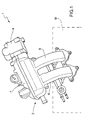
- numeral 1 indicates as a whole an intake system for an internal combustion engine M which intake system 1 comprises an intake manifold 2 and a heat exchanger 3 (shown in figures from 2 to 6) generally known as "intercooler".
- the intake system 1 receives, through a butterfly valve 4, an air flow from a turbocharger (not shown), and feeds this air flow to the cylinders (not shown) of the engine M, when the corresponding pistons (not shown) are at the intake step.
- the intake manifold 2 is connected to the butterfly valve 4 with a sealing ring 5 therebetween and comprises a plurality of intake pipes 6, each of which puts the inside of the intake manifold 2 into communication with a corresponding cylinder (not shown).
- the intake manifold 2 comprises a body 7 displaying an essentially cylindrical tubular shape; and the flow of aspirated air is conveyed, in use, into the body 7 by means of the butterfly valve 4 and exits from the intake pipes 6.
- the heat exchanger 3 is adapted to cool the flow of aspirated air and, thus, to increase the density of the aspirated air itself and is arranged, as shown in figure 3 , inside the body 7 to optimize the dimensions of the intake system 1.
- the heat exchanger 3 comprises an active cooling device surrounding the flow of aspirated air and defined by a cooling circuit 8 using a coolant, and a passive cooling device immersed in the flow of aspirated air and defined by a conduction radiator 9 adapted to be heated by convection by the aspirated air and to transmit by conduction the absorbed heat to the cooling circuit 8.
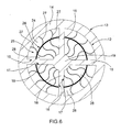
- the cooling circuit 8 comprises a cylindrical tubular body 10, which extends along an axis 11 parallel to an axis of the body 7, is arranged inside the body 7 itself and displays an internal cylindrical wall 12, defining an aspirated air flow passage pipe 12a, and a cylindrical external wall 13, which reciprocally define a tubular chamber 14 having an annular section which is closed at its axial ends.
- the cooling circuit 6 further comprises two diametrical partitions 15 arranged as a cross inside the pipe 12a and integrally connected, along the side edges thereof, to the internal surface of the internal cylindrical wall 12.
- Each partition 15 is defined by two side walls 16 and 17 which are reciprocally parallel and facing each other, and defining a chamber 18 communicating with the other chamber 18 along a central manifold 19 communicating with the chamber 14 along the side edges thereof.
- the cooling circuit 8 finally comprises a pipe 20, which is an outlet pipe of the coolant and is connected to an end of the central manifold 19 facing the butterfly valve 4 and arranged at an air inlet end 21 into the pipe 12a, and a pipe 22, which is a feeding pipe of the coolant and is connected to an end of the central manifold 19, which end is opposite to that facing the butterfly valve 4 and is arranged at an air outlet end 23 of the pipe 12a.
- the partitions 15 define four flow passages 24 for the aspirated air inside the pipe 12a, each of which accommodates a corresponding portion 25 of the radiator 9.
- each portion 25 of the radiator 9 comprises a cylindrical tube sector 26 of about 90° amplitude, extending over the entire length of the tubular body 10, coaxial to the axis 11, and displaying longitudinal side edges integrally connected to the partitions 15 and a diameter of value equal to approximately half the diameter of the external cylindrical wall 13 of the tubular body 10 so as to divide the corresponding flow passage 24 into two parts displaying sections having a surface essentially equal to each other.
- Each portion 25 of the radiator 9 further comprises three radial partitions 27, which are further uniformly distributed about the axis 11, extend from the external surface of the central manifold 19 to the internal surface of the internal wall 12 of the tubular body 10 through the corresponding tube sector 26, are integral with the corresponding tube sector 26 and cooperate with the corresponding sector 26 and with the partitions 15 for dividing the corresponding flow passage 24 into eight channels 28 displaying reciprocally and essentially identical hydraulic resistances.
- the radial partitions 27 are wavy and, thus, also the channels 28 are wavy so as to make the path followed by the aspirated air along the tubular body 10 longer than the axial length of the tubular body 10 itself in order to improve the heat exchange.
- the aspirated air flow is conveyed into the cylindrical tubular body 10 through the inlet end 21 of the pipe 12a, flows into the channels 28 and exits from the outlet end 23 of the pipe 12a.
- the flow of aspirated air releases heat by convection both to the cooling circuit 8 and to the radiator 9, which gives, by convection, the accumulated heat to the cooling circuit 8.
- the heat exchanger 3 is a heat exchanger of the back-flow type, because the motion of the two fluids, i.e. of the aspirated air flow and of the coolant, occurs mainly along the same direction, but in different senses.
- the above-described intake system 1 displays many advantages because it has a compact structure, it is simple and cost-effective to be made and can be mounted indifferently without adopting particular devices both to an aspirated internal combustion engine and to a turbocharged internal combustion engine.
Landscapes
- Engineering & Computer Science (AREA)
- Mechanical Engineering (AREA)
- General Engineering & Computer Science (AREA)
- Physics & Mathematics (AREA)
- Thermal Sciences (AREA)
- Chemical & Material Sciences (AREA)
- Combustion & Propulsion (AREA)
- Geometry (AREA)
- Heat-Exchange Devices With Radiators And Conduit Assemblies (AREA)
Priority Applications (1)
| Application Number | Priority Date | Filing Date | Title |
|---|---|---|---|
| EP08425450A EP2138702A1 (fr) | 2008-06-25 | 2008-06-25 | Système d'entrée pour moteurs à combustion interne |
Applications Claiming Priority (1)
| Application Number | Priority Date | Filing Date | Title |
|---|---|---|---|
| EP08425450A EP2138702A1 (fr) | 2008-06-25 | 2008-06-25 | Système d'entrée pour moteurs à combustion interne |
Publications (1)
| Publication Number | Publication Date |
|---|---|
| EP2138702A1 true EP2138702A1 (fr) | 2009-12-30 |
Family
ID=39876689
Family Applications (1)
| Application Number | Title | Priority Date | Filing Date |
|---|---|---|---|
| EP08425450A Withdrawn EP2138702A1 (fr) | 2008-06-25 | 2008-06-25 | Système d'entrée pour moteurs à combustion interne |
Country Status (1)
| Country | Link |
|---|---|
| EP (1) | EP2138702A1 (fr) |
Cited By (1)
| Publication number | Priority date | Publication date | Assignee | Title |
|---|---|---|---|---|
| CN109844297A (zh) * | 2016-11-04 | 2019-06-04 | 马自达汽车株式会社 | 多缸发动机的进气装置 |
Citations (10)
| Publication number | Priority date | Publication date | Assignee | Title |
|---|---|---|---|---|
| US1874578A (en) * | 1931-04-09 | 1932-08-30 | Sidney A Morrison | Heat exchange device |
| US2434519A (en) * | 1942-04-18 | 1948-01-13 | Raskin Walter | Heat exchange conduit with a spiral fin having a capillary groove |
| WO1983002481A1 (fr) * | 1982-01-13 | 1983-07-21 | Tholen, Paul | Moteur suralimente a combustion interne avec echangeur thermique de l'air de combustion |
| US4476842A (en) * | 1982-09-20 | 1984-10-16 | Allis-Chalmers Corporation | Intercooler damper support |
| WO2000040844A1 (fr) * | 1999-01-08 | 2000-07-13 | Lysholm Technologies Ab | Dispositif d'un moteur a combustion interne a suralimentation |
| EP1170478A2 (fr) * | 2000-07-07 | 2002-01-09 | Volvo Car Corporation | Moteur à combustion avec compresseur, refroidisseur intermédiaire et collecteur d'admission dans un corps coulé monobloc |
| GB2375388A (en) * | 2001-05-10 | 2002-11-13 | Llanelli Radiators Ltd | Heat exchanger arrangement for charge air |
| US20040206340A1 (en) * | 2002-12-13 | 2004-10-21 | Andreas Bilek | Combined intercooler and flame arrester |
| WO2006059215A1 (fr) * | 2004-12-02 | 2006-06-08 | Groppalli S.R.L. | Dispositif de recuperation de la chaleur de gaz de combustion d'une chaudiere domestique |
| WO2008101978A1 (fr) * | 2007-02-23 | 2008-08-28 | Mahle International Gmbh | Module de gaz frais conçu pour une installation de gaz frais |
-
2008
- 2008-06-25 EP EP08425450A patent/EP2138702A1/fr not_active Withdrawn
Patent Citations (10)
| Publication number | Priority date | Publication date | Assignee | Title |
|---|---|---|---|---|
| US1874578A (en) * | 1931-04-09 | 1932-08-30 | Sidney A Morrison | Heat exchange device |
| US2434519A (en) * | 1942-04-18 | 1948-01-13 | Raskin Walter | Heat exchange conduit with a spiral fin having a capillary groove |
| WO1983002481A1 (fr) * | 1982-01-13 | 1983-07-21 | Tholen, Paul | Moteur suralimente a combustion interne avec echangeur thermique de l'air de combustion |
| US4476842A (en) * | 1982-09-20 | 1984-10-16 | Allis-Chalmers Corporation | Intercooler damper support |
| WO2000040844A1 (fr) * | 1999-01-08 | 2000-07-13 | Lysholm Technologies Ab | Dispositif d'un moteur a combustion interne a suralimentation |
| EP1170478A2 (fr) * | 2000-07-07 | 2002-01-09 | Volvo Car Corporation | Moteur à combustion avec compresseur, refroidisseur intermédiaire et collecteur d'admission dans un corps coulé monobloc |
| GB2375388A (en) * | 2001-05-10 | 2002-11-13 | Llanelli Radiators Ltd | Heat exchanger arrangement for charge air |
| US20040206340A1 (en) * | 2002-12-13 | 2004-10-21 | Andreas Bilek | Combined intercooler and flame arrester |
| WO2006059215A1 (fr) * | 2004-12-02 | 2006-06-08 | Groppalli S.R.L. | Dispositif de recuperation de la chaleur de gaz de combustion d'une chaudiere domestique |
| WO2008101978A1 (fr) * | 2007-02-23 | 2008-08-28 | Mahle International Gmbh | Module de gaz frais conçu pour une installation de gaz frais |
Cited By (2)
| Publication number | Priority date | Publication date | Assignee | Title |
|---|---|---|---|---|
| CN109844297A (zh) * | 2016-11-04 | 2019-06-04 | 马自达汽车株式会社 | 多缸发动机的进气装置 |
| EP3514366A4 (fr) * | 2016-11-04 | 2019-11-13 | Mazda Motor Corporation | Dispositif d'admission pour moteur multicylindre |
Similar Documents
| Publication | Publication Date | Title |
|---|---|---|
| US8813728B2 (en) | Intake system for an internal combustion engine | |
| CN103362632B (zh) | 用于内燃机的进气系统 | |
| EP1170478B1 (fr) | Moteur à combustion avec compresseur, refroidisseur intermédiaire et collecteur d'admission dans un corps coulé monobloc | |
| US9488134B2 (en) | Engine system having turbo charger | |
| EP2213857B1 (fr) | Système de refroidissement pour moteur à combustion interne | |
| US20100258096A1 (en) | Intercooler cartridge assembly design for improving internal combustion engine performance | |
| US20080185130A1 (en) | Heat exchanger with extruded cooling tubes | |
| DE60328257D1 (de) | Wärmetauscher | |
| CN106194388B (zh) | 具有冷却液控制阀的发动机系统 | |
| CN108895880B (zh) | 一种用于汽车换热单元集流管内的分流结构 | |
| EP2037200A2 (fr) | Échangeur thermique composé | |
| CN106812624B (zh) | 与排气歧管和egr冷却器成整体的汽缸盖 | |
| EP1788333A1 (fr) | Refroidisseur d'air | |
| CA2585952A1 (fr) | Conduit de raccordement d'un compresseur et d'un refroidisseur intermediaire | |
| CN104340048A (zh) | 混合动力汽车 | |
| EP2138702A1 (fr) | Système d'entrée pour moteurs à combustion interne | |
| CN106870119A (zh) | 一种汽车发动机外挂水冷中冷器及具有其的中冷系统 | |
| CN110630372A (zh) | 热交换器的控制系统 | |
| CN219119351U (zh) | 集成式气缸体水套及发动机 | |
| US20230072542A1 (en) | Compressor for vehicle | |
| CN113464435B (zh) | 压缩机增焓组件、压缩机和空调系统 | |
| KR102726788B1 (ko) | 튜브-핀 어셈블리 | |
| CN218862740U (zh) | 一种增压器执行器冷却结构 | |
| CN224093472U (zh) | 对置发动机冷却系统及汽车 | |
| CN219061869U (zh) | 废气再循环冷却器及废气再循环冷却系统 |
Legal Events
| Date | Code | Title | Description |
|---|---|---|---|
| PUAI | Public reference made under article 153(3) epc to a published international application that has entered the european phase |
Free format text: ORIGINAL CODE: 0009012 |
|
| AK | Designated contracting states |
Kind code of ref document: A1 Designated state(s): AT BE BG CH CY CZ DE DK EE ES FI FR GB GR HR HU IE IS IT LI LT LU LV MC MT NL NO PL PT RO SE SI SK TR |
|
| AX | Request for extension of the european patent |
Extension state: AL BA MK RS |
|
| AKY | No designation fees paid | ||
| REG | Reference to a national code |
Ref country code: DE Ref legal event code: 8566 |
|
| STAA | Information on the status of an ep patent application or granted ep patent |
Free format text: STATUS: THE APPLICATION IS DEEMED TO BE WITHDRAWN |
|
| 18D | Application deemed to be withdrawn |
Effective date: 20100701 |