EP2138728A2 - Tige d'ancre destinée à l'ancrage dans un trou de forage - Google Patents
Tige d'ancre destinée à l'ancrage dans un trou de forage Download PDFInfo
- Publication number
- EP2138728A2 EP2138728A2 EP09163099A EP09163099A EP2138728A2 EP 2138728 A2 EP2138728 A2 EP 2138728A2 EP 09163099 A EP09163099 A EP 09163099A EP 09163099 A EP09163099 A EP 09163099A EP 2138728 A2 EP2138728 A2 EP 2138728A2
- Authority
- EP
- European Patent Office
- Prior art keywords
- anchor rod
- borehole
- composite
- insertion end
- screw portion
- Prior art date
- Legal status (The legal status is an assumption and is not a legal conclusion. Google has not performed a legal analysis and makes no representation as to the accuracy of the status listed.)
- Withdrawn
Links
Images


Classifications
-
- F—MECHANICAL ENGINEERING; LIGHTING; HEATING; WEAPONS; BLASTING
- F16—ENGINEERING ELEMENTS AND UNITS; GENERAL MEASURES FOR PRODUCING AND MAINTAINING EFFECTIVE FUNCTIONING OF MACHINES OR INSTALLATIONS; THERMAL INSULATION IN GENERAL
- F16B—DEVICES FOR FASTENING OR SECURING CONSTRUCTIONAL ELEMENTS OR MACHINE PARTS TOGETHER, e.g. NAILS, BOLTS, CIRCLIPS, CLAMPS, CLIPS OR WEDGES; JOINTS OR JOINTING
- F16B13/00—Dowels or other devices fastened in walls or the like by inserting them in holes made therein for that purpose
- F16B13/14—Non-metallic plugs or sleeves; Use of liquid, loose solid or kneadable material therefor
- F16B13/141—Fixing plugs in holes by the use of settable material
-
- F—MECHANICAL ENGINEERING; LIGHTING; HEATING; WEAPONS; BLASTING
- F16—ENGINEERING ELEMENTS AND UNITS; GENERAL MEASURES FOR PRODUCING AND MAINTAINING EFFECTIVE FUNCTIONING OF MACHINES OR INSTALLATIONS; THERMAL INSULATION IN GENERAL
- F16B—DEVICES FOR FASTENING OR SECURING CONSTRUCTIONAL ELEMENTS OR MACHINE PARTS TOGETHER, e.g. NAILS, BOLTS, CIRCLIPS, CLAMPS, CLIPS OR WEDGES; JOINTS OR JOINTING
- F16B25/00—Screws that cut thread in the body into which they are screwed, e.g. wood screws
-
- F—MECHANICAL ENGINEERING; LIGHTING; HEATING; WEAPONS; BLASTING
- F16—ENGINEERING ELEMENTS AND UNITS; GENERAL MEASURES FOR PRODUCING AND MAINTAINING EFFECTIVE FUNCTIONING OF MACHINES OR INSTALLATIONS; THERMAL INSULATION IN GENERAL
- F16B—DEVICES FOR FASTENING OR SECURING CONSTRUCTIONAL ELEMENTS OR MACHINE PARTS TOGETHER, e.g. NAILS, BOLTS, CIRCLIPS, CLAMPS, CLIPS OR WEDGES; JOINTS OR JOINTING
- F16B5/00—Joining sheets or plates, e.g. panels, to one another or to strips or bars parallel to them
- F16B5/02—Joining sheets or plates, e.g. panels, to one another or to strips or bars parallel to them by means of fastening members using screw-thread
- F16B5/0275—Joining sheets or plates, e.g. panels, to one another or to strips or bars parallel to them by means of fastening members using screw-thread the screw-threaded element having at least two axially separated threaded portions
Definitions
- the invention provides an anchor rod for anchoring in a borehole in an anchoring base, for example concrete, using a hardenable mass which can be introduced into the borehole and hardened there.
- Anchoring of various objects to buildings by means of mortared anchor rods are very common in construction.
- the EP 0 856 669 B1 an anchor rod for a composite expansion anchor having a shaft with a plurality of expansion portions.
- the shaft is anchored by means of a composite mortar in a borehole.
- the power transmission takes place on the one hand by the cohesive action of the composite mortar, on the other hand, but also via a spreading effect of the expansion sections.
- such composite expansion anchors are suitable for demanding anchorages, especially for so-called cracked concrete.
- a disadvantage of the known composite expansion anchors is that the anchor rods can be loaded only after curing of the respective composite mortar, so that an assembly of the objects to be fastened can be done only at a significant time interval after setting the Verbundspreizanker. This not only leads to a time-consuming, but also to a technically complex assembly process of the anchorages. So are For example, in the attachment of crash barriers on highway bridges several operations along the motorway bridge required.
- composite expansion anchors require an elaborate drill hole cleaning, so that the composite mortar can develop its full effect.
- composite expansion anchors also have the disadvantage that, due to the high spreading forces, they are only suitable to a limited extent for near-edge fastenings.
- the invention is based on the idea, for the first time, of several anchoring concepts in a single anchor rod unite and thus create a kind of "hybrid anchor rod".
- the invention provides that the shaft of the anchor rod at least one composite expansion portion, the extent of which at least partially extends towards an insertion end of the shaft, and at least one screw portion whose circumference is provided with a thread, which is provided in engaging the wall of a borehole.
- an anchor rod in which immediately after the insertion of the anchor rod into a borehole a mounting torque can be applied, since this is taken up by the at least one screw portion.
- the at least one screw section allows a more constant annular gap in the region of the at least one composite spreading section, so that an optimum composite area results.
- the composite area not only causes a good support and Nachsp Son , but also protects the anchor rod or an entire mounting arrangement from the ingress of moisture, which significantly improves the durability.
- the anchor rod according to the invention has a simple construction, since for many applications a short screw section is sufficient, so that not the entire anchor rod must be provided with a complex thread.
- At least one screw section is located between the insertion end and a composite expansion section.
- At least one screw section is located on the opposite side of the insertion of the Verbundspreizabitess. This results in a particularly precise alignment of the anchor rod with uniform annular gap, uniform distribution of the anchoring forces and optionally a compression of the hardenable mass.
- At least one composite expansion section has a plurality of conical expansion sections, the circumference of which widens in each case at least partially in the direction of the insertion end.
- the number of conical expanding sections is not particularly limited within the scope of the invention, however, the use of at least three conical expansion sections has proven to be particularly effective.
- the length of the conical expansion sections in the context of the invention can be varied in many ways, although a length has proven advantageous, which corresponds approximately to the nominal diameter of the screw portion.
- At least one composite spreading section has a coating or covering at least in sections.
- a coating or covering at least in sections.
- the wrapping may, for example, be a shrink tube, although here too many other configurations are possible.
- the screw portion may be configured in the context of the present invention in various ways and, if appropriate, also designed to be screwed into a thread already present in the concrete.
- at least one screw portion has a self-tapping thread.
- At least one screw section can be varied in many ways within the scope of the present invention. According to one embodiment of the invention, however, it is provided that at least one screw portion in a direction of extension of the anchor rod has a length which corresponds to at least 1.0 times and preferably at most 5.0 times the nominal diameter of the screw portion. In this way, there is a slight screwing of the anchor rod, while at the same time a sufficient biasing torque can be applied. In this case, a range of 1.5 to 3.0 has proven to be particularly effective for the length of the anchor rod with respect to the nominal diameter of the screw portion.
- At least one screw portion in particular one between the insertion and a Composite spreading portion located screw portion, guiding means for conducting a curable composition in a longitudinal direction of the anchor rod away from the insertion end.
- the guiding means can be designed in various ways in the context of the invention and, for example, also comprise a surface coating, as has already been described above. According to one embodiment of the invention, however, it is provided that the guide means helical depressions in the surface of the screw portion and / or at least one passage opening in the shaft of the anchor rod, which preferably opens from the insertion end in a composite spreading. This results in a simple design effective forwarding of the hardenable mass from the insertion end of the anchor rod to the composite expansion section with a correspondingly low insertion torque and good filling of the annular gap.
- the present invention provides a fastening arrangement according to claim 10, by which the above-mentioned advantages can be realized particularly pronounced.
- the hardenable mass can completely fill the annular gap around the anchor rod or can also be arranged only in partial regions of the annular gap.
- the hardenable mass is provided at least in the area of the composite spreading section. In this way, virtually all inventive advantages can be achieved with minimal material consumption and minimal insertion torque.
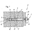
- the fastening arrangement 8 comprises an anchor rod 1 which is anchored via a hardenable mass 6 in a borehole 2 in an anchoring base 4.
- the anchoring base 4 may be, for example, concrete, but also to other building materials such as brick and possibly also wood, plastic, etc. act.
- the hardenable mass 6 which may be, for example, a mortar Eypoxidharz or vinyl ester with fine-grained aggregates).
- the anchor rod 1 has a shaft 10 with an insertion end 12, which is arranged in the installed state at the bottom of the borehole hole 2. Further, in the present embodiment, the shaft 10 has a composite expanding portion 14 and a screw portion 18 located between the insertion end 12 and the composite expanding portion 14.
- the composite spreading portion 14 has, in the present embodiment, three conical expanding portions 14 ', the periphery of which widens toward the insertion end 12 respectively. It should be noted, however, that the number and precise configuration of the conical spreading portions 14 'in the context of the present invention is not limited. In this case, the composite spreading portion 14 may also have a coating or cladding, although this is not shown in the figures.
- the screw portion 18 ' is designed in the present embodiment as a self-tapping thread, which is designed to engage when screwing the anchor rod 1 into the borehole 2 in the borehole wall 2' and leave there threads that in Fig. 1 are indicated schematically. This results in that the thread 18 'of the screw portion 18 in the assembled state of the anchor rod 1 partially engages positively in the surrounding anchoring ground 4.
- the lengths of the screw portion 18 and the composite expanding portion 14, measured in the extending direction of the shaft 10, can be varied widely within the scope of the present invention.
- the screw portion 18 in the present embodiment has a length in the extension direction of the anchor rod 10, which is about 1.5 to 3.0 times the nominal diameter of the screw portion 18 corresponds.
- the assembly process of the anchor rod 1 in the anchoring ground 4 takes place, for example, as follows. First, a borehole 2 is created in the anchoring ground 4, for example by means of a suitable hammer drill. Subsequently, the hardenable mass 6 is introduced into the wellbore 4, wherein the amount of the hardenable mass 6 to be introduced is designed such that in the assembled state of the anchor rod, the curable mass 6 is provided functionally at least in the region of the at least one Verbundspreizabitess 14 or all Verbundspreizabête.
- the anchor rod 1 is inserted with its insertion end 12 in the borehole 2 and screwed, for example by means of a rotating tool in the borehole 2.
- the screw section 18 generates thread-like depressions in the borehole wall 2 '.
- the screw section 18 also reaches the hardenable mass 6 introduced into the borehole 2, it is conveyed through the threads of the thread 18 towards the composite spreading section 14 and possibly further to the mouth of the borehole 2, so that the annular gap 2 " between the shaft 10 and the borehole wall 2 'is filled with the curable composition 6.
- an attachment 28 can be placed over the shank 10 of the anchor rod 1 and fastened by means of a nut 24 and a thread 26 provided on the shank 10.
- a nut 24 and a thread 26 provided on the shank 10.
- FIG Fig. 2 A second preferred embodiment of the fastening arrangement 8 according to the invention or the anchor rod 1 according to the invention is shown in FIG Fig. 2 shown schematically. This is different from the one in Fig. 1 embodiment shown primarily in that the anchor rod 1 adjacent to the insertion end 12 has a second composite expansion portion 16, which is designed similar to the first composite expansion portion 14 in the present embodiment.
- the second embodiment is the same in construction and mounting of the first embodiment, and a repeated description thereof will be omitted.
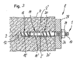
- FIG Fig. 3 A third preferred embodiment of the fastening arrangement 8 according to the invention or of the anchor rod 1 according to the invention is shown in FIG Fig. 3 shown schematically. This is different from the one in Fig. 1 shown embodiment in that it further comprises a second threaded portion 20 which is disposed between the composite expanding portion 14 and the thread 26 of the shaft 10.
- the second embodiment is the same in construction and mounting of the first embodiment, and a repeated description thereof will be omitted.
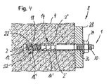
- a fourth preferred embodiment of the fastening arrangement 8 according to the invention or the invention Anchor rod 1 is in Fig. 4 shown schematically.
- the screw section 18 located between the insertion end 12 and the composite spreading section 14 has conducting means 22 for guiding the hardenable mass 6 towards the composite spreading section 14.
- the guide means 22 are formed in the present embodiment as a helical depressions 22 'in the surface of the screw portion 18. In this way it is possible that even with more viscous or coarse-grained curable masses 6, a reliable and rapid transport of the hardenable mass 6 can be carried out to the composite spreading portion 14 or other Verbundspreizabites.
- the second embodiment is the same in construction and mounting of the first embodiment, and a repeated description thereof will be omitted.
- FIG. 5 schematically showing a fifth preferred embodiment of the fastening arrangement 8 according to the invention or the anchor rod 1 according to the invention.
- the guide means 22 are formed as a passage opening 22 "in the shaft 10 of the anchor rod 1, wherein the passage opening extends from the insertion end and opens in the region of the Verbundspreizabitess 14.
- This can also be an improved or more reliable promotion of the curable composition towards the Verbundspreizabêt 14 or other Verbundspreizabitesen be achieved
- Fig. 4 and Fig. 5 shown conducting means can also be combined with each other, and that other embodiments are possible.
Landscapes
- Engineering & Computer Science (AREA)
- General Engineering & Computer Science (AREA)
- Mechanical Engineering (AREA)
- Joining Of Building Structures In Genera (AREA)
- Piles And Underground Anchors (AREA)
Applications Claiming Priority (1)
| Application Number | Priority Date | Filing Date | Title |
|---|---|---|---|
| DE102008030051A DE102008030051B4 (de) | 2008-06-25 | 2008-06-25 | Ankerstange zur Verankerung in einem Bohrloch |
Related Parent Applications (1)
| Application Number | Title | Priority Date | Filing Date |
|---|---|---|---|
| DE102008030051 Previously-Filed-Application | 2008-06-25 |
Publications (2)
| Publication Number | Publication Date |
|---|---|
| EP2138728A2 true EP2138728A2 (fr) | 2009-12-30 |
| EP2138728A3 EP2138728A3 (fr) | 2010-11-17 |
Family
ID=41189338
Family Applications (1)
| Application Number | Title | Priority Date | Filing Date |
|---|---|---|---|
| EP09163099A Withdrawn EP2138728A3 (fr) | 2008-06-25 | 2009-06-18 | Tige d'ancre destinée à l'ancrage dans un trou de forage |
Country Status (2)
| Country | Link |
|---|---|
| EP (1) | EP2138728A3 (fr) |
| DE (1) | DE102008030051B4 (fr) |
Cited By (3)
| Publication number | Priority date | Publication date | Assignee | Title |
|---|---|---|---|---|
| EP3940250A1 (fr) | 2020-07-14 | 2022-01-19 | Hilti Aktiengesellschaft | Vis hybride dotée d'une zone tampon |
| EP3940248A1 (fr) | 2020-07-14 | 2022-01-19 | Hilti Aktiengesellschaft | Vis hybride, dont le filetage s'étend plus en arrière que la cale |
| EP3940249A1 (fr) | 2020-07-14 | 2022-01-19 | Hilti Aktiengesellschaft | Vis hybride avec rainure de cale compartimentée |
Families Citing this family (1)
| Publication number | Priority date | Publication date | Assignee | Title |
|---|---|---|---|---|
| DE102011006455A1 (de) * | 2011-03-30 | 2012-10-04 | TOGE-Dübel A. Gerhard KG | Befestigungs-Anker sowie Befestigungs-Anker-Anordnung |
Family Cites Families (7)
| Publication number | Priority date | Publication date | Assignee | Title |
|---|---|---|---|---|
| SE407435B (sv) * | 1976-08-12 | 1979-03-26 | Atomenergi Ab | Forfarande for fastsettning av en bergbult |
| DE19704002A1 (de) | 1997-02-04 | 1998-08-06 | Hilti Ag | Ankerstange für Verbundanker |
| DE19841135A1 (de) | 1997-09-25 | 1999-04-01 | Toge Duebel A Gerhard Kg | Betonschraube |
| DE19820671A1 (de) | 1998-05-08 | 1999-11-11 | Fischer Artur Werke Gmbh | Selbstschneidende Schraube zum Einsatz in Vollbaustoffen |
| DE29815614U1 (de) * | 1998-09-02 | 2000-01-13 | Wieland Engineering Ag, Maienfeld | Verbundschraube für ein Holz-Beton-Tragwerk |
| DE10311471A1 (de) * | 2003-03-15 | 2004-09-23 | Fischerwerke Artur Fischer Gmbh & Co. Kg | Gewindeformende Schraube für Untergründe aus harten Vollbaustoffen |
| DE102006004555A1 (de) * | 2006-01-27 | 2007-08-02 | Swg Schraubenwerk Gaisbach Gmbh | Schraube |
-
2008
- 2008-06-25 DE DE102008030051A patent/DE102008030051B4/de not_active Expired - Fee Related
-
2009
- 2009-06-18 EP EP09163099A patent/EP2138728A3/fr not_active Withdrawn
Cited By (7)
| Publication number | Priority date | Publication date | Assignee | Title |
|---|---|---|---|---|
| EP3940250A1 (fr) | 2020-07-14 | 2022-01-19 | Hilti Aktiengesellschaft | Vis hybride dotée d'une zone tampon |
| EP3940248A1 (fr) | 2020-07-14 | 2022-01-19 | Hilti Aktiengesellschaft | Vis hybride, dont le filetage s'étend plus en arrière que la cale |
| EP3940249A1 (fr) | 2020-07-14 | 2022-01-19 | Hilti Aktiengesellschaft | Vis hybride avec rainure de cale compartimentée |
| WO2022012974A1 (fr) | 2020-07-14 | 2022-01-20 | Hilti Aktiengesellschaft | Vis hybride à rainure biseautée compartimentée |
| WO2022012975A1 (fr) | 2020-07-14 | 2022-01-20 | Hilti Aktiengesellschaft | Vis hybride dont le filet s'étend plus loin vers l'arrière qu'une partie biseautée |
| WO2022012976A1 (fr) | 2020-07-14 | 2022-01-20 | Hilti Aktiengesellschaft | Vis hybride à zone tampon |
| US12292071B2 (en) | 2020-07-14 | 2025-05-06 | Hilti Aktiengesellschaft | Hybrid screw with compartmentalized wedge groove |
Also Published As
| Publication number | Publication date |
|---|---|
| DE102008030051B4 (de) | 2010-10-07 |
| DE102008030051A1 (de) | 2010-01-07 |
| EP2138728A3 (fr) | 2010-11-17 |
Similar Documents
| Publication | Publication Date | Title |
|---|---|---|
| EP2257690B1 (fr) | Cheville autoforeuse protégée contre la corrosion, et bloc d'éléments de cheville, et leur procédé de fabrication | |
| EP1892425A2 (fr) | Elément de fixation pour des supports durs | |
| EP2250380B1 (fr) | Système constitué d'une vis d'ancrage composite et d'un adhésif | |
| EP1905923A2 (fr) | Tige d'ancrage et dispositif destiné au renforcement de composants existants contre le cisaillement à l'aide d'une telle tige d'ancrage | |
| DE102004020852B4 (de) | Eingussdübel | |
| EP2284405B1 (fr) | Agencement de fixation | |
| EP2354567B1 (fr) | Vis de tige d'encrage | |
| DE102008030051B4 (de) | Ankerstange zur Verankerung in einem Bohrloch | |
| EP2581611A1 (fr) | Agencement de fixation doté d'une vis bifonctionnelle | |
| DE19513202A1 (de) | Vorrichtung zur Verankerung von Bewehrungs- bzw. Spannstählen in Verankerungsgründen | |
| DE102006017459A1 (de) | Abstandshalter für die Befestigung eines Gegenstandes an einem eine Dämmschicht aufweisenden Untergrund | |
| EP2893139B1 (fr) | Ensemble d'ancrage haute résistance d'un élément de précontrainte dans une pièce, l'élément de précontrainte comportant une tige de précontrainte, et procédé de production dudit ancrage | |
| WO2012152237A1 (fr) | Vis d'ancrage composite | |
| DE10311471A1 (de) | Gewindeformende Schraube für Untergründe aus harten Vollbaustoffen | |
| EP2977528A1 (fr) | Systeme de renfort d'un ouvrage et procede destine a renforcer un ouvrage dote d'un tel systeme de renfort | |
| EP1753916A1 (fr) | Dispositif d'ancrage, barre d'ancrage et procede de fabrication d'un dispositif d'ancrage | |
| EP2251555A1 (fr) | Cheville | |
| EP2009296B1 (fr) | Elément de fixation ancrable chimiquement | |
| EP1706653B1 (fr) | Element d'ancrage et utilisation d'un boulon d'ancrage | |
| DE102007043568A1 (de) | Befestigungselement für Lochbaustoffe | |
| EP0697530A1 (fr) | Boulon d'ancrage pour béton ou similaire | |
| DE2201950B2 (de) | Verpreßanker zum Verankern von Bauteilen in erdigem oder felsigem Baugrund | |
| DE3339339A1 (de) | Verpressanker und verfahren zu seinem herstellen und einbauen | |
| DE19648931A1 (de) | Anker für Beton oder dergleichen | |
| EP4673613A1 (fr) | Procédé de fabrication d'un plancher composite bois-béton, plancher composite bois-béton, vis et pièce de marquage |
Legal Events
| Date | Code | Title | Description |
|---|---|---|---|
| PUAI | Public reference made under article 153(3) epc to a published international application that has entered the european phase |
Free format text: ORIGINAL CODE: 0009012 |
|
| AK | Designated contracting states |
Kind code of ref document: A2 Designated state(s): AT BE BG CH CY CZ DE DK EE ES FI FR GB GR HR HU IE IS IT LI LT LU LV MC MK MT NL NO PL PT RO SE SI SK TR |
|
| RAP1 | Party data changed (applicant data changed or rights of an application transferred) |
Owner name: WUERTH INTERNATIONAL AG Owner name: ADOLF WUERTH GMBH & CO. KG |
|
| PUAL | Search report despatched |
Free format text: ORIGINAL CODE: 0009013 |
|
| AK | Designated contracting states |
Kind code of ref document: A3 Designated state(s): AT BE BG CH CY CZ DE DK EE ES FI FR GB GR HR HU IE IS IT LI LT LU LV MC MK MT NL NO PL PT RO SE SI SK TR |
|
| AX | Request for extension of the european patent |
Extension state: AL BA RS |
|
| 17P | Request for examination filed |
Effective date: 20110517 |
|
| 17Q | First examination report despatched |
Effective date: 20140804 |
|
| STAA | Information on the status of an ep patent application or granted ep patent |
Free format text: STATUS: THE APPLICATION IS DEEMED TO BE WITHDRAWN |
|
| 18D | Application deemed to be withdrawn |
Effective date: 20141216 |