EP2138775A2 - Agencement et procédé de préparation d'eau potable chaude à l'aide de caloporteur - Google Patents
Agencement et procédé de préparation d'eau potable chaude à l'aide de caloporteur Download PDFInfo
- Publication number
- EP2138775A2 EP2138775A2 EP09157072A EP09157072A EP2138775A2 EP 2138775 A2 EP2138775 A2 EP 2138775A2 EP 09157072 A EP09157072 A EP 09157072A EP 09157072 A EP09157072 A EP 09157072A EP 2138775 A2 EP2138775 A2 EP 2138775A2
- Authority
- EP
- European Patent Office
- Prior art keywords
- fluid
- drinking water
- heat exchanger
- circuit
- primary
- Prior art date
- Legal status (The legal status is an assumption and is not a legal conclusion. Google has not performed a legal analysis and makes no representation as to the accuracy of the status listed.)
- Withdrawn
Links
Images

Classifications
-
- F—MECHANICAL ENGINEERING; LIGHTING; HEATING; WEAPONS; BLASTING
- F24—HEATING; RANGES; VENTILATING
- F24D—DOMESTIC- OR SPACE-HEATING SYSTEMS, e.g. CENTRAL HEATING SYSTEMS; DOMESTIC HOT-WATER SUPPLY SYSTEMS; ELEMENTS OR COMPONENTS THEREFOR
- F24D17/00—Domestic hot-water supply systems
- F24D17/0078—Recirculation systems
-
- F—MECHANICAL ENGINEERING; LIGHTING; HEATING; WEAPONS; BLASTING
- F24—HEATING; RANGES; VENTILATING
- F24D—DOMESTIC- OR SPACE-HEATING SYSTEMS, e.g. CENTRAL HEATING SYSTEMS; DOMESTIC HOT-WATER SUPPLY SYSTEMS; ELEMENTS OR COMPONENTS THEREFOR
- F24D17/00—Domestic hot-water supply systems
- F24D17/0026—Domestic hot-water supply systems with conventional heating means
- F24D17/0031—Domestic hot-water supply systems with conventional heating means with accumulation of the heated water
-
- F—MECHANICAL ENGINEERING; LIGHTING; HEATING; WEAPONS; BLASTING
- F24—HEATING; RANGES; VENTILATING
- F24D—DOMESTIC- OR SPACE-HEATING SYSTEMS, e.g. CENTRAL HEATING SYSTEMS; DOMESTIC HOT-WATER SUPPLY SYSTEMS; ELEMENTS OR COMPONENTS THEREFOR
- F24D17/00—Domestic hot-water supply systems
- F24D17/0073—Arrangements for preventing the occurrence or proliferation of microorganisms in the water
-
- F—MECHANICAL ENGINEERING; LIGHTING; HEATING; WEAPONS; BLASTING
- F24—HEATING; RANGES; VENTILATING
- F24D—DOMESTIC- OR SPACE-HEATING SYSTEMS, e.g. CENTRAL HEATING SYSTEMS; DOMESTIC HOT-WATER SUPPLY SYSTEMS; ELEMENTS OR COMPONENTS THEREFOR
- F24D19/00—Details
- F24D19/10—Arrangement or mounting of control or safety devices
- F24D19/1006—Arrangement or mounting of control or safety devices for water heating systems
- F24D19/1051—Arrangement or mounting of control or safety devices for water heating systems for domestic hot water
-
- Y—GENERAL TAGGING OF NEW TECHNOLOGICAL DEVELOPMENTS; GENERAL TAGGING OF CROSS-SECTIONAL TECHNOLOGIES SPANNING OVER SEVERAL SECTIONS OF THE IPC; TECHNICAL SUBJECTS COVERED BY FORMER USPC CROSS-REFERENCE ART COLLECTIONS [XRACs] AND DIGESTS
- Y02—TECHNOLOGIES OR APPLICATIONS FOR MITIGATION OR ADAPTATION AGAINST CLIMATE CHANGE
- Y02B—CLIMATE CHANGE MITIGATION TECHNOLOGIES RELATED TO BUILDINGS, e.g. HOUSING, HOUSE APPLIANCES OR RELATED END-USER APPLICATIONS
- Y02B10/00—Integration of renewable energy sources in buildings
- Y02B10/20—Solar thermal
-
- Y—GENERAL TAGGING OF NEW TECHNOLOGICAL DEVELOPMENTS; GENERAL TAGGING OF CROSS-SECTIONAL TECHNOLOGIES SPANNING OVER SEVERAL SECTIONS OF THE IPC; TECHNICAL SUBJECTS COVERED BY FORMER USPC CROSS-REFERENCE ART COLLECTIONS [XRACs] AND DIGESTS
- Y02—TECHNOLOGIES OR APPLICATIONS FOR MITIGATION OR ADAPTATION AGAINST CLIMATE CHANGE
- Y02B—CLIMATE CHANGE MITIGATION TECHNOLOGIES RELATED TO BUILDINGS, e.g. HOUSING, HOUSE APPLIANCES OR RELATED END-USER APPLICATIONS
- Y02B10/00—Integration of renewable energy sources in buildings
- Y02B10/70—Hybrid systems, e.g. uninterruptible or back-up power supplies integrating renewable energies
Definitions
- the invention relates to an arrangement for providing warm drinking water with a primary circuit with a fluid, a hot or hot fluid-providing device having a buffer memory with temperature-dependent stratified areas of the primary fluid, and a conveyor for the fluid, with a secondary circuit for the drinking water to be heated with a heat exchanger for transferring heat from the fluid of the primary circuit to the drinking water in the secondary circuit, with a line in the primary circuit, which returns fluid from the heat exchanger to the device, with a control device for the conveyor, and with at least one temperature sensor in the primary circuit or secondary circuit, the measured values be supplied to the control device.
- the invention also relates to a method for providing warm drinking water in such plants.
- an economically much more meaningful and at the same time more environmentally friendly solution can be found in systems that work with a drinking water storage tank.
- an additional storage tank is provided, can be stored in the hot water.
- the drinking water storage tank is sized so that it is readily capable of covering peak loads.
- the heat generation can here be made significantly smaller, in order to replace spontaneously with peak load consumed hot drinking water over a longer period again.
- a high hot water comfort can be provided.
- the contents of the storage tank must always be kept at a minimum of 60 ° C to avoid hygienic risks.
- high temperatures are not economically viable, especially since they can then no longer be combined with solar systems, condensing boilers and the like.
- the drinking water storage must also be performed corrosion resistant, such as enameled steel or stainless steel, which leads to more expensive systems and also requires a considerable amount of space.
- a primary fluid is provided in a heater side, for example buffer memory, said buffer approximately as from the EP 0 384 423 B1 known layered memory can be constructed.
- the heat generation in this primary fluid can be done in any form by solar heating, geothermal, cogeneration, solid fuel boilers, etc. Hygienically, these primary fluid circuits are not critical because the primary fluid is not used as drinking water and may also contain any additives.
- a hot water station which has a heat exchanger, for example a plate heat exchanger, can be connected to the buffer tank. If necessary, the primary fluid flows through this heat exchanger and discharges in it the required heat to the drinking water to be heated.
- a heat exchanger for example a plate heat exchanger
- Such systems are very hygienic, have a relatively small footprint, since the buffer for the heating system is needed anyway, and are usually relatively inexpensive to manufacture.
- the line of the primary circuit in the region between the heat exchanger and the device has a plurality of parallel strands, that in each of the parallel strands at least one conveyor is arranged, that the plurality of parallel strands of the line respectively sandwiching the fluid into regions of the buffer reservoir of the device that have a different temperature, and that the control of the delivery devices in the parallel strands by the control device is possible differently depending on the determined temperature of the fluid in the conduit for each delivery device.
- This object is achieved in a generic method according to the invention in that the fluid of the primary circuit is performed in the region between the heat exchanger and the device in several parallel strands that each of these parallel strands makes a separate promotion of the fluid that the fluids from the parallel Strands are stacked in areas of the buffer memory of the device with different temperature, and that the control of the conveyors in the parallel strands are controlled differently by the control device depending on the detected temperature of the fluid in the conduit for each conveyor.
- a division of the return flow of the primary fluid from the heat exchanger to at least two different flow paths now takes place.
- Each of these two flow paths contains a conveying device, in particular a circulating pump, which is in particular speed-controlled.
- These two (or more) circulation pumps run independently of each other.
- In each of the two sub-strands is now preferably a pump.
- These pumps may be provided with a downstream check valve to prevent mis-circulation.
- parallel strands is of course not to be understood in the strict geometric sense, but fluidically so that these two strands form parts of the line from the heat exchanger to the device and alternatives for the way that can take a molecule of the primary fluid.
- the hot or hot fluid-providing device has a buffer memory with temperature-dependent stratified areas of the primary fluid and if the plurality of parallel strands of the line respectively embed the fluid in areas of the buffer memory of the device which have a different temperature.
- the primary fluid in the heat exchanger is a very large part of its heat energy taken.
- the primary fluid thus leaves the heat exchanger in a relatively cold state. It is then passed through one of the two sub-strands, namely by the partial strand provided for cold primary fluid back into the store and there layered directly into the lower area.
- the primary fluid In the buffer reservoir, the primary fluid is normally in a stratified form, with the colder areas of the primary fluid at the bottom and the warmer areas of the primary fluid at the top of the buffer, corresponding to the density distributions of the primary fluid.
- feeding the cold primary fluid into the lower region does not disturb this stratification.
- the circulating pump in this cold sub-string is dimensioned according to the peak power in the dispensing operation, which is usually much larger than the circulation capacity. However, this peak power is much less frequently called as the circulation power.
- the primary fluid flow occurring in this case is now passed through the second partial strand.
- the pump of this sub-string can be designed much smaller than the first-mentioned pump usually.
- the design corresponds to a normal circulation load. Due to the expected long pump running times, speed-controllable high-efficiency pumps with EC motors should be used here in particular.
- This second sub-string is led into the storage area about the same temperature.
- the significantly warmer primary fluid matches its temperature exactly in this area of the stratified primary fluid quantities.
- This temperature-dependent stratification can be approximately due to the EP 0 384 423 B! be produced known layers or elements.
- a circulation circuit is provided for the secondary circuit, which has a conveyor, if the conveyor is equipped to promote a variable volume flow, and if the circulation circuit is designed so that it constantly provides already heated drinking water to a hot water outlet of the secondary circuit ,
- the conveyor is connected to the control device and if the control device actively influences a promotion of the volume flow in the circulation circuit to achieve a high control quality of hot water outlet and / or to prevent stagnation in the secondary circuit for Verkaltungsvorbefingung.
- variable setting of the volume flows makes it possible to achieve outlet temperatures at a hot water outlet in a targeted manner.
- the specific return temperature as well as the volume flows of the drinking water and the circulating water can be detected by corresponding sensors. This allows the two (or more) To control conveyors in the different strands as needed.
- Also on the side of the primary circuit sensors can be provided which detect the temperature and / or the flow rate.
- a temperature sensor in the return line from the heat exchanger to the device can be used, which measures directly whether now just strongly or less strongly cooled primary fluid flows in the line. If this temperature sensor or, to put it concretely, the control device connected to it detects a change in temperature, then it switches to the other pump in each case.
- volume flow measuring devices can also be used. Although it is possible to provide a control even without volume flow measuring devices, but this improves the possibilities, for example, to show an energy demand.
- a separate temperature sensor in the return line is dispensed with, and measured values which a temperature sensor recognizes in the secondary circuit are used instead. This determines whether hot water is being tapped right now or not.
- a separate temperature sensor in the return line is dispensed with, and measured values which a temperature sensor recognizes in the secondary circuit are used instead. This determines whether hot water is being tapped right now or not.
- such an embodiment is used only in special cases.
- a control device recognizes whether and which temperature and which volume flows in the return line of the primary fluid can be consistently determined from this knowledge so that it can also decide which of the two pumps in the partial strands should just run.
- the invention relies in particular on a combination of a buffer memory on the one hand and a certain form of direct pass on the other hand.
- the heating of the drinking water as well as the circulation volume flow to the desired hot water temperature takes place via a heat exchanger, such as a plate heat exchanger, in a continuous process.
- a separate drinking water storage is not required according to the invention.
- the various components can be kept very handy in standardized form, such as in prefabricated stations in conjunction with a corresponding system control. With an identical system structure, different stations from different desired performance classes can be provided right down to the megawatt range.
- the buffer with its temperature-dependent layers can fully exploit its advantages and work as energy storage with fluctuating loads for drinking water and heating as well as fluctuating profits such as from a solar system.
- the system can be used particularly expediently with a buffer store, in which the primary fluid is at the same time heating water, ie at a buffer storage or buffer stratified storage tank filled with heating water.
- the valuable and always well-monitored food Drinking water is warmed just as it is being used, resulting in excellent hygienic properties.
- the content of the drinking water heater is reduced to one minium.
- the primary-side return flow rates are separated clean temperature-oriented, which can be realized very quickly by a corresponding sensor. This leads to a rapid and long-lasting cooling of the lower buffer area in the tap of drinking water. This is effective and this cold volume can be used for a time-delayed Nachfilvorgang also to an active control of the return temperature. Desired target temperatures can be controlled very precisely and the cold volume is at the same time available for increasing the system efficiency during solar heating.
- the temperature can be detected directly within the heat exchanger. This more direct information helps fluctuating hot water temperatures, in particular to avoid load changes and to achieve a precise control and regulation. In this way, it is also possible to measure whether, in the case of tapping stops in the heat exchanger, a temperature which is critical for calcification can be achieved by the transfer of residual heat to the primary fluid side.
- a circulation pump is used, which is also part of the station. It can preferably be speed-controlled directly by the control. Through this active operation of the circulation pump on the secondary or drinking water side a uniform hot water temperature is reached.
- the heat exchanger in particular a plate heat exchanger, is continuously flowed through. With an appropriate pump control, temperatures on the drinking water side of more than 60 ° can be avoided. This also gives active calcification prevention.
- the invention can also be used in drinking water systems without a circulation network. There, an outlet in the hot water pipe with return via the circulation connection of the station can be provided.
- a load-dependent flow through the heat exchanger in particular so a plate heat exchanger, allows. This allows an adapted use of the available plates and thus an optimal heat transfer with a minimization of the return temperature.
- plate heat exchangers are often operated in a very large power range. They then have to be designed for the peak load case. For a light load case, however, such a plate heat exchanger is then oversized.
- the plate heat exchanger consisting of a plurality of plates connected in parallel becomes then flows through each of the fluids at a relatively low flow rate. As a result, the heat transfer and thus also the effectiveness of the heat transfer deteriorates. The return temperature rises.
- the wiring of the plates in the interior of the plate heat exchanger is made load-dependent.
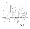
- FIG. 1 The purely schematic, only the most essential parts of the entire arrangement reproducing representation in FIG. 1 shows in the left half of a primary circuit 10, in the right half of a secondary circuit 20. A certain area of the arrangement shown is summarized with dashed lines as a heat station 1. This can be prefabricated to simplify assembly.
- the primary circuit 10 starts on the left with a device that provides hot or hot fluid, here a buffer memory 11. From this buffer memory 11, a line 12 leads to a heat exchanger 50. After passing through the heat exchanger 50 and the release of heat energy in the same runs the Fluid in the primary circuit 10 back via an output-side line 13 to the device 11, ie the buffer memory.
- a conveyor 14 in particular a pump is provided.
- the fluid passes from the upper region of the buffer memory 11 to the heat exchanger 50, from there through the line 13 then back into the lower region of the buffer memory 11, where it is layered or otherwise returned suitable.
- the secondary circuit 20 on the right side of the representation of FIG. 1 begins with a cold water supply line 22, with the cold drinking water (drinking water, washing water, etc.) is supplied to the heat exchanger 50.
- the heat energy of the current in countercurrent primary circuit 10 is received.
- the drinking water leaves the latter again and flows through an outlet-side line 23 to the hot water extraction point, the tapping point.
- the promotion in the secondary circuit can in principle be effected by the fact that the cold water supply is under pressure and the hot water extraction point by a cock locks this pressure if necessary.
- a circulation line 40 is provided in the secondary circuit 20.
- the circulation line 40 branches adjacent to the tapping point (not shown, right outside the heat station 1) and leads back to the cold water access line 22 immediately before the heat exchanger 50.
- a circulation conveyor 44 is provided in the form of a circulation pump. Also indicated is a temperature sensor 47 which measures the temperature in the circulation line 40.
- thermosensor 47 In addition to the temperature sensor 47, other sensor elements may be provided (not shown), such as a volumetric flow meter, in order to better detect the circulation load.
- the volume flow device or preferably the output signal of a temperature sensor 57 in the heat exchanger 50 gives a signal for the circulation pump 44, the drinking water in line 23 is out of the range deduct before the tap and promote through the circulation line 40 back in front of the heat exchanger 50.
- a control device 30 which will be discussed below is made possible, to adjust the tapping temperature constant and, if necessary, to detect the amount of heat delivered.
- the purpose of the circulation circuit 40 is not to let the cooled water after a certain time in the line 23 to flow out of the tap because the consumer wants there warm water and not cooled drinking water. He would not use this not wanted by him cooled drinking water and possibly just run off the line.
- the water currently flowing out of the heat exchanger 50 is warm because it has received heat energy from the primary circuit 10.
- the length of the line 23 and the flow behavior are known, so that very precisely the circulation pump 44 can be controlled so that exactly when it reaches desired heated drinking water at the tap this can also escape there.
- Temperature control values from the temperature sensors 47 or 57 or 27 can therefore be used for a control (or, more precisely, control or activation) of the delivery devices 14a, 14b, 14c, as well as measured values of volume flow measurements or other measured values which allow conclusions to be drawn about the current situation present situation or current load behavior.
- a control device 30 is indicated only schematically. This regulating device 30 is now connected to the conveying devices 14a, 14b, 14c and the temperature sensors 27, 47, 57 with data transmission lines, not shown, in order, on the one hand, to receive measured values and, on the other hand, to transmit corresponding control or regulating signals.
- a power supply for the conveyors 14a, 14b, 14c may be provided.
- each of these three branch lines 13a, 13b, 13c are each a conveyor 14a, 14b, 14c.
- These three conveyors are preferably pumps and are independent of one another and can be of different types and in particular of variably variable delivery rates.
- This buffer memory 11 is constructed as a layered memory, so that, as already mentioned above, the warmer areas of the primary fluid are higher up and the colder ones are further down.
- one of the conveyors 14 is turned on and the other two branches are blocked accordingly. Through this then no fluid flows or the fluid is in them.
- Relatively warm primary fluid in the conduit 13 is also conveyed into an area of the buffer accumulator 11 further up by switching on the uppermost conveyor 14c.
- the temperature of the primary fluid after exiting the heat exchanger 50 depends on whether the primary fluid in the heat exchanger 50 has released much or little heat energy to the secondary fluid in the secondary circuit 20. A lot of heat energy is released when at the tap at the end of the Line 23 lots of hot water is tapped. Relatively little heat energy is transferred in the heat exchanger 50, if only secondary fluid (ie drinking water) is kept in the circulation line 40 at a predetermined temperature, so with a relatively high temperature already enters the heat exchanger 50.
- a corresponding activation of the conveying devices 14a, 14b and 14c can therefore be carried out on the basis of a multiplicity of different measured values and findings.
- This control can also detect on the basis of the load behavior on the secondary circuit 20, if and what amount of volume flow should receive in the primary circuit 10. There are correlations between these temperature and volume insights.
- FIGS. 2 and 3 The details of a preferred embodiment of the heat exchanger 50 from the FIG. 1 are in the FIGS. 2 and 3 shown.
- the heat exchanger 50 thus has an inlet 51 for the primary fluid in the primary circuit 10 and an outlet 52 for the primary fluid in the primary circuit 10 after passing through the heat exchanger.
- hot primary fluid enters at inlet 51, while cooled or colder primary fluid exits at outlet 52 and then continues to flow in line 13 (see FIG FIG. 1 ).
- secondary fluid in the secondary circuit 20 enters the inlet 53 of the heat exchanger 50 via the line 22.
- the temperature of the secondary fluid is cold or cooled, as far as it is secondary fluid from the circulation circuit 40.
- the primary fluid flows from bottom to top, while the secondary fluid from top to bottom.
- the primary fluid and the secondary fluid there are corresponding contact surfaces (not shown) for transmitting the heat energy.
- the primary fluid flows within the heat exchanger 50 between a plurality of plates or fins which form channels therebetween.
- the Inflow takes place over the entire in the FIG. 2 illustrated length of the primary entry from the right to left edge of the heat exchanger.
- the secondary fluid flows from top to bottom through other comparable channels between corresponding plates and louvers.
- the region in which the primary fluid flows from the bottom to the top and the secondary fluid from top to bottom within the heat exchanger 50 is limited by the inflow depth in the horizontal direction of the primary fluid at the inlet 51 and the secondary fluid is restricted at the entrance 53, respectively.
- the element 60 has a ring 61 which on the right side in the FIG. 3 is shown and is provided for receiving the nozzle of the inlet openings 51 and 53 of the heat exchanger 50.
- the length of the guide struts 62 may be about one third of the total length of the heat exchanger 50.
- the guide struts 62 terminate at a non-return flap 63, which is formed as a butterfly-check flap and is arranged rotatably about a rotation axis 64 with a return spring.
- This butterfly check flap 63 can therefore serve, if correspondingly positioned within the inlet 51 or 53, to greatly reduce the further flow of the primary fluid or of the secondary fluid in the direction of the inlet. Then, the primary fluid and the secondary fluid flow mainly in this first third of the heat exchanger 50, while the entire rear region with only two thirds of the plates and channels only is permeated with a leakage current, and hardly transfers energy. For the flow velocity and thus the efficiency of the heat transfer is improved in the front third.
- the rear part of the heat transfer 50 is only slightly flowed through for an increased control quality on the primary side and for ensuring the hygiene on the secondary side in low load case.
Landscapes
- Engineering & Computer Science (AREA)
- Physics & Mathematics (AREA)
- Thermal Sciences (AREA)
- Chemical & Material Sciences (AREA)
- Combustion & Propulsion (AREA)
- Mechanical Engineering (AREA)
- General Engineering & Computer Science (AREA)
- Heat-Exchange Devices With Radiators And Conduit Assemblies (AREA)
- Instantaneous Water Boilers, Portable Hot-Water Supply Apparatuses, And Control Of Portable Hot-Water Supply Apparatuses (AREA)
Priority Applications (1)
| Application Number | Priority Date | Filing Date | Title |
|---|---|---|---|
| EP09163603.5A EP2138776A3 (fr) | 2008-06-24 | 2009-06-24 | Agencement et procédé de préparation d'eau potable chaude à l'aide de caloporteur |
Applications Claiming Priority (1)
| Application Number | Priority Date | Filing Date | Title |
|---|---|---|---|
| DE102008029654A DE102008029654A1 (de) | 2008-06-24 | 2008-06-24 | Anordnung und Verfahren zur Bereitstellung von warmem Trinkwasser mit einem Wärmeübertrager |
Publications (1)
| Publication Number | Publication Date |
|---|---|
| EP2138775A2 true EP2138775A2 (fr) | 2009-12-30 |
Family
ID=40755227
Family Applications (2)
| Application Number | Title | Priority Date | Filing Date |
|---|---|---|---|
| EP09157072A Withdrawn EP2138775A2 (fr) | 2008-06-24 | 2009-04-01 | Agencement et procédé de préparation d'eau potable chaude à l'aide de caloporteur |
| EP09163603.5A Withdrawn EP2138776A3 (fr) | 2008-06-24 | 2009-06-24 | Agencement et procédé de préparation d'eau potable chaude à l'aide de caloporteur |
Family Applications After (1)
| Application Number | Title | Priority Date | Filing Date |
|---|---|---|---|
| EP09163603.5A Withdrawn EP2138776A3 (fr) | 2008-06-24 | 2009-06-24 | Agencement et procédé de préparation d'eau potable chaude à l'aide de caloporteur |
Country Status (2)
| Country | Link |
|---|---|
| EP (2) | EP2138775A2 (fr) |
| DE (1) | DE102008029654A1 (fr) |
Cited By (2)
| Publication number | Priority date | Publication date | Assignee | Title |
|---|---|---|---|---|
| NL2008233C2 (en) * | 2012-02-03 | 2013-08-06 | Bosch Gmbh Robert | Household heating device for providing water comprising a control unit configured for providing control signals to a heat source. |
| WO2022171227A1 (fr) * | 2021-02-15 | 2022-08-18 | Knopf Harry | Procédé et système de refroidissement d'un appareil |
Families Citing this family (8)
| Publication number | Priority date | Publication date | Assignee | Title |
|---|---|---|---|---|
| DE102010005992A1 (de) | 2010-01-27 | 2011-07-28 | Solvis GmbH & Co.KG, 38112 | Speicher zum temperaturgeschichteten Speichern von warmen Flüssigkeiten unterschiedlicher Temperatur |
| DE102011107270A1 (de) | 2011-07-06 | 2013-01-10 | Solvis Gmbh & Co. Kg | Wärmespeicher mit einem teilweise mit Fluid gefülltem Behälter |
| CN104807066B (zh) * | 2015-04-02 | 2018-03-16 | 宁波杭州湾新区祥源动力供应有限公司 | 一种满足不同用水需求的节能型热水供应系统 |
| DE102015118826A1 (de) | 2015-11-03 | 2017-05-04 | Solvis GmbH | Anordnung und Verfahren zur Bereitstellung von warmem Trinkwasser mit einem Wärmeübertrager |
| DE102016102718B4 (de) * | 2016-02-16 | 2019-11-14 | Hoval Aktiengesellschaft | Trinkwassererwärmungssystem |
| DE102017101532A1 (de) | 2017-01-26 | 2018-07-26 | Solvis GmbH | Warmwasserversorgungsanlage und Verfahren zum Betrieb dieser Warmwasserversorgungsanlage |
| DE102018127563A1 (de) * | 2018-11-05 | 2020-05-07 | Viega Technology Gmbh & Co. Kg | Durchflusstrinkwassererwärmer, System zur Trinkwassererwärmung und Verfahren zum Betreiben eines Durchflusstrinkwassererwärmers |
| DE102019105921A1 (de) * | 2019-03-08 | 2020-09-10 | Marc-Oliver Pommerening | Anschlussstation für flüssige Medien für zumindest einen Gebäudeabschnitt, insbesondere für eine Wohneinheit |
Citations (4)
| Publication number | Priority date | Publication date | Assignee | Title |
|---|---|---|---|---|
| EP0384423B1 (fr) | 1989-02-23 | 1992-08-19 | SOLVIS Energiesysteme GmbH | Accumulateur d'eau chaude avec échangeur de chaleur pour eau sanitaire avec élément de chauffage extérieur et avec distributeur pour l'eau d'alimentation |
| DE19619566C1 (de) | 1996-05-15 | 1997-11-27 | Solvis Solarsysteme Gmbh | Anordnung und Verfahren zur Bereitstellung von warmem Brauchwasser |
| EP1170554A2 (fr) | 2000-07-07 | 2002-01-09 | SOLVIS Solarsysteme GmbH | Ensemble et procédé pour préparer de l'eau chaude sanitaire |
| DE102004038546A1 (de) | 2004-08-06 | 2006-03-16 | Solvis Gmbh & Co. Kg | Anordnung zur Bereitstellung von warmem Brauchwasser und Wärmetauscher |
Family Cites Families (3)
| Publication number | Priority date | Publication date | Assignee | Title |
|---|---|---|---|---|
| DE4206074C2 (de) * | 1992-02-27 | 1998-07-16 | Sandler Energietechnik | Vorrichtung zur Regelung der Entnahmetemperatur von Brauchwasser mit Trinkwasserqualität |
| DE10130805C1 (de) * | 2001-06-26 | 2002-06-13 | Ratiotherm Heizung & Solartech | Anordnung zur Warmwasserbereitung von Brauchwasser |
| DE202007010410U1 (de) * | 2007-07-26 | 2007-09-27 | Weigerstorfer Gmbh | Vorrichtung zur Aufrechterhaltung der Pufferspeicher-Schichtung |
-
2008
- 2008-06-24 DE DE102008029654A patent/DE102008029654A1/de not_active Withdrawn
-
2009
- 2009-04-01 EP EP09157072A patent/EP2138775A2/fr not_active Withdrawn
- 2009-06-24 EP EP09163603.5A patent/EP2138776A3/fr not_active Withdrawn
Patent Citations (4)
| Publication number | Priority date | Publication date | Assignee | Title |
|---|---|---|---|---|
| EP0384423B1 (fr) | 1989-02-23 | 1992-08-19 | SOLVIS Energiesysteme GmbH | Accumulateur d'eau chaude avec échangeur de chaleur pour eau sanitaire avec élément de chauffage extérieur et avec distributeur pour l'eau d'alimentation |
| DE19619566C1 (de) | 1996-05-15 | 1997-11-27 | Solvis Solarsysteme Gmbh | Anordnung und Verfahren zur Bereitstellung von warmem Brauchwasser |
| EP1170554A2 (fr) | 2000-07-07 | 2002-01-09 | SOLVIS Solarsysteme GmbH | Ensemble et procédé pour préparer de l'eau chaude sanitaire |
| DE102004038546A1 (de) | 2004-08-06 | 2006-03-16 | Solvis Gmbh & Co. Kg | Anordnung zur Bereitstellung von warmem Brauchwasser und Wärmetauscher |
Cited By (3)
| Publication number | Priority date | Publication date | Assignee | Title |
|---|---|---|---|---|
| NL2008233C2 (en) * | 2012-02-03 | 2013-08-06 | Bosch Gmbh Robert | Household heating device for providing water comprising a control unit configured for providing control signals to a heat source. |
| EP2623871A1 (fr) * | 2012-02-03 | 2013-08-07 | Robert Bosch Gmbh | Dispositif de chauffage domestique pour apporter de l'eau comprenant une unité de commande configurée pour fournir des signaux de commande à un brûleur |
| WO2022171227A1 (fr) * | 2021-02-15 | 2022-08-18 | Knopf Harry | Procédé et système de refroidissement d'un appareil |
Also Published As
| Publication number | Publication date |
|---|---|
| EP2138776A2 (fr) | 2009-12-30 |
| EP2138776A3 (fr) | 2013-12-18 |
| DE102008029654A1 (de) | 2009-12-31 |
Similar Documents
| Publication | Publication Date | Title |
|---|---|---|
| EP2138775A2 (fr) | Agencement et procédé de préparation d'eau potable chaude à l'aide de caloporteur | |
| EP3032181B1 (fr) | Systeme de chauffage comprenant un chauffe-eau | |
| EP2217875B1 (fr) | Procede de brassage et brasserie | |
| EP2426420B1 (fr) | Installation de préparation d'eau chaude et procédé de fonctionnement d'une installation de préparation d'eau chaude | |
| DE19859364C2 (de) | Wärmeversorgungsanlage mit Spitzenlastbegrenzung | |
| EP1170554B1 (fr) | Ensemble et procédé pour préparer de l'eau chaude sanitaire | |
| EP2795199B1 (fr) | Système et procédé d'alimentation thermique | |
| DE102010019727B4 (de) | Verfahren und Übergabestation zur Übertragung von Wärme | |
| EP2090836A2 (fr) | Système de stockage de chargement de couche et procédé de fonctionnement d'un système de stockage de chargement de couche | |
| EP1371910B1 (fr) | Station de raccordement domestique pour chauffage à distance | |
| DE19504730C1 (de) | Warmwasserbereitungsanlage nach dem Durchflußprinzip mit Leistungsbegrenzung | |
| DE102016102718B4 (de) | Trinkwassererwärmungssystem | |
| EP2226571B1 (fr) | Agencement et procédé de chauffage d'eau potable pour un site de consommation, respectivement, de distribution | |
| DE102015118826A1 (de) | Anordnung und Verfahren zur Bereitstellung von warmem Trinkwasser mit einem Wärmeübertrager | |
| AT511697B1 (de) | Vorrichtung zur erwärmung von brauchwasser | |
| EP2339247B1 (fr) | Procédé de chauffage d'eau non potable | |
| DE102009038738A1 (de) | Heizungsanlage | |
| DE202012007877U1 (de) | Vorrichtung zur Erwärmung von Heizwasser für eine Warmwasserbereitung | |
| AT501612B1 (de) | Verfahren zum betreiben einer warmwasserbereitungsanlage und warmwasserbereitungsanlage | |
| DE102013112952A1 (de) | System und Verfahren zur Erwärmung von Trink- und Heizwasser | |
| EP3647667B1 (fr) | Chauffe-eau instantané d'eau potable, système de chauffage d'eau potable et procédé de fonctionnement d'un chauffe-eau instantané d'eau potable | |
| DE202022105811U1 (de) | Trinkwassererwärmungssystem | |
| EP4269881A1 (fr) | Installation d'alimentation en chaleur d'un bâtiment | |
| DE102018100341A1 (de) | System zur Versorgung von Verbrauchern mit Warmwasser | |
| DE102019003716A1 (de) | Verbessertes System zur koordiniereten Beschleunigung von Flüssigkeit in einem Leitungssystem, insbesondere von Heizungswasser zum Erwärmen von Trinkwasser über Wärmetauscher |
Legal Events
| Date | Code | Title | Description |
|---|---|---|---|
| PUAI | Public reference made under article 153(3) epc to a published international application that has entered the european phase |
Free format text: ORIGINAL CODE: 0009012 |
|
| AK | Designated contracting states |
Kind code of ref document: A2 Designated state(s): AT BE BG CH CY CZ DE DK EE ES FI FR GB GR HR HU IE IS IT LI LT LU LV MC MK MT NL NO PL PT RO SE SI SK TR |
|
| STAA | Information on the status of an ep patent application or granted ep patent |
Free format text: STATUS: THE APPLICATION HAS BEEN WITHDRAWN |
|
| 18W | Application withdrawn |
Effective date: 20110502 |