EP2138982A2 - Système de sélection et séparation des produits dans un distributeur automatique - Google Patents
Système de sélection et séparation des produits dans un distributeur automatique Download PDFInfo
- Publication number
- EP2138982A2 EP2138982A2 EP09012292A EP09012292A EP2138982A2 EP 2138982 A2 EP2138982 A2 EP 2138982A2 EP 09012292 A EP09012292 A EP 09012292A EP 09012292 A EP09012292 A EP 09012292A EP 2138982 A2 EP2138982 A2 EP 2138982A2
- Authority
- EP
- European Patent Office
- Prior art keywords
- product
- tray
- rotator
- gate
- lever
- Prior art date
- Legal status (The legal status is an assumption and is not a legal conclusion. Google has not performed a legal analysis and makes no representation as to the accuracy of the status listed.)
- Withdrawn
Links
Images









Classifications
-
- G—PHYSICS
- G07—CHECKING-DEVICES
- G07F—COIN-FREED OR LIKE APPARATUS
- G07F11/00—Coin-freed apparatus for dispensing, or the like, discrete articles
- G07F11/02—Coin-freed apparatus for dispensing, or the like, discrete articles from non-movable magazines
- G07F11/04—Coin-freed apparatus for dispensing, or the like, discrete articles from non-movable magazines in which magazines the articles are stored one vertically above the other
- G07F11/16—Delivery means
-
- G—PHYSICS
- G07—CHECKING-DEVICES
- G07F—COIN-FREED OR LIKE APPARATUS
- G07F11/00—Coin-freed apparatus for dispensing, or the like, discrete articles
- G07F11/02—Coin-freed apparatus for dispensing, or the like, discrete articles from non-movable magazines
- G07F11/04—Coin-freed apparatus for dispensing, or the like, discrete articles from non-movable magazines in which magazines the articles are stored one vertically above the other
- G07F11/16—Delivery means
- G07F11/163—Delivery means characterised by blocking access to the output bins
-
- G—PHYSICS
- G07—CHECKING-DEVICES
- G07F—COIN-FREED OR LIKE APPARATUS
- G07F11/00—Coin-freed apparatus for dispensing, or the like, discrete articles
- G07F11/02—Coin-freed apparatus for dispensing, or the like, discrete articles from non-movable magazines
- G07F11/04—Coin-freed apparatus for dispensing, or the like, discrete articles from non-movable magazines in which magazines the articles are stored one vertically above the other
- G07F11/16—Delivery means
- G07F11/165—Delivery means using xyz-picker or multi-dimensional article picking arrangements
-
- G—PHYSICS
- G07—CHECKING-DEVICES
- G07F—COIN-FREED OR LIKE APPARATUS
- G07F11/00—Coin-freed apparatus for dispensing, or the like, discrete articles
- G07F11/02—Coin-freed apparatus for dispensing, or the like, discrete articles from non-movable magazines
- G07F11/04—Coin-freed apparatus for dispensing, or the like, discrete articles from non-movable magazines in which magazines the articles are stored one vertically above the other
- G07F11/16—Delivery means
- G07F11/165—Delivery means using xyz-picker or multi-dimensional article picking arrangements
- G07F11/1653—Delivery means using xyz-picker or multi-dimensional article picking arrangements the picking arrangements being collecting buckets
-
- G—PHYSICS
- G07—CHECKING-DEVICES
- G07F—COIN-FREED OR LIKE APPARATUS
- G07F11/00—Coin-freed apparatus for dispensing, or the like, discrete articles
- G07F11/02—Coin-freed apparatus for dispensing, or the like, discrete articles from non-movable magazines
- G07F11/38—Coin-freed apparatus for dispensing, or the like, discrete articles from non-movable magazines in which the magazines are horizontal
- G07F11/42—Coin-freed apparatus for dispensing, or the like, discrete articles from non-movable magazines in which the magazines are horizontal the articles being delivered by motor-driven means
-
- G—PHYSICS
- G07—CHECKING-DEVICES
- G07F—COIN-FREED OR LIKE APPARATUS
- G07F11/00—Coin-freed apparatus for dispensing, or the like, discrete articles
- G07F11/46—Coin-freed apparatus for dispensing, or the like, discrete articles from movable storage containers or supports
- G07F11/60—Coin-freed apparatus for dispensing, or the like, discrete articles from movable storage containers or supports the storage containers or supports being rectilinearly movable
Definitions
- the present invention relates to a clear door vending machine having a product separation and selection tray system, a fixed motor X-Y axis product acquisition and transport system and a controlled delivery of product system.
- vending machines Although the 1880s are usually considered the dawn of the vending machine era, vending machines have existed for a couple of thousand years. The earliest reference to a vending machine was made by a Greek mathematician, who described and illustrated a coin-operated device used for vending sacrificial water in Egyptian temples. The machine was completely automatic, set in operation by insertion of a five-drachma coin.
- An X-Y drive mechanism is used in conventional clear panel or door vending machines to pick up a product from a particular row and column and transport the product to a delivery point with minimal gravitational deployment.
- a drive motor is typically provided for each axis of movement. The drive motor for one axis can remain stationary while the motor for the other axis is movable with the selection assembly.
- a problem encountered in the use of such a dispensing assembly is that many relatively expensive devices are required and often difficult wiring issues arise. It is desired to eliminate all electronic devices and wiring from the product dispensing shelves.
- the separation and selection system of the present invention uses a “rotator” to release a product from a tray and a “gate” to separate the products into two columns on the tray.
- a “lever” (centered by two springs) mechanically links these components. Products move off the tray with a spring powered “slider” (one slider for each product column) on the tray.
- An important feature of the present invention is that there is only one "rotator-gate-lever” mechanism per pair of product columns in each display tray. That is, when a "cup” engages the “lever” while moving right, a product from the left side of the display tray is pushed into the "cup” and vice versa. Adjustable side walls in each tray accommodate different sized packages.
- the delivery mechanism uses the "cup” for transport.
- a lower surface of the cup engages a sliding "door” to a balanced delivery "port” for delivery of product from the cup to the port. Delivery is made from the cup to the port simultaneously with the opening of the door to the port.
- the drive motors position the X-Y mechanism to place the cup at the appropriate product location in front of the appropriate tray.
- Control of the X-Y mechanism is based upon information input to digital keys of a keypad on the front of the vending machine or by any other known mechanism.
- Stationary drive motors position the cup by X-axis and Y-axis movement controlled by drive belts so that the cup engages a lever of the supply tray. Movement of the lever thereby rotates a rotator and gate to allow a slider to mechanically push product into the cup under spring bias force. The motors then move the cup through X-axis and Y-axis movement to a position above a slidable door.
- the door is movable against a bias force to gain access to a delivery port.
- the downward movement of the cup slides the port door open against a bias force while simultaneously tilting the cup to an angle greater than approximately 45 or to an angle necessary for the product to slide from the cup.
- the tilting of the cup forces the product through the port door into the delivery port.
- the delivery port pivots outwardly only when dispensed product is received, making the product available to the consumer.
- the delivery port may not be tilted out of the plane of the front of the vending machine when the door to the delivery port starts to open. This prevents customer access to the delivery door prior to purchasing a product.
- Such a feature provides customer protection for engagement with a falling dispensed product until delivery is complete and is also a tamperproof feature to prevent access to the interior of the machine when unauthorized attempts are made to gain access to the machine for illicit purposes.
- the present invention provides for the vending of products with all electronically controlled power provided by two stationary motors. There are no moving wire harnesses. There are no sensors, solenoids, motors, wires or other electronic devices on the product shelves.
- the shelf or tray mechanisms have minimal moving components.
- the products are not subject to excessive agitation during vending. The consumer is thereby also protected from moving components or products.
- a clear door vending machine embodying the teachings of the subject invention is generally designated as 30.
- the clear door vending machine includes a cabinet 32 with a front door 34 having a clear panel portion 36.
- control panel 38 On the front face of the door 34 is located a control panel 38 having a digital keypad 40. Information entered into the digital keypad is displayed in display panel 42.
- control panel 38 includes coin slot 44 and dollar bill receiver 46, as well as a change return slot 48.
- FIG. 1 Representative samples of product separation and selection tray systems 50 for dispensing product through a delivery port 52 are seen through the panel 36.
- a random scattering of the product separation and selection tray systems 50 is shown in Figure 1 , it being understood that each of the shelves 52a, 52b, 52c, 52d and shelf 52e (not shown) can accommodate up to four systems 50 on each shelf in the present width configuration of the systems 50.
- the sidewalls of each system 50 are movable laterally to accommodate smaller or larger sized product to be dispensed by the vending machine 30 of the present invention.
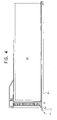
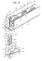
- Figures 2 through 9 are various views of the product separation and selection tray system according to the present invention.
- the system 50 includes a base 54 and two opposed L-shaped side walls 56 and 58.
- the side walls 56 and 58 are slidably mounted on the base 54 so as to be able to be varied in lateral separation distance from each other and from central fixed dividing wall 60 to accommodate various sized products to be dispensed.
- An indicia display holder 62 (made of component parts 62a and 62b, as shown in Figure 6 ) is located on a leading edge of base 54 to identify a product's name, a price of the product and/or to identify indicia to be entered into keypad 40 to select a particular product.
- Actuating lever 64 controls operation of a rotator 66 and a gate 68 for dispensing of product from a space 70 defined between side wall 56 and central wall 60 or a space 72 defined between central wall 60 and end wall 58.
- product is moved toward the leading edge of the system 50 by the use of feet 74 having a projection 76 which is slidable in a track 78 of the central wall 60 for placement of the feet relative to the forward end of the base 54.
- the track may be positioned in the base.
- the product separation and selection tray system of the present invention includes rotator 66 having flat side surfaces 66a and 66b intersecting at one end and terminating at an opposite end in curved surfaces 66c. At the intersection of flat surfaces 66a, 66b, is located an extended pin 86 having head 88 engaged in recess 90 at a leading edge 92 of central wall 60. The opposite end 90 of pin 86 is engaged in a bushing 92 mounted on the upper surface of base 54.
- the pin 86 fixed in the rotator 66 allows pivotal movement of the rotator during movement of the tab portion 94 of the lever 64.
- a pin 96 extends through arcuate slot 102 in the base 54 and through a slot 98 in the lever 64 to engage at its bottom end in bushing 100. Pin 96 then passes into arcuate slot 104 of retaining plate 106.
- Retaining plate 106 is secured to the underside of the base 54 as shown in Figure 5 .
- the upper end of pin 96 is secured within rotator 66 at a point midway between sides 66a and 66b along a radial line projecting from pin 86 in the direction of curved side 66c.
- the lever 64 is pivoted around boss 110 by the anchoring of circular opening 108 of the lever 64 in the boss 110 projecting upwardly from the retaining plate 106.
- the rotators 66 shown on shelves 52a, 52c, 52d and 52e in Figure 1 illustrate the normal, at rest positioning of the rotators 66.
- the tab 94 is contacted and moved to the right as shown in the system 50 on shelf 52b, the rotator 66 is pivoted such that side 66a is in line, parallel with central wall 60. Then rotator 66 allows product 112 to be advanced past rotator 66 under the bias force of spring 80.
- Gate 68 is mounted at one end on an elongated pin 114 having pin head 116 mounted in a recess 118 in central wall 60.
- the bottom end 120 of the pin 114 is mounted in a circular recess 122 defined in a partition 124 separating the rotator 66 from the gate 68.
- a pin 126 extends through a circular opening 128 in the lever 64 and then passes through arcuate slot 129 in base 54 and arcuate slot 130 in the retaining plate 106. The opposite end of pin 126 is secured in a recess in a trailing edge 132 of gate 68.
- a rear terminal flange 134 of the lever 64 is slidable in arcuate slot 136 in retaining plate 106.
- lever 64 pivots about pivot boss 110 and the retaining flange 134 at the opposite end of the lever 64 moves in the opposite direction to the tab 94.
- This action causes side 66a of rotator 66 to move to a position parallel to central wall 60.
- Gate 68 will simultaneously move its rear edge 132 in a direction perpendicular to central wall 60 in channel 70 so as to prevent advancement of a second, successive product in channel 70 against the bias force of spring 80.
- new product may be pushed in from the front. Also, it is possible to remove the tray "on site” and add new product from the rear of the tray.
- an engaging mechanism 140 as shown on the underside of the base 54 in Figure 5 can be used to engage with complementary shaped openings in a rear portion of shelves 52a through 52e. Therefore, as long as the total width of each shelf is known, the modular feature of the tray system 50 may be used to design mounting of an appropriate number of tray systems 50 on each shelf.
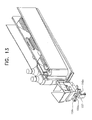
- FIGs 10 through 14 the progression of release of product 112 into an elevator cup 150 of a product acquisition and transport system is illustrated.
- the X-Y axis product acquisition and transport system is driven, based upon keypad actuation of a desired choice of product to raise the elevator cup in the Y-direction with selection channel 95 surrounding tab 94 of lever 64.
- the tab 94 of lever 64 is engaged by a sidewall 152 of channel 95, upon sideways movement of the cup 150, the rotator 66 moves out of the way of the product 112 and the gate 68 engages the next successive bottle 154.
- the forward movement of the bottle 154 is actuated by the slider 84, as biased by spring 80, until the bottle 154 engages the gate 68 as shown in Figure 11 .
- foot 74 is biased by a flat wound spring. This could be the primary force on the bottles.
- Spring 80 and slider 84 could be used to move the last bottle past the gate and rotator.
- the release of the tab 94 by reverse lateral movement of the cup 150 to the position shown in Figure 12 releases the gate from engaging the bottle 154 and allows forward movement of the bottle 154 until engaging the rotator 66.
- a sensor confirms placement of product in the elevator cup 150.
- vertically extending flange 151 extends across the path of product in the cup 150.
- the flange 151 is pivoted about pin 153 when product is pushed into the cup 150.
- Pivotable flange 155 stabilizes the bottle in the cup.
- a switch 153 is not actuated by flange 151 thereby indicating presence of a bottle.
- Figures 13 and 14 show details of the flange 157 for use in guiding movement of the cup 150 with respect to horizontal movement by connection to a tension element such as a horizontal toothed belt. Also guide wheels 159a, 159b, 159c assist in traversing along a horizontal guide rail as the guide rail is raised vertically for positioning of the cup in front of a tray system 50.
- Figure 16 schematically illustrates the product acquisition and transport system 160 for movement of the cup 150 to any position in front of a product to be dispensed as well as for movement of the cup to deliver the product to a discharge port.
- Cup 150 is secured to tension element 162 which may be a belt, chain or cable for movement of the cup by rotation of a fixed motor 164.
- the motor is connected by a drive shaft 166 to a drive roller 168.
- Actuation of the motor causes the tension element 162 to run across driven rollers 170, 172, 174 and 176.
- the rollers 170, 172, 174 are mounted on a horizontal rail 178. When the rail 178 is fixed in position, movement of the tension element 162 causes the cup 150 to traverse the rail so as to be located in front of a particular separation and selection tray system 50.
- Movement of the cup vertically is accomplished by a tension element 180 driven by a fixed motor 182 having drive shaft 184 and drive roller 186.
- the tension element 180 is fixed to the rail 178 so upon actuation of the motor 182, the tension element 180 rotates around driven roller 188 for vertical movement of the rail and thereby also the cup 150.
- FIGS 17 through 19 various views are shown of the positioning of the cup adjacent to a delivery door (not shown).
- the product is shown in dotted lines, since for illustrative purposes, the elevated position of flange 151 indicates that product should not be present in the cup 150.
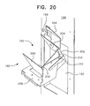
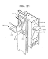
- the discharge mechanism 150 For delivery of product from the cup, the discharge mechanism 150 as shown in Figures 20 and 21 is used.
- the product is delivered through a discharge window 192 by engagement of an upper wall portion 194 of the cup 150 with a projecting tab 196 fixed on a sidewall 198 of the discharge port.
- a projecting tab 196 Fixed on a sidewall 198 of the discharge port.
- Continued downward movement of the cup causes three interconnected sidewalls 200, 202, 204 of the cup to pivot around pivot point 206.
- the sidewalls 200, 202 and 204 engaging a product tilt the product until the bottom of the product clears the bottom wall 208 of the cup to allow the product to slide at an angle of approximately 45 degrees into open delivery window 192.
- Smooth movement of the sidewalls 200, 202 and 204 is ensured by a cam slot 210 of wall 202 passing along a fixed screw or a bolt, pin or rivet 212.
- release of product through the window 192 is allowed by the vertical movement of the cup 150 to engage a sliding delivery door 214 which normally covers the window 192 of a delivery box.
- the door 214 is moved by engagement of an edge of bottom 208 of the cup with a tab 216 of the door.
- the product is thereby released into a delivery box 218 which is allowed to tilt forward by gravity or by engagement with a finger of the consumer in a finger hole or finger recess 220.
- the delivery box 218 is tilted so that the product 112 may be grabbed by its cap 222 and removed from the machine.
- a mechanism prevents the delivery box 218 from tilting out of the machine until after the door 214 is moved to the retracted position shown in Figure 21 and the product is dropped into the basket. Not until upward movement of the cup and release of the sliding door, so that the door may cover the delivery window 192, will the basket be allowed to be pivoted towards the consumer for access to the product.
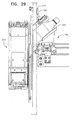
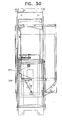
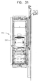
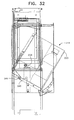
- Figures 22 through 32 illustrate the delivery of product from the elevator cup 150 through the delivery window 192 after opening of the delivery door 214 and passage of the product into the delivery box 218.
- the product 250 approaches the delivery door 214 by rollers 159a, 159b and 159c resting upon edge 252 of horizontal rail 254.
- Horizontal rail 254 is moved vertically as was explained with reference to Figure 16 .
- Driven rollers 256a, 256b are engaged by a tension element such as a driven chain (not shown), for example, so as to move the elevator cup 150 along the horizontal rail 254.
- a port latch 258 located adjacent to an uppermost edge 260 of the delivery door 214 is engaged by a horizontally extending flange 262 located underneath the elevator cup 150.
- the upper wall portion 194 engages the projecting tab 196 as was explained with reference to Figure 20 and as shown in Figure 23 .
- the delivery door 214 is lowered vertically to open window 192 so that the bottle 250 may be tilted, and by gravity, fed through the delivery window 192.
- the downward movement of the port latch 258 causes engagement with a weld pin to lock the delivery box in position and prevent the delivery box from being opened. This is a safety feature so that the customer's hand is not inside the delivery box as the product is being dispensed.
- the bias force on the delivery door 214 is caused by anchoring a spring at one end on projection 264 whereas the other end of the spring (not shown) is secured to a projection 266 located at the bottom of the delivery door 214.
- the door 214 slides in guide track 268 to ensure smooth movement.
- an optic sensor emitter board 270 projects light beam 272 through holes 274, 276 so that the line of sight with optic sensor detector board 278 is clear.
- a signal is produced indicating that the delivery box is in position to receive a product.
- Counterweights 280, 282 maintain the position of the delivery box in a closed position until a product is ready to be delivered and the delivery box is pivoted about pivot point 284.
- the area encircled in Figure 25 illustrates the port latch 258 in a rest position prior to the dispensing of product through the delivery door 214.
- the delivery box 218 is movable. Movement is allowed because the port latch 258 has not yet engaged weld pin 286 in groove 288 of the port latch.
- a sensor switch 290 indicates engagement with the exterior wall 292 of the vending machine.
- the downward movement of the elevator cup first opens the port latch and then contacts the delivery door as shown in Figure 28 .
- the elevator cup 150 has completely opened the delivery door.
- the product 250 is delivered to the delivery box 214.
- the delivery box is maintained in position by engagement of the port latch with the weld pin 286 as shown in Figure 30 . This prevents the delivery box from being opened.
- the bottle 250 is located within the delivery box 214 so that, as shown in Figure 32 , after upward movement of the door 214, the weld pin 286 is released from the port latch 258 and is allowed to travel along arcuate guide groove 290 for controlling the pivotal movement of the delivery box.
- the weight of the product being vended rotates the delivery box forward to present the product to the customer.
Landscapes
- Physics & Mathematics (AREA)
- General Physics & Mathematics (AREA)
- Vending Machines For Individual Products (AREA)
- Control Of Vending Devices And Auxiliary Devices For Vending Devices (AREA)
- Beverage Vending Machines With Cups, And Gas Or Electricity Vending Machines (AREA)
Applications Claiming Priority (2)
| Application Number | Priority Date | Filing Date | Title |
|---|---|---|---|
| US10/670,776 US7222748B2 (en) | 2003-09-26 | 2003-09-26 | Clear door vending machine |
| EP04754370A EP1665178A4 (fr) | 2003-09-26 | 2004-06-03 | Distributeur a porte vitree |
Related Parent Applications (2)
| Application Number | Title | Priority Date | Filing Date |
|---|---|---|---|
| EP04754370.7 Division | 2004-06-03 | ||
| EP04754370A Division EP1665178A4 (fr) | 2003-09-26 | 2004-06-03 | Distributeur a porte vitree |
Publications (2)
| Publication Number | Publication Date |
|---|---|
| EP2138982A2 true EP2138982A2 (fr) | 2009-12-30 |
| EP2138982A3 EP2138982A3 (fr) | 2010-02-24 |
Family
ID=34376002
Family Applications (3)
| Application Number | Title | Priority Date | Filing Date |
|---|---|---|---|
| EP04754370A Withdrawn EP1665178A4 (fr) | 2003-09-26 | 2004-06-03 | Distributeur a porte vitree |
| EP09012293A Expired - Lifetime EP2141668B1 (fr) | 2003-09-26 | 2004-06-03 | Système de distribution des produits pour un distributeur automatique |
| EP09012292A Withdrawn EP2138982A3 (fr) | 2003-09-26 | 2004-06-03 | Système de sélection et séparation des produits dans un distributeur automatique |
Family Applications Before (2)
| Application Number | Title | Priority Date | Filing Date |
|---|---|---|---|
| EP04754370A Withdrawn EP1665178A4 (fr) | 2003-09-26 | 2004-06-03 | Distributeur a porte vitree |
| EP09012293A Expired - Lifetime EP2141668B1 (fr) | 2003-09-26 | 2004-06-03 | Système de distribution des produits pour un distributeur automatique |
Country Status (13)
| Country | Link |
|---|---|
| US (4) | US7222748B2 (fr) |
| EP (3) | EP1665178A4 (fr) |
| AT (1) | ATE531012T1 (fr) |
| AU (3) | AU2004280866B2 (fr) |
| CA (2) | CA2666089C (fr) |
| CY (1) | CY1112360T1 (fr) |
| DK (1) | DK2141668T3 (fr) |
| ES (1) | ES2375895T3 (fr) |
| MX (1) | MXPA06002768A (fr) |
| PL (1) | PL2141668T3 (fr) |
| PT (1) | PT2141668E (fr) |
| SI (1) | SI2141668T1 (fr) |
| WO (1) | WO2005036482A2 (fr) |
Families Citing this family (73)
| Publication number | Priority date | Publication date | Assignee | Title |
|---|---|---|---|---|
| US8195328B2 (en) | 2003-09-19 | 2012-06-05 | Vesta Medical, Llc | Combination disposal and dispensing apparatus and method |
| US7222748B2 (en) * | 2003-09-26 | 2007-05-29 | Royal Vendors, Inc. | Clear door vending machine |
| US7837059B2 (en) * | 2004-02-27 | 2010-11-23 | Sanden Vendo America, Inc. | Product acquisition devices and methods for vending machines |
| EP1763851A4 (fr) * | 2004-02-27 | 2011-11-30 | Sandenvendo America Inc | Distributeur automatique et pieces constitutives de ce dernier |
| US8162174B2 (en) * | 2004-02-27 | 2012-04-24 | Sandenvendo America, Inc. | Retrieval systems for vending machines |
| US20070138199A1 (en) * | 2004-03-09 | 2007-06-21 | Jae-Jeong Yang | Feed mechanism for a vending machine |
| US20120116577A1 (en) * | 2004-05-19 | 2012-05-10 | Frank Ottomanelli | Automated food service system for remote recreational facilities |
| JP4551396B2 (ja) * | 2004-05-19 | 2010-09-29 | 株式会社湯山製作所 | 薬品払出装置 |
| JP4601386B2 (ja) * | 2004-10-15 | 2010-12-22 | 株式会社湯山製作所 | 薬剤カート |
| US20060199648A1 (en) * | 2005-03-07 | 2006-09-07 | Mitchell Michael J | Gaming machine having convenience platform |
| WO2006112075A1 (fr) * | 2005-04-08 | 2006-10-26 | Tosho Inc. | Cassette de medicaments, dispositif et systeme d'administration de medicaments |
| US7431176B2 (en) * | 2005-06-17 | 2008-10-07 | Barryco Technologies Inc. | Dispensing machine to store and dispense elongated containers vertically |
| CA2616127A1 (fr) * | 2005-07-20 | 2007-01-25 | Coin Acceptors, Inc. | Procede de modernisation d'un distributeur automatique |
| US20070017928A1 (en) * | 2005-07-20 | 2007-01-25 | Coppola Richard G | Method of retrofitting a vending machine |
| JP2007094684A (ja) * | 2005-09-28 | 2007-04-12 | Sanden Corp | 自動販売機 |
| US7837058B2 (en) * | 2005-10-14 | 2010-11-23 | Crane Merchandising Systems, Inc. | Product transport system for a vending machine |
| US7802700B2 (en) * | 2005-10-14 | 2010-09-28 | Crane Merchandising Systems, Inc. | Product discharge and delivery system for a vending machine |
| US8989893B2 (en) * | 2006-01-31 | 2015-03-24 | Robofusion, Inc. | Method and apparatus for dispensing frozen confectionery |
| CA2640461A1 (fr) * | 2006-01-31 | 2007-08-09 | Puffin Innovations, Llc | Procede et appareil de distribution de friandise glacee |
| WO2008045472A2 (fr) * | 2006-10-10 | 2008-04-17 | Dixie-Narco, Inc. | Système de distribution et de déchargement de produit pour un distributeur automatique |
| US8534494B2 (en) * | 2006-10-26 | 2013-09-17 | Crane Merchandising Systems, Inc. | Product detection system for a vending machine |
| USD647926S1 (en) | 2007-01-31 | 2011-11-01 | Robofusion, Inc. | Kiosk and machine for assembly of frozen confectionery |
| USD643861S1 (en) | 2007-01-31 | 2011-08-23 | Puffin Innovations, Llc | Kiosk and machine for assembly of frozen confectionery |
| EP2012281B1 (fr) * | 2007-05-21 | 2014-11-19 | Sanden Corporation | Dispositif de réalisation de marchandises |
| JP5013972B2 (ja) * | 2007-05-31 | 2012-08-29 | サンデン株式会社 | 自動販売機の商品コラム |
| CN104072561B (zh) * | 2007-06-19 | 2017-12-22 | 路易斯安那州州立大学及农业机械学院管理委员会 | 信使rna帽的抗‑反向硫代磷酸类似物的合成和用途 |
| US20090084812A1 (en) * | 2007-09-28 | 2009-04-02 | The Coca-Cola Company | Package Advancement System |
| US20090101614A1 (en) * | 2007-10-22 | 2009-04-23 | The Coca-Cola Company | Unpowered End Effector for Dispensing Apparatus |
| US8038018B1 (en) * | 2008-03-25 | 2011-10-18 | Vendmore Systems, Llc | Vending machine product stabilizer |
| US8205770B2 (en) * | 2008-08-21 | 2012-06-26 | Crane Merchandising Systems, Inc. | Vending machine user interface guide; electronic coin return; and hinged delivery bin |
| US8556119B2 (en) * | 2009-03-24 | 2013-10-15 | Crane Merchandising Systems, Inc. | Horizontal product discharge system for a vending machine |
| US20100253185A1 (en) * | 2009-04-03 | 2010-10-07 | Seaga Manufacturing, Inc. | Addressable Information Display |
| EP2363841A1 (fr) * | 2010-03-04 | 2011-09-07 | Automated Retail Concepts B.V. | Distributeur de produits et procédé de distribution |
| NL2004342C2 (en) * | 2010-03-04 | 2011-09-06 | Automated Retail Concepts B V | Product dispensing machine and dispensing method. |
| CN103119633B (zh) * | 2010-06-25 | 2015-06-17 | 富士电机株式会社 | 自动售货机 |
| EP2587459B1 (fr) * | 2010-06-25 | 2017-07-26 | Fuji Electric Co., Ltd. | Dispositif de rangement de produits pour distributeur automatique |
| IT1404085B1 (it) * | 2010-12-22 | 2013-11-08 | Magex S R L | Dispositivo di erogazione perfezionato per distributori automatici di prodotti |
| US9640014B2 (en) | 2011-01-04 | 2017-05-02 | Fawn Engineering Corporation | Vending machine with elevator delivery of vended product to customer access |
| ES2388259B1 (es) * | 2011-03-15 | 2013-08-19 | Gallardo Y Martín Ingeniería, S.L. | Vitrina suministradora de envases de bebidas. |
| ES2400570B1 (es) * | 2011-04-26 | 2014-06-30 | Jofemar, S.A. | Maquina expendedora automatica |
| MX344332B (es) | 2011-05-04 | 2016-12-13 | Kiosk Information Systems Inc | Sistemas y metodos para la exhibicion de mercancia, la venta y el control de inventario. |
| DE102011082371A1 (de) * | 2011-09-08 | 2013-03-14 | Sielaff Gmbh & Co. Kg Automatenbau | Warenausgabevorrichtung, Verkaufsautomat sowie Verfahren |
| ITMI20120763A1 (it) * | 2012-05-07 | 2013-11-08 | Fas International Spa | Distributore automatico. |
| US10083430B2 (en) | 2012-06-08 | 2018-09-25 | Ronny Hay | Computer-controlled, unattended, automated checkout store outlet system and related method |
| US9536236B2 (en) | 2012-06-08 | 2017-01-03 | Ronny Hay | Computer-controlled, unattended, automated checkout store outlet and related method |
| US9317989B2 (en) * | 2012-10-02 | 2016-04-19 | Kiosk Information Systems, Inc. | Camera audit accepter mechanism and camera audit dispensing mechanism |
| KR101620251B1 (ko) * | 2013-08-09 | 2016-05-12 | 후지 덴키 가부시키가이샤 | 상품 수납 장치 |
| AU2014369976B2 (en) * | 2013-12-23 | 2019-07-11 | The Coca-Cola Company | Merchandiser with product dispensing chute mechanism |
| US9870671B1 (en) | 2014-04-07 | 2018-01-16 | Fawn Engineering Corporation | Mechanical lift for delivery bins in vending machines |
| JP2017521780A (ja) * | 2014-07-01 | 2017-08-03 | ロニー ヘイ | コンピュータ制御式の無人自動チェックアウト式店舗アウトレット及び関連方法 |
| ES2581252B1 (es) * | 2015-03-02 | 2017-05-25 | Jofemar, S.A. | Máquina expendedora automática |
| DE102015212271B3 (de) * | 2015-07-01 | 2016-06-09 | Sielaff Gmbh & Co. Kg Automatenbau | Liftvorrichtung, Warenautomat |
| US10055928B1 (en) * | 2016-04-11 | 2018-08-21 | Fawn Engineering Corporation | Highly adjustable push-type dispensing module for dispensing items |
| CN106364830B (zh) * | 2016-08-23 | 2018-10-16 | 浙江锦源实业有限公司 | 电力营业厅手机存放装置 |
| EP3861891B1 (fr) * | 2016-12-12 | 2024-01-31 | SMARK GmbH | Système de stockage et de préhension |
| US10490014B2 (en) * | 2016-12-16 | 2019-11-26 | Pepsico, Inc. | Lean vending machine |
| EP3568841B1 (fr) * | 2017-01-12 | 2024-10-09 | Crane Payment Innovations, Inc. | Système de distribution de produit de type distributeur automatique amélioré |
| USD861073S1 (en) * | 2017-04-03 | 2019-09-24 | Pepsico, Inc. | Vending machine |
| CN110634234B (zh) * | 2018-06-25 | 2020-11-20 | 威海新北洋数码科技有限公司 | 一种自动售货机及其出货方法 |
| CN109255885B (zh) * | 2018-08-17 | 2020-10-30 | 河南智售宝智能科技有限公司 | 售货机控制方法及单次多件出货控制方法 |
| US10846972B2 (en) | 2018-08-31 | 2020-11-24 | Royal Vendors, Inc. | Vending machine |
| US10867463B2 (en) * | 2018-09-18 | 2020-12-15 | Pepsico, Inc. | Vending machine |
| IT201800009313A1 (it) * | 2018-10-10 | 2020-04-10 | Fas Int Spa | Dispositivo per lo stoccaggio e l’erogazione di prodotti. |
| RU192747U1 (ru) * | 2018-12-13 | 2019-09-30 | Виталий Владимирович Бакалейко | Устройство выдачи товара в торговом автомате |
| CN110942554B (zh) * | 2019-11-26 | 2021-10-12 | 江苏蓝天空港设备有限公司 | 自动售货设备 |
| CN111354129B (zh) * | 2020-04-10 | 2025-05-02 | 深圳市创和嘉信息技术有限公司 | 一种具有高容积率的售货机 |
| CN111508144B (zh) * | 2020-04-24 | 2022-02-18 | 广州磐众智能科技有限公司 | 一种调节货道宽度的自动扫描重设方法 |
| WO2021222627A1 (fr) * | 2020-04-30 | 2021-11-04 | Crane Merchandising Systems, Inc. | Système de distribution des produits de distributeur automatique à vitesse de récupération variable |
| CN111627156B (zh) * | 2020-06-11 | 2021-10-29 | 张勇 | 一种酒店用无人售卖机 |
| US20220058908A1 (en) | 2020-08-19 | 2022-02-24 | Pepsico, Inc. | Product delivery mechanism for a vending machine |
| CN113057451B (zh) * | 2021-03-08 | 2022-06-10 | 焦作大学 | 一种企业档案储存用的智能化档案柜 |
| US11620868B2 (en) | 2021-07-22 | 2023-04-04 | Trinity Axis Inc. | Techniques to dispense an item and release a jammed item from a dispensing system |
| US20250014431A1 (en) * | 2023-04-11 | 2025-01-09 | Gary Balaban | Method for game play of an arcade game machine where a user tries to stop an LED light on or at a specific location in time |
Citations (1)
| Publication number | Priority date | Publication date | Assignee | Title |
|---|---|---|---|---|
| WO1999019849A1 (fr) | 1997-10-14 | 1999-04-22 | Gross-Given Manufacturing Company | Appareil et procede de distribution d'articles |
Family Cites Families (52)
| Publication number | Priority date | Publication date | Assignee | Title |
|---|---|---|---|---|
| US3165231A (en) * | 1958-03-10 | 1965-01-12 | Ferro Stamping Co | Vending machine |
| US3348732A (en) * | 1966-09-02 | 1967-10-24 | Schwarz Heinz Walter | Article dispensing device |
| US3837528A (en) * | 1970-07-06 | 1974-09-24 | Kinematics & Controls Corp | Article delivery systems for vending machines having sequentially actuated dispensers |
| BE792391A (fr) * | 1971-12-08 | 1973-06-07 | Millies Clarence F | Dispositif destine a adapter un distributeur automatique a des objets de dimensions differentes |
| CA1039245A (fr) * | 1975-05-14 | 1978-09-26 | Leonard P. Falk | Distributeur a dispositif elevateur |
| US4252250A (en) * | 1978-09-28 | 1981-02-24 | Umc Industries, Inc. | Multiple-beam optical sensing system for an article vendor |
| US4483459A (en) * | 1981-07-24 | 1984-11-20 | Mars Limited | Dispensing machine |
| US4560088A (en) * | 1984-05-11 | 1985-12-24 | Tan Larry K | Vending machine with dispensing operating system movable in X-Y coordinate axes |
| SE459618B (sv) * | 1984-11-19 | 1989-07-17 | Bo Friberg | Varuautomat foer vaermning och utlaemning av faerdiglagade matportioner |
| US4812629A (en) * | 1985-03-06 | 1989-03-14 | Term-Tronics, Incorporated | Method and apparatus for vending |
| JPH0237080Y2 (fr) * | 1985-09-12 | 1990-10-08 | ||
| US4687119A (en) * | 1985-10-23 | 1987-08-18 | Hubert Juillet | Dispenser for hot and cold products |
| DE3608942A1 (de) * | 1986-03-18 | 1987-09-24 | Sielaff Gmbh Co Automaten | Ausgabeeinrichtung an warenschaechten eines selbstverkaeufers |
| JPH0348694Y2 (fr) * | 1988-03-16 | 1991-10-17 | ||
| DE3816028A1 (de) * | 1988-05-10 | 1989-11-23 | Dany S Snack Gmbh & Co | Ausgabe-automat fuer aufgebackene portionierte nahrungsmittel |
| USRE35743E (en) * | 1988-09-12 | 1998-03-17 | Pearson Ventures, L.L.C. | Patient medication dispensing and associated record keeping system |
| US5105978A (en) * | 1990-01-16 | 1992-04-21 | Hobart Corporation | Apparatus for storing and dispensing frozen comestibles |
| US5121854A (en) * | 1990-01-16 | 1992-06-16 | Hobart Corporation | Apparatus for storing and dispensing frozen comestibles |
| NL9001804A (nl) * | 1990-08-10 | 1992-03-02 | Veroost Bedrijfsontwikkeling B | Inrichting voor het in een winkel voor verkoop gekoeld opslaan van aan bederf onderhevige voedingsmiddelen. |
| US5570811A (en) * | 1994-11-01 | 1996-11-05 | Fawn Engineering Corporation | Apparatus and method for dispensing items from a vending machine |
| US5611248A (en) * | 1995-06-02 | 1997-03-18 | Ats Automation Tooling Systems Inc. | Two-axis robot |
| FR2740682B1 (fr) * | 1995-11-06 | 1997-12-05 | Oreal | Composition topique contenant de la capsazepine |
| JP3673336B2 (ja) * | 1996-09-06 | 2005-07-20 | サンデン株式会社 | 自動販売機 |
| JP3860628B2 (ja) * | 1996-09-19 | 2006-12-20 | サンデン株式会社 | 自動販売機の商品搬出装置 |
| US5881911A (en) * | 1996-10-09 | 1999-03-16 | The Coca-Cola Company | Vending machine |
| JPH10241030A (ja) * | 1997-02-25 | 1998-09-11 | Sanden Corp | 自動販売機 |
| EP0996935B1 (fr) * | 1997-04-23 | 2004-09-15 | Jürgen Walter | Distributeur automatique d'argent |
| BE1011225A3 (nl) * | 1997-06-19 | 1999-06-01 | New Distribution Systems Kort | Verdeelinstallatie voor stukgoederen. |
| US20010000610A1 (en) * | 1997-07-29 | 2001-05-03 | Johnson David K. | Apparatus and method for dispensing items from a vending machine |
| US6564964B2 (en) * | 1997-07-29 | 2003-05-20 | David K. Johnson | Apparatus for dispensing items from a vending machine |
| US6149031A (en) * | 1997-08-26 | 2000-11-21 | Nature-Pac Inc. | Beverage dispensing machine and method of operation thereof |
| US6352174B1 (en) * | 1997-08-26 | 2002-03-05 | Nature-Pac Inc. | Carton dispensing machine |
| US6513677B1 (en) * | 1997-10-14 | 2003-02-04 | Gross-Given Manufacturing Company | Apparatus and method for vending products |
| DE19834155C2 (de) * | 1998-01-05 | 2000-01-20 | Gerhard Zettler | Getränkeautomat |
| DE19806029C1 (de) * | 1998-02-13 | 1999-09-02 | Siemens Nixdorf Inf Syst | Vorrichtung zur Entnahme von Banknotenbündeln und Bereitstellung an einer Entnahmestelle |
| JP3743153B2 (ja) * | 1998-02-26 | 2006-02-08 | 富士電機リテイルシステムズ株式会社 | 自動販売機の商品収納払出装置 |
| US6199720B1 (en) * | 1998-03-20 | 2001-03-13 | The Coca-Cola Company | Vending machine |
| US6241121B1 (en) * | 1998-03-31 | 2001-06-05 | Sanyo Electric Co., Ltd | Commodity accommodating unit of an automatic vending machine |
| ES2150385B1 (es) * | 1998-04-23 | 2001-06-16 | Inversiones Taconera S L | Perfeccionamientos en la patente p 9800864 por: maquina expendedora. |
| US6112943A (en) * | 1998-07-24 | 2000-09-05 | Vendcraft Inc | Vending machine for bottles and method of vending bottles |
| US6464104B1 (en) * | 1998-10-08 | 2002-10-15 | Gregory Waddell | Vending system |
| US6283324B1 (en) * | 1999-01-08 | 2001-09-04 | Stuart M. Jenkins | Coin roll dispensing apparatus |
| ES2160032B1 (es) * | 1999-02-12 | 2003-02-16 | Azkoyen Ind Sa | Mecanismo extractor para maquinas de venta automatica. |
| US6286715B1 (en) * | 1999-04-01 | 2001-09-11 | The Coca-Cola Company | Transparent front vending machine |
| US6247610B1 (en) * | 1999-04-01 | 2001-06-19 | The Coca-Cola Company | Transparent front vending machine |
| US6682289B1 (en) * | 1999-04-02 | 2004-01-27 | The Coca-Cola Company | Dispensing apparatus and method of using same |
| US20030034354A1 (en) * | 1999-08-07 | 2003-02-20 | Munroe Chirnomas | Article retrieving mechanism |
| US6755322B1 (en) * | 2000-02-22 | 2004-06-29 | Hettie J. Herzog | Automated shopping system and apparatus |
| EP1162582A3 (fr) * | 2000-06-05 | 2003-03-12 | Sanden Corporation | Distributeur automatique |
| US6224455B1 (en) * | 2000-08-03 | 2001-05-01 | Mattel, Inc. | Toy figure simulating musical instrument play |
| US6868983B2 (en) * | 2001-05-23 | 2005-03-22 | Munroe Chirnomas | Method and apparatus for positioning an article handling device |
| US7222748B2 (en) * | 2003-09-26 | 2007-05-29 | Royal Vendors, Inc. | Clear door vending machine |
-
2003
- 2003-09-26 US US10/670,776 patent/US7222748B2/en not_active Expired - Lifetime
-
2004
- 2004-06-03 EP EP04754370A patent/EP1665178A4/fr not_active Withdrawn
- 2004-06-03 SI SI200431782T patent/SI2141668T1/sl unknown
- 2004-06-03 WO PCT/US2004/017750 patent/WO2005036482A2/fr not_active Ceased
- 2004-06-03 PT PT09012293T patent/PT2141668E/pt unknown
- 2004-06-03 ES ES09012293T patent/ES2375895T3/es not_active Expired - Lifetime
- 2004-06-03 AU AU2004280866A patent/AU2004280866B2/en not_active Ceased
- 2004-06-03 PL PL09012293T patent/PL2141668T3/pl unknown
- 2004-06-03 DK DK09012293.8T patent/DK2141668T3/da active
- 2004-06-03 AT AT09012293T patent/ATE531012T1/de active
- 2004-06-03 EP EP09012293A patent/EP2141668B1/fr not_active Expired - Lifetime
- 2004-06-03 MX MXPA06002768A patent/MXPA06002768A/es active IP Right Grant
- 2004-06-03 CA CA2666089A patent/CA2666089C/fr not_active Expired - Fee Related
- 2004-06-03 CA CA2540277A patent/CA2540277C/fr not_active Expired - Fee Related
- 2004-06-03 EP EP09012292A patent/EP2138982A3/fr not_active Withdrawn
- 2004-10-20 US US10/968,089 patent/US7055716B2/en not_active Expired - Lifetime
-
2006
- 2006-03-31 US US11/394,323 patent/US7128237B2/en not_active Expired - Fee Related
- 2006-03-31 US US11/394,124 patent/US7222749B2/en not_active Expired - Lifetime
-
2009
- 2009-08-14 AU AU2009208170A patent/AU2009208170B2/en not_active Ceased
- 2009-08-14 AU AU2009208171A patent/AU2009208171B2/en not_active Ceased
-
2012
- 2012-01-24 CY CY20121100079T patent/CY1112360T1/el unknown
Patent Citations (1)
| Publication number | Priority date | Publication date | Assignee | Title |
|---|---|---|---|---|
| WO1999019849A1 (fr) | 1997-10-14 | 1999-04-22 | Gross-Given Manufacturing Company | Appareil et procede de distribution d'articles |
Also Published As
Similar Documents
| Publication | Publication Date | Title |
|---|---|---|
| CA2666089C (fr) | Distributeur a porte vitree | |
| US6412654B1 (en) | Vending machine | |
| US7802700B2 (en) | Product discharge and delivery system for a vending machine | |
| EP3568841B1 (fr) | Système de distribution de produit de type distributeur automatique amélioré | |
| US6868985B2 (en) | Small-sized vending machine | |
| JP5630079B2 (ja) | カップ式自動販売機のカップ搬送装置 | |
| US6422417B1 (en) | Cigarette vending machine and vending machine dispenser | |
| JP2008262488A (ja) | 自動販売機 | |
| JP2005032093A (ja) | 自動販売機 | |
| AU748563B2 (en) | Vending machine | |
| JP2003109086A (ja) | 自動販売機の商品搬出装置 | |
| JP2003272040A (ja) | 自動販売機 | |
| JP2002074492A (ja) | 自動販売機の商品払出装置 | |
| JP2007172355A (ja) | 自動販売機の商品搬送装置 | |
| KR19980024722U (ko) | 자동판매기용 제품 인출장치 | |
| JP2003157470A (ja) | 自動販売機の商品搬出装置 | |
| JPH02299091A (ja) | 自動販売機の硬貨返却装置 |
Legal Events
| Date | Code | Title | Description |
|---|---|---|---|
| PUAI | Public reference made under article 153(3) epc to a published international application that has entered the european phase |
Free format text: ORIGINAL CODE: 0009012 |
|
| AC | Divisional application: reference to earlier application |
Ref document number: 1665178 Country of ref document: EP Kind code of ref document: P |
|
| AK | Designated contracting states |
Kind code of ref document: A2 Designated state(s): AT BE BG CH CY CZ DE DK EE ES FI FR GB GR HU IE IT LI LU MC NL PL PT RO SE SI SK TR |
|
| PUAL | Search report despatched |
Free format text: ORIGINAL CODE: 0009013 |
|
| AK | Designated contracting states |
Kind code of ref document: A3 Designated state(s): AT BE BG CH CY CZ DE DK EE ES FI FR GB GR HU IE IT LI LU MC NL PL PT RO SE SI SK TR |
|
| 17P | Request for examination filed |
Effective date: 20100525 |
|
| 17Q | First examination report despatched |
Effective date: 20120404 |
|
| RIC1 | Information provided on ipc code assigned before grant |
Ipc: G07F 11/60 20060101ALI20130521BHEP Ipc: G07F 11/16 20060101AFI20130521BHEP Ipc: G07F 11/42 20060101ALI20130521BHEP |
|
| GRAP | Despatch of communication of intention to grant a patent |
Free format text: ORIGINAL CODE: EPIDOSNIGR1 |
|
| RIN1 | Information on inventor provided before grant (corrected) |
Inventor name: HALTERMAN, BRIAN Inventor name: RING, MIKE Inventor name: HOLDWAY, JOHN |
|
| INTG | Intention to grant announced |
Effective date: 20130827 |
|
| GRAS | Grant fee paid |
Free format text: ORIGINAL CODE: EPIDOSNIGR3 |
|
| GRAP | Despatch of communication of intention to grant a patent |
Free format text: ORIGINAL CODE: EPIDOSNIGR1 |
|
| STAA | Information on the status of an ep patent application or granted ep patent |
Free format text: STATUS: GRANT OF PATENT IS INTENDED |
|
| INTG | Intention to grant announced |
Effective date: 20140224 |
|
| STAA | Information on the status of an ep patent application or granted ep patent |
Free format text: STATUS: THE APPLICATION IS DEEMED TO BE WITHDRAWN |
|
| 18D | Application deemed to be withdrawn |
Effective date: 20140708 |