EP2139091A1 - Piece de champ - Google Patents
Piece de champ Download PDFInfo
- Publication number
- EP2139091A1 EP2139091A1 EP08740046A EP08740046A EP2139091A1 EP 2139091 A1 EP2139091 A1 EP 2139091A1 EP 08740046 A EP08740046 A EP 08740046A EP 08740046 A EP08740046 A EP 08740046A EP 2139091 A1 EP2139091 A1 EP 2139091A1
- Authority
- EP
- European Patent Office
- Prior art keywords
- magnetic member
- magnetic
- field element
- axis
- angle
- Prior art date
- Legal status (The legal status is an assumption and is not a legal conclusion. Google has not performed a legal analysis and makes no representation as to the accuracy of the status listed.)
- Withdrawn
Links
Images





Classifications
-
- H—ELECTRICITY
- H02—GENERATION; CONVERSION OR DISTRIBUTION OF ELECTRIC POWER
- H02K—DYNAMO-ELECTRIC MACHINES
- H02K1/00—Details of the magnetic circuit
- H02K1/06—Details of the magnetic circuit characterised by the shape, form or construction
- H02K1/22—Rotating parts of the magnetic circuit
- H02K1/27—Rotor cores with permanent magnets
- H02K1/2793—Rotors axially facing stators
- H02K1/2795—Rotors axially facing stators the rotor consisting of two or more circumferentially positioned magnets
-
- H—ELECTRICITY
- H02—GENERATION; CONVERSION OR DISTRIBUTION OF ELECTRIC POWER
- H02K—DYNAMO-ELECTRIC MACHINES
- H02K1/00—Details of the magnetic circuit
- H02K1/06—Details of the magnetic circuit characterised by the shape, form or construction
- H02K1/22—Rotating parts of the magnetic circuit
- H02K1/27—Rotor cores with permanent magnets
- H02K1/2793—Rotors axially facing stators
-
- H—ELECTRICITY
- H02—GENERATION; CONVERSION OR DISTRIBUTION OF ELECTRIC POWER
- H02K—DYNAMO-ELECTRIC MACHINES
- H02K1/00—Details of the magnetic circuit
- H02K1/02—Details of the magnetic circuit characterised by the magnetic material
-
- H—ELECTRICITY
- H02—GENERATION; CONVERSION OR DISTRIBUTION OF ELECTRIC POWER
- H02K—DYNAMO-ELECTRIC MACHINES
- H02K1/00—Details of the magnetic circuit
- H02K1/06—Details of the magnetic circuit characterised by the shape, form or construction
- H02K1/12—Stationary parts of the magnetic circuit
- H02K1/18—Means for mounting or fastening magnetic stationary parts on to, or to, the stator structures
- H02K1/182—Means for mounting or fastening magnetic stationary parts on to, or to, the stator structures to stators axially facing the rotor, i.e. with axial or conical air gap
-
- H—ELECTRICITY
- H02—GENERATION; CONVERSION OR DISTRIBUTION OF ELECTRIC POWER
- H02K—DYNAMO-ELECTRIC MACHINES
- H02K21/00—Synchronous motors having permanent magnets; Synchronous generators having permanent magnets
- H02K21/12—Synchronous motors having permanent magnets; Synchronous generators having permanent magnets with stationary armatures and rotating magnets
- H02K21/24—Synchronous motors having permanent magnets; Synchronous generators having permanent magnets with stationary armatures and rotating magnets with magnets axially facing the armatures, e.g. hub-type cycle dynamos
-
- H—ELECTRICITY
- H02—GENERATION; CONVERSION OR DISTRIBUTION OF ELECTRIC POWER
- H02K—DYNAMO-ELECTRIC MACHINES
- H02K29/00—Motors or generators having non-mechanical commutating devices, e.g. discharge tubes or semiconductor devices
- H02K29/03—Motors or generators having non-mechanical commutating devices, e.g. discharge tubes or semiconductor devices with a magnetic circuit specially adapted for avoiding torque ripples or self-starting problems
-
- H—ELECTRICITY
- H02—GENERATION; CONVERSION OR DISTRIBUTION OF ELECTRIC POWER
- H02K—DYNAMO-ELECTRIC MACHINES
- H02K2213/00—Specific aspects, not otherwise provided for and not covered by codes H02K2201/00 - H02K2211/00
- H02K2213/03—Machines characterised by numerical values, ranges, mathematical expressions or similar information
Definitions
- the present invention relates to a field element, and for example, to an axial gap type field element.
- Patent Document 1 discloses a radial type rotor in which a plurality of permanent magnets are embedded in a circumferential direction with a rotation axis being as a center.
- air gaps are provided at both ends of the permanent magnets in the circumferential direction.
- An angle defined by an end portion of the air gap on a side closer to a pole center with respect to the rotation axis varies for each pole, whereby cogging torque is reduced.
- An object of the present invention is therefore to provide a field element capable of reducing vibrations and noise.
- a field element includes: a plurality of permanent magnets (20) circularly disposed about a predetermined axis (P); a first magnetic member (10) being in contact with a magnetic pole surface of one of the permanent magnets in a first direction parallel to the axis; a first non-magnetic member (11) which is adjacent to the first magnetic member (10) in a second direction being a circumferential direction with the axis being as a center and overlaps a part of the permanent magnet (20) in the first direction; a second magnetic member (12) being adjacent to the first non-magnetic member (11) on a side opposite to the first magnetic member (10) in the second direction; and a second non-magnetic member (13) being adjacent to the second magnetic member (12) on a side opposite to the first non-magnetic member (11) in the second direction, in which when Pn represents the number of pairs of magnetic poles provided by the permanent magnets about the axis (P) and i represents an integer equal to or more than
- a part of the first magnetic member (10) is arranged between the permanent magnet (20) and the first non-magnetic member (11).
- the field element in the field element according to the first or second aspect, further includes third magnetic members (14, 34) which are positioned between the one of the permanent magnets and the permanent magnets being adjacent to the one of the permanent magnets and extend in the first direction.
- the field element further includes a fourth magnetic member (15) coupling the first magnetic member (10) and the second magnetic member (12) on at least one end side of the first non-magnetic member (11) which is opposite to the axis (P) in a third direction being a radial direction with the axis (P) being as the center.
- the fourth magnetic member (15) extends in the second direction beyond the second non-magnetic member (13) in the third direction.
- i is 5 or 7.
- the first non-magnetic member (11) includes: a first non-magnetic member part (11a); and a second non-magnetic member part (11b) which is adjacent to the first non-magnetic member part (11a) on the first magnetic member (10) side in the second direction and has a length in a direction being parallel to the first direction or the third direction, the length being different from that of the first non-magnetic member part (11a);
- the second non-magnetic member (13) includes: the third non-magnetic member part (13a); and a fourth non-magnetic member part (13b) which is adjacent to the third non-magnetic member part (13a) on the first magnetic member (10) side in the second direction and has a length in a direction being parallel to the first direction or the third direction, the length being different from that of the first non-magnetic member part (13a); and when j represents an integer
- j is 5 or 7.
- the field element further includes: a fifth magnetic member (30) being adjacent to the permanent magnet (20) on a side opposite to the first magnetic member (10) in the first direction; a third non-magnetic member (31) which is adjacent to the fifth magnetic member (30) in the second direction and overlaps a part of the permanent magnet (20) in the first direction; a sixth magnetic member (32) being adjacent to the third non-magnetic member (31) on a side opposite to the fifth magnetic member (30) in the second direction; and a fourth non-magnetic member (33) being adjacent to the sixth magnetic member (32) on a side opposite to the third non-magnetic member (31) in the second direction, wherein when K represents an integer equal to or more than three, a fifth angle ⁇ 1 defined by a boundary (331) between the fifth magnetic member (30) and the fourth non-magnetic member (33) in the second direction with respect to the reference axis (Q) with the axis (
- a part of the fifth magnetic member (30) is arranged between the permanent magnet (20) and the third non-magnetic member (31).
- the field element further includes a seventh magnetic member (35) coupling the fifth magnetic member (30) and the sixth magnetic member (32) on at least one end side of the third non-magnetic member (31) which is opposite to the axis (P) in the third direction.
- the seventh magnetic member (35) extends in the second direction beyond the fourth non-magnetic member (33) in the third direction.
- K is 5 or 7.
- the third non-magnetic member (31) includes: a fifth non-magnetic member part (31a); and a sixth non-magnetic member part (31b) which is adjacent to the fifth non-magnetic member part (31a) on the fifth magnetic member (30) side in the second direction and has a length in a direction being parallel to the first direction or the third direction, the length being different from that of the fifth non-magnetic member part (31a);
- the fourth non-magnetic member (33) includes: a seventh non-magnetic member part (33a); and an eighth non-magnetic member part (33b) which is adjacent to the seventh non-magnetic member part (33a) on the fifth magnetic member (30) side in the second direction and has a length in a direction being parallel to the first direction or the third direction, the length being different from that of the seventh non-magnetic member part (33a); and when L
- L is 5 or 7.
- the first magnetic member (10) and the second magnetic member (12) are formed of a dust core.
- the field element of the present invention it is possible to cancel an i-order harmonic component of a density of a magnetic flux generated on a surface of the first magnetic member on the side opposite to the permanent magnet in the first direction, and thus the i-order harmonic component of the magnetic flux density can be reduced.
- an armature is disposed so as to oppose to the field element in the first direction to form a rotating electric machine, it is possible to reduce an i-order harmonic component of induced voltage generated in the armature, whereby it is possible to reduce vibrations and noise of the rotating electric machine.
- a working point of the permanent magnet can be raised.
- a q-axis inductance can be increased, whereby it is possible to increase reluctance torque.
- the second angle ⁇ 2 is the smallest value, whereby the first magnetic member extends in the second direction. Accordingly, it is possible to improve the density of the magnetic flux generated on a surface at a center of the first magnetic member.
- the tenth aspect, the sixteenth aspect or the nineteenth aspect of the field element of the present invention an effect is particularly enhanced in a case where a fifth-order harmonic component and a seventh-order harmonic component are large.
- the eighth aspect of the field element of the present invention it is possible to further cancel a j-order harmonic component of the density of the magnetic flux generated on the surface of the first magnetic member on the side opposite to the permanent magnet in the first direction.
- the ninth aspect of the field element of the present invention it is possible to improve the density of the magnetic flux generated on the surface at the center of the first magnetic member in the second direction.
- the eleventh aspect of the field element of the present invention it is possible to cancel a K-order harmonic component of the density of the magnetic flux generated on a surface of the fifth magnetic member on the side opposite to the permanent magnet in the first direction, with the result that the K-order harmonic component of the magnetic flux density can be reduced.
- the armatures are disposed so as to oppose to each other on both sides of this field element in the first direction to form a rotating electric machine, it is possible to reduce the i-order harmonic component and the K-order harmonic component of induced voltage generated in the armatures, whereby it is possible to reduce vibrations and noise of the rotating electric machine.
- the sixth angle ⁇ 2 is the smallest value, and hence the fifth magnetic member extends in the second direction. Accordingly, it is possible to improve the density of the magnetic flux generated on the surface at the center of the fifth magnetic member.
- the seventeenth aspect of the field element of the present invention it is possible to further cancel an L-order harmonic component of the density of the magnetic flux generated on the surface of the fifth magnetic member on the side opposite to the permanent magnet in the first direction.
- the eighteenth aspect of the field element of the present invention it is possible to improve the density of the magnetic flux generated on the surface at the center of the fifth magnetic member in the second direction.
- FIG. 1 is a schematic perspective view in which this field element is disassembled along a rotation axis P.
- the field element shown in FIG. 1 is a so-called axial gap type field element.
- the field element includes permanent magnets 20 and magnetic plates 1 and 3.
- the permanent magnets 20 are magnetized in a direction parallel to the rotation axis P (hereinafter, referred to as rotation axis direction).
- the permanent magnets 20 are circularly disposed so that magnetization directions thereof alternately vary about the rotation axis P.
- FIG. 1 illustrates a so-called field element which has four poles in which four permanent magnets 20 are disposed.
- the magnetic plates 1 and 3 have, for example, a circular flat plate shape with the rotation axis P being as a center.
- the magnetic members 1 and 3 and the permanent magnets 20 are shown by being disassembled in FIG. 1 , but in actuality, both end surfaces in the rotation axis direction of the permanents magnets 20 are sandwiched by the magnetic plates I and 3. More specific shapes of the magnetic plates 1 and 3 are described also with reference to FIGS. 2 and 3.
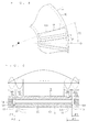
- FIG. 2 is a bottom view of a portion corresponding to one of the permanent magnets 20 of the field element shown in FIG. 1 .
- FIG. 3 is a cross-sectional view of the field element shown in FIG.
- circumferential direction a relative position of one permanent magnet 20 with respect to the magnetic plate 1 is indicated by a dot-dot-dash line.
- the magnetic plate 1 includes magnetic members 10, 12, 14 and 15 and the non-magnetic members 11 and 13.
- the magnetic plate 3 includes magnetic members 30, 32, 34 and 35 and non-magnetic members 31 and 33.
- the magnetic plate 3 has the same shape as the magnetic plate 1. Specifically, the magnetic members 30, 32, 34 and 35 and the non-magnetic members 31 and 33 have the same shapes as the magnetic members 10, 12, 14 and 15 and the non-magnetic members 11 and 13, respectively.
- the magnetic plate 1 will be representatively described, and description of the magnetic plate 3 will be omitted.
- the magnetic member 10 is in contact with a magnetic pole surface of one permanent magnet 20 in the rotation axis direction.
- the non-magnetic member 11 is, for example, an air space.
- the non-magnetic member 11 is adjacent to the magnetic member 10 in the circumferential direction, and overlaps a part of the one permanent magnet 20 in the rotation axis direction. More specifically, the non-magnetic members 11 are provided at positions corresponding to both ends of one permanent magnet 20 in the circumferential direction.
- the non-magnetic members 11 extend in a radial direction with the rotation axis being as the center (hereinafter, referred to as radial direction).
- the non-magnetic member 11 is illustrated as a concave portion which opens toward a side opposite to the permanent magnet 20 in the rotation axis direction, and a part of the magnetic member 10 is arranged between the permanent magnet 20 and the non-magnetic member 11. Not that it is not essential to arrange a part of the magnetic member 10 between the non-magnetic member 11 and the permanent magnet 20, but a working point of the permanent magnet 20 can be raised as a result of the above.
- the magnetic member 12 is adjacent to the non-magnetic member 11 on a side opposite to the magnetic member 10 in the circumferential direction. In addition, the magnetic member 12 extends in the radial direction.
- the non-magnetic member 13 is for example, an air space, and is adjacent to the magnetic member 12 on a side opposite to the non-magnetic member 11 in the circumferential direction.
- the non-magnetic member 13 is provided at a position so as not to overlap the permanent magnet 20 in the rotation axis direction, and is illustrated as a through hole in FIG. 3 .
- the non-magnetic member 13 extends in the radial direction with a substantially uniform width.
- the non-magnetic member 13 penetrates the magnetic plate 1 in the rotation axis direction, and thus the leakage flux of the permanent magnet 20 can be reduced. Note that in order to attain this effect, the width of the non-magnetic member 13 in the circumferential direction is desirably large to some extent.
- the non-magnetic member 13 is generally provided for reducing the leakage flux.
- the magnetic member 14 is positioned between the adjacent permanent magnets 20 in the circumferential direction and extends in the rotation axis direction.
- the magnetic member 14 has a projecting shape in which the magnetic member 14 projects in the rotation axis direction by a half of a thickness of the permanent magnet 20 in the rotation axis direction.
- the magnetic member 14 is continuous with the magnetic member 34 of the magnetic plate 3 in the rotation axis direction.
- the magnetic members 14 and 34 are not necessarily required, but a q-axis inductance can be increased by the magnetic members 14 and 34. As a result, reluctance torque can be improved.
- the magnetic member 15 couples the magnetic members 10 and 12 to each other on at least one end side of the non-magnetic member 11 in the radial direction, which is opposite to the rotation axis P. In the field element illustrated in FIGS. 1 to 3 , the magnetic member 15 couples the magnetic members 10 and 12 to each other on both end sides of the non-magnetic member 11 in the radial direction. Note that the magnetic member 15 is not necessarily required, but strength of the magnetic plate 1 can be improved by the magnetic member 15. In addition, the magnetic member 15 extends in the circumferential direction beyond the non-magnetic member 13 in the radial direction. Accordingly, the strength of the magnetic plate 1 can be improved further. Note that the width of the magnetic member 15 in the radial direction is desirably small. This is because leakage flux, which is generated by passing through the magnetic member 15, can be prevented.
- This field element is capable of forming a rotating electric machine together with armatures (not shown) which are disposed on both sides in the rotation axis direction thereof via a predetermined air gap.
- the field element is held in, for example, a manner using a columnar non-magnetic member shaft with the rotation axis P being as the center, a manner using a non-magnetic member boss, a manner in which the entire field element is held by a non-magnetic member, or a manner in which the entire field element is molded to be held.
- the permanent magnets 20 generate magnetic fluxes on surfaces of the magnetic plates 1 and 3 which are on sides opposite to the permanent magnets 20.
- the density distribution of the magnetic flux generated on the surface corresponding to one permanent magnet 20 is symmetrical with respect to an axis R which passes through a center of one permanent magnet in the circumferential direction (hereinafter, referred to as pole center) and is parallel to the radial direction. This is because, as shown in FIGS. 2 and 3 , a shape of portion corresponding to one permanent magnet 20 of the field element is symmetrical with respect to the axis R.
- pole gap polarities of the magnetic poles, which are provided in the magnetic plate 1 (or magnetic plate 3) by the permanent magnets 20 adjacent to each other in the circumferential direction, are different from each other. For this reason, as to the density distribution of the magnetic fluxes generated on the surfaces of the magnetic plates 1 and 3, the magnetic flux density becomes zero at a midpoint between the permanent magnets 20 adjacent to each other in the circumferential direction (hereinafter, referred to as pole gap).
- this magnetic flux density distribution includes a waveform in which a length between the adjacent pole gaps in the circumferential direction is a half-wavelength, and odd-order harmonic components in which the waveform is a fundamental component.
- Those harmonic components cause vibrations and noise.
- a fifth-order harmonic component and a seventh-order harmonic component have larger amplitude than a harmonic component of eleventh-order or more, and accordingly cause noise more easily.
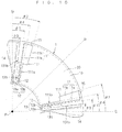
- 01 is an angle defined by a boundary 131 between the magnetic member 12 and the non-magnetic member 13 in the circumferential direction with respect to a reference axis Q with the rotation axis P being as the center
- ⁇ 2 is an angle defined by a boundary 111 between the magnetic member 10 and the non-magnetic member 11 in the circumferential direction with respect to the reference axis Q with the rotation axis P being as the center
- the reference axis Q is an axis which passes through the pole gap and is parallel to the radial direction.
- the non-magnetic members 11 and 13 are respectively provided at positions which satisfy: 0 ⁇ ⁇ ⁇ 1 ⁇ 180 / i ⁇ Pn and 180 / i ⁇ pn ⁇ ⁇ ⁇ 2 ⁇ 180 ⁇ 2 / i ⁇ Pn
- the number of pole pairs refers to the number of pairs of magnetic poles provided by the permanent magnet 20 about the rotation axis P.
- the boundaries 111 and 131 are assumed to extend substantially along the radial direction, but not limited thereto.
- the angle ⁇ 2 can be defined as an average angle in portions opposite to the armature.
- ⁇ 2 may be defined as an angled defined by a midpoint M in a portion of the boundary 111, which is opposite to the armature, with respect to the reference axis P with the rotation axis P being as the center.
- FIG. 5 shows a cross-section at a position where the non-magnetic members 11 and 13 are present in the magnetic field corresponding to one permanent magnet 20, which also shows an example of densities of the magnetic fluxes generated on the surfaces of the magnetic plates 1 and 3.
- the non-magnetic member 13 is located at a position which satisfies the relational expression (1), in the density distribution of the magnetic flux generated on the surface of the magnetic plate 1, the magnetic flux density decreases in this range. Accordingly, there is generated i-order harmonic component (zero at the pole gap) in which a valley is in this range. That is, i-order harmonic components are generated due to the non-magnetic member 13 provided for reducing the leakage flux.
- the non-magnetic member 11 is provided at a position which satisfies the relational expression (2). In the density distribution of the magnetic flux generated on the surface of the magnetic plate 1, the non-magnetic member 11 decreases the magnetic flux density in this range, whereby the i-order harmonic component (zero at the pole gap) in which the valley is in this range is generated.
- the magnetic plate 3 has the same shape as the magnetic plate 1, whereby it is possible to, in the similar manner, reduce i-order harmonic components of the density of the magnetic flux generated on the surface of the magnetic plate 3.
- the angle ⁇ 2 180/(i ⁇ Pn).
- the angle ⁇ 2 takes the smallest value, and thus the magnetic member 10 extends in the circumferential direction, thereby improving the density of the magnetic flux generated on the surface at the center of the magnetic member 10.
- the fifth-order harmonic component and the seventh-order harmonic component are generally large.
- the magnetic plate 3 has the same shape as the magnetic plate 1, but is not limited thereto.
- relative positions of the non-magnetic members 31 and 33 to the magnetic plate 3 can be different from relative positions of the non-magnetic members 11 and 13 to the magnetic plate 1, respectively. Specific description thereof will be given below.
- FIG. 6 shows a portion corresponding to one permanent magnet 20 of the conceptual top view of the field element shown in FIG. 1 .
- FIG. 7 is a cross-sectional view taken at a position where the non-magnetic members 31 and 33 are present in the circumferential direction of the field element shown in FIG. 6 .
- ⁇ 1 is an angle defined by a boundary 331 between the magnetic member 32 and the non-magnetic member 33 in the circumferential direction with respect to the reference axis Q with the rotation axis P being as the center
- ⁇ 2 is an angle defined by a boundary 311 between the magnetic member 30 and the non-magnetic member 31 in the circumferential direction with respect to the reference axis Q with the rotation axis P being as the center.
- the non-magnetic members 31 and 33 may be respectively provided at positions which satisfy: 0 ⁇ ⁇ ⁇ 1 ⁇ 180 / K ⁇ Pn and 180 / K ⁇ Pn ⁇ ⁇ ⁇ 2 ⁇ 180 ⁇ 2 / K ⁇ Pn
- the magnetic plate 3 is not necessarily required to include the non-magnetic member 31.
- the non-magnetic member 31 does not need to be provided.
- the non-magnetic member 33 it is preferred that the non-magnetic member 33 be provided so as to pierce through the magnetic plate 3 in the rotation axis direction.
- the shape in the portion corresponding to one permanent magnet 20 is symmetrical with respect to the axis R in any field elements described above, and also if the shapes in the portions corresponding to all permanent magnets 20 are the same, it is possible to prevent the field element from tilting with respect to the rotation axis P. As a result, air gap accuracy between the armature and the field element can be maintained, whereby it is possible to prevent characteristics of the rotating electric machine from deteriorating due to the tilt.
- the magnetic plates 1 and 3 are desirably formed of a dust core.
- the magnetic plates 1 and 3 are formed of a laminated steel sheet or the like, through holes are provided in the laminated steel sheet by punching for providing the non-magnetic members 11 and 13 in the magnetic plate 1.
- a punching member for forming such through hole is worn away through several tens of thousands of times of punching, and eventually cannot be used.
- the magnetic plates 1 and 3 can be formed of a dust core, and thus there arises no problem regarding durability of the punching member as described above. Accordingly, productivity can be improved.
- the magnetic plates 1 and 3 are formed of a dust core
- the magnetic plates 1 and 3 preferably have a small step in thickness in the rotation axis direction.
- press forming needs to be repeatedly performed when the step is large, and productivity is decreased in some cases.
- a pair of the magnetic members 14 and 34 may be formed separately from the magnetic plates 1 and 3. In such a case, productivity can be improved.
- assembly or inspection is performed using a gap gage for obtaining a desired air gap. Specifically, assembly or inspection is performed while the gap gage is inserted between the armature and the field element from the outer periphery side of the magnetic plates 1 and 3. In this case, when the outer peripheries of the magnetic plates 1 and 3 continue by the magnetic members 15 and 35, the gap gage can be inserted from any direction. Accordingly, assembly or inspection can be performed with ease. Note that in terms of characteristics of the rotating electric machine, the magnetic members 15 and 35 are desired not to be opposed to the core of the armature in the rotation axis direction.
- magnetic plates 1 and 3 continue in the circumferential direction in the first embodiment, but any one thereof may be separated from the other thereof for each permanent magnet 20. In this case, it is possible to further reduce the leakage flux on the separated magnetic plate side.
- FIG. 8 is a conceptual bottom view of this field element.
- FIG. 9 is a cross-sectional view taken at a position where the non-magnetic members 11 and 13 are present in the circumferential direction of the field element shown in FIG. 8.
- FIGS. 8 and 9 each show a portion corresponding to one permanent magnet 20.
- the non-magnetic member 11 includes non-magnetic member parts 11a and 11b
- the non-magnetic member 13 includes non-magnetic member parts 13a and 13b
- the non-magnetic member 31 includes non-magnetic member parts 31a and 31b
- the non-magnetic member 33 includes non-magnetic member parts 33a and 33b.
- the non-magnetic member part 11a is, for example, an air space.
- the non-magnetic member part 11b is, for example, an air space and is adjacent to the non-magnetic member part 11a on the magnetic member 10 side in the circumferential direction.
- the non-magnetic member parts 11a and 11b are different from each other in length in the rotation axis direction (that is, thickness in the rotation axis direction; hereinafter, referred to as thickness). More specifically, the thickness of the non-magnetic member part 11b is smaller than the thickness of the non-magnetic member part 11a.
- the non-magnetic member part 13a is, for example, an air space.
- the non-magnetic member part 13b is, for example, an air space and is adjacent to the non-magnetic member part 13a on the magnetic member 10 side in the circumferential direction.
- the non-magnetic member parts 13a and 13b are different from each other in thickness. More specifically, the thickness of the non-magnetic member part 13b is smaller than the thickness of the non-magnetic member part 13a. Note that the thickness of the non-magnetic member part 13a is the same as the thickness of the magnetic member 10. In other words, the non-magnetic member part 13a pierces through the magnetic plate 1 in the rotation axis direction.
- ⁇ 3 is an angle defined by a boundary 131b between the non-magnetic member part 13a and the non-magnetic member part 13b in the circumferential direction with respect to the reference axis Q with the rotation axis P being as the center
- ⁇ 4 is an angle defined by a boundary 111b between the non-magnetic member part 11a and the non-magnetic member part 11b in the circumferential direction with respect to the reference axis Q with the rotation axis P being as the center.
- the non-magnetic member parts 11a, 11b, 13a and 13b are respectively provided at positions which satisfy: 0 ⁇ ⁇ ⁇ 1 ⁇ 180 / i ⁇ Pn 180 / i ⁇ Pn ⁇ ⁇ ⁇ 2 ⁇ 180 ⁇ 2 / i ⁇ Pn 0 ⁇ ⁇ ⁇ 3 ⁇ 180 / j ⁇ Pn 180 / j ⁇ Pn ⁇ ⁇ ⁇ 3 ⁇ 180 ⁇ 2 / j ⁇ Pn and ⁇ ⁇ 3 ⁇ ⁇ ⁇ 1 ⁇ ⁇ ⁇ 4 ⁇ ⁇ ⁇ 2
- j-order harmonic components which are deviated from each other in phase by 180° (half-wavelength) due to the non-magnetic member parts 11a and 13a, are generated on the surface of the magnetic plate 1. Accordingly, they cancel each other, whereby it is possible to reduce the j-order harmonic components in the density distribution of the magnetic flux generated on the surface of the magnetic plate 1. Therefore, it is possible to reduce not only the i-order harmonic components but also the j-order harmonic components of the induced voltage generated in the armature, and hence vibrations and noise can be reduced further.
- the non-magnetic member part 11b having a small thickness in the rotation axis direction is large in the circumferential direction, with the result that the density of the magnetic flux generated on the surface of the magnetic plate 1 can be improved.
- non-magnetic member 11 (13) includes two non-magnetic member parts 11a and 11b (13a and 13b) which are different from each other in thickness, but is not limited thereto, and may include three non-magnetic member parts different from each other in thickness. In this case, harmonic components of three orders can be reduced. It goes without saying that four or more non-magnetic member parts may be provided.
- the magnetic plate 3 is not limited to have the shape same as the magnetic plate 1 as in the first embodiment. Specifically, when it is assumed that ⁇ 3 is an angle defined by a boundary 331 b between non-magnetic member part 33a and the non-magnetic member part 33b in the circumferential direction with respect to the reference axis Q with the rotation axis P being as the center, that ⁇ 4 is an angle defined by a boundary 311b between non-magnetic member part 31a and the non-magnetic member part 31 b in the circumferential direction with respect to the reference axis Q with the rotation axis P being as the center, and that L is an odd number equal to or more than three which is different from each other, in which L is a value different from K, the non-magnetic member parts 31a, 31b, 33a and 33b may be provided at positions which satisfy: 0 ⁇ ⁇ ⁇ 1 ⁇ 180 / K ⁇ Pn 180 / K ⁇ Pn ⁇ ⁇ ⁇ 2 ⁇ 180
- the non-magnetic members 31 and 33 may include three or more non-magnetic member parts different from each other in thickness.
- i, j, K or L may be adequately set to five or seven, an effect is particularly enhanced in a case where the fifth-order harmonic component and the seventh-order harmonic component are large (for example, case where the armature is formed by concentrated winding).
- FIG. 10 shows a portion corresponding to one permanent magnet 20 of a bottom view of this field element. Note that the conceptual cross section at the position where the non-magnetic members 11 and 13 are present in the circumferential direction of the field element shown in FIG. 10 is substantially the same as FIG. 3 .
- the non-magnetic member parts 11a and 11b are different from each other in length in the radial direction (hereinafter, merely referred to as length). Specifically, the non-magnetic member part 11b has the length shorter than the length of the non-magnetic member part 11a. Note that the non-magnetic member parts 11a and 11b have the same thickness.
- the non-magnetic member parts 13a and 13b are different from each other in length. Specifically, the non-magnetic member part 13b has the length shorter than the length of the non-magnetic member part 13a. Note that the non-magnetic member parts 13a and 13b have the same thickness as the magnetic member 10. In other words, the non-magnetic member parts 13a and 13b pierce through the magnetic plate 1 in the rotation axis direction.
- the magnetic plate 3 has the same shape as the magnetic plate 1, and the non-magnetic member parts 11a, 11b, 13a and 13b are provided at positions which satisfy the relational expressions (1), (2), (5), (6) and (7). Accordingly, it is possible to reduce the i-order harmonic component and the j-order harmonic component of the induced voltage generated in the armature.
- the non-magnetic member parts 31a, 31b, 33a and 33b to the magnetic plate 3 are different from the relative positions of the non-magnetic member parts 11a, 11b, 13a and 13b to the magnetic plate 1
- the non-magnetic member parts 31a, 31b, 33a and 33b are provided at positions which satisfy the relational expressions (3), (4), (8), (9) and (10).
- non-magnetic members 11, 13, 31 and 33 each may include four or more non-magnetic member parts.
- the thicknesses thereof in the rotation axis direction or the lengths thereof in the radial direction may be different from each other.
- FIG. 11 is a conceptual perspective view showing a field element of this embodiment, which is disassembled along the rotation axis P.
- This field element includes the magnetic plate 1, the permanent magnets 20 and a magnetic plate 4.
- the magnetic plate 1 is the magnetic plate 1 which has been described in any of the first to third embodiments.
- FIG. 11 shows the magnetic plate which does not include the magnetic members 14 and 15 of the magnetic plate 1 described in the second embodiment. That is, the magnetic plate 1 is separated in the circumferential direction for each permanent magnet 20.
- the magnetic plate 4 has a flat plate shape having a circular circumference with the rotation axis P being as the center. In addition, the magnetic plate 4 has a thickness sufficient for functioning as a so-called back yoke.
- the armature is disposed with a predetermined gap on the magnetic plate 1 side in the rotational axis direction, and thus this filed element is capable of forming a rotating electric machine together with the armature. Even in this case, it is possible to reduce the i-order harmonic component and the j-order harmonic component of the induced voltage generated in the armature.
- the magnetic plate 1 is separated in the circumferential direction for each permanent magnet 20, whereby it is possible to further reduce the leakage flux of the permanent magnet 20.
Landscapes
- Engineering & Computer Science (AREA)
- Power Engineering (AREA)
- Permanent Field Magnets Of Synchronous Machinery (AREA)
- Iron Core Of Rotating Electric Machines (AREA)
Applications Claiming Priority (2)
| Application Number | Priority Date | Filing Date | Title |
|---|---|---|---|
| JP2007109351A JP2008271670A (ja) | 2007-04-18 | 2007-04-18 | 界磁子 |
| PCT/JP2008/056943 WO2008132996A1 (fr) | 2007-04-18 | 2008-04-08 | Pièce de champ |
Publications (2)
| Publication Number | Publication Date |
|---|---|
| EP2139091A1 true EP2139091A1 (fr) | 2009-12-30 |
| EP2139091A4 EP2139091A4 (fr) | 2017-02-22 |
Family
ID=39925455
Family Applications (1)
| Application Number | Title | Priority Date | Filing Date |
|---|---|---|---|
| EP08740046.1A Withdrawn EP2139091A4 (fr) | 2007-04-18 | 2008-04-08 | Piece de champ |
Country Status (7)
| Country | Link |
|---|---|
| US (1) | US8013700B2 (fr) |
| EP (1) | EP2139091A4 (fr) |
| JP (1) | JP2008271670A (fr) |
| KR (1) | KR101072649B1 (fr) |
| CN (1) | CN101622772B (fr) |
| AU (1) | AU2008245193B2 (fr) |
| WO (1) | WO2008132996A1 (fr) |
Families Citing this family (1)
| Publication number | Priority date | Publication date | Assignee | Title |
|---|---|---|---|---|
| EP2676356A1 (fr) * | 2011-02-17 | 2013-12-25 | CERN - European Organization For Nuclear Research | Système et procédé permettant de positionner et de fixer un certain nombre d'objets les uns par rapport aux autres |
Family Cites Families (18)
| Publication number | Priority date | Publication date | Assignee | Title |
|---|---|---|---|---|
| JP2513109Y2 (ja) * | 1988-08-10 | 1996-10-02 | 株式会社東芝 | モ―タ装置 |
| JP3487667B2 (ja) * | 1995-03-15 | 2004-01-19 | 松下電器産業株式会社 | ロータの構造 |
| JP3914293B2 (ja) | 1997-01-13 | 2007-05-16 | 松下電器産業株式会社 | 永久磁石モータ |
| JPH1198731A (ja) | 1997-07-22 | 1999-04-09 | Matsushita Electric Ind Co Ltd | 永久磁石を埋設したロータを用いたモータ |
| US6008559A (en) * | 1997-07-22 | 1999-12-28 | Matsushita Electric Industrial Co., Ltd. | Motor using a rotor including an interior permanent magnet |
| JPH11103546A (ja) * | 1997-09-29 | 1999-04-13 | Fujitsu General Ltd | 永久磁石電動機 |
| DE19933009A1 (de) * | 1998-07-24 | 2000-02-10 | Matsushita Electric Industrial Co Ltd | Motor mit interne Permanentmagneten enthaltendem Rotor und einen solchen Motor verwendende Antriebseinheit |
| JP3769943B2 (ja) | 1998-08-21 | 2006-04-26 | 松下電器産業株式会社 | 永久磁石ロータ |
| JP2002044888A (ja) | 2000-07-25 | 2002-02-08 | Daikin Ind Ltd | モータおよびモータ制御装置 |
| JP2002078260A (ja) * | 2000-08-31 | 2002-03-15 | Toyota Motor Corp | 永久磁石電動機 |
| JP4349089B2 (ja) * | 2003-11-10 | 2009-10-21 | 株式会社エクォス・リサーチ | アキシャルギャップ回転電機 |
| WO2005096470A1 (fr) * | 2004-03-31 | 2005-10-13 | Daikin Industries, Ltd. | Moteur, ventilateur, compresseur et conditionneur d'air |
| JP2006230184A (ja) * | 2005-01-18 | 2006-08-31 | Daikin Ind Ltd | 電機子、モータ及び圧縮機並びにそれらの製造方法 |
| KR100904353B1 (ko) * | 2005-01-19 | 2009-06-23 | 다이킨 고교 가부시키가이샤 | 회전자, 축방향 갭형 모터, 모터의 구동 방법, 압축기 |
| JP4692090B2 (ja) * | 2005-06-16 | 2011-06-01 | 株式会社富士通ゼネラル | アキシャルエアギャップ型電動機 |
| JP4904736B2 (ja) * | 2005-07-21 | 2012-03-28 | 日産自動車株式会社 | 回転電機の固定子 |
| JP2007097387A (ja) | 2005-08-31 | 2007-04-12 | Toshiba Corp | 回転電機 |
| JP2007089270A (ja) * | 2005-09-20 | 2007-04-05 | Toyota Central Res & Dev Lab Inc | アキシャル型電動機及びそのロータ |
-
2007
- 2007-04-18 JP JP2007109351A patent/JP2008271670A/ja active Pending
-
2008
- 2008-04-08 KR KR1020097018703A patent/KR101072649B1/ko not_active Expired - Fee Related
- 2008-04-08 WO PCT/JP2008/056943 patent/WO2008132996A1/fr not_active Ceased
- 2008-04-08 EP EP08740046.1A patent/EP2139091A4/fr not_active Withdrawn
- 2008-04-08 CN CN2008800071692A patent/CN101622772B/zh not_active Expired - Fee Related
- 2008-04-08 AU AU2008245193A patent/AU2008245193B2/en not_active Ceased
- 2008-04-08 US US12/595,172 patent/US8013700B2/en not_active Expired - Fee Related
Non-Patent Citations (1)
| Title |
|---|
| See references of WO2008132996A1 * |
Also Published As
| Publication number | Publication date |
|---|---|
| CN101622772B (zh) | 2011-12-07 |
| CN101622772A (zh) | 2010-01-06 |
| JP2008271670A (ja) | 2008-11-06 |
| AU2008245193B2 (en) | 2011-03-31 |
| WO2008132996A1 (fr) | 2008-11-06 |
| KR101072649B1 (ko) | 2011-10-11 |
| KR20090115955A (ko) | 2009-11-10 |
| US8013700B2 (en) | 2011-09-06 |
| EP2139091A4 (fr) | 2017-02-22 |
| US20100164664A1 (en) | 2010-07-01 |
| AU2008245193A1 (en) | 2008-11-06 |
Similar Documents
| Publication | Publication Date | Title |
|---|---|---|
| CN108075585B (zh) | 旋转电机 | |
| US8362668B2 (en) | Rotor for rotating electrical machine | |
| CN104704714B (zh) | 永磁体埋入型电动机 | |
| US9893575B2 (en) | Permanent-magnet-embedded electric motor and method for manufacturing same | |
| US20020140308A1 (en) | Brushless DC motor and method of manufacturing brushless DC motor | |
| US9923436B2 (en) | Rotor for a rotary electric machine | |
| JP5382012B2 (ja) | 回転電機用回転子、および、その製造方法 | |
| CN102369650B (zh) | 永磁式旋转电机的转子 | |
| JP5057171B2 (ja) | 埋込磁石型モータ | |
| JP2010193660A (ja) | 分割型回転子及び電動機 | |
| US12191713B2 (en) | Rotor of rotary electric machine | |
| JP2008193809A (ja) | 埋込磁石型モータ | |
| JP6112970B2 (ja) | 永久磁石式回転電機 | |
| JP2013046466A (ja) | 回転子 | |
| JP2013236418A (ja) | 回転電気機械 | |
| JP2019180214A (ja) | モータ | |
| EP2139091A1 (fr) | Piece de champ | |
| US11139705B2 (en) | Electric motor | |
| JPWO2020017189A1 (ja) | モータおよびモータの製造方法 | |
| KR20070106925A (ko) | 스테핑 모터 | |
| JP2007143305A (ja) | コアの製造方法、ステータの製造方法及びモータの製造方法 | |
| JP2016187283A (ja) | 磁石埋込型ロータ及び磁石埋込型ロータの製造方法 | |
| US12294243B2 (en) | Rotating electric machine | |
| US20240405624A1 (en) | Rotor and motor | |
| WO2024013929A1 (fr) | Moteur électrique synchrone à aimants permanents |
Legal Events
| Date | Code | Title | Description |
|---|---|---|---|
| PUAI | Public reference made under article 153(3) epc to a published international application that has entered the european phase |
Free format text: ORIGINAL CODE: 0009012 |
|
| 17P | Request for examination filed |
Effective date: 20091015 |
|
| AK | Designated contracting states |
Kind code of ref document: A1 Designated state(s): AT BE BG CH CY CZ DE DK EE ES FI FR GB GR HR HU IE IS IT LI LT LU LV MC MT NL NO PL PT RO SE SI SK TR |
|
| DAX | Request for extension of the european patent (deleted) | ||
| RA4 | Supplementary search report drawn up and despatched (corrected) |
Effective date: 20170123 |
|
| RIC1 | Information provided on ipc code assigned before grant |
Ipc: H02K 1/22 20060101AFI20170117BHEP Ipc: H02K 1/27 20060101ALI20170117BHEP |
|
| STAA | Information on the status of an ep patent application or granted ep patent |
Free format text: STATUS: THE APPLICATION HAS BEEN WITHDRAWN |
|
| 18W | Application withdrawn |
Effective date: 20170301 |