EP2139257A1 - Synchronization method, communication handover method, radio network and node - Google Patents
Synchronization method, communication handover method, radio network and node Download PDFInfo
- Publication number
- EP2139257A1 EP2139257A1 EP08734147A EP08734147A EP2139257A1 EP 2139257 A1 EP2139257 A1 EP 2139257A1 EP 08734147 A EP08734147 A EP 08734147A EP 08734147 A EP08734147 A EP 08734147A EP 2139257 A1 EP2139257 A1 EP 2139257A1
- Authority
- EP
- European Patent Office
- Prior art keywords
- interface
- ran node
- node
- information
- handover
- Prior art date
- Legal status (The legal status is an assumption and is not a legal conclusion. Google has not performed a legal analysis and makes no representation as to the accuracy of the status listed.)
- Granted
Links
Images



Classifications
-
- H—ELECTRICITY
- H04—ELECTRIC COMMUNICATION TECHNIQUE
- H04W—WIRELESS COMMUNICATION NETWORKS
- H04W36/00—Hand-off or reselection arrangements
- H04W36/0005—Control or signalling for completing the hand-off
- H04W36/0055—Transmission or use of information for re-establishing the radio link
- H04W36/0079—Transmission or use of information for re-establishing the radio link in case of hand-off failure or rejection
-
- H—ELECTRICITY
- H04—ELECTRIC COMMUNICATION TECHNIQUE
- H04W—WIRELESS COMMUNICATION NETWORKS
- H04W36/00—Hand-off or reselection arrangements
- H04W36/02—Buffering or recovering information during reselection ; Modification of the traffic flow during hand-off
-
- H—ELECTRICITY
- H04—ELECTRIC COMMUNICATION TECHNIQUE
- H04W—WIRELESS COMMUNICATION NETWORKS
- H04W92/00—Interfaces specially adapted for wireless communication networks
- H04W92/04—Interfaces between hierarchically different network devices
- H04W92/045—Interfaces between hierarchically different network devices between access point and backbone network device
-
- H—ELECTRICITY
- H04—ELECTRIC COMMUNICATION TECHNIQUE
- H04W—WIRELESS COMMUNICATION NETWORKS
- H04W36/00—Hand-off or reselection arrangements
- H04W36/0005—Control or signalling for completing the hand-off
- H04W36/0055—Transmission or use of information for re-establishing the radio link
- H04W36/0058—Transmission of hand-off measurement information, e.g. measurement reports
-
- H—ELECTRICITY
- H04—ELECTRIC COMMUNICATION TECHNIQUE
- H04W—WIRELESS COMMUNICATION NETWORKS
- H04W92/00—Interfaces specially adapted for wireless communication networks
- H04W92/16—Interfaces between hierarchically similar devices
- H04W92/20—Interfaces between hierarchically similar devices between access points
Definitions
- the present invention relates to the communication field, and in particular, to an interface information synchronization method, a communication handover method, a radio network, and a Radio Access Network (RAN) node.
- RAN Radio Access Network
- the Long Term Evolution/System Architecture Evolution (LTE/SAE) network system project is the biggest new technology development project launched by the 3rd Generation Partnership Project (3GPP) in recent years.
- the core of such a technology is Orthogonal Frequency Division Multiplexing (OFDM)/Frequency Division Multiple Access (FDMA), and therefore, such a technology has some 4 th Generation (4G) features and is regarded as a quasi-4G technology.
- FIG. 1 shows an architecture of an LTE/SAE in the prior art.
- the LTE/SAE network system includes an evolved Node B (eNB, an evolved RAN node) and the Mobility Management Entity/Serving System Architecture Evolution Gateway (MME/SGW) that manages the RAN nodes.
- the interface between the MME/SGW and the eNB is an S1 interface
- the interface between eNBs is an X2 interface.
- the communication handover process falls into two types: handover from a source eNB to a target eNB through an X2 interface; and handover from a source eNB to a target eNB through an S 1 interface, as described below:
- Handover through an X2 interface In the handover process, the source eNB and the target eNB are governed by the same MME; the MME is unchanged; and the source eNB sends a Handover Request message to the target eNB through an X2 interface to perform handover.
- the handover process involves no MME, and is known as handover through an X2 interface.
- the handover performed through an X2 interface involves use of an S1 interface.
- Handover through an S 1 interface When the MME involved in the handover process changes, namely, when the source eNB and the target eNB are not governed by the same MME, the source eNB needs to send a Handover Request message through an S 1 interface, which is known as handover through an S 1 interface.
- the Handover Request is sent through an X2 interface so long as an X2 interface connection exists. If the target eNB finds it impossible to perform handover through an X2 interface, for example, if it is determined that the same MME connection is lacking, the target eNB sends a handover failure message to the source eNB.
- the handover failure message carries the corresponding cause value, and instructs the source eNB to send a Handover Require message to the MME again through an S 1 interface.
- the inventor finds at least the following defects in the prior art:
- the present invention discloses an interface information synchronization method, a communication handover method, a radio network, and a RAN node, thus improving the efficiency of communication handover.
- An interface information synchronization method is disclosed in an embodiment of the present invention.
- the method includes: judging whether a condition for initiating interface information update is fulfilled; sending information about an S 1 interface between a RAN node and a core network node, and/or information about an X2 interface between the RAN node and a neighboring RAN node to the neighboring RAN node if the condition for initiating interface information update is fulfilled.
- a communication handover method is disclosed in an embodiment of the present invention. The method includes:
- the first RAN node includes:
- the second RAN node includes:
- a communication handover method is disclosed in an embodiment of the present invention.
- the method includes:
- the RAN node sends the changed S 1 or X2 interface configuration/state information to the neighboring RAN node, notifying the neighboring RAN node to modify the corresponding S1 or X2 interface configuration table.
- RAN nodes in the communication network have the latest S1 or X2 interface configuration table.
- the source RAN node searches for the configuration information of the target RAN node in the S1 or X2 interface configuration table.
- a procedure is used to perform handover from a source RAN node to a target RAN node using X2 interface when S1 interface exists between the target RAN node and a serving core network node of the source RAN node. Otherwise the S1-based handover procedure is used.
- a communication handover method is disclosed in an embodiment of the present invention.
- the method includes:
- the RAN node may be an eNB, and the core network node may be an MME.
- An interface information synchronization method is disclosed in an embodiment of the present invention.
- the method includes:
- the S1 and/or X2 interface information of the RAN node is sent to the neighboring RAN node when the condition is fulfilled.
- the neighboring RAN node hands over to the RAN node, the neighboring RAN node can determine whether an S1 interface exists between the neighboring RAN node itself and the core network according to its own S 1 interface information and the received S 1 interface information, and can accurately determine the interface available for handover according to the received X2 interface information. Therefore, the proper interface is selected accurately and quickly, the trouble of judging whether the X2 interface is available for handover in the case of unawareness of the interface information in the prior art is avoided, the handover efficiency is improved, and the system load is reduced.
- the source RAN node when handover occurs, the source RAN node reads the stored interface handover table (the interface handover table includes the information indicating whether the handover can be performed through an S 1 interface to the target RAN node).
- the source RAN node performs handover through the S 1 interface if the interface handover table indicates that the handover can be performed through the S1 interface to the target RAN node; otherwise, the source RAN node performs handover through the X2 interface. Therefore, the proper interface is selected accurately and quickly.
- the trouble of judging whether the X2 interface is available for handover in the case of unawareness of the interface information in the prior art is avoided, the handover efficiency is improved, and the system load is reduced.
- the source RAN node reads interface information when handover occurs, the interface information includes the information about whether an X2 interface exists between the source RAN node and the target RAN node and/or the information about whether an S 1 interface exists between the serving core network node of the source RAN node and the target RAN node.
- the source RAN node performs handover through the X2 interface if the interface information indicates that an X2 interface exists between the source RAN node and the target RAN node and/or an S 1 interface exists between the serving core network node of the source RAN node and the target RAN node; or else performs handover through the S1 interface. Therefore, the proper interface is selected accurately and quickly.
- the trouble of judging whether the X2 interface is available for handover in the case of unawareness of the interface information in the prior art is avoided, the handover efficiency is improved, and the system load is reduced.
- the interface information or the interface handover table is read when handover occurs, a proper interface is selected for handover according to the interface handover requirement recorded in the interface handover table or according to the interface which is determined as available for handover in view of the interface information.
- the judging mode is: A Handover Request is sent through the X2 interface if the interface information includes the information about the X2 interface exists between the source RAN node and the target RAN node and the information about the S1 interface exists between the serving core network node of the source RAN node and the target RAN node; otherwise, the Handover Request is sent through an S1 interface. Therefore, the proper interface is selected accurately and quickly.
- the trouble of judging whether the X2 interface is available for handover in the case of unawareness of the interface information in the prior art is avoided, the handover efficiency is improved, and the system load is reduced.
- FIG. 2 is a flowchart of a communication handover method in an embodiment of the present invention. The process includes at least the following steps:
- the S 1 and the X2 interface information may exist in the form of S 1 and X2 interface configuration table, and may be stored on the source RAN node.
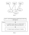
- RAN node 1 is adjacent to RAN nodes 2 and 3 in the network, and an X2 interface exists between them.
- Table 1 is an exemplary structure of an S 1 or X2 interface configuration table in the network.
- RAN node 1 is adjacent to RAN nodes 2 and 3, and an X2 interface exists between them.
- RAN node 1 may store the following table: Table 1: S 1 or X2 interface configuration table of RAN node 1 RAN node core network node 1 core network node 2 core network node 3 RAN node 2 0 1 1 RAN node 3 0 0 1
- the first column of the table is the information about the neighboring RAN node.
- the first column includes RAN node 2 and RAN node 3.
- An X2 interface exists between RAN node 1 and RAN nodes 2 and 3. If the column has no name of a RAN node, it indicates that no X2 interface exists between RAN node 1 and the RAN node.
- the first row of the table indicates the relevant core network nodes, and the content below the second row indicates whether an S 1 interface exists between each neighboring RAN node and the relevant core network node. "1" indicates that an S1 interface exists between a RAN node and the relevant core network node; and "0" indicates that no S 1 interface exists between them.
- the foregoing table reveals that: An S1 interface exists between RAN node 2 and core network nodes 2 and 3, but no S1 interface exists between RAN node 2 and core network node 1; an S1 interface exists between RAN node 3 and core network node 3, but no S1 interface exists between RAN node 3 and core network node 1 or 2.
- the source RAN node may infer whether an S 1 interface exists between the serving core network of the source RAN node and other neighboring RAN nodes. For example, if RAN node 2 and the serving core network node 2 of RAN node 1 correspond to the position "1" in the table but RAN node 1 already knows that an S 1 interface exists between RAN node 1 and core network node 2, it is inferred that an S1 interface exists between RAN node 1 and the serving core network node 2 of RAN node 2.
- the first column of the table indicates whether an X2 interface exists between the source RAN node and other neighboring RAN nodes.
- the second row of the table indicates whether an S1 interface connection exists between the neighboring RAN node and the core network node.
- the source RAN node may infer whether an S1 interface exists between the serving core network node of the source RAN node and the neighboring RAN node according to the S 1 interface information of the source RAN node and the S 1 interface information below the second row in the table.
- other neighboring RAN nodes also store similar configuration tables for communication handover.
- Table 2 and Table 3 are examples: Table 2: S1 or X2 interface configuration table of RAN node 2 RAN node Core network node 1 Core network node 2 Core network node 3 RAN node 1 1 1 0 Table 3: S1 or X2 interface configuration table of RAN node 3 RAN node core network node 1 core network node 2 core network node 3 RAN node 1 1 1 0
- the RAN node may also add its own S1 interface information into the first row of the foregoing configuration table.
- the second row and the content below it are the information about the neighboring RAN node, as shown in Table 4:
- RAN node 1 serves as a source RAN node, it is easy to determine whether an S1 interface exists between the source RAN node and a core network node, and whether an S1 interface exists between another neighboring RAN node and the core network node.
- the source RAN node When handover needs to occur on the source RAN node, the source RAN node reads the S1 and X2 interface configuration table stored locally first, and then performs the following steps:
- the RAN node in the radio network judges whether an S 1 interface exists between the RAN node and the core network according to the S 1 interface information of the RAN node and the received S 1 interface information, and can select a proper interface accurately and quickly according to the received X2 interface information. Therefore, the trouble of judging whether the X2 interface is available for handover after receiving a Handover Request in the prior art is avoided, the handover speed is improved, and the system load is reduced.
- the handover fails if the Handover Request is sent through the X2 interface directly. Therefore, this step is added to judge the X2 interface link state first. If the X2 interface link state is abnormal, the Handover Request is sent through an S 1 interface, thus improving the handover success ratio.
- a state value is added on the basis of the S1 or X2 interface configuration table to indicate whether the X2 or S 1 interface links are normal. Specifically, a parameter may be added to indicate whether the link is available or existent.
- Table 5 gives an example: Table 5: S1 or X2 interface configuration table on RAN node 1 RAN node core network node 1 core network node 2 core network node 3 X2 RAN node 2 0 1 2 1 RAN node 3 0 0 1 2
- the "X2" column is additional, the "0" value indicates that no link exists, "1" indicates normal, and "2" indicates link failure.
- the parameters in Table 5 mean that: The X2 link between RAN node 1 and RAN node 2 is normal; the X2 link between RAN node 1 and RAN node 3 is unavailable; no S1 connection exists between RAN node 2 and core network node 1, the S1 connection between RAN node 2 and core network node 2 is normal, and the S1 connection between RAN node 2 and core network node 3 is unavailable; and the X2 link between RAN node 1 and RAN node 3 is unavailable.
- the "X2" column may exist in another table.
- the "X2" column is optional, and is useful in step 201.
- step B may be performed before step C:
- source RAN node 1 when source RAN node 1 needs to hand over to target RAN node 2, source RAN node 1 searches Table 5. If the X2 state value is "1", it indicates that the X2 link is normal. Afterward, the state of the core network node connected with RAN node 2 is checked. If the state value of core network node 2 is "1", it indicates that the S 1 link is normal, and the handover is performed through the X2 interface.
- an additional option may be set in the S 1 or X2 interface configuration table to indicate whether the handover needs to be performed through the S 1 interface or the X2 interface. If the S 1 and X2 interface configuration table includes the information about the X2 interface between the source RAN node and the target RAN node and the information about the S1 interface between the serving core network node of the source RAN node and the target RAN node, information is set to indicate that the handover needs to be performed through the X2 interface; otherwise, information is set to indicate that the handover needs to be performed through the S 1 interface.
- a simpler S 1 interface handover table is generated dynamically on the basis of the S 1 or X2 interface configuration table.
- the S 1 interface handover table indicates whether the handover to the target RAN node needs to be performed through the S 1 interface.
- the S 1 interface handover table directly decides whether the S 1 interface handover process or the X2 interface handover process applies.
- the S 1 interface handover table falls into the following two types:
- the value of the S 1 handover option in the interface handover table is 0, indicating that the handover needs to be performed through the X2 interface instead of the S1 interface; otherwise, the value is 1, indicating that the handover needs to be performed through the S1 interface.
- the S1 interface link state may be considered at the same time. For example, when the S 1 interface link state is normal, the value of the option is 0; otherwise, the value of the option is 1.
- this table may be searched for the value corresponding to the target RAN node and the serving core network node of the source RAN node, and the handover selection is made according to such a value directly, without the need of searching the S1 or X1 interface configuration table.
- Table 6 may be generated by reference to Table 5.
- the source RAN node After receiving the X2 or S 1 interface information of the neighboring RAN node, the source RAN node generates an X2 or S 1 interface configuration table described above, and then generates an S 1 interface handover table (as shown in Table 6) according to whether an S 1 interface connection exists between the source RAN node and the serving core network node of the source RAN node. That is, if the state indicated in the "core network node" column in Table 5 is "available", the handover needs to be performed through the X2 interface; otherwise, the handover needs to be performed through the S 1 interface.
- the interface handover table includes only the S 1 interface option of different core network nodes between two RAN nodes, and is simpler.
- the principles are as follows:
- the interface handover table is set in the following way:
- the source RAN node and the target RAN node are not connected to the same core network node through an S1 interface, it is only necessary to set information in the interface handover table to indicate that the handover to the target RAN node needs to be performed through an S1 interface.
- the source RAN node After receiving the S 1 interface information, the source RAN node compares the received S 1 interface information with its own S 1 interface information. If one MME/multiple MMEs/all MMEs are the same, it indicates that the source RAN node and the target RAN node are in the same MME pool; otherwise, it indicates that the source RAN node and the target RAN node are not in the same MME pool.
- the RAN nodes not in the same MME pool are put into the interface handover table.
- the S 1 information includes configuration information, and optionally, link state information. As shown in Table 7, RAN node 2 and the source RAN node are not in the same MME pool: Table 7: Interface handover table 2 Target RAN node State eNB2 1
- the communication handover process includes at least the following steps:
- an interface information synchronization method in the second embodiment of the present invention is put forward. As shown in FIG. 5 , the method includes the following steps:
- Step 502 If the condition for initiating interface information update is fulfilled, the information about the S1 interface between the RAN node and the core network node, and/or the information about the X2 interface between the RAN node and the neighboring RAN node, is sent to the neighboring RAN node.
- a message is sent to the neighboring RAN node through the X2 interface, where the message carries the information about the S 1 interface and/or the X2 interface of the RAN node.
- the information about the S 1 interface and/or the X2 interface of the RAN node may be a special signaling (such as a Config Info message) sent to neighboring RAN node 1, or may be added into another automatic configuration message sent to neighboring RAN node 1.
- a special signaling such as a Config Info message
- the information about the S1 interface and/or the X2 interface of the RAN node includes: information about the X2 interface between the RAN node and the neighboring RAN node, and/or information about the S1 interface between the RAN node and the core network node.
- the information about the S 1 interface and/or the X2 interface of the RAN node may include the information indicating whether the S 1 interface and/or the X2 interface between the RAN node and the neighboring RAN node is available, for example, the parameter indicative of the state in the S 1 and X2 interface configuration table in Table 5.
- Step 503 The neighboring RAN node receives the S1 and/or X2 interface information.
- Step 504 The neighboring RAN node configures or updates the interface information of the neighboring RAN node according to the received S 1 and/or X2 interface information.
- the neighboring RAN node configures the interface information if no old interface information exists; or updates the interface information if old interface information already exists.
- the foregoing description reveals that:
- the RAN node in the radio network notifies the latest S1 and/or X2 interface information to the neighboring RAN node automatically when a certain condition is fulfilled. Therefore, the neighboring RAN node keeps aware of the latest X2 interface information and the S1 interface information of the neighboring RAN node.
- the interface is determined according to the latest S 1 and/or X2 interface information so that the handover operation is performed quickly.
- the RAN node can also receives the interface information of the neighboring RAN node.
- the interface information includes: the information about the S1 interface between the neighboring RAN node and the core network node, and/or the information about the X2 interface between the neighboring RAN node and the RAN node.
- the RAN node not only sends interface information to other RAN nodes, but also receives interface information from other RAN nodes as a basis for selecting the interface for handover. If the present invention is applied to all the RAN nodes in the radio network, the RAN nodes exchange the latest S 1 and/or X2 interface information, and any RAN node knows whether to use the X2 interface or the S 1 interface for handover to the target RAN node, thus improving the handover efficiency, avoiding handover failure, and avoiding the interface test operation.
- the selection of the handover request is more accurate and the handover success ratio is higher.
- the S1 interface handover table is obtained through calculation according to the interface information of the neighboring RAN node.
- the S 1 interface handover table includes the information about selecting an S 1 or X2 interface for communication handover. In this way, the interface for handover is determined more quickly, and the speed of the handover operation is improved.
- the judgment about whether the condition of initiating interface information update is fulfilled in step 501 may be A, B, C, D, E, or F described below:
- All the RAN nodes exchange information with each other periodically. For example, a timer is set on the S 1 and/or X2 interface information. Moreover, before the interface information is sent, a judgment may be made about whether the S 1 and/or X2 interface information or the link state of the RAN node changes; if the interface information or the link state changes, the neighboring RAN node is notified through a message; otherwise, the neighboring RAN node is not notified. Alternatively, no judgment is made, and the interface information is sent upon expiry of the timer. B. A judgment is made about whether a message that the neighboring RAN node requests the S1 and/or X2 interface information is received.
- the RAN node may request the latest S1 and X2 interface information periodically from the neighboring RAN node through the X2 interface. Upon expiry of the timer of the RAN node, the RAN node requests the X2 and S 1 interface information from the neighboring RAN node.
- the target RAN node may find that its own S 1 interface link is disconnected after sending a Handover Request message. In this case, the target RAN node sends a Handover Failure message to the source RAN node.
- the S 1 and X2 interface configuration table may be sent together with the Handover Failure message; or the target RAN node gives a cause value, and the source RAN node requests the new S 1 and X2 interface configuration table from the target RAN node.
- the core network node sends configuration table information about the S 1 interface to the source RAN node.
- the S 1 and X2 interface information may be sent in the following way in step 502:
- the Handover Failure response returned to the source RAN node carries the S 1 and/or X2 interface information of the target RAN node.
- the Handover Failure response returned to the source RAN node carries the failure cause, and the source RAN node analyzes the cause value after receiving the failure cause. If the failure cause is radio resource allocation failure, it indicates that the handover fails. If the S 1 interface of the target RAN node is not configured or is unavailable, the source RAN node sends a request message, which requires the target RAN node to send an S 1 and/or X2 interface information message. The target RAN node sends its S 1 and/or X2 interface information to the source RAN node.
- the Handover Failure response returned to the source RAN node carries the failure cause.
- the source RAN node receives the failure cause, if the failure cause is lack of an S 1 interface connection between the target RAN node and the core network node, the source RAN node requests the S 1 and X2 interface configuration information of the target RAN node from the core network node. If the target S1 interface configuration recovers to normal, the handover may be performed through the X2 interface, but the source RAN node is still unaware of it.
- the source RAN node sends an S 1 interface Handover Request to the MME first. After receiving the Handover Request, the MME finds that the MME of the target RAN node is the same as that of the source RAN node.
- the MME may also trigger the source RAN node to modify the configuration information of the target RAN node, or notify the target RAN node to send the S1 interface configuration information to the source RAN node.
- the source RAN node modifies the X2 and S1 configuration table.
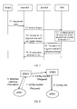
- FIG. 6 is a flowchart of interface information synchronization method in an embodiment of the present invention. As shown in FIG. 6 , the interface information synchronization method of the source RAN node includes at least the following steps:
- the target RAN node after receiving the message (such as Config Request message), the target RAN node sends a new configuration information table (such as Config Info message) to the source RAN node.
- a new configuration information table such as Config Info message
- FIG. 7 is a flowchart of interface information synchronization method in another embodiment of the present invention. As shown in FIG. 7 , the interface information synchronization method of the source RAN node includes at least the following steps:
- the process of sending the information about the S 1 interface and/or the X2 interface to the neighboring RAN node includes the following steps:
- the EMS of the RAN node sends a message that carries the modified S1 and/or X2 interface information to the EMS that governs the neighboring RAN node.
- FIG. 8 is a flowchart of interface information synchronization method in another embodiment of the present invention.
- the change may be notified to the neighboring RAN node Network Management System (NMS) through a message, and the neighboring RAN node NMS notifies the change to the neighboring RAN node.
- NMS Network Management System
- a Config Modified message is sent to RAN node 1.
- RAN node 1 updates the stored S1 and X2 interface configuration table. The process proceeds to step 804.
- the information about the S1 interface between RAN node 1 and the core network node and/or the information about the X2 interface between RAN node 1 and the neighboring RAN node are sent to RAN node 2 through an EMS, as detailed below:
- FIG. 9 shows a structure of a radio network in an embodiment of the present invention.
- the radio network includes a core network node 710 and neighboring RAN nodes 720, 730, and 740.
- the RAN node 720 includes:
- the neighboring RAN node 730 includes:
- the judging unit 721 in the radio network judges whether the interface information of the RAN node needs to be updated. If the interface information needs to be updated, the RAN node notifies the latest S1 and/or X2 interface information to the neighboring RAN node 730 automatically. Therefore, the neighboring RAN nodes 730 and 740 keep aware of the latest X2 interface information and S 1 interface information of the neighboring RAN nodes 730 and 740. The interface is determined according to the latest S1 and/or X2 interface information so that the handover operation is performed quickly.
- the judging unit 721 is adapted to:
- the RAN node 720 includes:
- the RAN node 720 may further receive the interface information of the neighboring RAN node 730.
- the interface information includes: the information about the S1 interface between the neighboring RAN node 730 and the core network node, and/or the information about the X2 interface between the neighboring RAN node 730 and the RAN node 720.
- the RAN node 720 may further include a handover selecting unit (not illustrated in the figure), which is adapted to: search for the interface information; if finding the information about the X2 interface between the RAN node 720 and the neighboring RAN node 730 as well as the information about the S 1 interface between the serving core network node 710 of the RAN node 720 and the neighboring RAN node 730 which serves as a target node, select the X2 interface for initiating a handover operation; otherwise, select the S 1 interface for initiating a handover operation.
- a handover selecting unit (not illustrated in the figure), which is adapted to: search for the interface information; if finding the information about the X2 interface between the RAN node 720 and the neighboring RAN node 730 as well as the information about the S 1 interface between the serving core network node 710 of the RAN node 720 and the neighboring RAN node 730 which serves as a target node, select the X2 interface for initiating a
- the RAN node 730 includes:
- a RAN node 830 is disclosed in the third embodiment of the RAN node of the present invention.
- the RAN node 830 includes:
- the first, second, and third embodiments of the RAN node described above may be applied to the embodiments of the interface information synchronization method and the communication handover method, and can support the X2 and S1 interface information synchronization function and the communication handover function performed according to the X2 and S 1 interface information.
- the high costs and low efficiency caused by static configuration and manual modification of the RAN node interface information in the prior art are overcome, the trouble of judging whether the X2 interface is available for handover in the prior art is avoided, the handover speed is improved, and the system load is reduced.
- the source RAN node performs handover through the S1 interface if the interface handover table indicates that the handover can be performed through an S 1 interface to the target RAN node, or else performs handover through the X2 interface.
- the source RAN node performs handover through an X2 interface if the interface information indicates that an X2 interface exists between the source RAN node and the target RAN node and/or an S1 interface exists between the serving core network node of the source RAN node and the target RAN node, or else performs handover through an S1 interface.
- the storage medium mentioned above may be a ROM/RAM, magnetic disk, compact disk, and so on.
- the judging unit 721, the sending unit 722, and the handover selecting unit 733 in the first embodiment of the RAN node of the present invention may be integrated in one computation processing module; and the receiving unit 731, the processing unit 732, and the handover selecting unit 733 of the RAN node in the second embodiment of the present invention may be integrated in one processing module, or even all units in an embodiment of the present invention may be integrated in one processing module.
- the judging unit 721, the sending unit 722, and the handover selecting unit 733 in the first embodiment of the RAN node of the present invention may be hardware or software function modules, and it is the same with the receiving unit 731, the processing unit 732, and the handover selecting unit 733 of the RAN node in the second embodiment.
- the combination of the foregoing units may be sold or applied as an independent product, or stored in a computer-readable storage medium.
Landscapes
- Engineering & Computer Science (AREA)
- Computer Networks & Wireless Communication (AREA)
- Signal Processing (AREA)
- Mobile Radio Communication Systems (AREA)
- Synchronisation In Digital Transmission Systems (AREA)
Abstract
Description
- The present invention relates to the communication field, and in particular, to an interface information synchronization method, a communication handover method, a radio network, and a Radio Access Network (RAN) node.
- The Long Term Evolution/System Architecture Evolution (LTE/SAE) network system project is the biggest new technology development project launched by the 3rd Generation Partnership Project (3GPP) in recent years. The core of such a technology is Orthogonal Frequency Division Multiplexing (OFDM)/Frequency Division Multiple Access (FDMA), and therefore, such a technology has some 4th Generation (4G) features and is regarded as a quasi-4G technology.
FIG. 1 shows an architecture of an LTE/SAE in the prior art. The LTE/SAE network system includes an evolved Node B (eNB, an evolved RAN node) and the Mobility Management Entity/Serving System Architecture Evolution Gateway (MME/SGW) that manages the RAN nodes. The interface between the MME/SGW and the eNB is an S1 interface, and the interface between eNBs is an X2 interface. - In the current LTE, the communication handover process falls into two types: handover from a source eNB to a target eNB through an X2 interface; and handover from a source eNB to a target eNB through an
S 1 interface, as described below: - Handover through an X2 interface: In the handover process, the source eNB and the target eNB are governed by the same MME; the MME is unchanged; and the source eNB sends a Handover Request message to the target eNB through an X2 interface to perform handover. In this case, the handover process involves no MME, and is known as handover through an X2 interface. The handover performed through an X2 interface involves use of an S1 interface.
- Handover through an
S 1 interface: When the MME involved in the handover process changes, namely, when the source eNB and the target eNB are not governed by the same MME, the source eNB needs to send a Handover Request message through anS 1 interface, which is known as handover through anS 1 interface. - When an eNB initiates handover, as regards how to select either of the foregoing handover methods, the prior art puts forward the following eNB handover selection method:
- A. If no X2 interface exists, the handover is performed through the
S 1 interface. - B. If the handover configured in the source eNB to the neighboring target eNB is performed through an
S 1 interface, the handover is performed through theS 1 interface.
In this method, a static table is reserved in the source eNB first, and a decision is made about whether to perform handover through an S1 interface or an X2 interface according to the interface connection information related to the neighboring eNB and recorded in the static table. However, the prior art describes neither the structure of such a static table nor information about how to use the static table to perform communication handover. - C. If a rejection message is received from the target eNB during the X2 interface handover, it indicates that the handover cannot be performed through an X2 interface, and therefore, the handover is performed through an S1 interface.
- In this method, the Handover Request is sent through an X2 interface so long as an X2 interface connection exists. If the target eNB finds it impossible to perform handover through an X2 interface, for example, if it is determined that the same MME connection is lacking, the target eNB sends a handover failure message to the source eNB. The handover failure message carries the corresponding cause value, and instructs the source eNB to send a Handover Require message to the MME again through an
S 1 interface.
In the process of developing the present invention, the inventor finds at least the following defects in the prior art: - (1) For solution B, the source eNB needs to know the static configuration of the relevant interface of the neighboring eNB. Data needs to change with the change of the configuration of the neighboring eNB. Manual modification of the static configuration consumes much time and effort, and is vulnerable to errors. Besides, the prior art describes neither the structure of the static table nor the information about how to use the static table to perform communication handover.
- (2) In solution C, for the handover which can be performed only through the
S 1 interface, sending a Handover Request first through the X2 interface is necessary, which wastes resources and increases delay. According to the X2 interface handover process in the prior art, the target eNB can set up air interface resources upon receiving a Handover Request. However, if solution C is applied, the target eNB needs to judge whether X2 interface handover is practicable after receiving a Handover Request, thus increasing futile operations for the X2 interface-enabled handover processes. - The present invention discloses an interface information synchronization method, a communication handover method, a radio network, and a RAN node, thus improving the efficiency of communication handover.
- An interface information synchronization method is disclosed in an embodiment of the present invention. The method includes: judging whether a condition for initiating interface information update is fulfilled; sending information about an
S 1 interface between a RAN node and a core network node, and/or information about an X2 interface between the RAN node and a neighboring RAN node to the neighboring RAN node if the condition for initiating interface information update is fulfilled.
A communication handover method is disclosed in an embodiment of the present invention. The method includes: - reading, by a source RAN node, a stored interface handover entries when handover occurs, where the interface handover entries include information indicating whether the handover can be performed to the target RAN node through an S1 interface, and the interface handover entries are obtained according to the
S 1 and/or an X2 interface information; and - performing the handover through the S1 interface if the interface handover entries include the information that the handover can be performed to the target RAN node through the
S 1 interface; otherwise, performing the handover through the X2 interface. - reading, by a source RAN node, interface information when handover occurs, where the interface information includes information about whether an X2 interface exists between the source RAN node and a target RAN node and/or information about whether an S1 interface exists between a serving core network of the source RAN node and the RAN node; and
- performing handover through the X2 interface if the interface information indicates that the X2 interface exists between the source RAN node and the target RAN node and/or the S1 interface exists between the serving core network node of the source RAN node and the target RAN node; otherwise, performing handover through the
S 1 interface. - The first RAN node includes:
- a judging unit, adapted to judge whether a condition for initiating interface information update is fulfilled; and
- a sending unit, adapted to send information about an X2 interface between the first RAN node and the second RAN node and/or information about an S1 interface between the first RAN node and the serving core network node to the second RAN node if the condition for initiating interface information update is fulfilled.
- The second RAN node includes:
- a receiving unit, adapted to receive the
S 1 and/or X2 interface information; - a handover selecting unit, adapted to search for the interface information; if finding information about the X2 interface between the first RAN node and the second RAN node and determining that an S1 interface connection exists between the serving core network node and the first RAN node according to the S1 interface information, initiate a handover operation to the first RAN node through the X2 interface; otherwise, initiate the handover operation to the first RAN node through the S1 interface.
- a judging unit, adapted to judge whether a condition for initiating interface information update is fulfilled; and
- a sending unit, adapted to send information about an X2 interface between the RAN node and a neighboring RAN node and/or information about an S1 interface between the RAN node and a core network node to the neighboring RAN node if the judging unit determines that the condition for initiating interface information update is fulfilled.
- a receiving unit, adapted to receive
S 1 and/or X2 interface information from a neighboring RAN node; - a processing unit, adapted to configure or update the interface information of the neighboring RAN node after the receiving unit receives the S1 and/or X2 interface information; and
- a handover selecting unit, adapted to search the processing unit for the interface information; if finding the information about the X2 interface between the RAN node and the neighboring RAN node as well as the information about the S1 interface between a serving core network node of the RAN node and the neighboring RAN node, select the X2 interface for initiating a handover operation to the neighboring RAN node; otherwise, select the S1 interface for initiating the handover operation to the neighboring RAN node.
- a receiving unit, adapted to receive S1 and/or X1 interface information from a neighboring RAN node;
- an interface information generating unit, adapted to judge whether a core network node of the RAN node serving as a source node is the same as a core network node of the neighboring RAN node serving as a target node according to the interface information of the RAN node and the S1 and/or X1 interface information received by the receiving unit; and generate handover information indicative of handing over to the target RAN node through an S1 interface if the core network node of the RAN node serving as the source node is not same as the core network node of the neighboring RAN node serving as the target node; and
- a handover selecting unit, adapted to search for the handover information generated by the interface information generating unit during the handover; if finding the information about the handover performed through the S1 interface to the target RAN node, select the S2 interface for initiating a handover operation to the neighboring RAN node; otherwise, select the X2 interface for initiating a handover operation to the neighboring RAN node.
-
-
FIG. 1 shows a structure of an LTE/SAE network in the prior art; -
FIG. 2 is a flowchart of a communication handover method in an embodiment of the present invention; -
FIG. 3 shows X2 and S1 interface connections in an LTE/SAE network; -
FIG. 4 is a flowchart of interface information synchronization method in another embodiment of the present invention; -
FIG. 5 is a flowchart of a communication handover method in an embodiment of the present invention; -
FIG. 6 is a signaling flowchart of interface information synchronization method in another embodiment of the present invention; -
FIG. 7 is a signaling flowchart of interface information synchronization method in another embodiment of the present invention; -
FIG. 8 is a signaling flowchart of interface information synchronization method in another embodiment of the present invention; -
FIG. 9 shows a structure of a radio network in an embodiment of the present invention; and -
FIG. 10 shows a structure of a RAN node in an embodiment of the present invention. - A communication handover method is disclosed in an embodiment of the present invention. The method includes:
- A RAN node stores the information about the X2 interface between the RAN node and a neighboring RAN node, and/or the information about the
S 1 interface between the neighboring RAN node and a core network node. The information about the X2 interface or theS 1 interface may be interface configuration information and/or interface state information. The configuration information and/or state information constitute a configuration table (S1 or X2 interface configuration table of the RAN node). - If the S1 or X2 interface configuration/state of the RAN node changes, the RAN node sends the changed
S 1 or X2 interface configuration/state information to the neighboring RAN node, notifying the neighboring RAN node to modify the corresponding S1 or X2 interface configuration table. - Therefore, RAN nodes in the communication network have the latest S1 or X2 interface configuration table. When handover occurs, the source RAN node searches for the configuration information of the target RAN node in the S1 or X2 interface configuration table. A procedure is used to perform handover from a source RAN node to a target RAN node using X2 interface when S1 interface exists between the target RAN node and a serving core network node of the source RAN node. Otherwise the S1-based handover procedure is used.
- A communication handover method is disclosed in an embodiment of the present invention. The method includes:
- The
S 1 interface information between the RAN node and the core network node is transmitted to the neighboring RAN node through an X2 interface. The neighboring RAN node generates an S1 interface handover table according to theS 1 interface information of the neighboring RAN node itself and the receivedS 1 interface information, where theS 1 interface handover table indicates whether the handover is necessarily performed through the S1 interface. The S1 interface handover table is stored dynamically. Whenever theS 1 interface configuration/state of the neighboring RAN node changes, the change is notified to the RAN node through the X2 interface. The RAN node modifies theS 1 interface handover table according to theS 1 interface information. When handover occurs, the source RAN node searches theS 1 interface handover table for the target RAN node. If finding the target RAN node, the source RAN node selects theS 1 interface for handover; otherwise, the source RAN node selects the X2 interface for handover. Through the method disclosed in the embodiment of the present invention, the RAN nodes may exchange S1 interface information and/or X2 interface information automatically through automatic configuration of the network. More specifically, the interface information for exchanging is: bothS 1 interface information and X2 interface information; onlyS 1 interface information; or only X2 interface information. - The RAN node may be an eNB, and the core network node may be an MME.
- An interface information synchronization method is disclosed in an embodiment of the present invention. The method includes:
- judging whether a condition for initiating interface information update is fulfilled;
- sending information about the S1 interface between the RAN node and the core network node, and/or information about the X2 interface between the RAN node and the neighboring RAN node to the neighboring RAN node if the condition for initiating interface information update is fulfilled;
- receiving the
S 1 and/or X2 interface information; and - configuring or updating the interface information of the neighboring RAN node according to the received
S 1 and/or X2 interface information. - In the embodiment described above, the S1 and/or X2 interface information of the RAN node is sent to the neighboring RAN node when the condition is fulfilled. When the neighboring RAN node hands over to the RAN node, the neighboring RAN node can determine whether an S1 interface exists between the neighboring RAN node itself and the core network according to its
own S 1 interface information and the receivedS 1 interface information, and can accurately determine the interface available for handover according to the received X2 interface information. Therefore, the proper interface is selected accurately and quickly, the trouble of judging whether the X2 interface is available for handover in the case of unawareness of the interface information in the prior art is avoided, the handover efficiency is improved, and the system load is reduced. - In the communication handover method disclosed in the embodiment of the present invention, when handover occurs, the source RAN node reads the stored interface handover table (the interface handover table includes the information indicating whether the handover can be performed through an
S 1 interface to the target RAN node). The source RAN node performs handover through theS 1 interface if the interface handover table indicates that the handover can be performed through the S1 interface to the target RAN node; otherwise, the source RAN node performs handover through the X2 interface. Therefore, the proper interface is selected accurately and quickly. The trouble of judging whether the X2 interface is available for handover in the case of unawareness of the interface information in the prior art is avoided, the handover efficiency is improved, and the system load is reduced. - In the communication handover method disclosed in the embodiment of the present invention, the source RAN node reads interface information when handover occurs, the interface information includes the information about whether an X2 interface exists between the source RAN node and the target RAN node and/or the information about whether an
S 1 interface exists between the serving core network node of the source RAN node and the target RAN node. The source RAN node performs handover through the X2 interface if the interface information indicates that an X2 interface exists between the source RAN node and the target RAN node and/or anS 1 interface exists between the serving core network node of the source RAN node and the target RAN node; or else performs handover through the S1 interface. Therefore, the proper interface is selected accurately and quickly. The trouble of judging whether the X2 interface is available for handover in the case of unawareness of the interface information in the prior art is avoided, the handover efficiency is improved, and the system load is reduced. - In the communication handover method disclosed in the embodiment of the present invention, the interface information or the interface handover table is read when handover occurs, a proper interface is selected for handover according to the interface handover requirement recorded in the interface handover table or according to the interface which is determined as available for handover in view of the interface information. The judging mode is: A Handover Request is sent through the X2 interface if the interface information includes the information about the X2 interface exists between the source RAN node and the target RAN node and the information about the S1 interface exists between the serving core network node of the source RAN node and the target RAN node; otherwise, the Handover Request is sent through an S1 interface. Therefore, the proper interface is selected accurately and quickly. The trouble of judging whether the X2 interface is available for handover in the case of unawareness of the interface information in the prior art is avoided, the handover efficiency is improved, and the system load is reduced.
- In order to make the technical solution, objectives and merits of the present invention clearer, the communication handover method under the present invention is detailed below by reference to
FIG. 2 . -
FIG. 2 is a flowchart of a communication handover method in an embodiment of the present invention. The process includes at least the following steps: - Step 201: The source RAN node reads
S 1 and X2 interface information when handover occurs, the interface information includes the information about whether an X2 interface exists between the source RAN node and the target RAN node and/or the information about whether an S1 interface exists between the serving core network node of the source RAN node and the target RAN node. - As described above, the
S 1 and the X2 interface information may exist in the form ofS 1 and X2 interface configuration table, and may be stored on the source RAN node. Taking the LTE/SAE network shown inFIG. 3 as an example,RAN node 1 is adjacent to RAN nodes 2 and 3 in the network, and an X2 interface exists between them. - Table 1 is an exemplary structure of an
S 1 or X2 interface configuration table in the network. For example, inFIG. 3 ,RAN node 1 is adjacent to RAN nodes 2 and 3, and an X2 interface exists between them.RAN node 1 may store the following table:Table 1: S 1 or X2 interface configuration table ofRAN node 1RAN node core network node 1core network node 2 core network node 3 RAN node 2 0 1 1 RAN node 3 0 0 1 - The first column of the table is the information about the neighboring RAN node. The first column includes RAN node 2 and RAN node 3. An X2 interface exists between
RAN node 1 and RAN nodes 2 and 3. If the column has no name of a RAN node, it indicates that no X2 interface exists betweenRAN node 1 and the RAN node. - The first row of the table indicates the relevant core network nodes, and the content below the second row indicates whether an
S 1 interface exists between each neighboring RAN node and the relevant core network node. "1" indicates that an S1 interface exists between a RAN node and the relevant core network node; and "0" indicates that noS 1 interface exists between them. The foregoing table reveals that: An S1 interface exists between RAN node 2 and core network nodes 2 and 3, but no S1 interface exists between RAN node 2 andcore network node 1; an S1 interface exists between RAN node 3 and core network node 3, but no S1 interface exists between RAN node 3 andcore network node 1 or 2. - In this case, when the source RAN node knows existence of an S1 interface between the source RAN node and the relevant core network node, according to the second row and the content below the second row, the source RAN node may infer whether an
S 1 interface exists between the serving core network of the source RAN node and other neighboring RAN nodes. For example, if RAN node 2 and the serving core network node 2 ofRAN node 1 correspond to the position "1" in the table butRAN node 1 already knows that anS 1 interface exists betweenRAN node 1 and core network node 2, it is inferred that an S1 interface exists betweenRAN node 1 and the serving core network node 2 of RAN node 2. - Obviously, the first column of the table indicates whether an X2 interface exists between the source RAN node and other neighboring RAN nodes. The second row of the table indicates whether an S1 interface connection exists between the neighboring RAN node and the core network node. The source RAN node may infer whether an S1 interface exists between the serving core network node of the source RAN node and the neighboring RAN node according to the
S 1 interface information of the source RAN node and theS 1 interface information below the second row in the table. Likewise, other neighboring RAN nodes also store similar configuration tables for communication handover. Table 2 and Table 3 are examples:Table 2: S1 or X2 interface configuration table of RAN node 2 RAN node Core network node 1Core network node 2 Core network node 3 RAN node 11 1 0 Table 3: S1 or X2 interface configuration table of RAN node 3 RAN node core network node 1core network node 2 core network node 3 RAN node 11 1 0 - Nevertheless, the RAN node may also add its own S1 interface information into the first row of the foregoing configuration table. The second row and the content below it are the information about the neighboring RAN node, as shown in Table 4:
Table 4: S1 or X2 interface configuration table of RAN node 1RAN node Core network node 1Core network node 2 Core network node 3 RAN node 11 1 0 RAN node 2 0 1 1 RAN node 3 0 0 1 - In this way, according to the information in Table 4, when
RAN node 1 serves as a source RAN node, it is easy to determine whether an S1 interface exists between the source RAN node and a core network node, and whether an S1 interface exists between another neighboring RAN node and the core network node. - When handover needs to occur on the source RAN node, the source RAN node reads the S1 and X2 interface configuration table stored locally first, and then performs the following steps:
- Step 202: If the interface configuration table includes the information about the X2 interface exists between the source RAN node and the target RAN node and the information about the S1 interface exists between the serving core network node of the source RAN node and the target RAN node, the source RAN node sends a Handover Request to the target RAN node through the X2 interface; otherwise, the source RAN node sends a Handover Request to the target RAN node through the S1 interface.
- In practice, the details of this step are as follows:
- A. If no target RAN node is found in the first column of the interface configuration table, it indicates that no X2 interface exists between the source RAN node and the target RAN node, and the source RAN node sends a Handover Request message of the
S 1 interface directly. If a target RAN node is found, it indicates that an X2 interface exists between the source RAN node and the target neighboring RAN node, and the process proceeds to step C. - C. The second row and the rows below it in the interface configuration table are searched for the "target RAN node" row and the "serving core network node of the source RAN node" row to check the value at the intersection between such a row and the column. If the value is "0", it indicates that no
S 1 interface exists between the serving core network node of the source RAN node and the target RAN node, and the source RAN node sends the Handover Request message of theS 1 interface directly. If the value is "1", it indicates that anS 1 interface exists between the serving core network node of the source RAN node and the target RAN node, and the process proceeds to step E. - E. Through an X2 interface, a Handover Request is sent to the target RAN node.
- As revealed in the foregoing description, the RAN node in the radio network judges whether an
S 1 interface exists between the RAN node and the core network according to theS 1 interface information of the RAN node and the receivedS 1 interface information, and can select a proper interface accurately and quickly according to the received X2 interface information. Therefore, the trouble of judging whether the X2 interface is available for handover after receiving a Handover Request in the prior art is avoided, the handover speed is improved, and the system load is reduced. - If an S1 interface exists between the serving core network node of the source RAN node and the target RAN node, and if an X2 link exists between the source RAN node and the target RAN node but the X2 link disconnected, then the handover fails if the Handover Request is sent through the X2 interface directly. Therefore, this step is added to judge the X2 interface link state first. If the X2 interface link state is abnormal, the Handover Request is sent through an
S 1 interface, thus improving the handover success ratio. - For that purpose, a state value is added on the basis of the S1 or X2 interface configuration table to indicate whether the X2 or
S 1 interface links are normal. Specifically, a parameter may be added to indicate whether the link is available or existent. Table 5 gives an example:Table 5: S1 or X2 interface configuration table on RAN node 1RAN node core network node 1core network node 2 core network node 3 X2 RAN node 2 0 1 2 1 RAN node 3 0 0 1 2 - In Table 5, the "X2" column is additional, the "0" value indicates that no link exists, "1" indicates normal, and "2" indicates link failure. The parameters in Table 5 mean that: The X2 link between
RAN node 1 and RAN node 2 is normal; the X2 link betweenRAN node 1 and RAN node 3 is unavailable; no S1 connection exists between RAN node 2 andcore network node 1, the S1 connection between RAN node 2 and core network node 2 is normal, and the S1 connection between RAN node 2 and core network node 3 is unavailable; and the X2 link betweenRAN node 1 and RAN node 3 is unavailable. - In other embodiments, the "X2" column may exist in another table. The "X2" column is optional, and is useful in
step 201. - When the S1 and X2 interface configuration table in Table 5 is in use, if a target RAN node is found in the first column of the S1 and X2 interface configuration table in step A, step B may be performed before step C:
- B. The first column of the S1 and X2 interface configuration table is searched for the target RAN node. If a target RAN node is found, the value in the "X2" column of the S1 and X2 interface configuration table is looked up. If the X2 link is found to be unavailable, a Handover Request message is sent through the
S 1 interface; otherwise, the process proceeds to step C and then to step D. - D. It is judged whether S1 connection state of the target RAN node is normal. If the S1 connection state of the target RAN node is normal, a Handover Request is sent through the X2 interface to perform handover; otherwise, a Handover Request message is sent through the S1 interface to perform handover.
- For example, when
source RAN node 1 needs to hand over to target RAN node 2,source RAN node 1 searches Table 5. If the X2 state value is "1", it indicates that the X2 link is normal. Afterward, the state of the core network node connected with RAN node 2 is checked. If the state value of core network node 2 is "1", it indicates that theS 1 link is normal, and the handover is performed through the X2 interface. - In other embodiments, an additional option may be set in the
S 1 or X2 interface configuration table to indicate whether the handover needs to be performed through theS 1 interface or the X2 interface. If theS 1 and X2 interface configuration table includes the information about the X2 interface between the source RAN node and the target RAN node and the information about the S1 interface between the serving core network node of the source RAN node and the target RAN node, information is set to indicate that the handover needs to be performed through the X2 interface; otherwise, information is set to indicate that the handover needs to be performed through theS 1 interface. - Alternatively, a
simpler S 1 interface handover table is generated dynamically on the basis of theS 1 or X2 interface configuration table. TheS 1 interface handover table indicates whether the handover to the target RAN node needs to be performed through theS 1 interface. TheS 1 interface handover table directly decides whether theS 1 interface handover process or the X2 interface handover process applies. - The
S 1 interface handover table falls into the following two types: - (1) The S1 interface handover table includes MME and S1 interface options.
- In the S1 or X2 interface configuration table, if the
S 1 interface link of the serving MME of the source RAN node in Table 1 or Table 5 is already configured, or if theS 1 interface is in the available state, information needs to be set in theS 1 interface handover table to indicate that the handover to the target RAN node needs to be performed through the S1 interface, as detailed in Table 6:Table 6: Interface handover table 1 Core network node RAN node 2 RAN node 3 MME1 1 1 MME2 0 1 - In Table 6, if an
S 1 interface connection exists between the serving core network node of the source RAN node and the target RAN node, the value of theS 1 handover option in the interface handover table is 0, indicating that the handover needs to be performed through the X2 interface instead of the S1 interface; otherwise, the value is 1, indicating that the handover needs to be performed through the S1 interface. The S1 interface link state may be considered at the same time. For example, when theS 1 interface link state is normal, the value of the option is 0; otherwise, the value of the option is 1. - For the purpose of handover, this table may be searched for the value corresponding to the target RAN node and the serving core network node of the source RAN node, and the handover selection is made according to such a value directly, without the need of searching the S1 or X1 interface configuration table.
- Table 6 may be generated by reference to Table 5. After receiving the X2 or
S 1 interface information of the neighboring RAN node, the source RAN node generates an X2 orS 1 interface configuration table described above, and then generates anS 1 interface handover table (as shown in Table 6) according to whether anS 1 interface connection exists between the source RAN node and the serving core network node of the source RAN node. That is, if the state indicated in the "core network node" column in Table 5 is "available", the handover needs to be performed through the X2 interface; otherwise, the handover needs to be performed through theS 1 interface. - (2) The interface handover table includes only the
S 1 interface option. - This solution is similar to solution (1), but differs in that: The interface handover table includes only the
S 1 interface option of different core network nodes between two RAN nodes, and is simpler. The principles are as follows: - It is assumed that all MMEs connected to the same RAN node are in the same MME pool, and different MME pools are never connected to the same RAN node. Although an X2 interface exists between two RAN nodes, they are connected to two MME pools, and the handover between them needs to be performed through the S1 interface. An interface handover table may be configured, and such RAN nodes are put into the table. The RAN node in such an interface handover table needs to hand over through an
S 1 interface. - The interface handover table is set in the following way:
- I. The
S 1 interface information of the target RAN node needs to be obtained first. Through an X2 interface, the target RAN node sends the S1 interface information of the S1 interface between the target RAN node and one MME/multiple MMEs/all MMEs to the source RAN node. - II. According to the
S 1 interface information of the target RAN node and theS 1 interface information of the source RAN node, judging whether both the source RAN node and the target RAN node are connected to the same core network node through anS 1 interface. - If the source RAN node and the target RAN node are not connected to the same core network node through an S1 interface, it is only necessary to set information in the interface handover table to indicate that the handover to the target RAN node needs to be performed through an S1 interface.
- After receiving the
S 1 interface information, the source RAN node compares the receivedS 1 interface information with itsown S 1 interface information. If one MME/multiple MMEs/all MMEs are the same, it indicates that the source RAN node and the target RAN node are in the same MME pool; otherwise, it indicates that the source RAN node and the target RAN node are not in the same MME pool. The RAN nodes not in the same MME pool are put into the interface handover table. TheS 1 information includes configuration information, and optionally, link state information. As shown in Table 7, RAN node 2 and the source RAN node are not in the same MME pool:Table 7: Interface handover table 2 Target RAN node State eNB2 1 - The communication handover method under the present invention is detailed below by reference to
FIG. 4 . As shown inFIG. 4 , the communication handover process includes at least the following steps: - Step 401: The source RAN node searches the interface handover table.
- Step 402:
- A. If the interface handover table includes a target RAN node or the link state is normal, the handover is performed through the S1 interface.
- B. Otherwise, an attempt is made to hand over through an X2 interface; or, if the link state is abnormal, handover failure is fed back directly.
- If more state information exists in Table 7, and if the state information indicates link normal, the handover is performed through the
S 1 interface. This state information is optional. - If the S1 or X2 interface of the RAN node changes, a notification needs to be sent to the neighboring RAN node to let the neighboring RAN node update the S1 or X2 interface configuration table. Therefore, an interface information synchronization method in the second embodiment of the present invention is put forward. As shown in
FIG. 5 , the method includes the following steps: - Step 501: A judgment is made about whether a condition for initiating interface information update is fulfilled.
- In this embodiment, a judgment is made about whether the configuration and/or the state of the S1 interface and/or the X2 interface of the RAN node has changed.
- Step 502: If the condition for initiating interface information update is fulfilled, the information about the S1 interface between the RAN node and the core network node, and/or the information about the X2 interface between the RAN node and the neighboring RAN node, is sent to the neighboring RAN node.
- When the configuration and/or the state of the S1 interface and/or the X2 interface of the RAN node changes (for example, the RAN node is connected to another core network node, or the
S 1 interface configuration changes, or the address of the X2 interface to the neighboring RAN node changes, or the configuration of both the S1 interface and the X2 interface changes), a message is sent to the neighboring RAN node through the X2 interface, where the message carries the information about theS 1 interface and/or the X2 interface of the RAN node. - The information about the
S 1 interface and/or the X2 interface of the RAN node may be a special signaling (such as a Config Info message) sent to neighboringRAN node 1, or may be added into another automatic configuration message sent to neighboringRAN node 1. - The information about the S1 interface and/or the X2 interface of the RAN node includes: information about the X2 interface between the RAN node and the neighboring RAN node, and/or information about the S1 interface between the RAN node and the core network node. The information about the
S 1 interface and/or the X2 interface of the RAN node may include the information indicating whether theS 1 interface and/or the X2 interface between the RAN node and the neighboring RAN node is available, for example, the parameter indicative of the state in theS 1 and X2 interface configuration table in Table 5. - Step 503: The neighboring RAN node receives the S1 and/or X2 interface information.
- Step 504: The neighboring RAN node configures or updates the interface information of the neighboring RAN node according to the received
S 1 and/or X2 interface information. - In this step, after the neighboring RAN node receives the
S 1 and/or X2 interface information, the neighboring RAN node configures the interface information if no old interface information exists; or updates the interface information if old interface information already exists. - The foregoing description reveals that: The RAN node in the radio network notifies the latest S1 and/or X2 interface information to the neighboring RAN node automatically when a certain condition is fulfilled. Therefore, the neighboring RAN node keeps aware of the latest X2 interface information and the S1 interface information of the neighboring RAN node. The interface is determined according to the
latest S 1 and/or X2 interface information so that the handover operation is performed quickly. The high costs and low efficiency caused by static configuration and manual modification of the RAN node interface information in the prior art are overcome, the trouble of judging whether the X2 interface is available for handover in the prior art is avoided, the handover speed is improved, and the system load is reduced. - Besides, the RAN node can also receives the interface information of the neighboring RAN node. The interface information includes: the information about the S1 interface between the neighboring RAN node and the core network node, and/or the information about the X2 interface between the neighboring RAN node and the RAN node.
- Therefore, the RAN node not only sends interface information to other RAN nodes, but also receives interface information from other RAN nodes as a basis for selecting the interface for handover. If the present invention is applied to all the RAN nodes in the radio network, the RAN nodes exchange the
latest S 1 and/or X2 interface information, and any RAN node knows whether to use the X2 interface or theS 1 interface for handover to the target RAN node, thus improving the handover efficiency, avoiding handover failure, and avoiding the interface test operation. - Meanwhile, with the
S 1 and/or X2 link state being known, the selection of the handover request is more accurate and the handover success ratio is higher. - It is worthy of attention that when the S1 or S2 configuration of the RAN node changes, all neighboring RAN nodes can be notified through the X2 interface message anytime. After the interface information of the neighboring RAN node is configured or updated, the following operations are performed:
- The S1 interface handover table is obtained through calculation according to the interface information of the neighboring RAN node. The
S 1 interface handover table includes the information about selecting anS 1 or X2 interface for communication handover. In this way, the interface for handover is determined more quickly, and the speed of the handover operation is improved. - In the interface information synchronization method provided in the embodiment of the present invention, the judgment about whether the condition of initiating interface information update is fulfilled in
step 501 may be A, B, C, D, E, or F described below: - A. A judgment is made about whether the timer of the S1 and/or X2 interface information of the RAN node expires.
- All the RAN nodes exchange information with each other periodically. For example, a timer is set on the
S 1 and/or X2 interface information. Moreover, before the interface information is sent, a judgment may be made about whether theS 1 and/or X2 interface information or the link state of the RAN node changes; if the interface information or the link state changes, the neighboring RAN node is notified through a message; otherwise, the neighboring RAN node is not notified. Alternatively, no judgment is made, and the interface information is sent upon expiry of the timer. B. A judgment is made about whether a message that the neighboring RAN node requests the S1 and/or X2 interface information is received. - The RAN node may request the latest S1 and X2 interface information periodically from the neighboring RAN node through the X2 interface. Upon expiry of the timer of the RAN node, the RAN node requests the X2 and
S 1 interface information from the neighboring RAN node. - C. A judgment is made about whether the X2 handover operation initiated by the RAN node to the neighboring RAN node fails. For ease of description, the foregoing two nodes are called "source RAN node" and "target RAN node" respectively in the handover process described below.
- If the source RAN node searches the S1 and X2 interface configuration table and decides to perform handover through an X2 interface, the target RAN node may find that its
own S 1 interface link is disconnected after sending a Handover Request message. In this case, the target RAN node sends a Handover Failure message to the source RAN node. TheS 1 and X2 interface configuration table may be sent together with the Handover Failure message; or the target RAN node gives a cause value, and the source RAN node requests thenew S 1 and X2 interface configuration table from the target RAN node. Alternatively, if theS 1 interface of the target RAN node is unavailable, the core network node sends configuration table information about theS 1 interface to the source RAN node. - When the handover operation fails, the
S 1 and X2 interface information may be sent in the following way in step 502: - The Handover Failure response returned to the source RAN node carries the
S 1 and/or X2 interface information of the target RAN node. - Alternatively, the Handover Failure response returned to the source RAN node carries the failure cause, and the source RAN node analyzes the cause value after receiving the failure cause. If the failure cause is radio resource allocation failure, it indicates that the handover fails. If the
S 1 interface of the target RAN node is not configured or is unavailable, the source RAN node sends a request message, which requires the target RAN node to send anS 1 and/or X2 interface information message. The target RAN node sends itsS 1 and/or X2 interface information to the source RAN node. - Alternatively, the Handover Failure response returned to the source RAN node carries the failure cause. After the source RAN node receives the failure cause, if the failure cause is lack of an
S 1 interface connection between the target RAN node and the core network node, the source RAN node requests theS 1 and X2 interface configuration information of the target RAN node from the core network node. If the target S1 interface configuration recovers to normal, the handover may be performed through the X2 interface, but the source RAN node is still unaware of it. The source RAN node sends anS 1 interface Handover Request to the MME first. After receiving the Handover Request, the MME finds that the MME of the target RAN node is the same as that of the source RAN node. Therefore, the MME may also trigger the source RAN node to modify the configuration information of the target RAN node, or notify the target RAN node to send the S1 interface configuration information to the source RAN node. After receiving theS 1 interface configuration information of the target RAN node, the source RAN node modifies the X2 and S1 configuration table. - If the source RAN node searches the
S 1 and X2 interface configuration table and decides to perform handover through an X2 interface, the target RAN node may find that itsown S 1 interface link is disconnected after sending a Handover Request message. In this case, the target RAN node sends a Handover Failure message to the source RAN node. The S1 and X2 interface configuration table may be sent together with the Handover Failure message; or the target RAN node gives a cause value, and the source RAN node requests thenew S 1 and X2 interface configuration table from the target RAN node. Alternatively, if theS 1 interface of the target RAN node is unavailable, the core network node sends configuration table information about theS 1 interface to the source RAN node.FIG. 6 is a flowchart of interface information synchronization method in an embodiment of the present invention. As shown inFIG. 6 , the interface information synchronization method of the source RAN node includes at least the following steps: - Step 601: The terminal submits a measurement report.
- Step 602: After the source RAN node receives the measurement report, if the source RAN node decides to hand over and an X2 interface connection exists, the source RAN node sends a Handover Request to the target RAN node through an X2 interface.
- Step 603: If the target RAN node finds that the
S 1 interface is disconnected or the radio resource allocation fails, namely, if the handover fails and the condition for initiating interface information update is fulfilled, the target RAN node returns a Handover Failure message to the source RAN node. In this case, the Handover Failure message may carry a failure cause value. If the handover fails because noS 1 interface is configured or theS 1 interface is unavailable, the Handover Failure message may carry anS 1 and X2 interface configuration table.
The cause value here may be: lack of configuring the S1 interface of the target RAN node,unavailable S 1 state, radio resource allocation failure, NAS error, transmission channel error, or protocol failure. - Step 604: After receiving the Handover Failure message, the source RAN node judges the failure cause according to the cause value. If the handover fails because no
S 1 interface is configured or theS 1 interface is unavailable, and if the Handover Failure message carries a configuration table, the source RAN node updates the S1 and X2 interface configuration table on the source RAN node directly according to the configuration table. Otherwise, the process proceeds to step 605 if the Handover Failure message carries no configuration table and indicates only the S1 configuration error, and if the cause value is that noS 1 interface is configured or theS 1 interface is unavailable. If the handover fails due to radio resource allocation failure, the process is ended. Step 605: Through an X2 interface, the source RAN node sends a message (such as Config Info Request message) to the target RAN node, requesting new X2 andS 1 interface information. - Step 606: The information about the S1 interface between the target RAN node and the core network node and/or the information about the X2 interface between the target RAN node and the source RAN node is sent to the source RAN node.
- In this step, after receiving the message (such as Config Request message), the target RAN node sends a new configuration information table (such as Config Info message) to the source RAN node.
-
FIG. 7 is a flowchart of interface information synchronization method in another embodiment of the present invention. As shown inFIG. 7 , the interface information synchronization method of the source RAN node includes at least the following steps: - Step 701: The terminal submits a measurement report.
- Step 702: After the source RAN node receives the measurement report, if the source RAN node decides to hand over, the source RAN node reads the
S 1 and X2 interface configuration table and then decides to initiate handover to the target RAN node through anS 1 interface. - Step 703: The MME receives the Handover Request and judges whether the condition for initiating interface information update is fulfilled. That is, the MME judges whether an
S 1 interface connection exists between the target RAN node and the core network node, and between the source RAN node and the core network node. If it is determined that target RAN node and the source RAN node are governed by the same MME, the source RAN node is notified to update the S1 configuration information of the target RAN node. The process proceeds to step 704 or step 704', in which the S1 and/or X2 interface information of the target RAN node is sent to the source RAN node. - Step 704: The MME sends the S1 interface information of the target RAN node to the source RAN node, where the
S 1 interface information may be sent in an independent message or carried in the Handover Response message in the handover process; or - Step 704': The MME sends a message to the target RAN node, thus initiating the target RAN node to send S1 interface information to the source RAN node, where the S1 interface information may be sent in an independent message or carried in the Handover Response message in the handover process.
- Step 705: The source RAN node modifies the X2 and S1 interface configuration table or the S1 interface handover table.
- D. A judgment is made about whether the RAN node is restarted.
- E. A judgment is made about whether the Element Manager System (EMS) of the RAN node has modified the interface information of the RAN node.
- In this case, the process of sending the information about the
S 1 interface and/or the X2 interface to the neighboring RAN node includes the following steps: - The EMS of the RAN node sends a message that carries the modified S1 and/or X2 interface information to the EMS that governs the neighboring RAN node.
-
FIG. 8 is a flowchart of interface information synchronization method in another embodiment of the present invention. As shown inFIG. 8 , when the configuration changes, the change may be notified to the neighboring RAN node Network Management System (NMS) through a message, and the neighboring RAN node NMS notifies the change to the neighboring RAN node. This method includes at least the following steps: - Step 801: A judgment is made about whether a condition for initiating interface information update is fulfilled.
- If the configuration table of
RAN node 1 is changed through modification of EMS1, a Config Modified message is sent toRAN node 1. After receiving the Config Modified message,RAN node 1 updates the stored S1 and X2 interface configuration table. The process proceeds to step 804. - Alternatively, if the configuration table of
RAN node 1 changes, the information about the S1 interface betweenRAN node 1 and the core network node and/or the information about the X2 interface betweenRAN node 1 and the neighboring RAN node are sent to RAN node 2 through an EMS, as detailed below: - Step 802: EMS1 is notified through a Config Request message.
- Step 803: After receiving the Config Request message, EMS1 modifies the corresponding configuration.
- Step 804:
EMS 1 sends a Config Request that carriesS 1 and/or X2 interface information to the neighboring EMS2. EMS2 modifies the corresponding configuration table according to the S1 and/or X2 interface information. - Step 805: EMS2 notifies RAN node 2 through a Config Info message that carries the S1 and/or X2 interface information.
- Step 806: RAN node 2 modifies the corresponding configuration table according to the S1 and/or X2 interface information.
- F. When
S 1 interface handover occurs and the core network node receives Handover Request message of the source RAN node, a judgment is made about whether the target RAN node and the source RAN node are connected to the same core network. If such is the case, theS 1 interface information of the target RAN node is sent to the source RAN node; or the target RAN node is triggered to send S1 interface information to the source RAN node. -
FIG. 9 shows a structure of a radio network in an embodiment of the present invention. As shown inFIG. 9 , the radio network includes acore network node 710 and neighboringRAN nodes RAN node 720 includes: - a judging
unit 721, adapted to judge whether a condition for initiating interface information update is fulfilled; and - a sending
unit 722, adapted to: send the information about the S1 interface between theRAN node 720 and thecore network node 710, and/or the information about the X2 interface between theRAN node 720 and the neighboringRAN node 730 to the neighboringRAN node 730 if the condition for initiating interface information update is fulfilled. - The neighboring
RAN node 730 includes: - a receiving
unit 731, adapted to receive theS 1 and/or X2 interface information; - a
processing unit 732, adapted to configure or update the interface information of the neighboringRAN node 730 according to the received S1 and/or X2 interface information; and - a
handover selecting unit 733, adapted to: search theprocessing unit 732 for the interface information; if finding information about the X2 interface between the two neighboring RAN nodes and determining that an S1 interface connection exists between the servingcore network node 710 of the source neighboringRAN node 720 and the neighboringRAN node 730 which serves as a target node according to theS 1 interface information, select the X2 interface to initiate a handover operation; otherwise, select theS 1 interface to initiate a handover operation. - The foregoing description reveals that: The judging
unit 721 in the radio network judges whether the interface information of the RAN node needs to be updated. If the interface information needs to be updated, the RAN node notifies the latest S1 and/or X2 interface information to the neighboringRAN node 730 automatically. Therefore, the neighboringRAN nodes S 1 interface information of the neighboringRAN nodes - The judging
unit 721 is adapted to: - judge whether the configuration and/or the state of the S1 interface and/or the X2 interface of the
RAN node 720 has changed; or - judge whether the timer of the S1 and/or X2 interface information of the
RAN node 720 expires; or - judge whether a message that the neighboring
RAN node 730 requests the S1 and/or X2 interface information is received; or - judge whether the X2 handover operation initiated by the neighboring
RAN node 730 to theRAN node 720 fails; or - judge whether the
RAN node 720 is restarted; or - judge whether the EMS of the
RAN node 720 has modified the interface information of theRAN node 720. - As shown in
FIG. 9 , a RAN node is disclosed in an embodiment of the present invention. TheRAN node 720 includes: - a judging
unit 721, adapted to judge whether a condition for initiating interface information update is fulfilled; and - a sending unit, adapted to: send the information about the S1 interface between the
RAN node 720 and the core network node, and/or the information about the X2 interface between theRAN node 720 and the neighboringRAN node 730 to the neighboringRAN node 730 if the condition for initiating interface information update is fulfilled. - The
RAN node 720 may further receive the interface information of the neighboringRAN node 730. The interface information includes: the information about the S1 interface between the neighboringRAN node 730 and the core network node, and/or the information about the X2 interface between the neighboringRAN node 730 and theRAN node 720. In this case, theRAN node 720 may further include a handover selecting unit (not illustrated in the figure), which is adapted to: search for the interface information; if finding the information about the X2 interface between theRAN node 720 and the neighboringRAN node 730 as well as the information about theS 1 interface between the servingcore network node 710 of theRAN node 720 and the neighboringRAN node 730 which serves as a target node, select the X2 interface for initiating a handover operation; otherwise, select theS 1 interface for initiating a handover operation. - As shown in
FIG. 10 , a RAN node is disclosed in another embodiment of the present invention. TheRAN node 730 includes: - a receiving
unit 731, adapted to receive theS 1 and/or X2 interface information from the neighboringRAN node 720; - a
processing unit 732, adapted to configure or update the interface information of the neighboringRAN node 720 according to the receivedS 1 and/or X2 interface information; and - a
handover selecting unit 733, adapted to: search theprocessing unit 732 for the interface information; if finding the information about the X2 interface between theRAN node 730 and the neighboringRAN node 720 as well as the information about theS 1 interface between the servingcore network node 710 of theRAN node 730 and the neighboringRAN node 720 which serves as a target node, select the X2 interface for initiating a handover operation; otherwise, select theS 1 interface for initiating a handover operation. - As shown in
FIG. 8 , aRAN node 830 is disclosed in the third embodiment of the RAN node of the present invention. TheRAN node 830 includes: - a receiving
unit 831, adapted to receive the S1 interface information from the neighboring RAN node; - an interface
information generating unit 832, adapted to: judge whether the same core network node exists between theRAN node 830 which serves as a source node and the neighboring RAN node which serves as a target node according to the S1 interface information of the interfaceinformation generating unit 832 and theS 1 interface information received by the receivingunit 831; and generate handover information indicative of handing over to the target RAN node through an S1 interface if the same core network node does not exist; and - a
handover selecting unit 833, adapted to: search for the handover information generated by the interfaceinformation generating unit 832 during the handover; if finding the information about the handover performed through the S1 interface to the target RAN node, select the S1 interface for initiating a handover operation to the neighboring RAN node; otherwise, select the X2 interface for initiating a handover operation to the neighboring RAN node. - The first, second, and third embodiments of the RAN node described above may be applied to the embodiments of the interface information synchronization method and the communication handover method, and can support the X2 and S1 interface information synchronization function and the communication handover function performed according to the X2 and
S 1 interface information. The high costs and low efficiency caused by static configuration and manual modification of the RAN node interface information in the prior art are overcome, the trouble of judging whether the X2 interface is available for handover in the prior art is avoided, the handover speed is improved, and the system load is reduced. - It is understandable to those skilled in the art that all or part of the steps of the foregoing embodiments may be implemented by hardware instructed by a program. The program may be stored in a computer-readable storage medium. When being executed, the program performs these steps:
- judging whether a condition for initiating interface information update is fulfilled;
- sending information about the
S 1 interface between the RAN node and the core network node, and/or information about the X2 interface between the RAN node and the neighboring RAN node to the neighboring RAN node if the condition for initiating interface information update is fulfilled; - receiving the
S 1 and/or X2 interface information; and - configuring or updating the interface information of the neighboring RAN node according to the received
S 1 and/or X2 interface information. - Alternatively, when being executed, the program performs these steps:
- When handover occurs, the source RAN node reads the stored interface handover table, where the interface handover table includes the information indicating whether the handover can be performed through the
S 1 interface to the target RAN node. - The source RAN node performs handover through the S1 interface if the interface handover table indicates that the handover can be performed through an
S 1 interface to the target RAN node, or else performs handover through the X2 interface. - Alternatively, when being executed, the program performs these steps:
- The source RAN node reads interface information when handover occurs, where: the interface information includes the information about whether an X2 interface exists between the source RAN node and the target RAN node and/or the information about whether an S1 interface exists between the serving core network node of the source RAN node and the target RAN node.
- The source RAN node performs handover through an X2 interface if the interface information indicates that an X2 interface exists between the source RAN node and the target RAN node and/or an S1 interface exists between the serving core network node of the source RAN node and the target RAN node, or else performs handover through an S1 interface. The storage medium mentioned above may be a ROM/RAM, magnetic disk, compact disk, and so on. It is worthy of attention that the judging
unit 721, the sendingunit 722, and thehandover selecting unit 733 in the first embodiment of the RAN node of the present invention may be integrated in one computation processing module; and the receivingunit 731, theprocessing unit 732, and thehandover selecting unit 733 of the RAN node in the second embodiment of the present invention may be integrated in one processing module, or even all units in an embodiment of the present invention may be integrated in one processing module. - Further, it is worthy of attention that the judging
unit 721, the sendingunit 722, and thehandover selecting unit 733 in the first embodiment of the RAN node of the present invention may be hardware or software function modules, and it is the same with the receivingunit 731, theprocessing unit 732, and thehandover selecting unit 733 of the RAN node in the second embodiment. The combination of the foregoing units may be sold or applied as an independent product, or stored in a computer-readable storage medium. - Detailed above are a synchronization method, a communication handover method, a radio network, and a RAN node in an embodiment the present invention. Although the invention is described through some exemplary embodiments, the invention is not limited to such embodiments. It is apparent that those skilled in the art can make various modifications and variations to the invention without departing from the spirit and scope of the invention.
In another embodiment of the present invention, the interface information or the interface handover table is read when handover is performed; a proper interface is selected for handover according to the interface handover requirement recorded in the interface handover table or according to the interface which is determined as available for handover in view of the interface information. The determining mode is: A Handover Request is sent through the X2 interface if the interface information indicates that an X2 interface exists between the source RAN node and the target RAN node and/or an S1 interface exists between the serving core network node of the source RAN node and the target RAN node; otherwise, the Handover Request is sent through an
In another embodiment of the present invention, a judging unit judges whether the interface information needs update, and a sending unit sends the interface information to the neighboring RAN node to synchronize the interface information. The handover selecting unit of the neighboring RAN node may select a proper interface for handover according to interface handover requirement recorded in the interface handover table, or according to the interface available for handover determined in view of the interface information. The judging mode is: A Handover Request is sent through the X2 interface if the interface information indicates that an X2 interface exists between the source RAN node and the target RAN node and/or an S1 interface exists between the serving core network node of the source RAN node and the target RAN node; otherwise, the Handover Request is sent through an S1 interface. Therefore, the proper interface is selected accurately and quickly. The trouble of judging whether the X2 interface is available for handover in the case of unawareness of the interface information in the prior art is avoided, the handover efficiency is improved, and the system load is reduced. In another embodiment of the present invention, interface information may be transmitted between neighboring RAN nodes. Therefore, the RAN node knows the interface information of the neighboring RAN node, and such interface information is a basis for selecting a specific interface for handover. The two technical solutions can work together to select a proper interface for handover accurately and efficiently, and reduce system load.
Claims (19)
- An interface information synchronization method, comprising:judging whether a condition for initiating interface information update is fulfilled;sending information about an S 1 interface between a Radio Access Network, RAN, node and a core network node, and/or information about an X2 interface between the RAN node and a neighboring RAN node to the neighboring RAN node if the condition for initiating interface information update is fulfilled.
- The method of claim 1, wherein judging whether a condition for initiating interface information update is fulfilled comprises:judging whether configuration and/or state of the S 1 and/or X2 interface of the RAN node is changed; or,judging whether a timer of the S1 and/or X2 interface information of the RAN node expires; or,judging whether a message that the neighboring RAN node requests the S 1 and/or X2 interface information is received; orjudging whether an X2 handover operation initiated by the neighboring RAN node serving as a source node to the RAN node serving as a target node fails; or,judging whether the RAN node is restarted.
- The method of claim 1, wherein judging whether a condition for initiating interface information update is fulfilled comprises:judging an X2 handover operation initiated by the neighboring RAN node serving as a source node to the RAN node serving as a target node fails;wherein sending information about the S1 and/or X2 interface of the RAN node to the neighboring RAN node comprises: carrying the information about the S1 and/or X2 interface of the RAN node in a handover failure response returned to the neighboring RAN node; or,carrying a failure cause in the handover failure response returned to the neighboring RAN node; sending, by the neighboring RAN node, a request message requiring the RAN node to send the S 1 and/or X2 interface information message after receiving the failure cause; sending, by the RAN node, the S1 and/or X2 interface information of the RAN node to the neighboring RAN node; or,carrying a failure cause in the handover failure response returned to the neighboring RAN node; requesting, by the neighboring RAN node, the S 1 and/or X2 interface information of the RAN node from the core network node; sending, by the core network node, the S 1 and/or X2 interface information of the RAN node from the core network node to the neighboring RAN node;wherein the failure cause includes predefined information indicating whether an S 1 interface link between the RAN node and the core network node is existent or normal.
- The method of claim 1, wherein the information about the S1 and/or X2 interface of the RAN node sent to the neighboring RAN node comprises:information about whether the S1 interface between the RAN node and the core network node exists, and/or whether the X2 interface between the RAN node and the neighboring RAN node exists.
- The method of claim 1, wherein the information about the S1 and/or X2 interface of the RAN node sent to the neighboring RAN node comprises:information about whether the S 1 and/or X2 interface is available.
- The method of claim 1, wherein judging whether a condition for initiating interface information update is fulfilled comprises: judging whether a first Element Manager System, EMS, of the RAN node has modified the interface information of the RAN node;
if the first EMS of the RAN node has modified the interface information of the RAN node, sending the S1 and/or X2 interface information of the RAN node to the neighboring RAN node comprises: sending, by the first EMS, information carried the modified S 1 and/or X2 interface information to a second EMS of the neighboring RAN node; sending the modified S 1 and/or X2 interface information to the neighboring RAN node after the second EMS updates the corresponding interface information. - The method of claim 6, wherein the first EMS modifies the interface information of the RAN node comprises:the first EMS initiative modifies the interface information of the RAN node; or,the RAN node notifies or initiates the first EMS to modify the interface information if the interface information of the RAN node is changed.
- The method of the claim 1, wherein judging whether a condition for initiating interface information update is fulfilled comprises: if S 1 interface handover is performed and the core network node receives a handover request message from the neighboring RAN node serving as a source node, judging whether the S 1 interface between the RAN node serving as a target node and the core network node is the same as the S1 interface between the neighboring RAN node serving as the source target and the core network node;
if the S1 interface between the target node and the core network node is the same as the S1 interface between the source target and the core network node, sending the S 1 and/or X2 interface information to the neighboring RAN node comprises: sending, by the core network node initiatively, the S 1 interface information of the RAN node to the neighboring RAN node; or, initiating the RAN node to send the S1 interface information to the neighboring node. - The method of any one of the claims 1-8, further comprising:receiving, by the neighboring RAN node, the S 1 and/or X2 interface information;configuring/updating interface information according to the received S 1 and/or X2 interface information.
- A communication handover method, comprising:reading, by a source Radio Access Network, RAN, node, stored interface handover entries, wherein, when handover occurs, the interface handover entries include information indicating whether the handover can be performed to the target RAN node through an S1 interface, and the interface handover entries are obtained according to the S 1 and/or an X2 interface information;performing the handover through the S1 interface if the interface handover entries indicate that the handover can be performed to the target RAN node through the S1 interface; otherwise, performing the handover through the X2 interface.
- The method of the claim 10, wherein the interface handover entries are obtained according to the S1 and/or X2 interface information comprises:obtaining interface information, wherein the interface information comprises whether the source RAN node and the target RAN node have a same core network node; if the same core network node does not exist, recording information about performing the handover to the target TAN node through the S 1 interface.
- The method of the claim 10, wherein the information indicating whether the handover can be performed to the target RAN node through the S1 interface comprises: whether the interface handover entries store the target RAN node;
wherein the interface handover entries including the information that the handover can be performed through the S 1 interface to the target RAN node means that the interface handover entries includes the target RAN node. - A communication handover method, comprising:reading, by a source Radio Access Network, RAN, node, interface information when handover occurs, wherein the interface information includes information about whether an X2 interface exists between the source RAN node and a target RAN node and/or information about whether an S1 interface exists between a serving core network of the source RAN node and the RAN node;performing handover through the X2 interface if the interface information indicates that the X2 interface exists between the source RAN node and the target RAN node and/or the S1 interface exists between the serving core network node of the source RAN node and the target RAN node; otherwise, performing handover through the S 1 interface.
- The method of claim 13, wherein the interface information further comprises: information about whether the S1 and/or X2 interface is available;
before sending a handover request message, the method further comprises: judging whether the S 1 or X2 interface is available and performing the handover through the S 1 or X2 interface if the S 1 or X2 is available. - A radio network, comprising a first Radio Access Network, RAN, node, a second RAN node, and a serving core network node of the second RAN node;wherein the first RAN node comprises:a judging unit, adapted to judge whether a condition for initiating interface information update is fulfilled; anda sending unit, adapted to send information about an X2 interface between the first RAN node and the second RAN node and/or information about an S1 interface between the first RAN node and the serving core network node to the second RAN node if the condition for initiating interface information update is fulfilled;the second RAN node comprises:a receiving unit, adapted to receive the S 1 and/or X2 interface information;a handover selecting unit, adapted to search for the interface information; if finding information about the X2 interface between the first RAN node and the second RAN node and determining that an S1 interface connection exists between the serving core network node and the first RAN node according to the S1 interface information, initiate a handover operation to the first RAN node through the X2 interface; otherwise, initiate the handover operation to the first RAN node through the S 1 interface.
- The radio network of the claim 15, wherein the judging unit is adapted to perform anyone of:judging whether the S 1 and/or X2 interface information is changed;judging whether a timer of the S1 and/or X2 interface information expires;judging whether received information from the second RAN node requesting the S 1 and/or X2 interface information;judging whether the handover operation initiated by the second RAN node to the first RAN node through the X2 interface fails;judging whether the first RAN node is restarted;judging whether an Element Manager System, EMS, of the first RAN node has modified the interface information of the first RAN node.
- A Radio Access Network, RAN, node, comprising:a judging unit, adapted to judge whether a condition for initiating interface information update is fulfilled; anda sending unit, adapted to send information about an X2 interface between the RAN node and a neighboring RAN node and/or information about an S 1 interface between the RAN node and a core network node to the neighboring RAN node if the judging unit determines that condition for initiating interface information update is fulfilled.
- A Radio Access Network, RAN, node, comprising:a receiving unit, adapted to receive S 1 and/or X2 interface information from a neighboring RAN node;a processing unit, adapted to configure or update the interface information of the neighboring RAN node after the receiving unit receives the S1 and/or X2 interface information; anda handover selecting unit, adapted to search the processing unit for the interface information; if finding the information about the X2 interface between the RAN node and the neighboring RAN node as well as the information about the S1 interface between a serving core network node of the RAN node and the neighboring RAN node, select the X2 interface for initiating a handover operation to the neighboring RAN node; otherwise, select the S1 interface for initiating the handover operation to the neighboring RAN node.
- A Radio Access Network, RAN, node, comprising:a receiving unit, adapted to receive S1 and/or X1 interface information from a neighboring RAN node;an interface information generating unit, adapted to judge whether a core network node of the RAN node serving as a source node is the same as a core network node of the neighboring RAN node serving as a target node according to the interface information of the RAN node and the S 1 and/or X1 interface information received by the receiving unit; and generate handover information indicative of handing over to the target RAN node through an S 1 interface if the core network node of the RAN node serving as the source node is not same as the core network node of the neighboring RAN node serving as the target node; anda handover selecting unit, adapted to search for the handover information generated by the interface information generating unit during the handover; if finding the information about the handover performed through the S 1 interface to the target RAN node, select the S2 interface for initiating a handover operation to the neighboring RAN node; otherwise, select the X2 interface for initiating a handover operation to the neighboring RAN node.
Priority Applications (2)
| Application Number | Priority Date | Filing Date | Title |
|---|---|---|---|
| EP14163313.1A EP2797362B1 (en) | 2007-04-30 | 2008-04-24 | Synchronization method, communication handover method, radio network and node |
| EP12158819.8A EP2519053B1 (en) | 2007-04-30 | 2008-04-24 | Synchronization method and radio network |
Applications Claiming Priority (2)
| Application Number | Priority Date | Filing Date | Title |
|---|---|---|---|
| CN2007101036369A CN101299876B (en) | 2007-04-30 | 2007-04-30 | Synchronization method, communication handover method, wireless network and node |
| PCT/CN2008/070789 WO2008134962A1 (en) | 2007-04-30 | 2008-04-24 | Synchronization method, communication handover method, radio network and node |
Related Child Applications (2)
| Application Number | Title | Priority Date | Filing Date |
|---|---|---|---|
| EP12158819.8A Division EP2519053B1 (en) | 2007-04-30 | 2008-04-24 | Synchronization method and radio network |
| EP14163313.1A Division EP2797362B1 (en) | 2007-04-30 | 2008-04-24 | Synchronization method, communication handover method, radio network and node |
Publications (3)
| Publication Number | Publication Date |
|---|---|
| EP2139257A1 true EP2139257A1 (en) | 2009-12-30 |
| EP2139257A4 EP2139257A4 (en) | 2010-07-21 |
| EP2139257B1 EP2139257B1 (en) | 2012-04-04 |
Family
ID=39943123
Family Applications (3)
| Application Number | Title | Priority Date | Filing Date |
|---|---|---|---|
| EP12158819.8A Active EP2519053B1 (en) | 2007-04-30 | 2008-04-24 | Synchronization method and radio network |
| EP08734147A Active EP2139257B1 (en) | 2007-04-30 | 2008-04-24 | Synchronization method, radio network and node |
| EP14163313.1A Active EP2797362B1 (en) | 2007-04-30 | 2008-04-24 | Synchronization method, communication handover method, radio network and node |
Family Applications Before (1)
| Application Number | Title | Priority Date | Filing Date |
|---|---|---|---|
| EP12158819.8A Active EP2519053B1 (en) | 2007-04-30 | 2008-04-24 | Synchronization method and radio network |
Family Applications After (1)
| Application Number | Title | Priority Date | Filing Date |
|---|---|---|---|
| EP14163313.1A Active EP2797362B1 (en) | 2007-04-30 | 2008-04-24 | Synchronization method, communication handover method, radio network and node |
Country Status (6)
| Country | Link |
|---|---|
| US (6) | US8249020B2 (en) |
| EP (3) | EP2519053B1 (en) |
| CN (1) | CN101299876B (en) |
| AT (1) | ATE552714T1 (en) |
| ES (1) | ES2384411T3 (en) |
| WO (1) | WO2008134962A1 (en) |
Cited By (6)
| Publication number | Priority date | Publication date | Assignee | Title |
|---|---|---|---|---|
| WO2011136534A3 (en) * | 2010-04-28 | 2012-03-01 | Samsung Electronics Co., Ltd. | A handover method and apparatus in a mobile communication system |
| WO2012060757A1 (en) * | 2010-11-03 | 2012-05-10 | Telefonaktiebolaget L M Ericsson (Publ) | A method and a network node for sharing information over an interface in a telecommunications system |
| EP2472998A4 (en) * | 2009-09-30 | 2012-07-04 | Huawei Tech Co Ltd | METHOD AND DEVICE FOR PROCESSING MESSAGES |
| EP2441293A4 (en) * | 2009-06-09 | 2016-11-09 | Samsung Electronics Co Ltd | APPARATUS AND METHOD FOR MANAGING A METHOD OF ACCESSING A NODE B IN A WIRELESS COMMUNICATION SYSTEM |
| EP2560454A4 (en) * | 2010-06-13 | 2016-12-21 | Zte Corp | METHOD AND SYSTEM FOR IMPLEMENTING DIRECT INTERFACE BETWEEN ACCESS NETWORK N UDS |
| WO2024072784A1 (en) * | 2022-09-26 | 2024-04-04 | Ofinno, Llc | Measurements in a radio access network |
Families Citing this family (62)
| Publication number | Priority date | Publication date | Assignee | Title |
|---|---|---|---|---|
| CN101299876B (en) | 2007-04-30 | 2011-07-06 | 华为技术有限公司 | Synchronization method, communication handover method, wireless network and node |
| US8964636B2 (en) * | 2008-06-23 | 2015-02-24 | Qualcomm Incorporated | Concentrator for multiplexing access point to wireless network connections |
| EP2361484B1 (en) * | 2008-11-21 | 2013-07-17 | Telefonaktiebolaget L M Ericsson (publ) | Gateway configured to provide a handover, converting and routing function |
| CN101754491B (en) * | 2008-12-02 | 2012-03-28 | 大唐移动通信设备有限公司 | Method, system and device for automatically configuring S1-MME interface |
| CN101754308B (en) * | 2008-12-19 | 2012-04-04 | 华为技术有限公司 | Switching mode selecting method, base station and system |
| CN102172057A (en) | 2008-12-30 | 2011-08-31 | 中兴通讯股份有限公司 | Method for obtaining target base station transmission address and method for establishing X2 interface connection |
| WO2010088796A1 (en) * | 2009-02-03 | 2010-08-12 | 华为技术有限公司 | Uplink data transmission method during handover procedure, system and radio network node thereof |
| CN101841850B (en) * | 2009-03-18 | 2012-12-12 | 电信科学技术研究院 | Method, device and system for acquiring neighboring cell load information from LTE system |
| CN101953185B (en) * | 2009-04-08 | 2015-05-06 | 华为技术有限公司 | Method, network equipment and system for transmitting cell information |
| CN101965028B (en) * | 2009-07-23 | 2015-08-12 | 中兴通讯股份有限公司 | A kind of method, Apparatus and system realizing X2 and switch |
| CN101998552B (en) * | 2009-08-13 | 2014-04-02 | 电信科学技术研究院 | Method for performing switchover and relay node |
| CN102026426B (en) * | 2009-09-16 | 2015-04-01 | 中兴通讯股份有限公司 | Method and system for updating configuration, evolved node B (eNB) and mobility management entities (MME) |
| CN102196480B (en) * | 2009-09-30 | 2013-12-18 | 华为技术有限公司 | Message processing method and device |
| WO2011038551A1 (en) * | 2009-09-30 | 2011-04-07 | 华为技术有限公司 | Message processing method and apparatus thereof |
| CN102781048B (en) * | 2009-09-30 | 2015-03-11 | 华为技术有限公司 | Method and device for processing messages |
| US8570963B2 (en) * | 2009-10-26 | 2013-10-29 | Qualcomm Incorporated | Coordinated multi-point (CoMP) network and protocol architecture |
| JP5317941B2 (en) * | 2009-12-04 | 2013-10-16 | 株式会社エヌ・ティ・ティ・ドコモ | Mobile communication method and gateway device |
| KR101307766B1 (en) * | 2009-12-21 | 2013-09-12 | 한국전자통신연구원 | Method and Apparatus for Controlling Handover |
| CN102118817A (en) * | 2009-12-30 | 2011-07-06 | 中兴通讯股份有限公司 | Inter-node B (NB) mobility parameter negotiation method and system |
| CN102088746B (en) * | 2010-01-29 | 2013-09-04 | 电信科学技术研究院 | Switching method, system and apparatus |
| CN102111833A (en) * | 2010-02-04 | 2011-06-29 | 电信科学技术研究院 | Method for acquiring configuration information and base station |
| CN101820694B (en) * | 2010-03-19 | 2014-04-09 | 中兴通讯股份有限公司 | Method and device for processing configuration transmission |
| CN102238755A (en) * | 2010-04-26 | 2011-11-09 | 中兴通讯股份有限公司 | X2 interface self-establishing method and device |
| CN102238609B (en) * | 2010-04-28 | 2016-08-17 | 北京三星通信技术研究有限公司 | X2 interface establishment method and cell switching method in mobile communication system |
| WO2011147098A1 (en) * | 2010-05-28 | 2011-12-01 | 华为技术有限公司 | Processing method and equipment for acquiring context |
| WO2011159211A1 (en) * | 2010-06-18 | 2011-12-22 | Telefonaktiebolaget L M Ericsson (Publ) | Methods and nodes for probing types of interfaces |
| CN102595536A (en) * | 2010-06-21 | 2012-07-18 | 华为技术有限公司 | Switch processing method and apparatus thereof |
| CN102026313B (en) | 2010-06-21 | 2012-03-21 | 华为技术有限公司 | Switch processing methods and equipment |
| CN103139854B (en) * | 2010-06-28 | 2016-03-30 | 华为技术有限公司 | Changing method, communicator and communication system |
| EP2604069B1 (en) * | 2010-08-10 | 2018-10-10 | Beijing Xiaomi Mobile Software Co., Ltd. | Relay enhanced cellular telecommunication network |
| CN102076037B (en) * | 2011-01-14 | 2014-11-12 | 大唐移动通信设备有限公司 | Method and device for transmitting switching information |
| WO2012115352A2 (en) * | 2011-02-24 | 2012-08-30 | 엘지전자 주식회사 | Method for setting search space for handover of relay node in wireless communication system, and device therefor |
| US9661510B2 (en) * | 2012-03-30 | 2017-05-23 | Mediatek Inc. | Failure event report extension for inter-RAT radio link failure |
| US9167447B2 (en) | 2011-03-31 | 2015-10-20 | Mediatek Inc. | Failure event report for initial connection setup failure |
| WO2012148217A2 (en) * | 2011-04-28 | 2012-11-01 | Lg Electronics Inc. | Method and apparatus for initiating x2 interface setup in wireless communication system |
| CN102869122B (en) | 2011-07-05 | 2018-08-28 | 北京三星通信技术研究有限公司 | Ways to Avoid Handover Failures |
| CN102905328B (en) * | 2011-07-27 | 2017-10-31 | 中兴通讯股份有限公司 | A kind of UE is switched to the method, system and base station of mixed cell |
| CN102598786B (en) * | 2011-11-11 | 2014-06-04 | 华为技术有限公司 | Switching method between base stations, base stations and communication system |
| WO2013137600A1 (en) * | 2012-03-15 | 2013-09-19 | Lg Electronics Inc. | Method and apparatus for determining handover of user equipments attached to mobile relay node in wireless communication system |
| US10327196B2 (en) * | 2012-04-09 | 2019-06-18 | Apple Inc. | Apparatus and methods for intelligent scheduling in hybrid networks based on client identity |
| CN103582173A (en) * | 2012-08-09 | 2014-02-12 | 中兴通讯股份有限公司 | Notification method and system of transport layer address |
| US10057816B2 (en) * | 2013-01-18 | 2018-08-21 | Telefonaktiebolaget L M Ericsson (Publ) | Simultaneous hand over in different domains |
| KR101677524B1 (en) * | 2013-01-30 | 2016-11-18 | 후아웨이 테크놀러지 컴퍼니 리미티드 | Method, base station, and network system for automatic x2 configuration deletion |
| JP2014220694A (en) * | 2013-05-09 | 2014-11-20 | 日本電気株式会社 | Communication system, base station, and communication method |
| CN103703838A (en) * | 2013-06-27 | 2014-04-02 | 华为技术有限公司 | A communication method and device |
| WO2014205836A1 (en) * | 2013-06-29 | 2014-12-31 | 华为技术有限公司 | Method for switching between base stations, and related apparatus |
| WO2015051842A1 (en) * | 2013-10-10 | 2015-04-16 | Nokia Solutions And Networks Oy | Transmission capacity negotiation between base stations in the event of a failed interface to core network for wireless networks |
| US9888376B2 (en) * | 2014-01-06 | 2018-02-06 | Intel IP Corporation | Autonomous enhanced node B |
| KR102194309B1 (en) * | 2014-03-12 | 2020-12-22 | 삼성전자주식회사 | Appratus and method for controlling handover in wireless communication system |
| US10172111B2 (en) * | 2014-03-18 | 2019-01-01 | Lg Electronics Inc. | Method and apparatus for transmitting cause value related to small cell in wireless communication system |
| US9900814B2 (en) * | 2014-06-09 | 2018-02-20 | Telefonaktiebolaget Lm Ericsson (Publ) | First network node, a second network node and methods relating to handover in a wireless communications network |
| CN105493565B (en) | 2014-06-23 | 2019-11-05 | 华为技术有限公司 | Method, centralized processing node, gateway and the base station of data transmission |
| CN105530622A (en) * | 2014-10-21 | 2016-04-27 | 中兴通讯股份有限公司 | Method and system for updating X2 address |
| US9648529B1 (en) * | 2014-12-19 | 2017-05-09 | Sprint Spectrum L.P. | Systems and methods for avoiding packet loss during a handover |
| WO2017024452A1 (en) * | 2015-08-07 | 2017-02-16 | 华为技术有限公司 | Time synchronization method, device and system |
| KR102452940B1 (en) * | 2015-09-24 | 2022-10-11 | 삼성전자 주식회사 | Method and apparatus for improving mobility in the wireless communication system |
| CN108353327B (en) * | 2015-10-20 | 2021-09-28 | 并行无线公司 | X2protocol programmability |
| CN107295624B (en) * | 2016-03-30 | 2021-11-26 | 日本电气株式会社 | Node synchronization method and node adopting same |
| CN106793174B (en) * | 2016-11-30 | 2020-06-30 | 广东米德有源通信科技有限公司 | A kind of optimization method and device of X2 link |
| CN109257778B (en) * | 2017-07-14 | 2020-09-29 | 大唐移动通信设备有限公司 | Cell switching method and device |
| EP3811667B1 (en) | 2018-06-22 | 2025-11-26 | Nokia Solutions and Networks Oy | Selective handover or redirection based on interface availability |
| CN115942258B (en) * | 2021-09-22 | 2026-02-27 | 维沃移动通信有限公司 | Information receiving, information reporting methods, devices, equipment and computer storage media |
Family Cites Families (28)
| Publication number | Priority date | Publication date | Assignee | Title |
|---|---|---|---|---|
| AU1293001A (en) | 1999-11-29 | 2001-06-04 | Nokia Corporation | Transfer of optimization algorithm parameters during handover of a mobile station between radio network subsystems |
| US6968190B1 (en) | 1999-11-29 | 2005-11-22 | Nokia Mobile Phones, Ltd. | Transfer of optimization algorithm parameters during handover of a mobile station between radio network subsystems |
| US20030039256A1 (en) | 2001-08-24 | 2003-02-27 | Klas Carlberg | Distribution of connection handling in a processor cluster |
| FR2829980B1 (en) | 2001-09-26 | 2004-01-30 | Security Vision Concept | METHOD OF MOUNTING A CASE ON A CUSHION PROVIDED WITH A COVER COVER, COVER COVER EQUIPPED WITH A CASE AND THE CUSHION COATED WITH THIS COVER |
| US7515561B2 (en) * | 2002-11-12 | 2009-04-07 | Nokia Corporation | System and method for discovering network interface capabilities |
| KR100449015B1 (en) * | 2002-11-28 | 2004-09-16 | 주식회사 엘지씨엔에스 | System and method for automatic management of network interface |
| CN100456688C (en) * | 2003-05-26 | 2009-01-28 | 华为技术有限公司 | A method for reporting interface state information |
| DE60319975T2 (en) * | 2003-07-31 | 2009-05-07 | Nokia Siemens Networks Gmbh & Co.Kg | A method of managing common radio resources in a cellular telephone network |
| JP4466296B2 (en) * | 2003-10-17 | 2010-05-26 | パナソニック株式会社 | HANDOVER METHOD AND MOBILE COMMUNICATION SYSTEM |
| GB2440100B (en) * | 2005-06-21 | 2009-09-30 | Motorola Inc | Method and apparatus for reducing latency during wireless connectivity changes |
| WO2007103369A2 (en) * | 2006-03-07 | 2007-09-13 | Interdigital Technology Corporation | Method and apparatus for supporting handoff in an lte gtp based wireless communication system |
| CN100428827C (en) | 2006-03-30 | 2008-10-22 | 华为技术有限公司 | A configuration management method and system for ICR configuration data |
| WO2008001187A2 (en) | 2006-06-26 | 2008-01-03 | Nokia Corporation | Method for providing improved sequence number handling in networks |
| WO2008010063A2 (en) * | 2006-07-18 | 2008-01-24 | Nokia Corporation | Method, device, computer program, and apparatus providing embedded status information in handover control signaling |
| PT2070365T (en) * | 2006-09-27 | 2017-01-30 | Nokia Technologies Oy | COMPUTER PROGRAM, METHOD AND PRODUCT THAT PROVIDES TRANSFER OF NON-SYNCHRONIZED RANDOM ACCESS |
| TWI481263B (en) * | 2006-10-20 | 2015-04-11 | Interdigital Tech Corp | Method and apparatus for self configuration of lte e-node bs |
| MX2009004432A (en) * | 2006-10-24 | 2009-05-08 | Lg Electronics Inc | PROCEDURE FOR ASSIGNMENT OF NON-SYNCHRONIZED RADIO ACCESS RESOURCE (NSRA). |
| UA97500C2 (en) * | 2006-10-31 | 2012-02-27 | Квелкомм Інкорпорейтед | Inter-enode b handover procedure |
| EP1928194A1 (en) * | 2006-12-01 | 2008-06-04 | Matsushita Electric Industrial Co., Ltd. | UPE relocation for route optimization during handover between neighbouring network areas |
| TWI493952B (en) | 2006-12-27 | 2015-07-21 | 無線創新信號信託公司 | Base station self-configuration method and device |
| US8072900B2 (en) * | 2006-12-29 | 2011-12-06 | Telefonaktiebolaget Lm Ericsson (Publ) | Automatic distribution of server and gateway information for pool configuration |
| JP4703577B2 (en) * | 2007-01-17 | 2011-06-15 | 株式会社エヌ・ティ・ティ・ドコモ | Logical interface setting method, radio base station, communication management device |
| US8072936B2 (en) * | 2007-02-12 | 2011-12-06 | Interdigital Technology Corporation | Method and apparatus for supporting handover from LTE/EUTRAN to GPRS/GERAN |
| US20090023448A1 (en) * | 2007-02-21 | 2009-01-22 | Qualcomm Incorporated | Method and apparatus for inter-system handover |
| WO2008115447A2 (en) | 2007-03-15 | 2008-09-25 | Interdigital Technology Corporation | Methods and apparatus to facilitate security context transfer, rohc and pdcp sn context reinitialization during handover |
| CN101299876B (en) | 2007-04-30 | 2011-07-06 | 华为技术有限公司 | Synchronization method, communication handover method, wireless network and node |
| CN102202358B (en) | 2007-04-30 | 2013-08-28 | 华为技术有限公司 | Synchronization method, communication handover method, wireless network and node |
| US9392504B2 (en) * | 2007-06-19 | 2016-07-12 | Qualcomm Incorporated | Delivery of handover command |
-
2007
- 2007-04-30 CN CN2007101036369A patent/CN101299876B/en active Active
-
2008
- 2008-04-24 AT AT08734147T patent/ATE552714T1/en active
- 2008-04-24 EP EP12158819.8A patent/EP2519053B1/en active Active
- 2008-04-24 EP EP08734147A patent/EP2139257B1/en active Active
- 2008-04-24 ES ES08734147T patent/ES2384411T3/en active Active
- 2008-04-24 WO PCT/CN2008/070789 patent/WO2008134962A1/en not_active Ceased
- 2008-04-24 EP EP14163313.1A patent/EP2797362B1/en active Active
-
2009
- 2009-10-30 US US12/609,363 patent/US8249020B2/en active Active
-
2011
- 2011-05-31 US US13/149,402 patent/US8630263B2/en active Active
-
2012
- 2012-07-02 US US13/540,221 patent/US8942249B2/en active Active
-
2014
- 2014-11-24 US US14/551,396 patent/US9730119B2/en active Active
-
2017
- 2017-08-07 US US15/670,199 patent/US10237788B2/en active Active
-
2019
- 2019-02-08 US US16/271,389 patent/US10694430B2/en active Active
Cited By (12)
| Publication number | Priority date | Publication date | Assignee | Title |
|---|---|---|---|---|
| EP2441293A4 (en) * | 2009-06-09 | 2016-11-09 | Samsung Electronics Co Ltd | APPARATUS AND METHOD FOR MANAGING A METHOD OF ACCESSING A NODE B IN A WIRELESS COMMUNICATION SYSTEM |
| EP2472998A4 (en) * | 2009-09-30 | 2012-07-04 | Huawei Tech Co Ltd | METHOD AND DEVICE FOR PROCESSING MESSAGES |
| EP2521419A1 (en) * | 2009-09-30 | 2012-11-07 | Huawei Technologies Co., Ltd. | Method and device for message handling |
| US9414271B2 (en) | 2009-09-30 | 2016-08-09 | Huawei Technologies Co., Ltd. | Message handling method and device |
| US9414270B2 (en) | 2009-09-30 | 2016-08-09 | Huawei Technologies Co., Ltd. | Message handling method and device |
| WO2011136534A3 (en) * | 2010-04-28 | 2012-03-01 | Samsung Electronics Co., Ltd. | A handover method and apparatus in a mobile communication system |
| US9801102B2 (en) | 2010-04-28 | 2017-10-24 | Samsung Electronics Co., Ltd. | Method and apparatus for handover using X2 interface based on closed subscriber group in mobile communication system |
| US9820195B2 (en) | 2010-04-28 | 2017-11-14 | Samsung Electronics Co., Ltd. | Handover method and apparatus in mobile communication system |
| EP2560454A4 (en) * | 2010-06-13 | 2016-12-21 | Zte Corp | METHOD AND SYSTEM FOR IMPLEMENTING DIRECT INTERFACE BETWEEN ACCESS NETWORK N UDS |
| WO2012060757A1 (en) * | 2010-11-03 | 2012-05-10 | Telefonaktiebolaget L M Ericsson (Publ) | A method and a network node for sharing information over an interface in a telecommunications system |
| US9055492B2 (en) | 2010-11-03 | 2015-06-09 | Telefonaktiebolaget Lm Ericsson (Publ) | Method and a network node for sharing information over an interface in a telecommunications system |
| WO2024072784A1 (en) * | 2022-09-26 | 2024-04-04 | Ofinno, Llc | Measurements in a radio access network |
Also Published As
| Publication number | Publication date |
|---|---|
| US20190174370A1 (en) | 2019-06-06 |
| EP2139257B1 (en) | 2012-04-04 |
| US8249020B2 (en) | 2012-08-21 |
| EP2139257A4 (en) | 2010-07-21 |
| CN101299876A (en) | 2008-11-05 |
| US20170339603A1 (en) | 2017-11-23 |
| EP2519053B1 (en) | 2014-06-11 |
| EP2797362B1 (en) | 2017-11-08 |
| US10694430B2 (en) | 2020-06-23 |
| ATE552714T1 (en) | 2012-04-15 |
| US20120269168A1 (en) | 2012-10-25 |
| US20150079995A1 (en) | 2015-03-19 |
| CN101299876B (en) | 2011-07-06 |
| US20100046476A1 (en) | 2010-02-25 |
| US8942249B2 (en) | 2015-01-27 |
| ES2384411T3 (en) | 2012-07-04 |
| EP2797362A1 (en) | 2014-10-29 |
| WO2008134962A1 (en) | 2008-11-13 |
| US8630263B2 (en) | 2014-01-14 |
| US10237788B2 (en) | 2019-03-19 |
| EP2519053A1 (en) | 2012-10-31 |
| US9730119B2 (en) | 2017-08-08 |
| US20110218003A1 (en) | 2011-09-08 |
Similar Documents
| Publication | Publication Date | Title |
|---|---|---|
| US10694430B2 (en) | Synchronization method, communication handover method, radio network and node | |
| EP3944666B1 (en) | Methods and apparatuses for transmitting an unnecessary handover report | |
| WO2020063876A1 (en) | Ue migration method, apparatus, system, and storage medium | |
| US20150237539A1 (en) | Method and device for accessing and obtaining user equpiment context and user equipment identity | |
| CN109995844B (en) | Method and device for realizing control plane resource migration and network function entity | |
| CN108141800B (en) | Multi-cell registered radio connection in cellular networks | |
| JP7186224B2 (en) | Method and apparatus for updating neighbor base station relationships | |
| US12261915B2 (en) | Restoration of a PDN connection at PGW failure | |
| US20230071543A1 (en) | User plane function selection in a communications network | |
| CN102056113A (en) | Method and base station for processing emergency service switching | |
| KR101433237B1 (en) | A method of inter base station communication, a base station and telecommunication network | |
| WO2020164470A1 (en) | Communication method, apparatus, and system | |
| CN102202358B (en) | Synchronization method, communication handover method, wireless network and node | |
| WO2024056026A1 (en) | Mobility information reporting method and user equipment | |
| EP4307826A1 (en) | Method for safeguarding against communication failure | |
| JP7693831B2 (en) | COMMUNICATION NETWORK COMPONENTS AND METHOD FOR RE-ESTABLISHING A COMMUNICATION CONNECTION - Patent application | |
| CA3114150C (en) | Ue migration method, apparatus, system, and storage medium | |
| JP2025529683A (en) | Method and system for mobile terminating data/signaling processing for UEs in RRC inactive state - Patent Application 20070122997 | |
| WO2023044799A1 (en) | Capability exchange method and apparatus, and storage medium | |
| OA20122A (en) | Method and apparatus for updating neighboring base station relations. |
Legal Events
| Date | Code | Title | Description |
|---|---|---|---|
| PUAI | Public reference made under article 153(3) epc to a published international application that has entered the european phase |
Free format text: ORIGINAL CODE: 0009012 |
|
| 17P | Request for examination filed |
Effective date: 20091110 |
|
| AK | Designated contracting states |
Kind code of ref document: A1 Designated state(s): AT BE BG CH CY CZ DE DK EE ES FI FR GB GR HR HU IE IS IT LI LT LU LV MC MT NL NO PL PT RO SE SI SK TR |
|
| RIC1 | Information provided on ipc code assigned before grant |
Ipc: H04W 4/00 20090101AFI20091127BHEP |
|
| A4 | Supplementary search report drawn up and despatched |
Effective date: 20100617 |
|
| RIC1 | Information provided on ipc code assigned before grant |
Ipc: H04W 36/02 20090101AFI20100611BHEP |
|
| DAX | Request for extension of the european patent (deleted) | ||
| 17Q | First examination report despatched |
Effective date: 20110107 |
|
| REG | Reference to a national code |
Ref country code: DE Ref legal event code: R079 Ref document number: 602008014610 Country of ref document: DE Free format text: PREVIOUS MAIN CLASS: H04W0004000000 Ipc: H04W0036020000 Ref country code: DE Ref legal event code: R079 Ref document number: 602008014610 Country of ref document: DE Free format text: PREVIOUS MAIN CLASS: H04Q0007380000 Ipc: H04W0036020000 |
|
| RIC1 | Information provided on ipc code assigned before grant |
Ipc: H04W 36/02 20090101AFI20110803BHEP |
|
| RTI1 | Title (correction) |
Free format text: SYNCHRONIZATION METHOD, RADIO NETWORK AND NODE |
|
| GRAJ | Information related to disapproval of communication of intention to grant by the applicant or resumption of examination proceedings by the epo deleted |
Free format text: ORIGINAL CODE: EPIDOSDIGR1 |
|
| GRAP | Despatch of communication of intention to grant a patent |
Free format text: ORIGINAL CODE: EPIDOSNIGR1 |
|
| GRAP | Despatch of communication of intention to grant a patent |
Free format text: ORIGINAL CODE: EPIDOSNIGR1 |
|
| GRAS | Grant fee paid |
Free format text: ORIGINAL CODE: EPIDOSNIGR3 |
|
| GRAA | (expected) grant |
Free format text: ORIGINAL CODE: 0009210 |
|
| AK | Designated contracting states |
Kind code of ref document: B1 Designated state(s): AT BE BG CH CY CZ DE DK EE ES FI FR GB GR HR HU IE IS IT LI LT LU LV MC MT NL NO PL PT RO SE SI SK TR |
|
| REG | Reference to a national code |
Ref country code: GB Ref legal event code: FG4D |
|
| REG | Reference to a national code |
Ref country code: CH Ref legal event code: EP |
|
| REG | Reference to a national code |
Ref country code: AT Ref legal event code: REF Ref document number: 552714 Country of ref document: AT Kind code of ref document: T Effective date: 20120415 |
|
| REG | Reference to a national code |
Ref country code: IE Ref legal event code: FG4D |
|
| REG | Reference to a national code |
Ref country code: DE Ref legal event code: R096 Ref document number: 602008014610 Country of ref document: DE Effective date: 20120606 |
|
| REG | Reference to a national code |
Ref country code: NL Ref legal event code: T3 |
|
| REG | Reference to a national code |
Ref country code: ES Ref legal event code: FG2A Ref document number: 2384411 Country of ref document: ES Kind code of ref document: T3 Effective date: 20120704 |
|
| REG | Reference to a national code |
Ref country code: SE Ref legal event code: TRGR |
|
| LTIE | Lt: invalidation of european patent or patent extension |
Effective date: 20120404 |
|
| PG25 | Lapsed in a contracting state [announced via postgrant information from national office to epo] |
Ref country code: NO Free format text: LAPSE BECAUSE OF FAILURE TO SUBMIT A TRANSLATION OF THE DESCRIPTION OR TO PAY THE FEE WITHIN THE PRESCRIBED TIME-LIMIT Effective date: 20120704 Ref country code: IS Free format text: LAPSE BECAUSE OF FAILURE TO SUBMIT A TRANSLATION OF THE DESCRIPTION OR TO PAY THE FEE WITHIN THE PRESCRIBED TIME-LIMIT Effective date: 20120804 Ref country code: LT Free format text: LAPSE BECAUSE OF FAILURE TO SUBMIT A TRANSLATION OF THE DESCRIPTION OR TO PAY THE FEE WITHIN THE PRESCRIBED TIME-LIMIT Effective date: 20120404 Ref country code: CY Free format text: LAPSE BECAUSE OF FAILURE TO SUBMIT A TRANSLATION OF THE DESCRIPTION OR TO PAY THE FEE WITHIN THE PRESCRIBED TIME-LIMIT Effective date: 20120404 Ref country code: SI Free format text: LAPSE BECAUSE OF FAILURE TO SUBMIT A TRANSLATION OF THE DESCRIPTION OR TO PAY THE FEE WITHIN THE PRESCRIBED TIME-LIMIT Effective date: 20120404 Ref country code: FI Free format text: LAPSE BECAUSE OF FAILURE TO SUBMIT A TRANSLATION OF THE DESCRIPTION OR TO PAY THE FEE WITHIN THE PRESCRIBED TIME-LIMIT Effective date: 20120404 Ref country code: PL Free format text: LAPSE BECAUSE OF FAILURE TO SUBMIT A TRANSLATION OF THE DESCRIPTION OR TO PAY THE FEE WITHIN THE PRESCRIBED TIME-LIMIT Effective date: 20120404 |
|
| PG25 | Lapsed in a contracting state [announced via postgrant information from national office to epo] |
Ref country code: LV Free format text: LAPSE BECAUSE OF FAILURE TO SUBMIT A TRANSLATION OF THE DESCRIPTION OR TO PAY THE FEE WITHIN THE PRESCRIBED TIME-LIMIT Effective date: 20120404 Ref country code: GR Free format text: LAPSE BECAUSE OF FAILURE TO SUBMIT A TRANSLATION OF THE DESCRIPTION OR TO PAY THE FEE WITHIN THE PRESCRIBED TIME-LIMIT Effective date: 20120705 Ref country code: HR Free format text: LAPSE BECAUSE OF FAILURE TO SUBMIT A TRANSLATION OF THE DESCRIPTION OR TO PAY THE FEE WITHIN THE PRESCRIBED TIME-LIMIT Effective date: 20120404 Ref country code: PT Free format text: LAPSE BECAUSE OF FAILURE TO SUBMIT A TRANSLATION OF THE DESCRIPTION OR TO PAY THE FEE WITHIN THE PRESCRIBED TIME-LIMIT Effective date: 20120806 Ref country code: MC Free format text: LAPSE BECAUSE OF NON-PAYMENT OF DUE FEES Effective date: 20120430 |
|
| REG | Reference to a national code |
Ref country code: CH Ref legal event code: PL |
|
| PG25 | Lapsed in a contracting state [announced via postgrant information from national office to epo] |
Ref country code: BE Free format text: LAPSE BECAUSE OF FAILURE TO SUBMIT A TRANSLATION OF THE DESCRIPTION OR TO PAY THE FEE WITHIN THE PRESCRIBED TIME-LIMIT Effective date: 20120404 |
|
| REG | Reference to a national code |
Ref country code: IE Ref legal event code: MM4A |
|
| PG25 | Lapsed in a contracting state [announced via postgrant information from national office to epo] |
Ref country code: DK Free format text: LAPSE BECAUSE OF FAILURE TO SUBMIT A TRANSLATION OF THE DESCRIPTION OR TO PAY THE FEE WITHIN THE PRESCRIBED TIME-LIMIT Effective date: 20120404 Ref country code: LI Free format text: LAPSE BECAUSE OF NON-PAYMENT OF DUE FEES Effective date: 20120430 Ref country code: SK Free format text: LAPSE BECAUSE OF FAILURE TO SUBMIT A TRANSLATION OF THE DESCRIPTION OR TO PAY THE FEE WITHIN THE PRESCRIBED TIME-LIMIT Effective date: 20120404 Ref country code: EE Free format text: LAPSE BECAUSE OF FAILURE TO SUBMIT A TRANSLATION OF THE DESCRIPTION OR TO PAY THE FEE WITHIN THE PRESCRIBED TIME-LIMIT Effective date: 20120404 Ref country code: CZ Free format text: LAPSE BECAUSE OF FAILURE TO SUBMIT A TRANSLATION OF THE DESCRIPTION OR TO PAY THE FEE WITHIN THE PRESCRIBED TIME-LIMIT Effective date: 20120404 Ref country code: RO Free format text: LAPSE BECAUSE OF FAILURE TO SUBMIT A TRANSLATION OF THE DESCRIPTION OR TO PAY THE FEE WITHIN THE PRESCRIBED TIME-LIMIT Effective date: 20120404 Ref country code: IE Free format text: LAPSE BECAUSE OF NON-PAYMENT OF DUE FEES Effective date: 20120424 Ref country code: CH Free format text: LAPSE BECAUSE OF NON-PAYMENT OF DUE FEES Effective date: 20120430 |
|
| PLBE | No opposition filed within time limit |
Free format text: ORIGINAL CODE: 0009261 |
|
| STAA | Information on the status of an ep patent application or granted ep patent |
Free format text: STATUS: NO OPPOSITION FILED WITHIN TIME LIMIT |
|
| 26N | No opposition filed |
Effective date: 20130107 |
|
| REG | Reference to a national code |
Ref country code: DE Ref legal event code: R097 Ref document number: 602008014610 Country of ref document: DE Effective date: 20130107 |
|
| PG25 | Lapsed in a contracting state [announced via postgrant information from national office to epo] |
Ref country code: BG Free format text: LAPSE BECAUSE OF FAILURE TO SUBMIT A TRANSLATION OF THE DESCRIPTION OR TO PAY THE FEE WITHIN THE PRESCRIBED TIME-LIMIT Effective date: 20120704 Ref country code: MT Free format text: LAPSE BECAUSE OF FAILURE TO SUBMIT A TRANSLATION OF THE DESCRIPTION OR TO PAY THE FEE WITHIN THE PRESCRIBED TIME-LIMIT Effective date: 20120404 |
|
| PG25 | Lapsed in a contracting state [announced via postgrant information from national office to epo] |
Ref country code: TR Free format text: LAPSE BECAUSE OF FAILURE TO SUBMIT A TRANSLATION OF THE DESCRIPTION OR TO PAY THE FEE WITHIN THE PRESCRIBED TIME-LIMIT Effective date: 20120404 |
|
| PG25 | Lapsed in a contracting state [announced via postgrant information from national office to epo] |
Ref country code: LU Free format text: LAPSE BECAUSE OF NON-PAYMENT OF DUE FEES Effective date: 20120424 |
|
| PG25 | Lapsed in a contracting state [announced via postgrant information from national office to epo] |
Ref country code: HU Free format text: LAPSE BECAUSE OF FAILURE TO SUBMIT A TRANSLATION OF THE DESCRIPTION OR TO PAY THE FEE WITHIN THE PRESCRIBED TIME-LIMIT Effective date: 20080424 |
|
| REG | Reference to a national code |
Ref country code: FR Ref legal event code: PLFP Year of fee payment: 9 |
|
| REG | Reference to a national code |
Ref country code: FR Ref legal event code: PLFP Year of fee payment: 10 |
|
| REG | Reference to a national code |
Ref country code: FR Ref legal event code: PLFP Year of fee payment: 11 |
|
| P01 | Opt-out of the competence of the unified patent court (upc) registered |
Effective date: 20230514 |
|
| PGFP | Annual fee paid to national office [announced via postgrant information from national office to epo] |
Ref country code: DE Payment date: 20250305 Year of fee payment: 18 |
|
| PGFP | Annual fee paid to national office [announced via postgrant information from national office to epo] |
Ref country code: ES Payment date: 20250507 Year of fee payment: 18 |
|
| PGFP | Annual fee paid to national office [announced via postgrant information from national office to epo] |
Ref country code: AT Payment date: 20250325 Year of fee payment: 18 |
|
| PGFP | Annual fee paid to national office [announced via postgrant information from national office to epo] |
Ref country code: SE Payment date: 20260312 Year of fee payment: 19 |
|
| PGFP | Annual fee paid to national office [announced via postgrant information from national office to epo] |
Ref country code: GB Payment date: 20260312 Year of fee payment: 19 |
|
| PGFP | Annual fee paid to national office [announced via postgrant information from national office to epo] |
Ref country code: IT Payment date: 20260320 Year of fee payment: 19 |
|
| PGFP | Annual fee paid to national office [announced via postgrant information from national office to epo] |
Ref country code: NL Payment date: 20260317 Year of fee payment: 19 |
|
| PGFP | Annual fee paid to national office [announced via postgrant information from national office to epo] |
Ref country code: FR Payment date: 20260309 Year of fee payment: 19 |