EP2139683B1 - Doctor blade system for a printing unit, intended for an intaglio printing machine - Google Patents
Doctor blade system for a printing unit, intended for an intaglio printing machine Download PDFInfo
- Publication number
- EP2139683B1 EP2139683B1 EP08734819A EP08734819A EP2139683B1 EP 2139683 B1 EP2139683 B1 EP 2139683B1 EP 08734819 A EP08734819 A EP 08734819A EP 08734819 A EP08734819 A EP 08734819A EP 2139683 B1 EP2139683 B1 EP 2139683B1
- Authority
- EP
- European Patent Office
- Prior art keywords
- blade
- doctor blade
- cylinder
- peripheral surface
- engraved cylinder
- Prior art date
- Legal status (The legal status is an assumption and is not a legal conclusion. Google has not performed a legal analysis and makes no representation as to the accuracy of the status listed.)
- Active
Links
Images

Classifications
-
- B—PERFORMING OPERATIONS; TRANSPORTING
- B41—PRINTING; LINING MACHINES; TYPEWRITERS; STAMPS
- B41F—PRINTING MACHINES OR PRESSES
- B41F9/00—Rotary intaglio printing presses
- B41F9/06—Details
- B41F9/08—Wiping mechanisms
- B41F9/10—Doctors, scrapers, or like devices
- B41F9/1009—Doctors, scrapers, or like devices with reciprocating movement
Definitions
- the present invention relates to a squeegee system, provided with a squeegee.
- the invention also relates to a printing unit equipped with a doctor blade system.
- the invention finally relates to a gravure printing machine, incorporating at least one printing unit.
- Photogravure also called rotogravure
- rotogravure is a rotary printing process that can be used for many substrates, including paper or cardboard, using engraved cylinders. Gravure printing is used especially for high-quality editions and large prints where graphics must play an important role in promoting a product, such as a carton pack. This printing process makes it possible in one pass to print up to ten colors, with solvent, water or other inks; to print matt, glossy or structured varnishes; print on front and / or back and emboss.
- a medium to be printed in the form of a continuous strip passes through a succession of gravure printing units.
- the printing units are assembled and arranged one after the other from the input of the print medium upstream to its output downstream.
- Each printing group proceeds to print a pattern with a single specific color or a particular varnish, or even embossing.
- the principle in gravure is to engrave, on the periphery of a printing cylinder, cells that reproduce the pattern that you want to print.
- the engraved cylinder rotated is coated with ink by an applicator and rotates inside a tank containing the ink, which allows to fill the cells.
- the printing medium is then strongly applied against the engraved cylinder, so that the ink contained in the cells can be extracted and transferred onto the medium to be printed.
- the squeegee system provides a constant print quality, ensuring control of the amount of ink contained in the cells.
- the blade is brought into contact with the surface of the cylinder at a line immediately preceding, following the direction of rotation of the cylinder, the zone in which the cylinder comes to contact the medium to be printed.
- the blade is subjected to a movement back and forth on the surface of the cylinder, in the direction parallel to the axis of revolution of the cylinder.
- the angle formed by the plane of the blade with the surface of the cylinder also known as the angle of attack, is important to avoid vibrations of the blade or to prevent ink streaks.
- the contact pressure of the blade on the cylinder must also be adjusted, to allow the contact surface of the edge of the blade against the cylinder, as well as the angle of attack, to remain constant.
- the cylinder for gravure printing has dimensions and a very large weight which cause, on the one hand, transport difficulties, and on the other hand, positioning difficulties.
- the cylinder-tank group is removed by the removable printer carriage, which facilitates its handling and its permutation, as described for example in the document FR-2.539.325 .
- a device for use in gravure printing which comprises a doctor blade holder.
- Means for balancing the pressure of the blade are provided and incorporate two lateral support rods on each of which is embedded a spring, coming to rest against the doctor blade support, and adjusting elements of the hardness of the springs.
- the squeegee support, and thus the squeegee are also provided for pivoting, with respect to a central axis, passing through the squeegee support and perpendicular to the plane formed by the blade. A shaving of the printing surface is achieved with minimal wear of the blade, the squeegee pressure remaining guaranteed at all points along the squeegee.
- the document EP-0.765.745 discloses a cleaning device, used in gravure printing, which comprises a doctor blade that can follow the movement of a cleaning roller by means of a cam link mechanism.
- a carrier is secured with pins passing through elongated holes.
- a hydraulic cylinder is attached to the carrier, and an actuating portion of the hydraulic cylinder is connected to the doctor support. By actuation of the hydraulic cylinder, the squeegee carrier moves relative to the carrier, with elongated lumens, allowing the doctor blade holder to move forward and backward with respect to the roller independently.
- the connecting mechanism to follow the movement of the cleaning roller is essential to ensure that the blade comes touching the surface to be wiped. Since this linking mechanism is linked together Laterally with respect to the cylinder and the hydraulic cylinder is attached laterally to the carrier, the contact between the doctor blade and the surface will be very localized at a single point. In addition, the elongated lights limit the movements of the doctor blade support.
- the document EP-0.422.344 discloses a doctor blade device for use with a platen roller for gravure printing.
- the scraper device comprises a blade, a scraper holder mounted on journals, which are pivotable relative to corresponding lower parts.
- the lower parts, the squeegee holder and thus the squeegee move back and forth along the cylinder.
- the lower parts slide in guides towards the cylinder.
- Air pistons are mechanically connected and press directly on the doctor blade support, so as to slide the lower parts, the doctor blade holder and thus the blade, against the cylinder.
- the pistons provide a constant pressure, but only when a portion of the blade comes into contact with the peripheral surface of the cylinder.
- the presence of the trunnions for pivoting causes the thrust of the pistons against the squeegee carrier causes rotational movements of rotation.
- the back and forth movement also drives each of the pistons.
- the document GB-2,085,363 discloses a scraper holder attached to a rotatable carrier member in a printing press.
- the doctor blade is able to move back and forth parallel to the axis of the impression cylinder.
- the squeegee support is guided in a slide disposed on the carrier element.
- the support assembly and carrier element is mounted to a sliding guide bar, the latter being able to pivot.
- the document EP-0.072.554 discloses a drive for reciprocating a doctor blade in a printing press.
- a doctor blade holder is provided with a slide, which allows it to swing relative to a base frame.
- the doctor blade is held against the impression cylinder by a pivot connection, which includes a piston unit so as to selectively move the blade away from the cylinder.
- a main problem to be solved by the invention is to develop a squeegee system for optimal scraping of a peripheral surface of the cylinder.
- a second problem is to achieve a squeegee system allowing both a back and forth movement of the blade and an optimal scraping efficiency of the blade. cylinder with this same blade.
- a third problem is that of providing a squeegee system remaining permanently in a printing unit, while ensuring its perfect adaptation to each new cylinder.
- a fourth problem is to use a squeegee system that is independent of the printer carriage and therefore the cylinder, with several possibilities of adjustment of the squeegee system relative to the cylinder.
- a fifth problem is to obtain a squeegee system for a printing group, which is both simple and inexpensive to produce. Still another problem is to mount a squeegee system in a gravure printing machine printing unit to provide high print quality.
- the invention relates to a doctor blade system according to claim 1.
- the blade of the squeegee system will touch and remain constantly in contact with the cylinder, regardless of the angular positioning of the latter relative to the blade.
- its straight edge can land on the peripheral surface and remain in abutment along its length, during the complete rotation of the cylinder. If the cylinder has surface defects, wear or mounting inaccuracies, the means present on the squeegee system compensate for the differences, regular or variable, existing or occurring when the cylinder performs a revolution.
- the fine adjustments of the pressure exerted by the edge of the blade on the peripheral surface of the cylinder are not ensured by the pushing elements.
- the goal is to maintain a linear contact of the edge of the blade on the surface rotating cylinder device. Such contact will be obtained with each change of cylinder, when new work is requested.
- the back and forth means are used to prevent localized wear too fast blade, detrimental to the quality of printing.
- the doctor blade system thus combines for the blade an ability to move freely, until it enters and remains in constant contact with the surface of the cylinder, and an ability to go back and forth at that surface. of this cylinder.
- the means to ensure a movement back and forth of the blade only move the doctor blade holder and blade, without the thrust elements, which results in a lightening of fast moving parts.
- the thrust elements generate thrust forces acting on the hub carrier. These forces can be oriented in the plane defined by the blade.
- the doctor blade system may comprise two thrust elements, which may advantageously be in the form of two springs. These means of applying the thrust to maintain the contact are elastic. These two springs can be arranged laterally, on both sides of the carrier hub, so as to push each side of the carrier hub, towards the peripheral surface of the engraved cylinder.
- the system may comprise means for compensating a torque induced by the movement of the back and forth of the blade.
- the torque is induced by the additional degree of freedom imparted to the hub carrier, squeegee support and blade, associated with the reciprocating movement of the doctor carrier and the blade.
- the means for compensating the torque may comprise a washer, mounted at one end of an axis of rotation of the carrier hub. This axis of rotation allows the adjustment of an angle between the blade and the peripheral surface of the engraved cylinder and constitutes a point of attachment of the carrier hub with the structure.
- the means for reciprocating the blade may include a pulse finger projecting from the doctor support. This finger can come into contact with pulse means for the back and forth, which are motorized and independent of the doctor blade system.
- the means for reciprocating the blade may comprise a return spring, positioned between the doctor support and the carrier hub, and providing a free return of the blade. squeegee support, after impulse.
- a printing unit is characterized in that it is equipped with a doctor blade system having one or more of the technical features described above.
- a gravure printing machine is characterized in that it comprises at least one printing unit provided with a doctor blade system having one or more of the technical characteristics described above.
- a gravure printing machine (1) is composed of several printer groups (2 and 3) successively mounted one after the other (only two groups being shown here).
- the support to be printed (4) returns upstream (Arrow S in Figure 1 ) in the first printing unit (2), to be printed with a first color, spring (S) downstream, then enter (S) upstream in the second printing unit (3), to be printed with a second color, and leaves (S) downstream.
- the print medium (4) can enter and exit in as many printer groups as necessary to make the different color prints.
- Each printer unit (2 and 3) comprises a frame (6), a printer carriage (7) inserted in the center of the frame (6), a dryer (8), a pressure roller (9) and a pump (not shown in FIGS. Figures) which provides the ink supply. Due to the routing mechanism of the medium to be printed (4), the first printing unit (2) performs a single-sided printing and the second printing unit (3) performs a back printing of the same medium to be printed (4).
- the printing carriage (7) comprises (see Figures 1 and 2 ) an engraved cylinder (11) with rotating cells (12) (P-arrow) with respect to its axis of revolution (O) in an ink tank (13), which recovers the overflow of ink (I), and an ink applicator (14), only shown in Figure 2 , powered by the pump.
- the cells (12) are represented very greatly enlarged in Figure 2 .
- the medium to be printed (4) is strongly pressed ( Figure 2 ) against the engraved cylinder (11) by the pressure roller (9), so as to carry out a transfer of the ink (I) contained in the cells (12) of the engraved cylinder (11) on the surface of this support (4). ).
- a squeegee system (16) which in this embodiment is not part of the printer carriage (7), has the function of wiping off the excess ink (I) on the engraved cylinder (11), by means of of a blade (17), visible in Figures 2 and 4 (with dots).
- the squeegee system (16) is secured to the frame (6) of each printing unit (2 and 3). It should be noted that (see Figure 1 ), in the case of single-sided printing, the squeegee system (16) is provided on the downstream side of the frame (6) of the printing unit (2), and in the case of back printing, the squeegee system (16) ) is provided upstream side of the frame (6) of the printing unit (3).
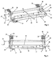
- the squeegee system (16) comprises (see Figures 3 and 4 ) a doctor blade support (18), a carrier hub (19) and a structure (21).
- the blade (17) is inserted into the doctor holder (18), so that its edge (22) protrudes and comes into contact with the engraved cylinder (11).
- the carrier hub (19) is made with two lateral cheeks (23) connected by a central piece (24).
- the structure (21) of the squeegee system (16) is formed by two side plates (26) which are fixed on corresponding uprights of the frame (6).
- the squeegee system (16) comprises adjustment means according to the format, that is to say according to the diameter of the engraved cylinder (11).
- These format adjustment means comprise a crank (27) meshing a series of pinions (28), to advance (Arrow F in Figure 3 ) or back (Arrow R in Figure 3 ) the carrier hub (19) along two rails in the structure (21).
- the squeegee system (16) comprises means for adjusting the angle of attack of the blade (17) with respect to the peripheral surface of the engraved cylinder (11), so as to optimize its scraping. These means for adjusting the angle rotate (Arrows A in Figure 3 ) the central piece (24) of the carrier hub (19), upwardly and downwardly relative to the two side flanges (23), with respect to an axis (X).
- the squeegee system (16) comprises means for causing the blade (17) to move back and forth (arrows B in Figures 3 and 4 ) on the peripheral surface of the engraved cylinder (11).
- These means comprise a finger (29) extending laterally from the doctor support (18).
- the finger (29) is actuated by motorized means (not shown in the Figures) outside the doctor blade system (16).
- the doctor blade holder (18) is mounted in a slide (not visible) formed in the upper surface of the central piece (24) of the carrier hub (19).
- the doctor blade support (18) has a lower portion passing through the central piece (24) of the carrier hub (19) and bearing against a return coil spring (31).
- the back-and-forth movement (B) is in a direction substantially parallel to the axis of revolution (O) of the engraved cylinder (11).
- the doctor blade support (18) slides laterally in one direction in the slide, being pushed by the finger (29), then slides laterally in another direction in the slide, being pushed by the coil spring (31).
- the squeegee system (16) comprises means for maintaining a constant contact of the entire length of the edge (22) of the blade (17) with the peripheral surface of the engraved cylinder (11).
- These means are two pushing elements, in the form of two springs (32). These two springs (32) are arranged laterally and act by moving and pushing (Arrows C) each side cheek (23) of the carrier hub (19). With this displacement of the carrier hub (19), the doctor blade holder (18) and the blade (17) move in the direction of the peripheral surface of the engraved cylinder (11).
- the two springs (32) placed laterally make it possible to exert a differential thrust on one side and / or on the other side of the carrier hub (19).
- the edge (22) of the blade (17) thus adapts to the irregularities of the peripheral surface and the mounting defects of the engraved cylinder (11) and remains pressed against the peripheral surface of the engraved cylinder (11).
- Each of the springs (32) is a flat spring fixed and respectively bearing on each of the two side plates (26) of the structure (21) of the doctor blade system (16).
- the carrier hub (19) moves linearly with respect to the structure (21) of the doctor system (16).
- the lateral cheeks (23) of the carrier hub (19) and the two side plates (26) of the structure (21) are arranged to allow movement of the carrier hub (19), the doctor blade support (18) and the blade (17) in the same plane as that formed by the blade (17).
Landscapes
- Engineering & Computer Science (AREA)
- Mechanical Engineering (AREA)
- Rotary Presses (AREA)
- Inking, Control Or Cleaning Of Printing Machines (AREA)
Abstract
Description
La présente invention concerne un système de racle, muni d'une racle. L'invention se rapporte également à un groupe imprimeur équipé d'un système de racle. L'invention concerne enfin une machine d'impression en héliogravure, intégrant au moins un groupe imprimeur.The present invention relates to a squeegee system, provided with a squeegee. The invention also relates to a printing unit equipped with a doctor blade system. The invention finally relates to a gravure printing machine, incorporating at least one printing unit.
L'héliogravure, également appelée hélio est un procédé d'impression rotatif utilisable pour de nombreux supports, dont le papier ou le carton, utilisant des cylindres gravés. L'impression en hélio est employée particulièrement pour les éditions de grande qualité et de grands tirages où le graphisme doit jouer un rôle important pour assurer la promotion d'un produit, tel qu'un emballage sous la forme d'une boîte en carton. Ce procédé d'impression permet en un seul passage d'imprimer jusqu'à dix couleurs, avec des encres à solvants, à l'eau ou autres ; d'imprimer des vernis mats, brillants ou structurés ; d'imprimer en recto et/ou en verso et de gaufrer.Photogravure, also called rotogravure, is a rotary printing process that can be used for many substrates, including paper or cardboard, using engraved cylinders. Gravure printing is used especially for high-quality editions and large prints where graphics must play an important role in promoting a product, such as a carton pack. This printing process makes it possible in one pass to print up to ten colors, with solvent, water or other inks; to print matt, glossy or structured varnishes; print on front and / or back and emboss.
Ainsi, dans une machine d'impression en hélio, un support à imprimer sous la forme d'une bande continue traverse une succession de groupes imprimeurs hélio. Les groupes imprimeurs sont assemblés et disposés les uns à la suite des autres depuis l'entrée du support à imprimer en amont jusqu'à sa sortie en aval. Chaque groupe imprimeur procède à l'impression d'un motif avec une seule couleur spécifique ou un vernis particulier, ou bien encore effectuant un gaufrage.Thus, in a gravure printing machine, a medium to be printed in the form of a continuous strip passes through a succession of gravure printing units. The printing units are assembled and arranged one after the other from the input of the print medium upstream to its output downstream. Each printing group proceeds to print a pattern with a single specific color or a particular varnish, or even embossing.
Le principe en hélio consiste à graver, sur la périphérie d'un cylindre d'impression, des alvéoles qui reproduisent le motif que l'on souhaite imprimer. Le cylindre gravé entraîné en rotation est recouvert d'encre grâce à un applicateur et tourne à l'intérieur d'une cuve contenant l'encre, ce qui permet de remplir les alvéoles. Le support à imprimer est ensuite appliqué fortement contre le cylindre gravé, de façon à ce que l'encre contenue dans les alvéoles puisse être extraite et transférée sur le support à imprimer.The principle in gravure is to engrave, on the periphery of a printing cylinder, cells that reproduce the pattern that you want to print. The engraved cylinder rotated is coated with ink by an applicator and rotates inside a tank containing the ink, which allows to fill the cells. The printing medium is then strongly applied against the engraved cylinder, so that the ink contained in the cells can be extracted and transferred onto the medium to be printed.
Un groupe imprimeur traditionnel comprend :
- un chariot imprimeur, présentant lui-même :
- un cylindre gravé,
- un applicateur d'encre, qui déverse l'encre sur le cylindre,
- un bac à encre, qui récupère le trop plein d'encre, et
- un système de racle, qui élimine le surplus d'encre sur le cylindre au moyen d'une lame de raclage, arasant la surface périphérique du cylindre et ne laissant que l'encre qui a pénétré dans les alvéoles ;
- un rouleau presseur, qui appuie fortement le support à imprimer sur le cylindre ;
- une pompe, qui assure l'acheminement de l'encre du réservoir à l'applicateur d'encre ; et
- un sécheur, qui assure l'évaporation rapide des solvants ou de l'eau, ou bien la polymérisation des encres à UV.
- a printer cart, presenting itself:
- an engraved cylinder,
- an ink applicator, which pours the ink on the cylinder,
- an ink tray, which recovers too much ink, and
- a squeegee system, which eliminates excess ink on the cylinder by means of a scraper blade, leveling the peripheral surface of the cylinder and leaving only the ink which has penetrated into the cells;
- a pressure roller, which strongly presses the support to be printed on the cylinder;
- a pump, which conveys the ink from the reservoir to the ink applicator; and
- a dryer, which ensures the rapid evaporation of solvents or water, or the polymerization of UV inks.
Si la qualité de l'impression dépend donc fortement de la qualité du cylindre gravé, le système de racle permet d'obtenir une qualité d'impression constante, en assurant le contrôle de la quantité d'encre contenue dans les alvéoles. La lame est mise en contact avec la surface du cylindre au niveau d'une ligne qui précède immédiatement, en suivant le sens de rotation du cylindre, la zone dans laquelle le cylindre vient contacter le support à imprimer.If the quality of the print depends greatly on the quality of the engraved cylinder, the squeegee system provides a constant print quality, ensuring control of the amount of ink contained in the cells. The blade is brought into contact with the surface of the cylinder at a line immediately preceding, following the direction of rotation of the cylinder, the zone in which the cylinder comes to contact the medium to be printed.
La lame est soumise à un mouvement de va-et-vient à la surface du cylindre, selon la direction parallèle à l'axe de révolution du cylindre. L'angle formé par le plan de la lame avec la surface du cylindre, également connu sous le terme angle d'attaque, est important pour éviter des vibrations de la lame ou pour empêcher des traînées d'encre. La pression de contact de la lame sur le cylindre doit également être ajustée, pour permettre à la surface de contact de l'arête de la lame contre le cylindre, ainsi qu'à l'angle d'attaque, de rester constants.The blade is subjected to a movement back and forth on the surface of the cylinder, in the direction parallel to the axis of revolution of the cylinder. The angle formed by the plane of the blade with the surface of the cylinder, also known as the angle of attack, is important to avoid vibrations of the blade or to prevent ink streaks. The contact pressure of the blade on the cylinder must also be adjusted, to allow the contact surface of the edge of the blade against the cylinder, as well as the angle of attack, to remain constant.
Le cylindre pour l'impression hélio possède des dimensions et un poids très important qui entraînent, d'une part, des difficultés de transport, et d'autre part, des difficultés de positionnement. Lors d'un changement de travail, le groupe cylindre-cuve est enlevé par le chariot imprimeur amovible, qui facilite sa manutention et sa permutation, comme le décrit par exemple le document
Ainsi, en raison des nombreux changements de cylindre, celui-ci se positionne avec des écarts par rapport au bâti du groupe imprimeur. Ces écarts, constituant un défaut de parallélisme entre la lame et le cylindre, engendrent un écartement entre l'arête longiligne de la lame et l'axe de rotation du cylindre. Ce phénomène implique la nécessité d'avoir un rattrapage pour la lame de raclage.Thus, because of the many cylinder changes, it is positioned with deviations from the frame of the printing unit. These differences, constituting a lack of parallelism between the blade and the cylinder, cause a spacing between the long line edge of the blade and the axis of rotation of the cylinder. This phenomenon implies the need to have a catch for the scraper blade.
Il arrive que le cylindre soit éventuellement gravé de manière désaxée, ou que le support à imprimer soit en biais à l'intérieur du groupe imprimeur. Pour corriger de tels défauts, engendrant des défauts à l'impression, une technique de réglage par désaxage du cylindre gravé, connue sous la dénomination de « skewing », est utilisée. Ce biaisage volontaire engendre un défaut de parallélisme entre le cylindre et la lame, qui doit être corrigé pour éviter tout raclage de mauvaise qualité.It happens that the cylinder is possibly etched off-axis, or that the support to be printed is skewed inside the printing unit. To correct such defects, resulting in printing defects, a technique of adjustment by offsetting the engraved cylinder, known under the name of "skewing", is used. This voluntary bias causes a defect of parallelism between the cylinder and the blade, which must be corrected to avoid scraping of poor quality.
On connaît d'après le document
Cependant, un tel dispositif présente l'inconvénient de posséder un point de pivotement, ce qui se traduit par l'existence d'un point de butée pour la lame, lorsqu'elle se déplace en direction de la surface à racler. La lame ne va pouvoir suivre de manière optimale la surface à racler.However, such a device has the disadvantage of having a pivot point, which results in the existence of a stop point for the blade when moving towards the surface to be scraped. The blade will not be able to optimally follow the surface to be scraped.
Le document
Cependant, avec un tel dispositif, le mécanisme de liaison pour suivre le déplacement du rouleau nettoyeur reste indispensable pour s'assurer que la lame vienne toucher la surface à essuyer. Etant donné que ce mécanisme de liaison est solidarisé latéralement par rapport au cylindre et que le cylindre hydraulique est fixé latéralement au porteur, le contact entre la racle et la surface va être très localisé en un seul point. De plus, les lumières allongées, limitent les mouvements du support de racle.However, with such a device, the connecting mechanism to follow the movement of the cleaning roller is essential to ensure that the blade comes touching the surface to be wiped. Since this linking mechanism is linked together Laterally with respect to the cylinder and the hydraulic cylinder is attached laterally to the carrier, the contact between the doctor blade and the surface will be very localized at a single point. In addition, the elongated lights limit the movements of the doctor blade support.
Le document
Cependant, les pistons assurent une pression constante, mais uniquement lorsqu'une partie de la lame entre bien en contact avec la surface périphérique du cylindre. De plus, la présence des tourillons pour le pivotement fait que la poussée des pistons contre le support de racle engendre des mouvements parasites de rotation. Enfin, le mouvement de va-et-vient entraîne également chacun des pistons.However, the pistons provide a constant pressure, but only when a portion of the blade comes into contact with the peripheral surface of the cylinder. In addition, the presence of the trunnions for pivoting causes the thrust of the pistons against the squeegee carrier causes rotational movements of rotation. Finally, the back and forth movement also drives each of the pistons.
Le document
Le document
Un problème principal que se propose de résoudre l'invention consiste à mettre au point un système de racle permettant un raclage optimal d'une surface périphérique du cylindre. Un deuxième problème est de réaliser un système de racle permettant à la fois un mouvement de va-et-vient de la lame et une efficacité optimale de raclage du cylindre avec cette même lame. Un troisième problème est celui de prévoir un système de racle restant à demeure dans un groupe imprimeur, tout en s'assurant de sa parfaite adaptation à chaque nouveau cylindre. Un quatrième problème est d'utiliser un système de racle qui soit indépendant du chariot imprimeur et donc du cylindre, avec plusieurs possibilités d'ajustement du système de racle par rapport au cylindre. Un cinquième problème est d'obtenir un système de racle pour un groupe imprimeur, qui soit à la fois simple et peu coûteux à réaliser. Un autre problème encore est de monter un système de racle dans un groupe imprimeur pour machine d'impression en héliogravure permettant de procurer une grande qualité d'impression.A main problem to be solved by the invention is to develop a squeegee system for optimal scraping of a peripheral surface of the cylinder. A second problem is to achieve a squeegee system allowing both a back and forth movement of the blade and an optimal scraping efficiency of the blade. cylinder with this same blade. A third problem is that of providing a squeegee system remaining permanently in a printing unit, while ensuring its perfect adaptation to each new cylinder. A fourth problem is to use a squeegee system that is independent of the printer carriage and therefore the cylinder, with several possibilities of adjustment of the squeegee system relative to the cylinder. A fifth problem is to obtain a squeegee system for a printing group, which is both simple and inexpensive to produce. Still another problem is to mount a squeegee system in a gravure printing machine printing unit to provide high print quality.
L'invention concerne un système de racle suivant la revendication 1.The invention relates to a doctor blade system according to claim 1.
Autrement dit, avec les moyens de l'invention, la lame du système de racle va toucher et rester constamment en contact avec le cylindre, quel que soit le positionnement angulaire de ce dernier par rapport à la lame. Par un déplacement libre et sans entrave de la lame en direction du cylindre, son arête rectiligne arrive à se poser sur la surface périphérique et à rester en butée sur toute sa longueur, lors de la rotation complète du cylindre. Si le cylindre possède des défauts de surface, des usures ou des imprécisions de montage, les moyens présents sur le système de racle viennent compenser les écarts, réguliers ou variables, existants ou survenant lorsque le cylindre effectue une révolution.In other words, with the means of the invention, the blade of the squeegee system will touch and remain constantly in contact with the cylinder, regardless of the angular positioning of the latter relative to the blade. By a free and unhindered movement of the blade towards the cylinder, its straight edge can land on the peripheral surface and remain in abutment along its length, during the complete rotation of the cylinder. If the cylinder has surface defects, wear or mounting inaccuracies, the means present on the squeegee system compensate for the differences, regular or variable, existing or occurring when the cylinder performs a revolution.
Les réglages fins de la pression exercée par l'arête de la lame sur la surface périphérique du cylindre ne sont pas assurés par les éléments de poussée. L'objectif est de conserver un contact linéique de l'arête de la lame sur la surface périphérique du cylindre en rotation. Un tel contact va être obtenu à chaque changement de cylindres, lorsque des nouveaux travaux sont demandés.The fine adjustments of the pressure exerted by the edge of the blade on the peripheral surface of the cylinder are not ensured by the pushing elements. The goal is to maintain a linear contact of the edge of the blade on the surface rotating cylinder device. Such contact will be obtained with each change of cylinder, when new work is requested.
Les moyens de va-et-vient sont utilisés pour éviter une usure localisée trop rapide de la lame, portant préjudice à la qualité de l'impression. Le système de racle combine ainsi pour la lame une aptitude à se déplacer librement, jusqu'à ce que celle-ci entre et reste constamment en contact avec la surface du cylindre, et une capacité à effectuer des allers-retours au niveau de cette surface de ce cylindre. De plus, les moyens pour assurer un mouvement de va-et-vient de la lame font uniquement déplacer le support de racle et sa lame, sans les éléments de poussée, ce qui se traduit par un allègement des pièces en mouvement rapide.The back and forth means are used to prevent localized wear too fast blade, detrimental to the quality of printing. The doctor blade system thus combines for the blade an ability to move freely, until it enters and remains in constant contact with the surface of the cylinder, and an ability to go back and forth at that surface. of this cylinder. In addition, the means to ensure a movement back and forth of the blade only move the doctor blade holder and blade, without the thrust elements, which results in a lightening of fast moving parts.
Les éléments de poussée génèrent des forces de poussée s'exerçant sur le moyeu porteur. Ces forces peuvent être orientées dans le plan défini par la lame. Le système de racle peut comprendre deux éléments de poussée, pouvant se présenter avantageusement sous la forme de deux ressorts. Ces moyens d'application de la poussée pour assurer un maintien du contact sont élastiques. Ces deux ressorts peuvent être disposés latéralement, des deux côtés du moyeu porteur, de façon à pouvoir pousser chaque côté de ce moyeu porteur, en direction de la surface périphérique du cylindre gravé.The thrust elements generate thrust forces acting on the hub carrier. These forces can be oriented in the plane defined by the blade. The doctor blade system may comprise two thrust elements, which may advantageously be in the form of two springs. These means of applying the thrust to maintain the contact are elastic. These two springs can be arranged laterally, on both sides of the carrier hub, so as to push each side of the carrier hub, towards the peripheral surface of the engraved cylinder.
De manière favorable, le système peut comprendre des moyens pour compenser un couple induit par le mouvement de va-et-vient de la lame. Le couple est induit par le degré de liberté supplémentaire conféré au moyeu porteur, au support de racle et à la lame, associé au mouvement alternatif du support de racle et de la lame. Les moyens pour compenser le couple peuvent comprendre une rondelle, montée à une extrémité d'un axe de rotation du moyeu porteur. Cet axe de rotation permet le réglage d'un angle entre la lame et la surface périphérique du cylindre gravé et constitue un point d'attache du moyeu porteur avec la structure.Favorably, the system may comprise means for compensating a torque induced by the movement of the back and forth of the blade. The torque is induced by the additional degree of freedom imparted to the hub carrier, squeegee support and blade, associated with the reciprocating movement of the doctor carrier and the blade. The means for compensating the torque may comprise a washer, mounted at one end of an axis of rotation of the carrier hub. This axis of rotation allows the adjustment of an angle between the blade and the peripheral surface of the engraved cylinder and constitutes a point of attachment of the carrier hub with the structure.
Les moyens pour assurer un mouvement de va-et-vient de la lame peuvent comprendre un doigt d'impulsion faisant saillie à partir du support de racle. Ce doigt peut entrer en contact avec des moyens d'impulsion pour le va-et-vient, qui sont motorisés, et indépendants du système de racle. Les moyens pour assurer un mouvement de va-et-vient de la lame peuvent comprendre un ressort de rappel, positionné entre le support de racle et le moyeu porteur, et assurant un retour libre du support de racle, après impulsion.The means for reciprocating the blade may include a pulse finger projecting from the doctor support. This finger can come into contact with pulse means for the back and forth, which are motorized and independent of the doctor blade system. The means for reciprocating the blade may comprise a return spring, positioned between the doctor support and the carrier hub, and providing a free return of the blade. squeegee support, after impulse.
Conformément à un deuxième aspect de la présente invention, un groupe imprimeur est caractérisé en ce qu'il est équipé avec un système de racle présentant une ou plusieurs des caractéristiques techniques décrites ci-dessus.According to a second aspect of the present invention, a printing unit is characterized in that it is equipped with a doctor blade system having one or more of the technical features described above.
Conformément à un troisième aspect de la présente invention, une machine d'impression en héliogravure est caractérisée en ce qu'elle comprend au moins un groupe imprimeur muni d'un système de racle présentant une ou plusieurs des caractéristiques techniques décrites ci-dessus.According to a third aspect of the present invention, a gravure printing machine is characterized in that it comprises at least one printing unit provided with a doctor blade system having one or more of the technical characteristics described above.
L'invention sera bien comprise et ses divers avantages et différentes caractéristiques ressortiront mieux lors de la description suivante, de l'exemple non limitatif de réalisation, en référence aux dessins schématiques annexés, dans lesquels :
- la
Figure 1 représente une vue simplifiée, latérale, en élévation, de deux groupes imprimeurs successifs, faisant partie d'une machine d'impression en héliogravure ; - la
Figure 2 représente une vue simplifiée, latérale, en élévation d'un chariot imprimeur ; - la
Figure 3 représente une vue en perspective du système de racle selon l'invention ; et - la
Figure 4 représente une vue du dessus du système de racle selon l'invention.
- the
Figure 1 is a simplified, side elevational view of two successive printing units forming part of a gravure printing machine; - the
Figure 2 represents a simplified, side elevational view of a printer carriage; - the
Figure 3 represents a perspective view of the doctor blade system according to the invention; and - the
Figure 4 represents a view from above of the doctor blade system according to the invention.
Comme l'illustre la
Chaque groupe imprimeur (2 et 3) comprend un bâti (6), un chariot imprimeur (7) inséré au centre du bâti (6), un sécheur (8), un rouleau presseur (9) et une pompe (non représentée dans les Figures) qui assure l'alimentation en encre. En raison du mécanisme de cheminement du support à imprimer (4), le premier groupe imprimeur (2) réalise une impression recto et le deuxième groupe imprimeur (3) réalise une impression verso de ce même support à imprimer (4).Each printer unit (2 and 3) comprises a frame (6), a printer carriage (7) inserted in the center of the frame (6), a dryer (8), a pressure roller (9) and a pump (not shown in FIGS. Figures) which provides the ink supply. Due to the routing mechanism of the medium to be printed (4), the first printing unit (2) performs a single-sided printing and the second printing unit (3) performs a back printing of the same medium to be printed (4).
Le chariot imprimeur (7) comprend (voir
Le support à imprimer (4) est fortement pressé (
Le système de racle (16) est solidarisé au bâti (6) de chaque groupe imprimeur (2 et 3). Il est à noter que (voir
Le système de racle (16) comprend (voir
Le système de racle (16) comprend des moyens de réglage selon le format, c'est-à-dire en fonction du diamètre du cylindre gravé (11). Ces moyens de réglage au format comprennent une manivelle (27) engrenant une série de pignons (28), pour faire avancer (Flèche F en
Le système de racle (16) comprend des moyens de réglage de l'angle d'attaque de la lame (17) par rapport à la surface périphérique du cylindre gravé (11), de façon à optimiser son raclage. Ces moyens de réglage de l'angle font pivoter (Flèches A en
Le système de racle (16) comprend des moyens pour faire effectuer à la lame (17) un mouvement de va-et-vient (Flèches B en
Le mouvement de va-et-vient (B) se fait selon une direction sensiblement parallèle à l'axe de révolution (O) du cylindre gravé (11). Le support de racle (18) coulisse latéralement dans un sens dans la glissière, en étant poussé par le doigt (29), puis coulisse latéralement dans un autre sens dans la glissière, en étant repoussé par le ressort hélicoïdal (31).The back-and-forth movement (B) is in a direction substantially parallel to the axis of revolution (O) of the engraved cylinder (11). The doctor blade support (18) slides laterally in one direction in the slide, being pushed by the finger (29), then slides laterally in another direction in the slide, being pushed by the coil spring (31).
Selon l'invention, le système de racle (16) comprend des moyens destinés à conserver un contact constant de toute la longueur de l'arête (22) de la lame (17) avec la surface périphérique du cylindre gravé (11). Ces moyens sont deux éléments de poussée, sous la forme de deux ressorts (32). Ces deux ressorts (32), sont disposés latéralement, et agissent en déplaçant et en poussant (Flèches C) chaque joue latérale (23) du moyeu porteur (19). Avec ce déplacement du moyeu porteur (19), le support de racle (18) et la lame (17) se déplacent en direction de la surface périphérique du cylindre gravé (11).According to the invention, the squeegee system (16) comprises means for maintaining a constant contact of the entire length of the edge (22) of the blade (17) with the peripheral surface of the engraved cylinder (11). These means are two pushing elements, in the form of two springs (32). These two springs (32) are arranged laterally and act by moving and pushing (Arrows C) each side cheek (23) of the carrier hub (19). With this displacement of the carrier hub (19), the doctor blade holder (18) and the blade (17) move in the direction of the peripheral surface of the engraved cylinder (11).
Les deux ressorts (32) placés latéralement permettent d'exercer une poussée différentielle d'un côté et/ou de l'autre côté du moyeu porteur (19). L'arête (22) de la lame (17) s'adapte ainsi aux irrégularités de la surface périphérique et aux défauts de montage du cylindre gravé (11) et reste plaquée contre la surface périphérique du cylindre gravé (11).The two springs (32) placed laterally make it possible to exert a differential thrust on one side and / or on the other side of the carrier hub (19). The edge (22) of the blade (17) thus adapts to the irregularities of the peripheral surface and the mounting defects of the engraved cylinder (11) and remains pressed against the peripheral surface of the engraved cylinder (11).
Chacun des ressorts (32) est un ressort plat fixé et prenant respectivement appui sur chacune des deux plaques latérales (26) de la structure (21) du système de racle (16). Le moyeu porteur (19) se déplace de manière linéaire par rapport à la structure (21) du système de racle (16).Each of the springs (32) is a flat spring fixed and respectively bearing on each of the two side plates (26) of the structure (21) of the doctor blade system (16). The carrier hub (19) moves linearly with respect to the structure (21) of the doctor system (16).
Les joues latérales (23) du moyeu porteur (19) et les deux plaques latérales (26) de la structure (21) sont agencées pour permettre un déplacement du moyeu porteur (19), du support de racle (18) et de la lame (17) dans le même plan que celui que forme la lame (17).The lateral cheeks (23) of the carrier hub (19) and the two side plates (26) of the structure (21) are arranged to allow movement of the carrier hub (19), the doctor blade support (18) and the blade (17) in the same plane as that formed by the blade (17).
Lorsque le mouvement de va-et-vient (B) de la lame (17) s'effectue en même temps qu'un déplacement pour conserver un contact constant de toute la longueur de l'arête (22) de la lame (17) avec la surface périphérique du cylindre gravé (11), il se crée un couple parasite induit au niveau du moyeu porteur (19). Pour ce faire, une rondelle (33) est montée à une extrémité d'un axe de rotation (X) du moyeu porteur (19) permettant le réglage (A) d'un angle entre la lame (17) et la surface périphérique du cylindre gravé (11).When the reciprocating movement (B) of the blade (17) is performed at the same time as a movement to maintain a constant contact along the entire length of the edge (22) of the blade (17) with the peripheral surface of the engraved cylinder (11), an induced parasitic torque is created at the level of the carrier hub (19). To do this, a washer (33) is mounted at one end of an axis of rotation (X) of the carrier hub (19) allowing adjustment (A) of an angle between the blade (17) and the peripheral surface of the engraved cylinder (11).
Claims (7)
- Doctor blade system, intended for a print unit (2, 3) provided with an engraved cylinder (11), comprising:- a doctor blade support (18) provided with a blade (17), an edge (22) of the blade (17) being able to come into contact with a peripheral surface of the engraved cylinder (11),- a supporting hub (19), on which the doctor blade support (18) is mounted,- a structure (21), fixing the supporting hub (19) to a frame (6) of the print unit (2, 3),- means for providing a reciprocating motion (B) of the blade (17) on the peripheral surface of the engraved cylinder (11), along a direction substantially parallel to the axis of revolution (O) of said engraved cylinder (11), and directly driving the doctor blade support (18) provided with the blade (17),characterized in that it comprises thrust elements, bearing on the structure (21), generating forces exerted on the supporting hub (19), moving the supporting hub (19) and the doctor blade support (18) provided with the blade (17), and driving a movement of the blade (17) in the direction of said peripheral surface of said engraved cylinder (11), so as to maintain a constant contact over the entire length of the edge (22) of the blade (17) with the peripheral surface of the engraved cylinder (11).
- System according to claim 1, characterized in that it comprises two thrust elements, in the form of two springs (32), arranged laterally on both sides of the supporting hub (19), so as to thrust each side of said supporting hub (19) in the direction of the peripheral surface of the engraved cylinder (11).
- System according to claim 1 or 2, characterized in that it comprises means for compensating a torque created by the reciprocating motion (B) of the blade (17).
- System according to claim 3, characterized in that the means for compensating the torque comprise a washer (33) mounted at one end of an axis of rotation (X) of the supporting hub (19) enabling the adjustment (A) of an angle between the blade (17) and the peripheral surface of the engraved cylinder (11).
- System according to any one of the preceding claims, characterized in that the means for providing a reciprocating motion (B) of the blade (17) comprise a push arm (29) projecting from the doctor blade support (18), coming into contact with motorized reciprocating means, and a return spring (31) positioned between the doctor blade support (18) and the supporting hub (19).
- Print unit, characterized in that it is equipped with a doctor blade system (16) according to any one of the preceding claims.
- Photogravure printing machine, characterized in that it comprise at least one print unit (2, 3) provided with a doctor blade system (16) according to any one of claims 1 to 5.
Priority Applications (1)
| Application Number | Priority Date | Filing Date | Title |
|---|---|---|---|
| EP08734819A EP2139683B1 (en) | 2007-04-27 | 2008-03-28 | Doctor blade system for a printing unit, intended for an intaglio printing machine |
Applications Claiming Priority (3)
| Application Number | Priority Date | Filing Date | Title |
|---|---|---|---|
| EP07008586 | 2007-04-27 | ||
| PCT/EP2008/002441 WO2008141694A1 (en) | 2007-04-27 | 2008-03-28 | Doctor blade system for a printing unit, intended for an intaglio printing machine |
| EP08734819A EP2139683B1 (en) | 2007-04-27 | 2008-03-28 | Doctor blade system for a printing unit, intended for an intaglio printing machine |
Publications (2)
| Publication Number | Publication Date |
|---|---|
| EP2139683A1 EP2139683A1 (en) | 2010-01-06 |
| EP2139683B1 true EP2139683B1 (en) | 2011-12-28 |
Family
ID=38627024
Family Applications (1)
| Application Number | Title | Priority Date | Filing Date |
|---|---|---|---|
| EP08734819A Active EP2139683B1 (en) | 2007-04-27 | 2008-03-28 | Doctor blade system for a printing unit, intended for an intaglio printing machine |
Country Status (7)
| Country | Link |
|---|---|
| US (1) | US8915184B2 (en) |
| EP (1) | EP2139683B1 (en) |
| JP (1) | JP5130577B2 (en) |
| CN (1) | CN101668635B (en) |
| AT (1) | ATE538928T1 (en) |
| ES (1) | ES2375886T3 (en) |
| WO (1) | WO2008141694A1 (en) |
Families Citing this family (7)
| Publication number | Priority date | Publication date | Assignee | Title |
|---|---|---|---|---|
| KR101779025B1 (en) * | 2013-04-02 | 2017-09-18 | 한화테크윈 주식회사 | Squeezee apparatus of semi-automatic replacement blade |
| CN103331990B (en) * | 2013-07-16 | 2014-12-17 | 大理美登印务有限公司 | Improved type doctor blade locking and adjusting device for intaglio printing press |
| EP3445586B1 (en) * | 2016-04-22 | 2024-04-17 | Bobst Italia S.P.A. | A doctor blade assembly with support in a rotogravure printing unit |
| CN106739479B (en) * | 2016-12-12 | 2024-11-26 | 南京数维软件科技有限公司 | A printing unit for a cloth printing line |
| CN106696458A (en) * | 2016-12-12 | 2017-05-24 | 泉州市西格玛智能工业机械有限公司 | Printing part of cloth printing assembly line |
| CN106541700B (en) * | 2016-12-12 | 2025-05-13 | 泉州市西格玛智能工业机械有限公司 | A printing roller scraper mechanism for a cloth printing line |
| FR3084013B1 (en) * | 2018-07-18 | 2020-07-31 | Bobst Lyon | SQUEEGEE, SQUEEGEE CHAMBER AND PRINTER UNIT THUS EQUIPPED |
Family Cites Families (20)
| Publication number | Priority date | Publication date | Assignee | Title |
|---|---|---|---|---|
| DE238265C (en) | ||||
| GB474850A (en) | 1936-08-10 | 1937-11-09 | Friedrich Von Heinrich | Improvements in or relating to plate-wiping devices for intaglio printing machines |
| US2377110A (en) * | 1943-09-15 | 1945-05-29 | Rice Barton Corp | Printing roll inking device |
| US4151797A (en) * | 1977-05-04 | 1979-05-01 | Mid America Tag And Label Company, Inc. | Doctor blade apparatus |
| US4367120A (en) * | 1980-03-13 | 1983-01-04 | Vickerys Limited | Doctor blade mounting assembly |
| DE3039326A1 (en) | 1980-10-17 | 1982-05-06 | Windmöller & Hölscher, 4540 Lengerich | BLADE WITH A THIS FLOATING DRIVE |
| US4398463A (en) | 1981-08-19 | 1983-08-16 | Motter Printing Press Co. | Non-repeat doctor blade drive |
| FR2539325A1 (en) | 1983-01-17 | 1984-07-20 | Armotek Ind Inc | Powder feed device for applying wear-resistant coatings to objects |
| JPH0777795B2 (en) | 1986-04-25 | 1995-08-23 | 大日本印刷株式会社 | Doctor device for printing machine |
| DD275992A3 (en) | 1988-03-07 | 1990-02-14 | Inst Spielzeug Sonneberg Veb | RAKELMESSERHALTER WITH SELF-TIMING RAKEL PRESSURE COMPENSATION |
| DE3933844A1 (en) | 1989-10-10 | 1991-04-18 | Windmoeller & Hoelscher | Squeegee device |
| DE9218039U1 (en) * | 1992-04-25 | 1993-06-03 | Koenig & Bauer AG, 8700 Würzburg | Doctor bar for a short inking unit of a web-fed rotary printing press |
| DE4425478A1 (en) * | 1994-07-19 | 1996-02-08 | Roland Man Druckmasch | Chamber squeegee |
| DE4440648A1 (en) | 1994-11-14 | 1996-05-15 | Windmoeller & Hoelscher | Doctor device for gravure printing machines |
| JP3421485B2 (en) | 1995-09-27 | 2003-06-30 | 株式会社小森コーポレーション | Wiping device for intaglio printing press |
| JPH1071692A (en) | 1996-08-30 | 1998-03-17 | Dainippon Printing Co Ltd | Gravure printing table test machine |
| EP0980312B1 (en) * | 1997-05-05 | 2002-07-31 | Koenig & Bauer Aktiengesellschaft | Bearing for a rotary press cylinder |
| JP4666781B2 (en) | 2001-01-29 | 2011-04-06 | 大日本印刷株式会社 | Doctor swing device |
| JP2005034733A (en) | 2003-07-14 | 2005-02-10 | Tomoegawa Paper Co Ltd | Gravure coating apparatus and gravure coating method |
| ITMI20031539A1 (en) * | 2003-07-25 | 2003-10-24 | Percivalle Special Converting S A S Di Percivall | INKING AND RACLING UNIT FOR A ROTOCALCOGRAPHIC PRINTING AND COATING GROUP. |
-
2008
- 2008-03-28 US US12/597,320 patent/US8915184B2/en active Active
- 2008-03-28 CN CN200880013599.5A patent/CN101668635B/en active Active
- 2008-03-28 WO PCT/EP2008/002441 patent/WO2008141694A1/en not_active Ceased
- 2008-03-28 EP EP08734819A patent/EP2139683B1/en active Active
- 2008-03-28 ES ES08734819T patent/ES2375886T3/en active Active
- 2008-03-28 AT AT08734819T patent/ATE538928T1/en active
- 2008-03-28 JP JP2010503369A patent/JP5130577B2/en active Active
Also Published As
| Publication number | Publication date |
|---|---|
| US8915184B2 (en) | 2014-12-23 |
| JP5130577B2 (en) | 2013-01-30 |
| ATE538928T1 (en) | 2012-01-15 |
| CN101668635A (en) | 2010-03-10 |
| WO2008141694A1 (en) | 2008-11-27 |
| JP2010523380A (en) | 2010-07-15 |
| CN101668635B (en) | 2012-08-08 |
| EP2139683A1 (en) | 2010-01-06 |
| ES2375886T3 (en) | 2012-03-07 |
| US20100116158A1 (en) | 2010-05-13 |
Similar Documents
| Publication | Publication Date | Title |
|---|---|---|
| EP2139683B1 (en) | Doctor blade system for a printing unit, intended for an intaglio printing machine | |
| EP2064062B1 (en) | Device for printing by transfer onto a cylindrical print support | |
| EP0095423B1 (en) | Variable-size offset printing apparatus | |
| FR2501112A1 (en) | ROTARY OFFSET SHEET PRINTING MACHINE FOR PERFORMING A UNILATERAL COLOR PRINTING OR A RECTO-VERSO PRINTING | |
| FR2550994A1 (en) | DEVICE FOR ANCHORING A ROCKER CYLINDER AND PRINTING METHOD WITHOUT DEFECT | |
| FR2552022A1 (en) | METHOD FOR PRINTING INTO HOLES, AND PRINTING PLATES FOR SUCH A METHOD | |
| FR2624793A1 (en) | ANCHORING-INCHING DEVICE FOR OFFSET PRINTING PRESSES | |
| EP0885720B1 (en) | Multifuntional inking device for a flexographic printing machine | |
| FR2697772A1 (en) | Sheet cutting method for a plotter | |
| EP0564372B1 (en) | Offset printing machine | |
| EP1504905B1 (en) | On the fly ink-jet nozzle cleaning device | |
| FR2828833A1 (en) | MULTI-MODES CONTINUOUS PRINTING PROCESS | |
| EP2139684B1 (en) | Methods for assembly disassembly and transformation of a printing group for a printing press and a corresponding transport device | |
| EP2271564B1 (en) | Device for conveying a flat substrate, comprising a cleaning device, and corresponding cutting device, printing press, and use of said device | |
| EP1938971B1 (en) | Coupling device for powering a cylinder of a printing device | |
| FR2765829A1 (en) | OFFSET PRINTING UNIT FOR LACQUERING PRINTING MATERIALS IN A ROTARY PRINTING MACHINE | |
| EP0706456A1 (en) | Device for the adjustment of a flexographic printing machine unit | |
| FR2468469A1 (en) | PRINTING DEVICE COMPRISING ONE OR MORE PADS ARRANGED ON A MOBILE CARRIER ELEMENT IN THE VERTICAL DIRECTION | |
| FR2826909A1 (en) | IMPACT MARKING AND / OR PRINTING DEVICE | |
| BE901555A (en) | Rotary offset duplex printing machine with single pass - has cylinder contacting offset plate carriers and second cylinder acting as colour collection, printing both sides simultaneously | |
| CH300043A (en) | Method for wetting a printing plate and device for implementing this method. | |
| CH684469A5 (en) | Device for sheets emerging from a printer | |
| FR2648750A1 (en) | INK ROLLER INKING DEVICE FOR ROTARY PRINTING MACHINE | |
| WO2025105945A1 (en) | Machine for the semi-automatic screen-printing of foams | |
| FR2957297A3 (en) | Installation for applying scenery e.g. paper scenery, on furniture element in panel e.g. raw panel, has pressurization device supporting cylinder in active position against surface of panel or passing cylinder to disengaged position |
Legal Events
| Date | Code | Title | Description |
|---|---|---|---|
| PUAI | Public reference made under article 153(3) epc to a published international application that has entered the european phase |
Free format text: ORIGINAL CODE: 0009012 |
|
| 17P | Request for examination filed |
Effective date: 20091013 |
|
| AK | Designated contracting states |
Kind code of ref document: A1 Designated state(s): AT BE BG CH CY CZ DE DK EE ES FI FR GB GR HR HU IE IS IT LI LT LU LV MC MT NL NO PL PT RO SE SI SK TR |
|
| 17Q | First examination report despatched |
Effective date: 20100211 |
|
| DAX | Request for extension of the european patent (deleted) | ||
| GRAP | Despatch of communication of intention to grant a patent |
Free format text: ORIGINAL CODE: EPIDOSNIGR1 |
|
| GRAS | Grant fee paid |
Free format text: ORIGINAL CODE: EPIDOSNIGR3 |
|
| GRAA | (expected) grant |
Free format text: ORIGINAL CODE: 0009210 |
|
| AK | Designated contracting states |
Kind code of ref document: B1 Designated state(s): AT BE BG CH CY CZ DE DK EE ES FI FR GB GR HR HU IE IS IT LI LT LU LV MC MT NL NO PL PT RO SE SI SK TR |
|
| REG | Reference to a national code |
Ref country code: GB Ref legal event code: FG4D Free format text: NOT ENGLISH |
|
| REG | Reference to a national code |
Ref country code: CH Ref legal event code: EP |
|
| REG | Reference to a national code |
Ref country code: AT Ref legal event code: REF Ref document number: 538928 Country of ref document: AT Kind code of ref document: T Effective date: 20120115 |
|
| REG | Reference to a national code |
Ref country code: IE Ref legal event code: FG4D |
|
| REG | Reference to a national code |
Ref country code: NL Ref legal event code: T3 |
|
| REG | Reference to a national code |
Ref country code: ES Ref legal event code: FG2A Ref document number: 2375886 Country of ref document: ES Kind code of ref document: T3 Effective date: 20120307 |
|
| REG | Reference to a national code |
Ref country code: DE Ref legal event code: R096 Ref document number: 602008012347 Country of ref document: DE Effective date: 20120308 |
|
| PG25 | Lapsed in a contracting state [announced via postgrant information from national office to epo] |
Ref country code: NO Free format text: LAPSE BECAUSE OF FAILURE TO SUBMIT A TRANSLATION OF THE DESCRIPTION OR TO PAY THE FEE WITHIN THE PRESCRIBED TIME-LIMIT Effective date: 20120328 Ref country code: LT Free format text: LAPSE BECAUSE OF FAILURE TO SUBMIT A TRANSLATION OF THE DESCRIPTION OR TO PAY THE FEE WITHIN THE PRESCRIBED TIME-LIMIT Effective date: 20111228 |
|
| LTIE | Lt: invalidation of european patent or patent extension |
Effective date: 20111228 |
|
| PG25 | Lapsed in a contracting state [announced via postgrant information from national office to epo] |
Ref country code: SE Free format text: LAPSE BECAUSE OF FAILURE TO SUBMIT A TRANSLATION OF THE DESCRIPTION OR TO PAY THE FEE WITHIN THE PRESCRIBED TIME-LIMIT Effective date: 20111228 Ref country code: GR Free format text: LAPSE BECAUSE OF FAILURE TO SUBMIT A TRANSLATION OF THE DESCRIPTION OR TO PAY THE FEE WITHIN THE PRESCRIBED TIME-LIMIT Effective date: 20120329 Ref country code: HR Free format text: LAPSE BECAUSE OF FAILURE TO SUBMIT A TRANSLATION OF THE DESCRIPTION OR TO PAY THE FEE WITHIN THE PRESCRIBED TIME-LIMIT Effective date: 20111228 Ref country code: SI Free format text: LAPSE BECAUSE OF FAILURE TO SUBMIT A TRANSLATION OF THE DESCRIPTION OR TO PAY THE FEE WITHIN THE PRESCRIBED TIME-LIMIT Effective date: 20111228 Ref country code: LV Free format text: LAPSE BECAUSE OF FAILURE TO SUBMIT A TRANSLATION OF THE DESCRIPTION OR TO PAY THE FEE WITHIN THE PRESCRIBED TIME-LIMIT Effective date: 20111228 |
|
| PG25 | Lapsed in a contracting state [announced via postgrant information from national office to epo] |
Ref country code: CY Free format text: LAPSE BECAUSE OF FAILURE TO SUBMIT A TRANSLATION OF THE DESCRIPTION OR TO PAY THE FEE WITHIN THE PRESCRIBED TIME-LIMIT Effective date: 20111228 |
|
| REG | Reference to a national code |
Ref country code: IE Ref legal event code: FD4D |
|
| RAP2 | Party data changed (patent owner data changed or rights of a patent transferred) |
Owner name: BOBST MEX SA |
|
| PG25 | Lapsed in a contracting state [announced via postgrant information from national office to epo] |
Ref country code: CZ Free format text: LAPSE BECAUSE OF FAILURE TO SUBMIT A TRANSLATION OF THE DESCRIPTION OR TO PAY THE FEE WITHIN THE PRESCRIBED TIME-LIMIT Effective date: 20111228 Ref country code: SK Free format text: LAPSE BECAUSE OF FAILURE TO SUBMIT A TRANSLATION OF THE DESCRIPTION OR TO PAY THE FEE WITHIN THE PRESCRIBED TIME-LIMIT Effective date: 20111228 Ref country code: IE Free format text: LAPSE BECAUSE OF FAILURE TO SUBMIT A TRANSLATION OF THE DESCRIPTION OR TO PAY THE FEE WITHIN THE PRESCRIBED TIME-LIMIT Effective date: 20111228 Ref country code: BG Free format text: LAPSE BECAUSE OF FAILURE TO SUBMIT A TRANSLATION OF THE DESCRIPTION OR TO PAY THE FEE WITHIN THE PRESCRIBED TIME-LIMIT Effective date: 20120328 Ref country code: IS Free format text: LAPSE BECAUSE OF FAILURE TO SUBMIT A TRANSLATION OF THE DESCRIPTION OR TO PAY THE FEE WITHIN THE PRESCRIBED TIME-LIMIT Effective date: 20120428 Ref country code: EE Free format text: LAPSE BECAUSE OF FAILURE TO SUBMIT A TRANSLATION OF THE DESCRIPTION OR TO PAY THE FEE WITHIN THE PRESCRIBED TIME-LIMIT Effective date: 20111228 |
|
| PG25 | Lapsed in a contracting state [announced via postgrant information from national office to epo] |
Ref country code: RO Free format text: LAPSE BECAUSE OF FAILURE TO SUBMIT A TRANSLATION OF THE DESCRIPTION OR TO PAY THE FEE WITHIN THE PRESCRIBED TIME-LIMIT Effective date: 20111228 Ref country code: PT Free format text: LAPSE BECAUSE OF FAILURE TO SUBMIT A TRANSLATION OF THE DESCRIPTION OR TO PAY THE FEE WITHIN THE PRESCRIBED TIME-LIMIT Effective date: 20120430 Ref country code: PL Free format text: LAPSE BECAUSE OF FAILURE TO SUBMIT A TRANSLATION OF THE DESCRIPTION OR TO PAY THE FEE WITHIN THE PRESCRIBED TIME-LIMIT Effective date: 20111228 |
|
| REG | Reference to a national code |
Ref country code: CH Ref legal event code: PFA Owner name: BOBST MEX SA Free format text: BOBST SA#CASE POSTALE#1001 LAUSANNE (CH) -TRANSFER TO- BOBST MEX SA#ROUTE DE FARAZ 3#1031 MEX (CH) |
|
| REG | Reference to a national code |
Ref country code: AT Ref legal event code: MK05 Ref document number: 538928 Country of ref document: AT Kind code of ref document: T Effective date: 20111228 |
|
| BERE | Be: lapsed |
Owner name: BOBST SA Effective date: 20120331 |
|
| PG25 | Lapsed in a contracting state [announced via postgrant information from national office to epo] |
Ref country code: MC Free format text: LAPSE BECAUSE OF NON-PAYMENT OF DUE FEES Effective date: 20120331 Ref country code: DK Free format text: LAPSE BECAUSE OF FAILURE TO SUBMIT A TRANSLATION OF THE DESCRIPTION OR TO PAY THE FEE WITHIN THE PRESCRIBED TIME-LIMIT Effective date: 20111228 |
|
| PLBE | No opposition filed within time limit |
Free format text: ORIGINAL CODE: 0009261 |
|
| STAA | Information on the status of an ep patent application or granted ep patent |
Free format text: STATUS: NO OPPOSITION FILED WITHIN TIME LIMIT |
|
| GBPC | Gb: european patent ceased through non-payment of renewal fee |
Effective date: 20120328 |
|
| 26N | No opposition filed |
Effective date: 20121001 |
|
| REG | Reference to a national code |
Ref country code: DE Ref legal event code: R097 Ref document number: 602008012347 Country of ref document: DE Effective date: 20121001 |
|
| PG25 | Lapsed in a contracting state [announced via postgrant information from national office to epo] |
Ref country code: AT Free format text: LAPSE BECAUSE OF FAILURE TO SUBMIT A TRANSLATION OF THE DESCRIPTION OR TO PAY THE FEE WITHIN THE PRESCRIBED TIME-LIMIT Effective date: 20111228 Ref country code: BE Free format text: LAPSE BECAUSE OF NON-PAYMENT OF DUE FEES Effective date: 20120331 Ref country code: GB Free format text: LAPSE BECAUSE OF NON-PAYMENT OF DUE FEES Effective date: 20120328 |
|
| PG25 | Lapsed in a contracting state [announced via postgrant information from national office to epo] |
Ref country code: FI Free format text: LAPSE BECAUSE OF FAILURE TO SUBMIT A TRANSLATION OF THE DESCRIPTION OR TO PAY THE FEE WITHIN THE PRESCRIBED TIME-LIMIT Effective date: 20111228 |
|
| PG25 | Lapsed in a contracting state [announced via postgrant information from national office to epo] |
Ref country code: MT Free format text: LAPSE BECAUSE OF FAILURE TO SUBMIT A TRANSLATION OF THE DESCRIPTION OR TO PAY THE FEE WITHIN THE PRESCRIBED TIME-LIMIT Effective date: 20111228 |
|
| PG25 | Lapsed in a contracting state [announced via postgrant information from national office to epo] |
Ref country code: TR Free format text: LAPSE BECAUSE OF FAILURE TO SUBMIT A TRANSLATION OF THE DESCRIPTION OR TO PAY THE FEE WITHIN THE PRESCRIBED TIME-LIMIT Effective date: 20111228 |
|
| PG25 | Lapsed in a contracting state [announced via postgrant information from national office to epo] |
Ref country code: LU Free format text: LAPSE BECAUSE OF NON-PAYMENT OF DUE FEES Effective date: 20120328 |
|
| PG25 | Lapsed in a contracting state [announced via postgrant information from national office to epo] |
Ref country code: HU Free format text: LAPSE BECAUSE OF FAILURE TO SUBMIT A TRANSLATION OF THE DESCRIPTION OR TO PAY THE FEE WITHIN THE PRESCRIBED TIME-LIMIT Effective date: 20080328 |
|
| REG | Reference to a national code |
Ref country code: FR Ref legal event code: PLFP Year of fee payment: 9 |
|
| REG | Reference to a national code |
Ref country code: FR Ref legal event code: PLFP Year of fee payment: 10 |
|
| REG | Reference to a national code |
Ref country code: FR Ref legal event code: PLFP Year of fee payment: 11 |
|
| PGFP | Annual fee paid to national office [announced via postgrant information from national office to epo] |
Ref country code: NL Payment date: 20250106 Year of fee payment: 18 |
|
| PGFP | Annual fee paid to national office [announced via postgrant information from national office to epo] |
Ref country code: DE Payment date: 20241231 Year of fee payment: 18 |
|
| PGFP | Annual fee paid to national office [announced via postgrant information from national office to epo] |
Ref country code: FR Payment date: 20250312 Year of fee payment: 18 |
|
| PGFP | Annual fee paid to national office [announced via postgrant information from national office to epo] |
Ref country code: IT Payment date: 20250211 Year of fee payment: 18 |
|
| PGFP | Annual fee paid to national office [announced via postgrant information from national office to epo] |
Ref country code: ES Payment date: 20250404 Year of fee payment: 18 |
|
| PGFP | Annual fee paid to national office [announced via postgrant information from national office to epo] |
Ref country code: CH Payment date: 20250401 Year of fee payment: 18 |