EP2140136B1 - Éolienne - Google Patents
Éolienne Download PDFInfo
- Publication number
- EP2140136B1 EP2140136B1 EP08757969A EP08757969A EP2140136B1 EP 2140136 B1 EP2140136 B1 EP 2140136B1 EP 08757969 A EP08757969 A EP 08757969A EP 08757969 A EP08757969 A EP 08757969A EP 2140136 B1 EP2140136 B1 EP 2140136B1
- Authority
- EP
- European Patent Office
- Prior art keywords
- rotor
- wind
- axis
- power plant
- tower
- Prior art date
- Legal status (The legal status is an assumption and is not a legal conclusion. Google has not performed a legal analysis and makes no representation as to the accuracy of the status listed.)
- Not-in-force
Links
Images


Classifications
-
- F—MECHANICAL ENGINEERING; LIGHTING; HEATING; WEAPONS; BLASTING
- F03—MACHINES OR ENGINES FOR LIQUIDS; WIND, SPRING, OR WEIGHT MOTORS; PRODUCING MECHANICAL POWER OR A REACTIVE PROPULSIVE THRUST, NOT OTHERWISE PROVIDED FOR
- F03D—WIND MOTORS
- F03D7/00—Controlling wind motors
- F03D7/02—Controlling wind motors the wind motors having rotation axis substantially parallel to the air flow entering the rotor
- F03D7/0204—Controlling wind motors the wind motors having rotation axis substantially parallel to the air flow entering the rotor for orientation in relation to wind direction
- F03D7/0208—Orientating out of wind
- F03D7/0216—Orientating out of wind the rotating axis changing to vertical position
-
- F—MECHANICAL ENGINEERING; LIGHTING; HEATING; WEAPONS; BLASTING
- F03—MACHINES OR ENGINES FOR LIQUIDS; WIND, SPRING, OR WEIGHT MOTORS; PRODUCING MECHANICAL POWER OR A REACTIVE PROPULSIVE THRUST, NOT OTHERWISE PROVIDED FOR
- F03D—WIND MOTORS
- F03D13/00—Assembly, mounting or commissioning of wind motors; Arrangements specially adapted for transporting wind motor components
- F03D13/20—Arrangements for mounting or supporting wind motors; Masts or towers for wind motors
-
- F—MECHANICAL ENGINEERING; LIGHTING; HEATING; WEAPONS; BLASTING
- F03—MACHINES OR ENGINES FOR LIQUIDS; WIND, SPRING, OR WEIGHT MOTORS; PRODUCING MECHANICAL POWER OR A REACTIVE PROPULSIVE THRUST, NOT OTHERWISE PROVIDED FOR
- F03D—WIND MOTORS
- F03D7/00—Controlling wind motors
- F03D7/02—Controlling wind motors the wind motors having rotation axis substantially parallel to the air flow entering the rotor
- F03D7/0264—Controlling wind motors the wind motors having rotation axis substantially parallel to the air flow entering the rotor for stopping; controlling in emergency situations
- F03D7/0268—Parking or storm protection
-
- F—MECHANICAL ENGINEERING; LIGHTING; HEATING; WEAPONS; BLASTING
- F03—MACHINES OR ENGINES FOR LIQUIDS; WIND, SPRING, OR WEIGHT MOTORS; PRODUCING MECHANICAL POWER OR A REACTIVE PROPULSIVE THRUST, NOT OTHERWISE PROVIDED FOR
- F03D—WIND MOTORS
- F03D13/00—Assembly, mounting or commissioning of wind motors; Arrangements specially adapted for transporting wind motor components
- F03D13/20—Arrangements for mounting or supporting wind motors; Masts or towers for wind motors
- F03D13/25—Arrangements for mounting or supporting wind motors; Masts or towers for wind motors specially adapted for offshore installation
-
- F—MECHANICAL ENGINEERING; LIGHTING; HEATING; WEAPONS; BLASTING
- F03—MACHINES OR ENGINES FOR LIQUIDS; WIND, SPRING, OR WEIGHT MOTORS; PRODUCING MECHANICAL POWER OR A REACTIVE PROPULSIVE THRUST, NOT OTHERWISE PROVIDED FOR
- F03D—WIND MOTORS
- F03D15/00—Transmission of mechanical power
- F03D15/10—Transmission of mechanical power using gearing not limited to rotary motion, e.g. with oscillating or reciprocating members
-
- F—MECHANICAL ENGINEERING; LIGHTING; HEATING; WEAPONS; BLASTING
- F03—MACHINES OR ENGINES FOR LIQUIDS; WIND, SPRING, OR WEIGHT MOTORS; PRODUCING MECHANICAL POWER OR A REACTIVE PROPULSIVE THRUST, NOT OTHERWISE PROVIDED FOR
- F03D—WIND MOTORS
- F03D80/00—Details, components or accessories not provided for in groups F03D1/00 - F03D17/00
- F03D80/70—Bearing or lubricating arrangements
-
- F—MECHANICAL ENGINEERING; LIGHTING; HEATING; WEAPONS; BLASTING
- F03—MACHINES OR ENGINES FOR LIQUIDS; WIND, SPRING, OR WEIGHT MOTORS; PRODUCING MECHANICAL POWER OR A REACTIVE PROPULSIVE THRUST, NOT OTHERWISE PROVIDED FOR
- F03D—WIND MOTORS
- F03D9/00—Adaptations of wind motors for special use; Combinations of wind motors with apparatus driven thereby; Wind motors specially adapted for installation in particular locations
- F03D9/20—Wind motors characterised by the driven apparatus
- F03D9/25—Wind motors characterised by the driven apparatus the apparatus being an electrical generator
-
- F—MECHANICAL ENGINEERING; LIGHTING; HEATING; WEAPONS; BLASTING
- F05—INDEXING SCHEMES RELATING TO ENGINES OR PUMPS IN VARIOUS SUBCLASSES OF CLASSES F01-F04
- F05B—INDEXING SCHEME RELATING TO WIND, SPRING, WEIGHT, INERTIA OR LIKE MOTORS, TO MACHINES OR ENGINES FOR LIQUIDS COVERED BY SUBCLASSES F03B, F03D AND F03G
- F05B2220/00—Application
- F05B2220/70—Application in combination with
- F05B2220/706—Application in combination with an electrical generator
- F05B2220/7066—Application in combination with an electrical generator via a direct connection, i.e. a gearless transmission
-
- F—MECHANICAL ENGINEERING; LIGHTING; HEATING; WEAPONS; BLASTING
- F05—INDEXING SCHEMES RELATING TO ENGINES OR PUMPS IN VARIOUS SUBCLASSES OF CLASSES F01-F04
- F05B—INDEXING SCHEME RELATING TO WIND, SPRING, WEIGHT, INERTIA OR LIKE MOTORS, TO MACHINES OR ENGINES FOR LIQUIDS COVERED BY SUBCLASSES F03B, F03D AND F03G
- F05B2270/00—Control
- F05B2270/10—Purpose of the control system
- F05B2270/101—Purpose of the control system to control rotational speed (n)
- F05B2270/1011—Purpose of the control system to control rotational speed (n) to prevent overspeed
-
- Y—GENERAL TAGGING OF NEW TECHNOLOGICAL DEVELOPMENTS; GENERAL TAGGING OF CROSS-SECTIONAL TECHNOLOGIES SPANNING OVER SEVERAL SECTIONS OF THE IPC; TECHNICAL SUBJECTS COVERED BY FORMER USPC CROSS-REFERENCE ART COLLECTIONS [XRACs] AND DIGESTS
- Y02—TECHNOLOGIES OR APPLICATIONS FOR MITIGATION OR ADAPTATION AGAINST CLIMATE CHANGE
- Y02E—REDUCTION OF GREENHOUSE GAS [GHG] EMISSIONS, RELATED TO ENERGY GENERATION, TRANSMISSION OR DISTRIBUTION
- Y02E10/00—Energy generation through renewable energy sources
- Y02E10/70—Wind energy
- Y02E10/72—Wind turbines with rotation axis in wind direction
-
- Y—GENERAL TAGGING OF NEW TECHNOLOGICAL DEVELOPMENTS; GENERAL TAGGING OF CROSS-SECTIONAL TECHNOLOGIES SPANNING OVER SEVERAL SECTIONS OF THE IPC; TECHNICAL SUBJECTS COVERED BY FORMER USPC CROSS-REFERENCE ART COLLECTIONS [XRACs] AND DIGESTS
- Y02—TECHNOLOGIES OR APPLICATIONS FOR MITIGATION OR ADAPTATION AGAINST CLIMATE CHANGE
- Y02E—REDUCTION OF GREENHOUSE GAS [GHG] EMISSIONS, RELATED TO ENERGY GENERATION, TRANSMISSION OR DISTRIBUTION
- Y02E10/00—Energy generation through renewable energy sources
- Y02E10/70—Wind energy
- Y02E10/728—Onshore wind turbines
Definitions
- the invention relates to a wind energy plant with a tower and a rotor mounted on the tower, at least one rotor blade having and an energy conversion unit for generating electrical energy from the kinetic energy of the natural air movement.
- a technical difficulty in this type of environmentally friendly energy production is the discontinuity of the wind.
- the problem occurring in wind energy use temporarily only slightly strong winds to use for energy generation, namely at the same time counteracted by the problem that also very high wind speeds can occur in which the wind turbines must be switched off in order to prevent damage to the wind turbines by the aerodynamic forces of the wind.
- a wind energy plant is damaged not only by high wind speed, but also by the turbulence intensity of the wind speed.
- the object of the invention is therefore to provide a wind turbine, which at extreme wind speeds and turbulence, as they prevail in cyclones, to bring the rotor blades in a position relative to the mean wind direction, in which the flow of the rotor blade takes place substantially only in the direction of the blade longitudinal axis and avoids the highly loaded Queranströmung with dangerous load excitation and the rotor blade independently even after Windraumsfireung stable in this low-load position, so that the burden on the entire system is minimized in this way.
- the basic idea of the invention is to provide a wind power plant in which the rotor can be moved from a first position, which has an at least approximately horizontal orientation of the rotor axis x to generate energy, into a second position, in which the wind energy installation is protected from damage due to excessive the plant acting aerodynamic wind loads is protected.
- the rotor takes in the second position (Parking position) the position comparable to a helicopter with at least approximately vertically arranged rotor axis.
- the required tilting of the rotor axis x by about 90 ° is done by the 180 ° pivoting of two elements in a pivot plane, which is arranged between the at least approximately horizontally oriented rotor axis x in the first position and the vertical tower axis y.
- the pivot plane in which the rotor is pivoted relative to the tower in the bisector between the at least approximately horizontally oriented rotor axis x in the first position and the vertical tower axis y, wherein particularly preferably the rotor axis x and the tower axis y in to cut the swivel plane.
- pivoting of the rotor is effected only when a measured or a predetermined wind speed is exceeded, it being understood that the pivoting can also be controlled manually, for example by a control center, if too. B. threatens the action of a cyclone. In this case, for example, several combined into a group wind turbines can be controlled together.
- the energy conversion unit of the wind energy plant preferably has a rotor bearing, a gear, a generator and a brake. Wherein the rotor with only one rotor blade and a counterweight is particularly preferred.
- the wind turbine according to the invention in a preferred embodiment also energy-storing means which store a part of the energy generated during operation of the plant and provide for the pivotal movement of the rotor available when the system is already switched off or the network is no longer is available and the rotor is to be moved from the first position to the second position.
- an emergency generator driven by an internal combustion engine can provide the required energy for the pivoting process.
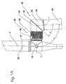
- Fig. 1 A shows a principle according to the invention for the protection of wind turbines by extreme wind loads damage caused explanatory schematic representation using a two-part head carrier 20.
- the head support 20 consists of two separate, independent elements 22, 24 which are connected in a pivoting plane 30 such that one element 22 is pivotable against the other element 24.
- the element 24 is connected to the tower 26 of the wind turbine via a vertical bearing 54.
- the element 22 is connected to the energy conversion unit 28.
- the energy conversion unit 28 consists in this preferred example of a rotor shaft 14 which is mounted in a rotor bearing, not shown, a gear 50 and a generator 52.
- the energy conversion unit 28 may also consist only of a rotor bearing and a generator 52.
- the pivot plane 30, in which the two elements 22, 24 are pivotable in the example shown, is formed in the present case by the bisecting line between the at least approximately horizontally oriented rotor axis x and the vertical tower axis y.
- the arrangement of the two axes x, y is chosen so that they intersect in the pivoting plane 30. This ensures that the rotor axis x is aligned with the tower axis y in the second position.
- the elements 22, 24 do not have to be identical, but rather may also be designed differently, as long as it is ensured that the element 22 can pivot on the element 24.
- the angle ⁇ between the tower axis y and the rotor axis x in the range 90 ° to 98 °. This results in an advantageous angle ⁇ for the pivoting plane 30 of 45 ° to 49 °.
- the Fig. 1B shows the wind turbine in the second position and a rotation of the element 22 relative to the element 24 by 180 °.
- the rotor 18 of the wind turbine Since the element 22 carries as part of a nacelle of a wind turbine, the rotor 18 of the wind turbine, the rotor 18 is rotated by rotation of the element 22 from a first position, which is usually taken for energy, in a second position in which the blade longitudinal axis z the blades attached to the rotor 18 32 are no longer aligned in an at least approximately vertical plane, but at least approximately horizontally (helicopter position).
- the rotor 18 of the wind energy installation according to the invention is a single-blade rotor 18 having a rotor hub 12, a single rotor blade 32 and a rotor blade counterweight 16.
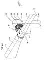
- Fig. 2 clarifies the explanation by means of Fig. 1 Employed considerations in the form of a particularly preferred embodiment of an offshore wind turbine 10 with a single-blade rotor 18.
- the offshore wind turbine 10 consists of a foundation mounted on a tower 26 and a gondola arranged thereon, which - Fig. 1 shown - consists of two elements 22, 24 and the energy conversion unit 28, wherein the element 24 is connected to the tower 26 of the wind turbine.
- the element 24 is preferably rotatably connected to the tower 26 via a vertical bearing 54 in order to align the rotor axis x against the mean wind direction can.
- the element 18 carrying the rotor 18 is pivotably connected to the element 24 in the pivoting plane 30.
- the rotor 18 of the wind power plant according to the invention is in a first position for energy production in Fig. 2A occupy the position shown, so that the rotor axis x is aligned approximately horizontally.
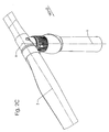
- the rotor 18 is first braked in a horizontal blade position, then the element 22 is analogous to that in Fig. 1 pivoted example with respect to the element 24, so that the rotor 18 from the in Fig. 2A shown first position in the in Fig. 2C shown second position, in the example shown, the one rotor blade 32 of the rotor 18 was also spent in leeward position relative to the tower.
- the one rotor blade in a typhoon can no longer be traversed transversely to the blade longitudinal axis z. Rather, the rotor 18 is supplied only from the side of the counterweight 16 along the blade longitudinal axis z. Due to the free rotatability of the rotor 18 about the rotor axis x, the rotor blade 32 will always track this direction when the wind direction changes, so that the rotor blade 32 can never be flown across transversely to the blade longitudinal axis z and thus the destructive flow is avoided.
- the Fig. 2B shows an intermediate position after about 90 ° pivoting.
- the wind power plant according to the invention comprises at least one sensor for detecting the wind speed, wherein particularly preferably a control is provided, the braking of the rotor 18 preferably in horizontal blade position and then the pivoting of the element 22 from the first position in the second position causes.
- a control is provided, the braking of the rotor 18 preferably in horizontal blade position and then the pivoting of the element 22 from the first position in the second position causes.
- Fig. 3 shows the pivot bearing which is arranged in the pivoting plane 30 in the embodiment as a plain bearing (A) and with a ball slewing ring (B).
- the element 24 is equipped with three sliding bearing elements 34 for receiving the axial and radial loads to be transmitted. These are braced via the element 22 and the clamping plate 36 with the screws 44.
- the clamping plate 36 is at the. Inside equipped with a toothing. In this internal toothing, the pinion 38 engages that via the gear 40 and the drive motor 42, the rotation of the element 22 relative to the element 24 allows.
- the transmission 40 is above the gear carrier 56 with the element 24th firmly connected. For weather protection of the slide bearing elements 22 and 24 are sealed with the seal 46 to the outside.
- the Fig. 3B shows the schematic structure of a pivot bearing with a ball pivot connection 48.
- the two pivot bearing rings with the elements 22, 24 are connected.
- a sealing element 46 also protects the bearing unit from external weather influences.
- the drive unit consisting of gear 40 and drive motor 42, has the same structure as in the plain bearing, wherein preferably the required internal toothing is attached to the inner ring of the ball pivot connection.
- the pivot bearing must have at least two limit switches for detecting the first and the second position to turn off the drive motor 42 accordingly or to be able to reverse the direction of rotation of the drive motor 42.
- the system can be equipped with an emergency generator or a battery storage that provide enough energy to perform the pivoting movement.
- These energy-storing means are preferably set up in such a way that they are charged during the ongoing operation of the wind energy plant in order to ensure the energy supply of the at least one drive motor 42 during the switch-off process.
Landscapes
- Engineering & Computer Science (AREA)
- Life Sciences & Earth Sciences (AREA)
- Sustainable Development (AREA)
- Sustainable Energy (AREA)
- Chemical & Material Sciences (AREA)
- Combustion & Propulsion (AREA)
- Mechanical Engineering (AREA)
- General Engineering & Computer Science (AREA)
- Power Engineering (AREA)
- Wind Motors (AREA)
Claims (7)
- Centrale à énergie éolienne (10) avec une tour verticale (26) et un rotor (18), présentant au moins une pale de rotor (32) et fixé sur la tour (26) ; rotor avec un axe à orientation horizontale et une unité de conversion de l'énergie (28), la centrale à énergie éolienne
caractérisée par le fait
qu'un palier de pivotement, dont le niveau de pivotement (30) se situe entre l'axe du rotor (x), à orientation horizontale, et l'axe de la tour (y), à orientation perpendiculaire, où l'axe du rotor (x) et l'axe de la tour (y) se coupent dans le niveau de pivotement (30), et
au moins un moteur (42) pour le pivotement du rotor (18) ensemble avec l'unité de conversion de l'énergie (28) à partir d'une première position, dans laquelle l'axe du rotor (x) est orienté horizontalement, vers une deuxième position, dans laquelle l'axe du rotor (x) est orienté verticalement. - Centrale à énergie éolienne (10) selon revendication 1, caractérisée en ce que le niveau de pivotement dans la bissectrice se situe entre l'axe du rotor (x) dans la première position et l'axe de la tour (y) à orientation perpendiculaire.
- Centrale à énergie éolienne (10) selon l'une des revendications précédentes, caractérisée par le fait qu'il existe des moyens, qui font pivoter le rotor (18) en cas de dépassement d'une vitesse du vent mesurée ou prédéfinie.
- Centrale à énergie éolienne (10) selon l'une des revendications précédentes, caractérisée par le fait, qu'une partie de l'énergie, obtenue lors de l'exploitation de l'installation, est amenée vers des moyens d'accumulation pour l'alimentation en énergie d'au moins un moteur (42).
- Centrale à énergie éolienne (10) selon l'une des revendications précédentes, caractérisée par le fait, que le roulement pivotant présente un interrupteur de fin de course, respectivement affecté à la première et la deuxième position.
- Centrale à énergie éolienne (10) selon l'une des revendications précédentes, caractérisée par le fait, que l'unité de conversion de l'énergie (28) présente un palier de rotor, une génératrice (52), un engrenage (50) et un frein.
- Centrale à énergie éolienne (10) selon l'une des revendications précédentes, caractérisée par le fait, que le rotor (18) est un rotor à une pale avec une pale de rotor (32) et un contrepoids (16).
Applications Claiming Priority (2)
| Application Number | Priority Date | Filing Date | Title |
|---|---|---|---|
| DE102007019513A DE102007019513B4 (de) | 2007-04-25 | 2007-04-25 | Windenergieanlage |
| PCT/DE2008/000682 WO2008131727A2 (fr) | 2007-04-25 | 2008-04-22 | Éolienne |
Publications (2)
| Publication Number | Publication Date |
|---|---|
| EP2140136A2 EP2140136A2 (fr) | 2010-01-06 |
| EP2140136B1 true EP2140136B1 (fr) | 2012-01-11 |
Family
ID=39777423
Family Applications (1)
| Application Number | Title | Priority Date | Filing Date |
|---|---|---|---|
| EP08757969A Not-in-force EP2140136B1 (fr) | 2007-04-25 | 2008-04-22 | Éolienne |
Country Status (8)
| Country | Link |
|---|---|
| US (1) | US8426993B2 (fr) |
| EP (1) | EP2140136B1 (fr) |
| KR (1) | KR101138525B1 (fr) |
| CN (1) | CN101707949B (fr) |
| AT (1) | ATE541122T1 (fr) |
| DE (1) | DE102007019513B4 (fr) |
| DK (1) | DK2140136T3 (fr) |
| WO (1) | WO2008131727A2 (fr) |
Families Citing this family (9)
| Publication number | Priority date | Publication date | Assignee | Title |
|---|---|---|---|---|
| DE102007012408A1 (de) * | 2007-03-15 | 2008-09-18 | Aerodyn Engineering Gmbh | Windenergieanlagen mit lastübertragenden Bauteilen |
| JPWO2010146654A1 (ja) * | 2009-06-16 | 2012-11-29 | 三菱重工業株式会社 | 風力発電装置 |
| GB201002558D0 (en) * | 2010-02-16 | 2010-03-31 | Wesby Philip | System and method for fluid power conversion |
| US8277184B2 (en) * | 2010-04-22 | 2012-10-02 | General Electric Company | Tilt adjustment system |
| DE102010055876A1 (de) * | 2010-12-24 | 2012-06-28 | Aerodyn Engineering Gmbh | Getriebe/Generator-Kupplung |
| GB2488803B (en) | 2011-03-09 | 2013-04-17 | Sway Turbine As | Wind turbine rotors and methods of mounting |
| DE102012000377A1 (de) * | 2012-01-12 | 2013-07-18 | Helmut Kümmerer | Windkraftanlage |
| CN110410270A (zh) * | 2019-08-02 | 2019-11-05 | 集美大学 | 一种防飓风装置 |
| WO2026008119A1 (fr) * | 2024-07-02 | 2026-01-08 | Benterki Mohamed Sadek | Turbine intelligente pour capter les courants |
Family Cites Families (18)
| Publication number | Priority date | Publication date | Assignee | Title |
|---|---|---|---|---|
| DE93426C (fr) * | ||||
| US2379857A (en) * | 1944-05-26 | 1945-07-10 | Bakke Olaf | Wind wheel generator |
| DE3201199A1 (de) * | 1982-01-16 | 1983-07-28 | Bernd Ing. Krieg (grad.), 2000 Hamburg | Drehkopf fuer windraeder mit einrichtung zur sturmsicherung und leistungsregelung |
| US4561826A (en) * | 1983-03-10 | 1985-12-31 | Taylor Derek A | Vertical axis wind turbines |
| US4767939A (en) * | 1987-06-09 | 1988-08-30 | Calley David G | Wind driven electric current producer |
| FI95960C (fi) * | 1993-06-23 | 1996-04-10 | Kari Rajalahti | Menetelmä ja laite tuulivoimalan turvapysäytystä varten |
| EP0709571A3 (fr) | 1994-10-25 | 1996-12-11 | Autoflug Energietech Gmbh | Position de repos à faible charge pour éolienne |
| US5518370A (en) * | 1995-04-03 | 1996-05-21 | Duracraft Corporation | Portable electric fan with swivel mount |
| US5746576A (en) * | 1996-10-15 | 1998-05-05 | World Power Technologies, Inc. | Wind energy conversion device with angled governing mechanism |
| DE19717059C1 (de) * | 1997-04-23 | 1998-07-09 | Aerodyn Eng Gmbh | Verfahren zum Verbringen einer Windkraftanlage in eine Parkstellung |
| NL1009566C2 (nl) * | 1998-07-06 | 2000-01-10 | Lagerwey Windturbine B V | Windmolen met stormbeveiliging. |
| DE10010615A1 (de) * | 2000-03-03 | 2001-09-06 | Duerr Systems Gmbh | Roboter zum Beschichten oder Behandeln von Werkstücken |
| DE10058076C2 (de) | 2000-11-23 | 2003-06-12 | Aloys Wobben | Verfahren zur Steuerung einer Windenergieanlage |
| BR0207714B1 (pt) * | 2001-12-28 | 2011-05-17 | turbina eólica do tipo contra o vento e método de operação da mesma. | |
| CH695790A5 (de) * | 2002-01-11 | 2006-08-31 | Paul Rosenich | Windkraftanlage. |
| EP1340910A1 (fr) * | 2002-02-28 | 2003-09-03 | Enel Green Power S.p.A. | Eolienne à aimants permanents et regulation de celle-ci. |
| US7095129B2 (en) * | 2004-06-30 | 2006-08-22 | General Electric Company | Methods and apparatus for rotor load control in wind turbines |
| US7352075B2 (en) * | 2006-03-06 | 2008-04-01 | General Electric Company | Methods and apparatus for controlling rotational speed of a rotor |
-
2007
- 2007-04-25 DE DE102007019513A patent/DE102007019513B4/de not_active Expired - Fee Related
-
2008
- 2008-04-22 EP EP08757969A patent/EP2140136B1/fr not_active Not-in-force
- 2008-04-22 US US12/532,559 patent/US8426993B2/en not_active Expired - Fee Related
- 2008-04-22 AT AT08757969T patent/ATE541122T1/de active
- 2008-04-22 WO PCT/DE2008/000682 patent/WO2008131727A2/fr not_active Ceased
- 2008-04-22 CN CN200880013126.5A patent/CN101707949B/zh not_active Expired - Fee Related
- 2008-04-22 DK DK08757969.4T patent/DK2140136T3/da active
- 2008-04-22 KR KR1020097023330A patent/KR101138525B1/ko not_active Expired - Fee Related
Also Published As
| Publication number | Publication date |
|---|---|
| DK2140136T3 (da) | 2012-02-27 |
| DE102007019513B4 (de) | 2012-03-15 |
| US20100096855A1 (en) | 2010-04-22 |
| EP2140136A2 (fr) | 2010-01-06 |
| KR101138525B1 (ko) | 2012-04-25 |
| US8426993B2 (en) | 2013-04-23 |
| DE102007019513A1 (de) | 2008-10-30 |
| KR20090130202A (ko) | 2009-12-18 |
| WO2008131727A3 (fr) | 2009-04-09 |
| WO2008131727A2 (fr) | 2008-11-06 |
| ATE541122T1 (de) | 2012-01-15 |
| CN101707949B (zh) | 2015-02-11 |
| CN101707949A (zh) | 2010-05-12 |
Similar Documents
| Publication | Publication Date | Title |
|---|---|---|
| EP2140136B1 (fr) | Éolienne | |
| DE10205988B4 (de) | Windenergieanlage | |
| EP1339985B1 (fr) | Commande azimutale pour une eolienne en cas de tempete | |
| DE19717059C1 (de) | Verfahren zum Verbringen einer Windkraftanlage in eine Parkstellung | |
| DE102010031081A1 (de) | Windenergieanlage | |
| EP3265675B1 (fr) | Procédé pour faire fonctionner une éolienne | |
| EP2063109A2 (fr) | Procédé de commande d'une éolienne | |
| DE102011056980A1 (de) | Windkraftanlage | |
| DE102019100208A1 (de) | Vertikale Windenergieanlage | |
| WO2013167652A1 (fr) | Éolienne à arbre de rotor horizontal et à mât rotatif | |
| DE102012221289A1 (de) | Verfahren zum Betreiben einer Windenergieanlage und Windenergieanlage | |
| EP2657515A1 (fr) | Éolienne avec régulation du pas | |
| EP3221578B1 (fr) | Conception d'une éolienne | |
| EP2570655B1 (fr) | Dispositif de réglage actif d'une pale de (petite) éolienne | |
| EP1387954B1 (fr) | Eolienne a axe vertical | |
| DE102016014799A1 (de) | Turmkonstruktion für eine Windenergieanlage | |
| DE102009051117A1 (de) | Horizontalläufer-Turbine mit passiver Gierwinkel-Einstellvorrichtung | |
| DE102018113760A1 (de) | Rotorlagergehäuse und Windenergieanlage mit Rotorlagergehäuse | |
| DE102010010208A1 (de) | Windkraftmaschine | |
| EP2249028B1 (fr) | Installation pour la production d'électricité à partir d'un écoulement de fluide | |
| DE202020000307U1 (de) | Vertikale Windenergieanlage | |
| EP2373886A2 (fr) | Position de repos d'une eolienne | |
| DE102011101443A1 (de) | Windkraftanlage mit verstellbaren Rotorblättern | |
| AT522627B1 (de) | Einrichtung zum Stellen und Regeln von Vertikalachs-Windturbinen mit planetenförmig umlaufenden Blättern | |
| EP1906010A1 (fr) | Eolienne avec système de protection en cas de tempête ou en cas de surrégime étant robuste, mécanique et sans entretien |
Legal Events
| Date | Code | Title | Description |
|---|---|---|---|
| PUAI | Public reference made under article 153(3) epc to a published international application that has entered the european phase |
Free format text: ORIGINAL CODE: 0009012 |
|
| 17P | Request for examination filed |
Effective date: 20090914 |
|
| AK | Designated contracting states |
Kind code of ref document: A2 Designated state(s): AT BE BG CH CY CZ DE DK EE ES FI FR GB GR HR HU IE IS IT LI LT LU LV MC MT NL NO PL PT RO SE SI SK TR |
|
| RIN1 | Information on inventor provided before grant (corrected) |
Inventor name: SIEGFRIEDSEN, SOENKE |
|
| 17Q | First examination report despatched |
Effective date: 20100930 |
|
| GRAP | Despatch of communication of intention to grant a patent |
Free format text: ORIGINAL CODE: EPIDOSNIGR1 |
|
| DAX | Request for extension of the european patent (deleted) | ||
| GRAS | Grant fee paid |
Free format text: ORIGINAL CODE: EPIDOSNIGR3 |
|
| GRAA | (expected) grant |
Free format text: ORIGINAL CODE: 0009210 |
|
| AK | Designated contracting states |
Kind code of ref document: B1 Designated state(s): AT BE BG CH CY CZ DE DK EE ES FI FR GB GR HR HU IE IS IT LI LT LU LV MC MT NL NO PL PT RO SE SI SK TR |
|
| REG | Reference to a national code |
Ref country code: GB Ref legal event code: FG4D Free format text: NOT ENGLISH |
|
| REG | Reference to a national code |
Ref country code: CH Ref legal event code: EP |
|
| REG | Reference to a national code |
Ref country code: AT Ref legal event code: REF Ref document number: 541122 Country of ref document: AT Kind code of ref document: T Effective date: 20120115 |
|
| REG | Reference to a national code |
Ref country code: IE Ref legal event code: FG4D |
|
| REG | Reference to a national code |
Ref country code: DK Ref legal event code: T3 |
|
| REG | Reference to a national code |
Ref country code: DE Ref legal event code: R096 Ref document number: 502008006115 Country of ref document: DE Effective date: 20120308 |
|
| REG | Reference to a national code |
Ref country code: NL Ref legal event code: T3 |
|
| REG | Reference to a national code |
Ref country code: SE Ref legal event code: TRGR |
|
| PG25 | Lapsed in a contracting state [announced via postgrant information from national office to epo] |
Ref country code: SI Free format text: LAPSE BECAUSE OF FAILURE TO SUBMIT A TRANSLATION OF THE DESCRIPTION OR TO PAY THE FEE WITHIN THE PRESCRIBED TIME-LIMIT Effective date: 20120111 |
|
| LTIE | Lt: invalidation of european patent or patent extension |
Effective date: 20120111 |
|
| PG25 | Lapsed in a contracting state [announced via postgrant information from national office to epo] |
Ref country code: LT Free format text: LAPSE BECAUSE OF FAILURE TO SUBMIT A TRANSLATION OF THE DESCRIPTION OR TO PAY THE FEE WITHIN THE PRESCRIBED TIME-LIMIT Effective date: 20120111 Ref country code: IS Free format text: LAPSE BECAUSE OF FAILURE TO SUBMIT A TRANSLATION OF THE DESCRIPTION OR TO PAY THE FEE WITHIN THE PRESCRIBED TIME-LIMIT Effective date: 20120511 Ref country code: HR Free format text: LAPSE BECAUSE OF FAILURE TO SUBMIT A TRANSLATION OF THE DESCRIPTION OR TO PAY THE FEE WITHIN THE PRESCRIBED TIME-LIMIT Effective date: 20120111 Ref country code: NO Free format text: LAPSE BECAUSE OF FAILURE TO SUBMIT A TRANSLATION OF THE DESCRIPTION OR TO PAY THE FEE WITHIN THE PRESCRIBED TIME-LIMIT Effective date: 20120411 Ref country code: BG Free format text: LAPSE BECAUSE OF FAILURE TO SUBMIT A TRANSLATION OF THE DESCRIPTION OR TO PAY THE FEE WITHIN THE PRESCRIBED TIME-LIMIT Effective date: 20120411 |
|
| REG | Reference to a national code |
Ref country code: IE Ref legal event code: FD4D |
|
| PG25 | Lapsed in a contracting state [announced via postgrant information from national office to epo] |
Ref country code: GR Free format text: LAPSE BECAUSE OF FAILURE TO SUBMIT A TRANSLATION OF THE DESCRIPTION OR TO PAY THE FEE WITHIN THE PRESCRIBED TIME-LIMIT Effective date: 20120412 Ref country code: FI Free format text: LAPSE BECAUSE OF FAILURE TO SUBMIT A TRANSLATION OF THE DESCRIPTION OR TO PAY THE FEE WITHIN THE PRESCRIBED TIME-LIMIT Effective date: 20120111 Ref country code: PT Free format text: LAPSE BECAUSE OF FAILURE TO SUBMIT A TRANSLATION OF THE DESCRIPTION OR TO PAY THE FEE WITHIN THE PRESCRIBED TIME-LIMIT Effective date: 20120511 Ref country code: LV Free format text: LAPSE BECAUSE OF FAILURE TO SUBMIT A TRANSLATION OF THE DESCRIPTION OR TO PAY THE FEE WITHIN THE PRESCRIBED TIME-LIMIT Effective date: 20120111 Ref country code: PL Free format text: LAPSE BECAUSE OF FAILURE TO SUBMIT A TRANSLATION OF THE DESCRIPTION OR TO PAY THE FEE WITHIN THE PRESCRIBED TIME-LIMIT Effective date: 20120111 |
|
| PG25 | Lapsed in a contracting state [announced via postgrant information from national office to epo] |
Ref country code: CY Free format text: LAPSE BECAUSE OF FAILURE TO SUBMIT A TRANSLATION OF THE DESCRIPTION OR TO PAY THE FEE WITHIN THE PRESCRIBED TIME-LIMIT Effective date: 20120111 |
|
| BERE | Be: lapsed |
Owner name: AERODYN ENGINEERING G.M.B.H. Effective date: 20120430 |
|
| PG25 | Lapsed in a contracting state [announced via postgrant information from national office to epo] |
Ref country code: CZ Free format text: LAPSE BECAUSE OF FAILURE TO SUBMIT A TRANSLATION OF THE DESCRIPTION OR TO PAY THE FEE WITHIN THE PRESCRIBED TIME-LIMIT Effective date: 20120111 Ref country code: EE Free format text: LAPSE BECAUSE OF FAILURE TO SUBMIT A TRANSLATION OF THE DESCRIPTION OR TO PAY THE FEE WITHIN THE PRESCRIBED TIME-LIMIT Effective date: 20120111 Ref country code: RO Free format text: LAPSE BECAUSE OF FAILURE TO SUBMIT A TRANSLATION OF THE DESCRIPTION OR TO PAY THE FEE WITHIN THE PRESCRIBED TIME-LIMIT Effective date: 20120111 Ref country code: IE Free format text: LAPSE BECAUSE OF FAILURE TO SUBMIT A TRANSLATION OF THE DESCRIPTION OR TO PAY THE FEE WITHIN THE PRESCRIBED TIME-LIMIT Effective date: 20120111 |
|
| PLBE | No opposition filed within time limit |
Free format text: ORIGINAL CODE: 0009261 |
|
| STAA | Information on the status of an ep patent application or granted ep patent |
Free format text: STATUS: NO OPPOSITION FILED WITHIN TIME LIMIT |
|
| PG25 | Lapsed in a contracting state [announced via postgrant information from national office to epo] |
Ref country code: SK Free format text: LAPSE BECAUSE OF FAILURE TO SUBMIT A TRANSLATION OF THE DESCRIPTION OR TO PAY THE FEE WITHIN THE PRESCRIBED TIME-LIMIT Effective date: 20120111 Ref country code: IT Free format text: LAPSE BECAUSE OF FAILURE TO SUBMIT A TRANSLATION OF THE DESCRIPTION OR TO PAY THE FEE WITHIN THE PRESCRIBED TIME-LIMIT Effective date: 20120111 Ref country code: MC Free format text: LAPSE BECAUSE OF NON-PAYMENT OF DUE FEES Effective date: 20120430 |
|
| REG | Reference to a national code |
Ref country code: CH Ref legal event code: PL |
|
| 26N | No opposition filed |
Effective date: 20121012 |
|
| PG25 | Lapsed in a contracting state [announced via postgrant information from national office to epo] |
Ref country code: CH Free format text: LAPSE BECAUSE OF NON-PAYMENT OF DUE FEES Effective date: 20120430 Ref country code: BE Free format text: LAPSE BECAUSE OF NON-PAYMENT OF DUE FEES Effective date: 20120430 Ref country code: LI Free format text: LAPSE BECAUSE OF NON-PAYMENT OF DUE FEES Effective date: 20120430 |
|
| REG | Reference to a national code |
Ref country code: DE Ref legal event code: R097 Ref document number: 502008006115 Country of ref document: DE Effective date: 20121012 |
|
| PG25 | Lapsed in a contracting state [announced via postgrant information from national office to epo] |
Ref country code: ES Free format text: LAPSE BECAUSE OF FAILURE TO SUBMIT A TRANSLATION OF THE DESCRIPTION OR TO PAY THE FEE WITHIN THE PRESCRIBED TIME-LIMIT Effective date: 20120422 |
|
| PG25 | Lapsed in a contracting state [announced via postgrant information from national office to epo] |
Ref country code: MT Free format text: LAPSE BECAUSE OF FAILURE TO SUBMIT A TRANSLATION OF THE DESCRIPTION OR TO PAY THE FEE WITHIN THE PRESCRIBED TIME-LIMIT Effective date: 20120111 |
|
| PG25 | Lapsed in a contracting state [announced via postgrant information from national office to epo] |
Ref country code: TR Free format text: LAPSE BECAUSE OF FAILURE TO SUBMIT A TRANSLATION OF THE DESCRIPTION OR TO PAY THE FEE WITHIN THE PRESCRIBED TIME-LIMIT Effective date: 20120111 |
|
| PG25 | Lapsed in a contracting state [announced via postgrant information from national office to epo] |
Ref country code: LU Free format text: LAPSE BECAUSE OF NON-PAYMENT OF DUE FEES Effective date: 20120422 |
|
| REG | Reference to a national code |
Ref country code: AT Ref legal event code: MM01 Ref document number: 541122 Country of ref document: AT Kind code of ref document: T Effective date: 20130422 |
|
| PG25 | Lapsed in a contracting state [announced via postgrant information from national office to epo] |
Ref country code: HU Free format text: LAPSE BECAUSE OF FAILURE TO SUBMIT A TRANSLATION OF THE DESCRIPTION OR TO PAY THE FEE WITHIN THE PRESCRIBED TIME-LIMIT Effective date: 20080422 |
|
| PG25 | Lapsed in a contracting state [announced via postgrant information from national office to epo] |
Ref country code: AT Free format text: LAPSE BECAUSE OF NON-PAYMENT OF DUE FEES Effective date: 20130422 |
|
| REG | Reference to a national code |
Ref country code: FR Ref legal event code: PLFP Year of fee payment: 9 |
|
| REG | Reference to a national code |
Ref country code: FR Ref legal event code: PLFP Year of fee payment: 10 |
|
| REG | Reference to a national code |
Ref country code: FR Ref legal event code: PLFP Year of fee payment: 11 |
|
| REG | Reference to a national code |
Ref country code: DE Ref legal event code: R082 Ref document number: 502008006115 Country of ref document: DE Representative=s name: BOEHMERT & BOEHMERT ANWALTSPARTNERSCHAFT MBB -, DE Ref country code: DE Ref legal event code: R081 Ref document number: 502008006115 Country of ref document: DE Owner name: AERODYN CONSULTING SINGAPORE PTE LTD, SG Free format text: FORMER OWNER: AERODYN ENGINEERING GMBH, 24768 RENDSBURG, DE Ref country code: DE Ref legal event code: R082 Ref document number: 502008006115 Country of ref document: DE Representative=s name: LOBEMEIER, MARTIN LANDOLF, DR., DE |
|
| PGFP | Annual fee paid to national office [announced via postgrant information from national office to epo] |
Ref country code: NL Payment date: 20180418 Year of fee payment: 11 |
|
| PGFP | Annual fee paid to national office [announced via postgrant information from national office to epo] |
Ref country code: DK Payment date: 20180418 Year of fee payment: 11 |
|
| PGFP | Annual fee paid to national office [announced via postgrant information from national office to epo] |
Ref country code: FR Payment date: 20180420 Year of fee payment: 11 |
|
| PGFP | Annual fee paid to national office [announced via postgrant information from national office to epo] |
Ref country code: SE Payment date: 20180418 Year of fee payment: 11 |
|
| PGFP | Annual fee paid to national office [announced via postgrant information from national office to epo] |
Ref country code: GB Payment date: 20180418 Year of fee payment: 11 |
|
| REG | Reference to a national code |
Ref country code: DE Ref legal event code: R082 Ref document number: 502008006115 Country of ref document: DE Representative=s name: LOBEMEIER, MARTIN LANDOLF, DR., DE |
|
| REG | Reference to a national code |
Ref country code: DK Ref legal event code: EBP Effective date: 20190430 |
|
| REG | Reference to a national code |
Ref country code: SE Ref legal event code: EUG |
|
| REG | Reference to a national code |
Ref country code: NL Ref legal event code: MM Effective date: 20190501 |
|
| GBPC | Gb: european patent ceased through non-payment of renewal fee |
Effective date: 20190422 |
|
| PG25 | Lapsed in a contracting state [announced via postgrant information from national office to epo] |
Ref country code: GB Free format text: LAPSE BECAUSE OF NON-PAYMENT OF DUE FEES Effective date: 20190422 Ref country code: NL Free format text: LAPSE BECAUSE OF NON-PAYMENT OF DUE FEES Effective date: 20190501 Ref country code: SE Free format text: LAPSE BECAUSE OF NON-PAYMENT OF DUE FEES Effective date: 20190423 |
|
| PG25 | Lapsed in a contracting state [announced via postgrant information from national office to epo] |
Ref country code: DK Free format text: LAPSE BECAUSE OF NON-PAYMENT OF DUE FEES Effective date: 20190430 |
|
| PG25 | Lapsed in a contracting state [announced via postgrant information from national office to epo] |
Ref country code: FR Free format text: LAPSE BECAUSE OF NON-PAYMENT OF DUE FEES Effective date: 20190430 |
|
| PGFP | Annual fee paid to national office [announced via postgrant information from national office to epo] |
Ref country code: DE Payment date: 20210310 Year of fee payment: 14 |
|
| REG | Reference to a national code |
Ref country code: DE Ref legal event code: R119 Ref document number: 502008006115 Country of ref document: DE |
|
| PG25 | Lapsed in a contracting state [announced via postgrant information from national office to epo] |
Ref country code: DE Free format text: LAPSE BECAUSE OF NON-PAYMENT OF DUE FEES Effective date: 20221103 |