EP2140201B1 - Système de connexion rapide d'un appareil d'allumage à des électrodes d'un appareil ménager et son utilisation - Google Patents
Système de connexion rapide d'un appareil d'allumage à des électrodes d'un appareil ménager et son utilisation Download PDFInfo
- Publication number
- EP2140201B1 EP2140201B1 EP08719353.8A EP08719353A EP2140201B1 EP 2140201 B1 EP2140201 B1 EP 2140201B1 EP 08719353 A EP08719353 A EP 08719353A EP 2140201 B1 EP2140201 B1 EP 2140201B1
- Authority
- EP
- European Patent Office
- Prior art keywords
- casing
- contacts
- chimney
- frame element
- contact
- Prior art date
- Legal status (The legal status is an assumption and is not a legal conclusion. Google has not performed a legal analysis and makes no representation as to the accuracy of the status listed.)
- Not-in-force
Links
- 230000008878 coupling Effects 0.000 claims description 11
- 238000010168 coupling process Methods 0.000 claims description 11
- 238000005859 coupling reaction Methods 0.000 claims description 11
- 238000010411 cooking Methods 0.000 claims description 8
- 239000012777 electrically insulating material Substances 0.000 claims description 8
- 230000002093 peripheral effect Effects 0.000 claims description 5
- 238000000465 moulding Methods 0.000 claims description 4
- 239000000463 material Substances 0.000 claims description 3
- 239000004020 conductor Substances 0.000 claims description 2
- 230000000284 resting effect Effects 0.000 claims description 2
- NFLLKCVHYJRNRH-UHFFFAOYSA-N 8-chloro-1,3-dimethyl-7H-purine-2,6-dione 2-(diphenylmethyl)oxy-N,N-dimethylethanamine Chemical compound O=C1N(C)C(=O)N(C)C2=C1NC(Cl)=N2.C=1C=CC=CC=1C(OCCN(C)C)C1=CC=CC=C1 NFLLKCVHYJRNRH-UHFFFAOYSA-N 0.000 description 4
- 238000002788 crimping Methods 0.000 description 1
- 230000037431 insertion Effects 0.000 description 1
- 238000003780 insertion Methods 0.000 description 1
- 238000004519 manufacturing process Methods 0.000 description 1
- 230000013011 mating Effects 0.000 description 1
- 238000005476 soldering Methods 0.000 description 1
Images

Classifications
-
- F—MECHANICAL ENGINEERING; LIGHTING; HEATING; WEAPONS; BLASTING
- F23—COMBUSTION APPARATUS; COMBUSTION PROCESSES
- F23Q—IGNITION; EXTINGUISHING-DEVICES
- F23Q3/00—Igniters using electrically-produced sparks
- F23Q3/006—Details
-
- F—MECHANICAL ENGINEERING; LIGHTING; HEATING; WEAPONS; BLASTING
- F23—COMBUSTION APPARATUS; COMBUSTION PROCESSES
- F23Q—IGNITION; EXTINGUISHING-DEVICES
- F23Q3/00—Igniters using electrically-produced sparks
Definitions
- the present invention relates to a quick connection device and its use in an electronic gas lighting device, of the type intended to equip an electric household appliance, such as for example a cooking range, for determining the controlled lighting of the burners by supplying a high voltage to electrodes fixable to the cooking range, in order to connect the electrodes to the high-voltage outputs of the gas lighting device.
- an electronic gas lighting device including a casing formed by electrically insulating material provided with a plurality of high-voltage outputs each defined by a chimney-like housing, integrally obtained with the casing and carrying a corresponding high-voltage contact therein, e.g. a male faston connector.
- each contact in the chimney-like housings must be connected, by means of an electric wire, to a corresponding spark generating electrode, fixable to the cooking range at a burner.
- the electric wire is pre-wired, e.g.
- the above-described known device are more than satisfactory.
- the assembly times of the electric wires on the high-voltage outputs of the gas lighting devices are relatively long; furthermore, due to possible incorrect manoeuvres by the assembly operator, the male and female faston connectors may not be correctly coupled, causing even possible deformations of the same.
- the electric household appliance manufacturer cannot automatically assemble the wires onto the high-voltage outputs of the gas lighting device, because it would be essentially impossible to ensure the correct, simultaneous positioning of all male contacts with all female contacts.
- the invention relates to a high-voltage output quick connection device in an electronic gas lighting device with corresponding spark generating electrodes fastenable onto an electric household appliance, as defined in claim 1.
- the present invention also relates to the use of such a connector in an electronic gas lighting device as defined in claim 4.
- the electronic gas lighting device comprises a cup-shaped casing, formed by an electrically insulating material; a plurality of high-voltage outputs carried by the casing and each comprising a chimney-like housing carried by the casing and also formed by an electrically insulating material and a first electric contact carried by the chimney-like housing and arranged therein; and a frame element integrally and protrudingly carrying, on a first face thereof intended in use to face the casing, a plurality of second contacts, in number equal to the high-voltage outputs present on the casing and adapted to couple with the first contacts within said chimney-like housings; the frame element being further provided on a second face thereof, opposite to the first, with a plurality of electric wires each connecting a second contact with a spark generating electrode fastenable to the household appliance; and with snapping fastening means to the casing peripherally arranged on the outside of the frame element, along at least one side of the same.
- Each chimney-like housing is provided with an open end for the reception of a corresponding second contact and carries therein a corresponding first contact mounted close to a bottom wall of the chimney-like housing, opposite to the open end, so as to remain away from the open end and well within the chimney-like housing.
- the frame element is integrally provided, on the first face thereof and for each second contact, with a longeron-shaped guide element adapted to slidingly couple, for the entire length thereof, within a corresponding chimney-like housing, through the open end of the same, to guide the second contact into electric coupling with the corresponding first contact arranged within the chimney-like housing.
- this being a pre-wireable device for subassemblies later reciprocally coupled with a single simple movement (the casing with the chimney-like housings and containing the electronics on one side and the frame element with the electric wires and the second contacts on the other) it allows the manufacturer to provide an entirely automatic assembly cycle.
- the contacts can be made in a non-traditional manner, e.g. as simple flat terminals, which are in use simply facing each other and arranged at a sufficiently small predetermined distance (thus not necessarily in reciprocal contact) into an insulated environment formed by the chimney-like housings.
- the aforesaid contacts indeed, being high-voltage contacts, may transmit electric current in the form of discharge with perforation of the dielectric constituted by the air between the facing contacts.
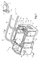
- numeral 1 indicates as a whole a gas lighting device for an electric household appliance, a cooking range 2 in this non-limiting illustrated embodiment, provided with a plurality of burners 3 (only one of which is shown for the sake of simplicity);
- the device 1 comprises a cup-shaped casing 5, formed by an electrically insulating material, e.g. by moulding of a synthetic plastic material, and a plurality of high-voltage outputs 8 carried by the casing 5 and each comprising ( figure 2 ) a chimney-like housing 9 carried by the casing 5 and also formed by an electrically insulating material and an electric contact 10 carried by the chimney-like housing 9 and arranged therein.
- the gas lighting device 1 further comprises a quick connection device 11 of the high-voltage outputs 8 of the casing 5 to corresponding spark generating electrodes 12, also belonging to the gas lighting device 1 as a whole and fixable in use in a known manner, each close to a corresponding burner 3 on the cooking range 2 in order to be able to control the lighting in a known manner.
- the device 11 comprises a frame element 15 integrally and protrudingly carrying, on a first face 16 thereof ( figure 2 ) intended in use to face the casing 5, a plurality of second contacts 18, in number equal to the high-voltage outputs 8 present on the casing 5 and adapted to couple with contacts 10 inside the chimney-like housings 9.
- the frame element 15 is further provided, on a second face 19 thereof, opposite to the face 16, with a plurality of electric wires 20 each connecting a contact 18 with a spark generating electrode 12.
- the chimney-like housings 9 are made as a non-integral part of the casing 5, but instead are independent elements, arranged at least in part within the casing 5 (in which they are embedded and blocked in use by means of resining) and so as to overhangingly protrude, with corresponding open ends 21 thereof, through a mouth 22 of the cup-shaped casing 5, but only immediately over a peripheral edge 23 of the mouth 22; in such a case, the frame element 15 is defined by a plate-shaped lid adapted to couple by resting on the open ends 21 protruding from the mouth 22 to close the same and essentially cover the mouth 22, so as to protect the resining underneath which fills the casing 5 in use.
- the quick connection device 11 is completed by snapping fastening means 30 of the frame element 15 to the casing 5 peripherally arranged on the outside of the frame element 15, along at least one side of the same.
- each chimney-like housing 9 allows the reception in the same of a corresponding contact 18 for coupling with the contact 10, because the latter is mounted close to (onto, in this case) a bottom wall 34 ( figure 2 ) of the chimney-like housing 9, opposite to the open end 21, so as to remain away from the open end 21 and well within the chimney-like housing 9.
- the frame element 15 is integrally provided on the face 16 and perpendicularly protrudingly with respect to the same, for each existing contact 18, with a longeron-shaped guide element 36 ( figure 2 ) adapted to slidingly couple, for the entire length thereof, within a corresponding chimney-like housing 9, through the open end 21 of the same, to guide the contact 18 it carries into electric coupling with the corresponding contact 10 arranged within the chimney-like housing 9.
- the frame element 15 and the longeron-shaped guide elements 36 are formed in a one-piece single part by moulding an electrically non-conducting material, in this case a synthetic plastic material; the contacts 18 are also carried by, and embedded at least in part in, the longeron-shaped guide elements 36, so as to be protrudingly carried with respect to the face 16, each at a free end 40 ( figure 2 ) of a corresponding longeron-shaped guide element 36.
- the contacts 18 are further fastened and connected in a pre-wired manner with the spark generating electrodes 12 by means of the electric wires 20, the opposite ends of which are electrically and mechanically connected, in a pre-wired manner, to the contacts 18 on one side and to the electrodes 12 on the other, e.g. by crimping or soldering.
- the ends of the wires 20 are, on the end of the contacts 18 (i.e. on the opposite side of the electrodes 12), also at least in part embedded in the longeron-shaped guide elements 36 along with the contacts 18.
- the longeron-shaped guiding elements 36 are shaped so as to display a peripheral profile mating with the inner peripheral profile of the chimney-like housings 9, so that the outer side surfaces thereof cooperate in use with the inner side surfaces of the chimney-like elements 9; in this manner, a firm mechanical coupling is obtained between casing 5 and frame element 15 already with the simple insertion of the longeron-shaped guide elements 36 in the housings 9 arranged for them, coupling later completed by the fastening means 30.
- the snapping fastening means 30 to the casing 5 may be simplified and consisting of a single elastic fin 41 (instead of, for example, of a plurality of fins) arranged on one single side 42 of the frame element 15, between a pair of longeron-shaped guide elements 36, overhangingly protruding from the frame element 15 with respect to both faces 16 and 19, perpendicularly to the same and provided towards the casing 5 with a fastening end 43, in this case slot-shaped, adapted to snappingly couple with a corresponding peg 45, in this case tooth-shaped, integrally obtained with the casing 5 on a side wall 46 of the same.
- the contacts 10 are defined by corresponding flat terminals carried just at the bottom walls 34 of the chimney-like housings 9, parallelly to the same and, similarly, the contacts 18 are also defined by corresponding flat terminals (diagrammatically indicated by a dashed line) of size either equal to or lower than that of the flat terminals defining the contacts 10, directly carried at the free ends 40 of the longeron-shaped guide elements 36, intended in use to face the bottom walls 34 of the chimney-like housings 9, as shown in figure 2 .
- the frame element 15 is provided with abutting means 50 cooperating with the casing 5 (in this case, with the peripheral edge 23 delimiting the mouth 22) for positioning the contacts 18 with the corresponding ends 40 at a distance D predetermined by the contacts 10 with the corresponding bottom walls 34, and facing the latter.
- the described gas lighting device 1 is completed by known snapping fastening means 70 to the cooking range 2, shown only in part for simplicity.
- the positioning of the contacts 10 simply close to the contacts 18, without even needing a direct physical contact, being high-voltage operating contacts, however allows the necessary passage of electric current for supplying the sparking on the electrodes 12, also because the current passage occurs in a closed and insulated environment, delimited between the bottom walls 34, the ends 40 and the side walls of the housings 9.
Landscapes
- Engineering & Computer Science (AREA)
- Chemical & Material Sciences (AREA)
- Combustion & Propulsion (AREA)
- Mechanical Engineering (AREA)
- General Engineering & Computer Science (AREA)
- Connector Housings Or Holding Contact Members (AREA)
- Physical Or Chemical Processes And Apparatus (AREA)
- Arrangement Of Elements, Cooling, Sealing, Or The Like Of Lighting Devices (AREA)
Claims (10)
- Dispositif de connexion rapide pour sortie à haute tension (11) pour coupler à des sorties à haute tension (8) d'un dispositif électronique d'allumage de gaz (1) des électrodes de génération d'étincelle correspondantes pouvant être attachées sur un appareil domestique électrique, dans lequel il comprend un élément de cadre (13) portant de façon intégrale et saillante, sur une première face (16) de celui-ci destinée lors de l'utilisation à faire face à une enceinte (5) du dispositif d'allumage de gaz (1), une pluralité de contacts (18), en nombre égal aux sorties à haute tension (8) et sur une deuxième face (19) de celui-ci, opposée à la première, une pluralité de fils électriques (20) connectant chacun d'une manière pré-câblée un desdits contacts (18) à l'une desdites électrodes de génération d'étincelle (12);
caractérisé en ce que l'élément de cadre (15) est pourvu de moyens de butée (50) qui coopèrent lors de l'utilisation avec l'enceinte (5) pour positionner lesdits contacts (18) à une distance prédéterminée (D) par des contacts correspondants (10) portés par l'enceinte (5), mais en face des contacts correspondants (10) portés par l'enceinte (5). - Dispositif selon la revendication 1, caractérisé en ce que ledit élément de cadre (15) est intégralement pourvu, sur ladite première face (16) et pour chacun desdits contacts (18), d'un élément de guide en forme de longeron (36) configuré de manière à être apte à se coupler par glissement lors de l'utilisation, sur la totalité de sa longueur, à l'intérieur d'un boîtier correspondant en forme de cheminée (9) du dispositif d'allumage de gaz (1), définissant une dite sortie à haute tension correspondante (8), chaque contact (18) étant porté par une extrémité libre (40) d'un élément de guidage correspondant (36), au moins en partie incorporé à l'intérieur de celui-ci de concert avec une extrémité dudit fil électrique (20), opposée à l'électrode correspondante (12), attachée et pré-câblée au contact (18).
- Dispositif selon la revendication 1 ou 2, caractérisé en ce que ledit élément de cadre (15) et lesdits éléments de guidage en forme de longeron (36) sont formés en une partie d'une seule pièce en moulant un matériau électriquement non conducteur, et sont de préférence constitués d'un matériau plastique synthétique.
- Utilisation d'un dispositif de connexion rapide pour sortie à haute tension (11) selon l'une quelconque des revendications 1 à 3 dans un dispositif électronique d'allumage de gaz (1) pour un appareil domestique électrique, en particulier un fourneau de cuisson (2), du type comprenant: une enceinte en forme de coupe (5), constituée d'un matériau électriquement isolant; et une pluralité de sorties à haute tension (8) portées par l'enceinte et comprenant chacune un boîtier en forme de cheminée (9) porté par l'enceinte et également constitué d'un matériau électriquement isolant et un premier contact électrique (10) porté par le boîtier en forme de cheminée et agencé dans celui-ci; dans lequel ledit dispositif électronique d'allumage de gaz est conçu de manière à comprendre en outre un élément de cadre (15) portant de façon intégrale et saillante, sur une première face (16) de celui-ci destinée lors de l'utilisation à faire face à l'enceinte (5), une pluralité de seconds contacts (18), en nombre égal aux sorties à haute tension (8) présentes sur l'enceinte et adaptés pour se coupler aux premiers contacts (10) à l'intérieur desdits boîtiers en forme de cheminée (9); l'élément de cadre (15) étant en outre pourvu sur une deuxième face (19) de celui-ci, opposée à la première, d'une pluralité de fils électriques (20) connectant chacun un second contact (18) à une électrode de génération d'étincelle (12) qui peut être attachée à l'appareil domestique; et de moyens de fixation par encliquetage (30) à l'enceinte (5) agencés de façon périphérique sur l'extérieur de l'élément de cadre (15), le long d'au moins un côté de celui-ci; caractérisée en ce que l'élément de cadre (15) est pourvu de moyens de butée (50) qui coopèrent avec l'enceinte (5) pour positionner les seconds contacts (18) à une distance (D) prédéterminée par les premiers contacts (10), mais face à ceux-ci.
- Utilisation selon la revendication 4, caractérisée en ce que lesdits boîtiers en forme de cheminée (9) sont agencés au moins en partie à l'intérieur de ladite enceinte (5) et de manière à faire saillie, avec les extrémités ouvertes correspondantes (21) de ceux-ci, de façon suspendue à travers une bouche (22) de l'enceinte en forme de coupe, mais uniquement immédiatement au-dessus d'un bord périphérique (23) de ladite bouche; ledit élément de cadre (15) étant défini par un couvercle en forme de plaque apte à être couplé en reposant sur lesdites extrémités ouvertes (21) faisant saillie à partir de la bouche afin de fermer celles-ci et de couvrir essentiellement ladite bouche.
- Utilisation selon la revendication 4 ou 5, caractérisée en ce que chacun desdits boîtiers en forme de cheminée (9) présente une extrémité ouverte (21) pour la réception d'un second contact correspondant (18) et porte intérieurement dans celui-ci un premier contact correspondant (10) monté à proximité d'une paroi inférieure (34) du boîtier en forme de cheminée, opposée à ladite extrémité ouverte (21), de manière à rester à l'écart de l'extrémité ouverte et bien à l'intérieur du boîtier en forme de cheminée.
- Utilisation selon la revendication 6, caractérisée en ce que ledit élément de cadre (15) est intégralement pourvu sur ladite première face (16) et pour chaque second contact (18) d'un élément de guidage en forme de longeron (36) apte à se coupler par glissement, sur la totalité de sa longueur, à l'intérieur dudit boîtier en forme de cheminée correspondant (9) à travers l'extrémité ouverte (21) de celui-ci, afin de guider le second contact (18) dans un couplage électrique avec le premier contact correspondant (10) agencé à l'intérieur du boîtier en forme de cheminée (9).
- Utilisation selon la revendication 7, caractérisée en ce que ledit élément de cadre (15) et lesdits éléments de guidage (36) pour les seconds contacts sont formés en une partie d'une seule pièce en moulant un matériau électriquement isolant; lesdits seconds contacts (18) étant portés incorporés au moins en partie à l'intérieur desdits éléments de guidage (36).
- Utilisation selon la revendication 7 ou 8, caractérisée en ce que lesdits moyens de fixation par encliquetage (30) à l'enceinte sont constitués d'une seule ailette élastique (41) agencée sur un côté (42) de l'élément de cadre (15), entre une paire desdits éléments de guidage (36) pour les seconds contacts, faisant saillie en suspension à partir de l'élément de cadre par rapport à la fois à la première face et à la deuxième face (16; 19) de l'élément de cadre, perpendiculairement à celui-ci et pourvu en direction de l'enceinte (5) d'une extrémité de fixation (43) apte à se coupler par encliquetage à un ancrage correspondant (45) formé intégralement sur une paroi latérale (46) de celle-ci.
- Utilisation selon l'une quelconque des revendications 7 à 9, caractérisée en ce que lesdits premiers contacts (10) sont définis par des premières bornes plates correspondantes portées juste aux parois inférieures (34) des boîtiers en forme de cheminée, parallèlement à celles-ci; lesdits seconds contacts (18) étant définis par des secondes bornes plates correspondantes, de taille soit égale soit inférieure à celle des premières bornes plates, portées directement à des extrémités libres respectives (40) des éléments de guidage en forme de longeron (36) de l'élément de cadre, prévues lors de l'utilisation pour faire face auxdites parois inférieures (34) des boîtiers en forme de cheminée (9).
Applications Claiming Priority (2)
| Application Number | Priority Date | Filing Date | Title |
|---|---|---|---|
| IT000216A ITTO20070216A1 (it) | 2007-03-26 | 2007-03-26 | Dispositivo accendigas elettronico per un elettrodomestico, in particolare un piano di cottura, con sistema di connessione rapida agli elettrodi |
| PCT/IB2008/000683 WO2008117157A2 (fr) | 2007-03-26 | 2008-03-24 | Appareil d'allumage de gaz pour appareil ménager électrique, en particulier du type cuisinière, ayant un système de connexion rapide à des électrodes |
Publications (2)
| Publication Number | Publication Date |
|---|---|
| EP2140201A2 EP2140201A2 (fr) | 2010-01-06 |
| EP2140201B1 true EP2140201B1 (fr) | 2015-08-12 |
Family
ID=39616390
Family Applications (1)
| Application Number | Title | Priority Date | Filing Date |
|---|---|---|---|
| EP08719353.8A Not-in-force EP2140201B1 (fr) | 2007-03-26 | 2008-03-24 | Système de connexion rapide d'un appareil d'allumage à des électrodes d'un appareil ménager et son utilisation |
Country Status (5)
| Country | Link |
|---|---|
| US (2) | US20100055630A1 (fr) |
| EP (1) | EP2140201B1 (fr) |
| CN (1) | CN101595345B (fr) |
| IT (1) | ITTO20070216A1 (fr) |
| WO (1) | WO2008117157A2 (fr) |
Citations (1)
| Publication number | Priority date | Publication date | Assignee | Title |
|---|---|---|---|---|
| EP0147956A2 (fr) * | 1983-12-28 | 1985-07-10 | Amp Incorporated | Connecteur avec des moyens pour assurer un bon ajustage des contacts |
Family Cites Families (19)
| Publication number | Priority date | Publication date | Assignee | Title |
|---|---|---|---|---|
| ES187268Y (es) * | 1972-12-29 | 1974-08-16 | Industrias Copreci, S, C. I. | Encendedor electronico temporizado para aparatos de gas. |
| US3950124A (en) * | 1975-04-10 | 1976-04-13 | Berry Fred M | Burner ignitor arrangement |
| US4386385A (en) * | 1980-08-07 | 1983-05-31 | Eaton Corporation | Spark electrode assembly |
| US5425631A (en) * | 1994-08-11 | 1995-06-20 | Eaton Corporation | Controlling a gaseous fuel burner and control valve therefor |
| US5937846A (en) * | 1995-11-21 | 1999-08-17 | Robertshaw Controls Company | Fluid control assembly |
| GB2337877B (en) * | 1998-05-28 | 2000-10-04 | Yazaki Corp | Connector fitting structure |
| IT1303090B1 (it) * | 1998-07-28 | 2000-10-30 | Miller Europe Spa | Dispositivo accendigas elettronico integrato con una morsettiera. |
| IT1303089B1 (it) * | 1998-07-28 | 2000-10-30 | Miller Europe Spa | Dispositivo accendigas elettronico. |
| IT1303088B1 (it) * | 1998-07-28 | 2000-10-30 | Miller Europe Spa | Dispositivo accendigas elettronico ad attacco rapido. |
| US6478609B1 (en) * | 2000-10-02 | 2002-11-12 | Tyco Electronics Corporation | Strain relief assembly |
| ITTO20030278A1 (it) * | 2003-04-11 | 2004-10-12 | Itw Ind Components Srl | Dispositivo accendigas elettrico realizzabile senza vincoli nel numero di terminali di uscita e metodo per la sua fabbricazione. |
| US7241183B2 (en) * | 2005-01-31 | 2007-07-10 | Delphi Technologies, Inc. | Electrical connector with integrated terminal position assurance and wire cover |
| US7497728B2 (en) * | 2005-02-15 | 2009-03-03 | Spx Corporation | Panel mount electrical connector in a burner enclosure apparatus and method |
| TR200500747A1 (tr) * | 2005-03-04 | 2006-10-26 | Amaç Elektroni̇k Gaz Ateşleme Si̇stemleri̇ San. Ve Ti̇c. Ltd. Şti̇. | Soketli kapakta bütünleştirilmiş gaz ateşleme cihazı. |
| ITTO20060168A1 (it) * | 2006-03-07 | 2007-09-08 | Itw Ind Components Srl | Dispositivo di accensione e controllo di un fuoco in un elettrodomestico, in particolare un piano barbecue |
| ITTO20060502A1 (it) * | 2006-07-10 | 2008-01-11 | Itw Ind Components Srl | Dispositivo di accensione di fuochi in un elettrodomestico, in particolare un piano cottura o barbecue |
| US7924546B2 (en) * | 2006-10-13 | 2011-04-12 | R.W. Beckett Corporation | Burner ignition controller and improved coil bobbin |
| US7390210B2 (en) * | 2006-11-08 | 2008-06-24 | Dsm&T Company Inc. | Electrical connector with high impact strength locking assemblies |
| DE102009043516A1 (de) | 2009-09-30 | 2011-04-07 | Tyco Electronics Amp Gmbh | Zweiteiliges Kontaktelement für Hochspannungssteckverbinder |
-
2007
- 2007-03-26 IT IT000216A patent/ITTO20070216A1/it unknown
-
2008
- 2008-03-24 CN CN2008800033987A patent/CN101595345B/zh not_active Expired - Fee Related
- 2008-03-24 US US12/529,322 patent/US20100055630A1/en not_active Abandoned
- 2008-03-24 EP EP08719353.8A patent/EP2140201B1/fr not_active Not-in-force
- 2008-03-24 WO PCT/IB2008/000683 patent/WO2008117157A2/fr not_active Ceased
-
2014
- 2014-03-18 US US14/218,881 patent/US9383103B2/en active Active
Patent Citations (1)
| Publication number | Priority date | Publication date | Assignee | Title |
|---|---|---|---|---|
| EP0147956A2 (fr) * | 1983-12-28 | 1985-07-10 | Amp Incorporated | Connecteur avec des moyens pour assurer un bon ajustage des contacts |
Also Published As
| Publication number | Publication date |
|---|---|
| US20140199645A1 (en) | 2014-07-17 |
| US9383103B2 (en) | 2016-07-05 |
| US20100055630A1 (en) | 2010-03-04 |
| WO2008117157A2 (fr) | 2008-10-02 |
| CN101595345A (zh) | 2009-12-02 |
| WO2008117157A3 (fr) | 2008-11-27 |
| ITTO20070216A1 (it) | 2008-09-27 |
| EP2140201A2 (fr) | 2010-01-06 |
| CN101595345B (zh) | 2011-06-08 |
Similar Documents
| Publication | Publication Date | Title |
|---|---|---|
| JP7118675B2 (ja) | コンタクトキャリア、電気コンタクトユニット、および既製のケーブルを作製する方法 | |
| CN109414996B (zh) | 具有带有温度传感器的电路板的热耦合的电连接装置 | |
| KR101660093B1 (ko) | 전기 커넥터 | |
| US20070032109A1 (en) | Power supply with a changeable plug element | |
| US20120077355A1 (en) | Feeder Clamp | |
| CN105144502B (zh) | 车辆侧连接器 | |
| US7753734B2 (en) | Cable terminal device for transmitting electrical drive power | |
| KR20120130338A (ko) | 전자 부품 | |
| US10411387B2 (en) | Terminal | |
| CN113197353A (zh) | 电子雾化装置及其供电组件和支架组件 | |
| EP2760084B1 (fr) | Connecteur de câble | |
| CN106165189B (zh) | 配线模块 | |
| EP2140201B1 (fr) | Système de connexion rapide d'un appareil d'allumage à des électrodes d'un appareil ménager et son utilisation | |
| JP4837025B2 (ja) | プラグハウジング及び駆動電力伝送用電気プラグ | |
| US8575519B2 (en) | Electronic gas igniter device and integrated box-like terminal board featuring a cable clamp, in particular for electric household appliances | |
| US11929565B2 (en) | Interface for a printed circuit board | |
| KR20150107748A (ko) | 다극잭 및 그 제조방법과 전자기기 | |
| EP1073162B1 (fr) | Interrupteur avec prise d'entrée de tension alternative | |
| CA2255177C (fr) | Lampe a decharge a basse pression compacte | |
| JP2006098049A (ja) | 空気加熱器 | |
| US20230268695A1 (en) | Electrical plug connector | |
| CN110212345B (zh) | 差分连接器及弯式接触件的安装结构 | |
| EP1873873B1 (fr) | Dispositif de connexion électrique rapide et son utilisation pour neutraliser un excès de terminal de sortie de haute tension d'un allumoir à gaz électronique pour appareils électroménagers, en particulier une plaque de cuisson | |
| KR100909579B1 (ko) | 동축커넥터 | |
| CN106710917B (zh) | 按钮开关 |
Legal Events
| Date | Code | Title | Description |
|---|---|---|---|
| PUAI | Public reference made under article 153(3) epc to a published international application that has entered the european phase |
Free format text: ORIGINAL CODE: 0009012 |
|
| 17P | Request for examination filed |
Effective date: 20091026 |
|
| AK | Designated contracting states |
Kind code of ref document: A2 Designated state(s): AT BE BG CH CY CZ DE DK EE ES FI FR GB GR HR HU IE IS IT LI LT LU LV MC MT NL NO PL PT RO SE SI SK TR |
|
| 17Q | First examination report despatched |
Effective date: 20100507 |
|
| DAX | Request for extension of the european patent (deleted) | ||
| GRAP | Despatch of communication of intention to grant a patent |
Free format text: ORIGINAL CODE: EPIDOSNIGR1 |
|
| INTG | Intention to grant announced |
Effective date: 20150227 |
|
| GRAS | Grant fee paid |
Free format text: ORIGINAL CODE: EPIDOSNIGR3 |
|
| GRAA | (expected) grant |
Free format text: ORIGINAL CODE: 0009210 |
|
| AK | Designated contracting states |
Kind code of ref document: B1 Designated state(s): AT BE BG CH CY CZ DE DK EE ES FI FR GB GR HR HU IE IS IT LI LT LU LV MC MT NL NO PL PT RO SE SI SK TR |
|
| REG | Reference to a national code |
Ref country code: GB Ref legal event code: FG4D |
|
| REG | Reference to a national code |
Ref country code: CH Ref legal event code: EP |
|
| REG | Reference to a national code |
Ref country code: AT Ref legal event code: REF Ref document number: 742511 Country of ref document: AT Kind code of ref document: T Effective date: 20150815 |
|
| REG | Reference to a national code |
Ref country code: IE Ref legal event code: FG4D |
|
| REG | Reference to a national code |
Ref country code: DE Ref legal event code: R096 Ref document number: 602008039498 Country of ref document: DE |
|
| REG | Reference to a national code |
Ref country code: LT Ref legal event code: MG4D |
|
| REG | Reference to a national code |
Ref country code: AT Ref legal event code: MK05 Ref document number: 742511 Country of ref document: AT Kind code of ref document: T Effective date: 20150812 |
|
| REG | Reference to a national code |
Ref country code: NL Ref legal event code: MP Effective date: 20150812 |
|
| PG25 | Lapsed in a contracting state [announced via postgrant information from national office to epo] |
Ref country code: LT Free format text: LAPSE BECAUSE OF FAILURE TO SUBMIT A TRANSLATION OF THE DESCRIPTION OR TO PAY THE FEE WITHIN THE PRESCRIBED TIME-LIMIT Effective date: 20150812 Ref country code: GR Free format text: LAPSE BECAUSE OF FAILURE TO SUBMIT A TRANSLATION OF THE DESCRIPTION OR TO PAY THE FEE WITHIN THE PRESCRIBED TIME-LIMIT Effective date: 20151113 Ref country code: LV Free format text: LAPSE BECAUSE OF FAILURE TO SUBMIT A TRANSLATION OF THE DESCRIPTION OR TO PAY THE FEE WITHIN THE PRESCRIBED TIME-LIMIT Effective date: 20150812 Ref country code: FI Free format text: LAPSE BECAUSE OF FAILURE TO SUBMIT A TRANSLATION OF THE DESCRIPTION OR TO PAY THE FEE WITHIN THE PRESCRIBED TIME-LIMIT Effective date: 20150812 Ref country code: NO Free format text: LAPSE BECAUSE OF FAILURE TO SUBMIT A TRANSLATION OF THE DESCRIPTION OR TO PAY THE FEE WITHIN THE PRESCRIBED TIME-LIMIT Effective date: 20151112 |
|
| PG25 | Lapsed in a contracting state [announced via postgrant information from national office to epo] |
Ref country code: PL Free format text: LAPSE BECAUSE OF FAILURE TO SUBMIT A TRANSLATION OF THE DESCRIPTION OR TO PAY THE FEE WITHIN THE PRESCRIBED TIME-LIMIT Effective date: 20150812 Ref country code: HR Free format text: LAPSE BECAUSE OF FAILURE TO SUBMIT A TRANSLATION OF THE DESCRIPTION OR TO PAY THE FEE WITHIN THE PRESCRIBED TIME-LIMIT Effective date: 20150812 Ref country code: PT Free format text: LAPSE BECAUSE OF FAILURE TO SUBMIT A TRANSLATION OF THE DESCRIPTION OR TO PAY THE FEE WITHIN THE PRESCRIBED TIME-LIMIT Effective date: 20151214 Ref country code: AT Free format text: LAPSE BECAUSE OF FAILURE TO SUBMIT A TRANSLATION OF THE DESCRIPTION OR TO PAY THE FEE WITHIN THE PRESCRIBED TIME-LIMIT Effective date: 20150812 Ref country code: ES Free format text: LAPSE BECAUSE OF FAILURE TO SUBMIT A TRANSLATION OF THE DESCRIPTION OR TO PAY THE FEE WITHIN THE PRESCRIBED TIME-LIMIT Effective date: 20150812 Ref country code: IS Free format text: LAPSE BECAUSE OF FAILURE TO SUBMIT A TRANSLATION OF THE DESCRIPTION OR TO PAY THE FEE WITHIN THE PRESCRIBED TIME-LIMIT Effective date: 20151212 Ref country code: SE Free format text: LAPSE BECAUSE OF FAILURE TO SUBMIT A TRANSLATION OF THE DESCRIPTION OR TO PAY THE FEE WITHIN THE PRESCRIBED TIME-LIMIT Effective date: 20150812 |
|
| PG25 | Lapsed in a contracting state [announced via postgrant information from national office to epo] |
Ref country code: NL Free format text: LAPSE BECAUSE OF FAILURE TO SUBMIT A TRANSLATION OF THE DESCRIPTION OR TO PAY THE FEE WITHIN THE PRESCRIBED TIME-LIMIT Effective date: 20150812 |
|
| PG25 | Lapsed in a contracting state [announced via postgrant information from national office to epo] |
Ref country code: CZ Free format text: LAPSE BECAUSE OF FAILURE TO SUBMIT A TRANSLATION OF THE DESCRIPTION OR TO PAY THE FEE WITHIN THE PRESCRIBED TIME-LIMIT Effective date: 20150812 Ref country code: SK Free format text: LAPSE BECAUSE OF FAILURE TO SUBMIT A TRANSLATION OF THE DESCRIPTION OR TO PAY THE FEE WITHIN THE PRESCRIBED TIME-LIMIT Effective date: 20150812 Ref country code: DK Free format text: LAPSE BECAUSE OF FAILURE TO SUBMIT A TRANSLATION OF THE DESCRIPTION OR TO PAY THE FEE WITHIN THE PRESCRIBED TIME-LIMIT Effective date: 20150812 Ref country code: EE Free format text: LAPSE BECAUSE OF FAILURE TO SUBMIT A TRANSLATION OF THE DESCRIPTION OR TO PAY THE FEE WITHIN THE PRESCRIBED TIME-LIMIT Effective date: 20150812 |
|
| REG | Reference to a national code |
Ref country code: DE Ref legal event code: R097 Ref document number: 602008039498 Country of ref document: DE |
|
| PG25 | Lapsed in a contracting state [announced via postgrant information from national office to epo] |
Ref country code: RO Free format text: LAPSE BECAUSE OF FAILURE TO SUBMIT A TRANSLATION OF THE DESCRIPTION OR TO PAY THE FEE WITHIN THE PRESCRIBED TIME-LIMIT Effective date: 20150812 |
|
| PLBE | No opposition filed within time limit |
Free format text: ORIGINAL CODE: 0009261 |
|
| STAA | Information on the status of an ep patent application or granted ep patent |
Free format text: STATUS: NO OPPOSITION FILED WITHIN TIME LIMIT |
|
| 26N | No opposition filed |
Effective date: 20160513 |
|
| PG25 | Lapsed in a contracting state [announced via postgrant information from national office to epo] |
Ref country code: SI Free format text: LAPSE BECAUSE OF FAILURE TO SUBMIT A TRANSLATION OF THE DESCRIPTION OR TO PAY THE FEE WITHIN THE PRESCRIBED TIME-LIMIT Effective date: 20150812 Ref country code: BE Free format text: LAPSE BECAUSE OF NON-PAYMENT OF DUE FEES Effective date: 20160331 |
|
| REG | Reference to a national code |
Ref country code: DE Ref legal event code: R119 Ref document number: 602008039498 Country of ref document: DE |
|
| PG25 | Lapsed in a contracting state [announced via postgrant information from national office to epo] |
Ref country code: LU Free format text: LAPSE BECAUSE OF FAILURE TO SUBMIT A TRANSLATION OF THE DESCRIPTION OR TO PAY THE FEE WITHIN THE PRESCRIBED TIME-LIMIT Effective date: 20160324 Ref country code: MC Free format text: LAPSE BECAUSE OF FAILURE TO SUBMIT A TRANSLATION OF THE DESCRIPTION OR TO PAY THE FEE WITHIN THE PRESCRIBED TIME-LIMIT Effective date: 20150812 |
|
| REG | Reference to a national code |
Ref country code: CH Ref legal event code: PL |
|
| GBPC | Gb: european patent ceased through non-payment of renewal fee |
Effective date: 20160324 |
|
| REG | Reference to a national code |
Ref country code: IE Ref legal event code: MM4A |
|
| PG25 | Lapsed in a contracting state [announced via postgrant information from national office to epo] |
Ref country code: BE Free format text: LAPSE BECAUSE OF FAILURE TO SUBMIT A TRANSLATION OF THE DESCRIPTION OR TO PAY THE FEE WITHIN THE PRESCRIBED TIME-LIMIT Effective date: 20150812 |
|
| REG | Reference to a national code |
Ref country code: FR Ref legal event code: ST Effective date: 20161130 |
|
| PG25 | Lapsed in a contracting state [announced via postgrant information from national office to epo] |
Ref country code: GB Free format text: LAPSE BECAUSE OF NON-PAYMENT OF DUE FEES Effective date: 20160324 Ref country code: FR Free format text: LAPSE BECAUSE OF NON-PAYMENT OF DUE FEES Effective date: 20160331 Ref country code: DE Free format text: LAPSE BECAUSE OF NON-PAYMENT OF DUE FEES Effective date: 20161001 Ref country code: CH Free format text: LAPSE BECAUSE OF NON-PAYMENT OF DUE FEES Effective date: 20160331 Ref country code: LI Free format text: LAPSE BECAUSE OF NON-PAYMENT OF DUE FEES Effective date: 20160331 Ref country code: IE Free format text: LAPSE BECAUSE OF NON-PAYMENT OF DUE FEES Effective date: 20160324 |
|
| PG25 | Lapsed in a contracting state [announced via postgrant information from national office to epo] |
Ref country code: IT Free format text: LAPSE BECAUSE OF NON-PAYMENT OF DUE FEES Effective date: 20160324 |
|
| PG25 | Lapsed in a contracting state [announced via postgrant information from national office to epo] |
Ref country code: MT Free format text: LAPSE BECAUSE OF FAILURE TO SUBMIT A TRANSLATION OF THE DESCRIPTION OR TO PAY THE FEE WITHIN THE PRESCRIBED TIME-LIMIT Effective date: 20150812 |
|
| PG25 | Lapsed in a contracting state [announced via postgrant information from national office to epo] |
Ref country code: HU Free format text: LAPSE BECAUSE OF FAILURE TO SUBMIT A TRANSLATION OF THE DESCRIPTION OR TO PAY THE FEE WITHIN THE PRESCRIBED TIME-LIMIT; INVALID AB INITIO Effective date: 20080324 Ref country code: CY Free format text: LAPSE BECAUSE OF FAILURE TO SUBMIT A TRANSLATION OF THE DESCRIPTION OR TO PAY THE FEE WITHIN THE PRESCRIBED TIME-LIMIT Effective date: 20150812 |
|
| PG25 | Lapsed in a contracting state [announced via postgrant information from national office to epo] |
Ref country code: MT Free format text: LAPSE BECAUSE OF FAILURE TO SUBMIT A TRANSLATION OF THE DESCRIPTION OR TO PAY THE FEE WITHIN THE PRESCRIBED TIME-LIMIT Effective date: 20160331 Ref country code: TR Free format text: LAPSE BECAUSE OF FAILURE TO SUBMIT A TRANSLATION OF THE DESCRIPTION OR TO PAY THE FEE WITHIN THE PRESCRIBED TIME-LIMIT Effective date: 20150812 |
|
| PG25 | Lapsed in a contracting state [announced via postgrant information from national office to epo] |
Ref country code: BG Free format text: LAPSE BECAUSE OF FAILURE TO SUBMIT A TRANSLATION OF THE DESCRIPTION OR TO PAY THE FEE WITHIN THE PRESCRIBED TIME-LIMIT Effective date: 20150812 |