EP2140277B1 - Procédé et appareil pour communiquer une perte d'alimentation en courant alternatif - Google Patents
Procédé et appareil pour communiquer une perte d'alimentation en courant alternatif Download PDFInfo
- Publication number
- EP2140277B1 EP2140277B1 EP08725958.6A EP08725958A EP2140277B1 EP 2140277 B1 EP2140277 B1 EP 2140277B1 EP 08725958 A EP08725958 A EP 08725958A EP 2140277 B1 EP2140277 B1 EP 2140277B1
- Authority
- EP
- European Patent Office
- Prior art keywords
- signal
- voltage
- converter
- output signal
- communication gateway
- Prior art date
- Legal status (The legal status is an assumption and is not a legal conclusion. Google has not performed a legal analysis and makes no representation as to the accuracy of the status listed.)
- Active
Links
Images



Classifications
-
- H—ELECTRICITY
- H04—ELECTRIC COMMUNICATION TECHNIQUE
- H04L—TRANSMISSION OF DIGITAL INFORMATION, e.g. TELEGRAPHIC COMMUNICATION
- H04L12/00—Data switching networks
- H04L12/66—Arrangements for connecting between networks having differing types of switching systems, e.g. gateways
-
- H—ELECTRICITY
- H04—ELECTRIC COMMUNICATION TECHNIQUE
- H04L—TRANSMISSION OF DIGITAL INFORMATION, e.g. TELEGRAPHIC COMMUNICATION
- H04L12/00—Data switching networks
- H04L12/02—Details
- H04L12/10—Current supply arrangements
-
- H—ELECTRICITY
- H02—GENERATION; CONVERSION OR DISTRIBUTION OF ELECTRIC POWER
- H02M—APPARATUS FOR CONVERSION BETWEEN AC AND AC, BETWEEN AC AND DC, OR BETWEEN DC AND DC, AND FOR USE WITH MAINS OR SIMILAR POWER SUPPLY SYSTEMS; CONVERSION OF DC OR AC INPUT POWER INTO SURGE OUTPUT POWER; CONTROL OR REGULATION THEREOF
- H02M1/00—Details of apparatus for conversion
- H02M1/0096—Means for increasing hold-up time, i.e. the duration of time that a converter's output will remain within regulated limits following a loss of input power
Definitions
- Embodiments of the present disclosure generally relate to communicating loss of an alternating current (AC) power supply.
- AC alternating current
- communication systems that provide broadband access to residential or business customers contain a communication gateway which consists of an xDSL (any type of digital subscriber line generally communicated over copper lines) modem or xPON (any type of passive optical network generally communicated over optic fibers) interface combined with various local area networking (LAN) technologies to enable sharing the broadband access with other computers or devices within the building.
- LAN local area networking
- HPNA home phone line networking
- some communication systems may provide a voice-over-internet-protocol (VOIP) feature to allow telephone calls via the broadband link.
- VOIP voice-over-internet-protocol
- Some systems may, in addition to broadband access sharing, need to distribute broadband media content such as video streams into various locations within the building.
- a communication gateway routes various types of communications, such as data, voice, and video, within the building.
- the communications may be sent to various devices such as computers, televisions, and phones.
- a communication gateway may be a broadband, digital subscriber line (DSL), or other similar type of gateway.
- DSL digital subscriber line
- a communication gateway is powered based on an AC power supply within the building.
- An AC to direct current (DC) converter can convert the AC power signal into a DC power signal for use by the communication gateway.
- the AC power supply is interrupted causing the communication gateway to power down and become non-operational.
- Telephone companies that provide telecommunication services such as DSL to their customers desire that when a customer's AC power supply is interrupted, the customer's communication gateway sends a communication such as a dying gasp signal to the central office of the telephone company.
- the dying gasp signal tells the terminal equipment at the central office that the customer is stopping the communication session because of an AC power supply failure. Using this information, the central office can free up and reassign the terminal equipment to other customers. If the dying gasp signal were not sent, then the terminal equipment could remain connected to the customer's inactive communication line indefinitely.
- a dying gasp signal can also log the AC power supply failure for customer service purposes.
- an apparatus comprising: a broadband communication gateway, said broadband communication gateway including one or more input ports to receive a direct current (DC) output signal from an alternating current (AC) to DC converter to detect a loss of an AC input signal from an AC power supply to the converter; and a processing unit to generate a communication message in response to receiving an interrupt signal based on the detection of the loss of the AC input signal, the processing unit controlling an analogue front end that sends the communication message to a device external to the broadband communication gateway in response to the interrupt signal prior to a voltage of the DC output signal decreasing below a threshold voltage needed for operation of the broadband communication gateway, the communication message which is generated in response to the processing unit receiving the interrupt signal indicates to at least one of a communications service provider and a communications maintenance provider a disconnect condition between the broadband communication gateway and the external device coupled over a telephone network to the broadband communication gateway characterised in that said broadband communication gateway includes a comparator which generates the said interrupt signal based on comparing the DC output signal received from the converter and a
- a method comprising: receiving an alternating current (AC) input signal and a feedback signal from a feedback module located in a converter; generating a direct current (DC) output signal based on the AC input signal and the feedback signal; and detecting a loss of the AC input signal with a detector coupled to the feedback module, the detector located in the converter; sending the DC output signal from the converter to a broadband communication gateway; receiving an interrupt signal based on the detection of the loss of the AC input signal generating a communication message that is sent to a device external to the broadband communication gateway in response to the interrupt signal prior to a voltage of the DC output signal decreasing below a threshold voltage needed for operation of the broadband communication gateway characterised by generating by including a comparator as part of the broadband communication gateway the said interrupt signal based on comparing the DC output signal received from the converter and a regulated voltage signal and upon detecting a predetermined change in the DC output signal, the predetermined change indicative of the change in the said DC output signal from a nominal DC voltage to an AC
- an apparatus in at least certain embodiments, includes a converter having one or more inputs ports to receive an AC input signal.
- the converter generates a DC output signal based on the AC input signal and a feedback signal of a feedback module located in the converter.
- the converter has a detector to detect a loss of the AC input signal.
- the detector is coupled to the feedback module.
- the apparatus further includes a communication gateway having one or more input ports to receive the DC output signal from one or more output ports of the converter.
- the apparatus further includes a processing unit which generates an interrupt service routine based on the detection of the loss of the AC input signal.
- the processing unit controls an analog front end that sends a communication message to a communication service or maintenance provider in response to the interrupt service routine prior to a voltage of the DC output signal decreasing below a threshold voltage needed for operation of the communication gateway. At least one of the communications service provider and communications maintenance provider determine that the communication gateway is stopping a communication session because of the loss of the AC input signal based on receiving the communication message.
- FIG. 1 shows a block diagram of an embodiment of a central office of a communications service provider, such as a public phone company, containing a Digital Subscriber Line Access Multiplexer (DSLAM) sending communications to a communication gateway via a network interface device (NID).
- the NID 104 may include a connection box with passive safety elements such as lightning arrestors. The NID 104 separates the telephone company's wiring from the customer premises wiring.
- the DSLAM 102 sends communications to a communication gateway (CG) 106, such as a multiple tone DSL based transmitter-receiver, via the NID 104.
- the CG 106 routes various types of communications, such as data, voice, and video, into the building 110.
- the communications may be sent to a computer 112, television 114, phone 116, and phone 120.
- An AC power supply 130 couples to an AC/DC power converter 140 to provide DC power to the CG 106.
- the AC power supply 130 may be any conventional AC power source available in the building 110.
- the building 110 may be any type of building, dwelling, or structure that has a power source.
- the AC/DC power converter 140 converts a high voltage AC signal such as 120 volts or greater into a low voltage DC signal such as less than or equal to 24 volts that is suitable for powering the CG 106.
- a system for communicating a loss of an AC power supply includes the AC/DC power converter 140 having one or more inputs ports to receive an AC input signal from the AC power supply 130.
- the AC/DC power converter 140 generates a DC output signal based on the AC input signal.
- the converter has a detector (not shown) to detect a loss of the AC input signal.
- the system 100 further includes the CG 106 having one or more input ports to receive the DC output signal from one or more output ports of the AC/DC power converter 140.
- the CG 106 includes a processing unit (not shown) which generates an interrupt service routine based on the detection of the loss of the AC input signal.
- the processing unit by controlling other circuitry sends a communication message in response to the interrupt service routine prior to a voltage of the DC output signal decreasing below a threshold voltage needed for operation of the CG 106.
- the communication message may be a dying gasp or disconnect signal sent from the CG 106 to the DSLAM 102 in order to inform terminal equipment at the central office that the customer is stopping the communication session because of an AC power failure.
- the central office can re-assign the terminal equipment based on receiving the disconnect signal.
- the design for the system 100 allows the communication of the loss of the AC power supply to the DSLAM 102 and central office prior to the communication gateway becoming inoperable from the loss of the AC power supply. At least one of a communications service provider and a communications maintenance provider can then re-assign bandwidth previously assigned to the CG 106.
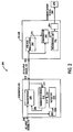
- FIG. 2 shows a block diagram of an embodiment of communicating a loss of an AC power supply.
- an apparatus 200 includes a broadband communication gateway 230 having one or more input ports such as input port 222 to receive a DC output signal 220 from one or more output ports such as output port 218 of an AC to DC converter 210 having a detector 216 to detect a loss of an AC input signal 212.
- the converter 210 further includes one or more inputs ports such as input port 208 to receive the AC input signal 212 from a conventional AC power supply.
- the converter 210 generates the direct current DC output signal 220 based on the AC input signal 212 and a feedback signal 206 generated by a feedback module 214 that is coupled to the detector 216.
- the converter 210 further includes isolation unit 224 such as an opto-isolator and transformer 226 to provide isolation between an AC portion and a DC portion of the converter 210.
- the isolation unit 224 to receive the AC input signal 212 and to generate a first voltage signal 228 that is sent to the detector 216 that generates a second voltage signal 229 in response to the first voltage signal 228.
- the second voltage signal 229 is sent to one or more input ports of the feedback module 214 such as input port 215.
- Input port 217 of the feedback module 214 receives the DC output signal 220 of the converter 210.
- the second voltage signal 229 offsets the DC output signal 220 by altering the feedback signal 206 based on the loss of the AC input signal 212 that is detected by the detector 216.
- the communication gateway 230 further includes a processing unit 250 coupled to or located within an analog front end 254 of the broadband communication gateway 230.
- the processing unit 250 generates a communication signal 260 based on the detection of the loss of the AC input signal 212.
- the processing unit 250 by controlling the analog front end 254 sends the communication signal or message 260 to a device external to the broadband communication gateway 230 in response to a interrupt signal 246 prior to the voltage of the DC output signal 220 decreasing below a threshold voltage needed for operation of the broadband communication gateway 230.
- the broadband communication gateway 230 further includes a comparator 240 to generate the interrupt signal 246 based on comparing the DC output signal 220 received from the converter 210 and a regulated voltage signal 244 provided by voltage regulators 242.
- the communication signal 260 is generated based on the processing unit 250 receiving the interrupt signal 246 that represents a predetermined change in the DC output signal 220.
- the predetermined change indicates that the loss of the AC input signal 212 has been detected by the detector 216.
- the predetermined change may include a five percent or greater change in the voltage level of the DC output signal 220.
- the predetermined change is a ten percent change in the voltage level of the DC output signal 220.
- the communication message 260 generated in response to the processing unit 250 receiving the interrupt signal 246 is based on the loss of the AC input signal 212 and indicates to at least one of a communications service provider and a communications maintenance provider a disconnect condition between the broadband communication gateway 230 and an external device 270 being monitored by at least one of the communications service provider and the communications maintenance provider.
- the external device 270 may be the DSLAM 102, a remote terminal, a central office, or other device for transferring communications between the broadband communication gateway 230 and the external device 270.
- At least one of the communications service provider and communications maintenance provider determine that the broadband communication gateway 230 is stopping a communication session because of the loss of the AC input signal in order for at least one of the communications service provider and communications maintenance provider to reassign bandwidth previously assigned to the broadband communication gateway.
- FIG 3 shows a block diagram of an embodiment of an AC to DC converter.
- the converter 300 converts an AC input signal 302 into a DC output signal 316 that provides power to a communication gateway as illustrated in Figure 4 .
- the AC input signal 302 may be any type of conventional AC signal such as a 120V or 240V AC signal.
- the AC input filter 304 removes transient noise from the AC input signal 302.
- a bridge rectifier 306 converts the AC input signal 302 into a DC signal.
- the bridge rectifier 306 provides full wave rectification from the two wire AC input signal 302. For both polarities of the voltage at the input bridge, the polarity of the output is constant with a pulsating magnitude.
- a filter capacitor 308 decreases the variations in the raw output voltage waveform from the bridge rectifier 306. An increase of voltage received by the filter capacitor 308 correspondingly stores excess charge in the capacitor 308 which may store up to approximately the peak voltage of the AC input signal 302. The charge in the filter capacitor 308 may temporarily discharge to provide a power source in the event of the loss of the AC input signal 302.
- the filter capacitor 308 charges to a high voltage greater than 120 volts that is approximately equal to a peak voltage of the AC input signal 302. For a typical 240V AC input signal 302 the peak voltage may be as high as 382V.
- the energy stored in a capacitor is proportional to the capacitance of the capacitor multiplied by the stored voltage of the capacitor squared.
- the filter capacitor 308, located in the converter 300 stores a certain energy value based on a low capacitance and the high peak voltage of the AC input signal 302 compared to a capacitor, located in the communication gateway 400, that receives a low voltage DC signal less than 24 volts such as 5 or 12 volts and requires a high capacitance to store the same certain energy value.
- a capacitor located in the communication gateway 400 having a high capacitance and a voltage less than 24 volts is substantially larger, more expensive, and less energy efficient compared to the filter capacitor 308 located in the converter having a low capacitance and a voltage greater than 120 volts.
- storing a certain amount of energy in the capacitor 308 having 382 volts and located in the converter 300 is approximately one thousand times more efficient than storing a like amount of energy in a 5 volt capacitor located in the communication gateway 400.
- a capacitor located in the converter 300, rather than the communication gateway 400 can have a significantly lower capacitance and consequently smaller size and cost. Storing the energy in the converter 300 for sustaining the communication gateway 400 long enough to generate the communication message 430 also shifts the size and cost burden to the converter 300, which has a smaller assembly and associated retooling costs compared to the communication gateway 400.
- the transformer 310 is an electrical device that transfers energy from an AC portion (left of the dotted line 340) to a DC portion (right of the dotted line 340) of the converter 300.
- a rectifier 312 rectifies the voltage signal received from the transformer 310 and a DC output filter 314 filters this voltage signal into the DC output signal 316 that provides power to the communication gateway 400.
- An opto-isolator 320 and detector 322 monitor the AC input signal 302.
- the opto-isolator 320 receives the AC input signal 302 and provides isolation between the AC and DC portions of the converter 300.
- the opto-isolator 320 includes a light emitting diode (LED) section 330 that receives the AC input signal 302 that may be a differential voltage scaled to protect the LED section 330 from overload.
- the opto-isolator 320 also includes a photo transistor section 332 that drives a missing pulse detector 322 that includes a retriggerable, resettable, monostable multivibrator. The detector 322 is powered by the DC output signal 316.
- the LED section 330 turns on and off at the AC frequency and the detector 322 is triggered at the same rate which may be 50 or 60 Hertz (Hz), for example.
- a 50 Hz frequency corresponds to a 20 millisecond time period of the AC input signal 302.
- the detector 322 includes a pulse generation component to set a pulse duration slightly longer than a period of the AC input signal 302.
- the pulse duration of the detector 322 is set to approximately ten percent longer than one cycle or period of the AC input signal 302. For example, an AC input signal 302 having a 20 millisecond time period would result in a pulse duration of 22 milliseconds for the detector. If a steady stream of the AC input signal 302 is present, the detector 322 is retriggered before an output pulse of the detector 322 times out and an output signal 323 of the detector 322 remains asserted without interruption.
- the detector 322 includes a CMOS integrated circuit with outputs that are driven symmetrically between ground and supply voltage. This output signal 323 can be applied via a filter (not shown) to the feedback voltage divider 324. When the detector 322 changes state the current added to the feedback voltage divider 324 offsets the DC output signal 316. A loss of the AC input signal 302 may be signaled as an approximately ten percent downward change in the DC output signal 316 in one embodiment. The magnitude of the remaining DC output signal 316 is such that the communication gateway 400 is still operational for certain functionality such as generating and sending a communication signal to a communications service provider or communication maintenance provider.
- the converter 300 further includes a feedback component that includes the feedback voltage divider 324, a shunt regulator 326, an opto-isolator 328, a switcher pulse width modulated controller 334, and a switch 336. These components collectively provide the feedback path for the DC output signal 316.
- the feedback voltage divider 324 includes various resistors that determine the voltage level of the DC output signal 316.
- the shunt regulator 326 provides an internal voltage reference while the opto-isolator 328 provides isolation between the AC and DC portions of the converter 300.
- the pulse width modulated controller 334 modulates a feedback signal 333 to generate a high frequency signal (e.g., sixty-four kilohertz) received by the transformer 310 in order to produce the DC output signal 316.
- a high frequency signal e.g., sixty-four kilohertz
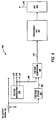
- FIG. 4 shows a block diagram of an embodiment of a communication gateway.
- the communication gateway 400 includes a voltage divider 402, voltage regulators 403, voltage comparator 404, processing unit 420 and analog front end (AFE) 424.
- the communication gateway 400 receives the DC output signal 316 from the converter 300.
- the voltage divider 402 scales the DC output signal 316 to a suitable level for the voltage comparator 404 that compares the DC signal 406 to a signal 408 of the voltage regulators 403.
- Inputs of the voltage regulators 403 are designed to absorb the decrease in the DC output signal 316 without producing harmful transients at outputs of the voltage regulators 403 based on the loss of the AC input signal 302.
- Voltage comparator 404 sends an interrupt signal 410 to the processing unit 420 that may be a system on a chip and/or an application specific integrated circuit (ASIC).
- the processing unit 420 may have a detector component (not shown) that determines whether a voltage level of the DC signal 410 has changed by a predetermined amount indicating the loss of the AC input signal 302.
- the processing unit 420 generates an interrupt service routine if the detector component determines that the voltage level of the interrupt signal 410 has changed by the predetermined amount.
- the predetermined change may include a five percent or greater decrease in the voltage level of the interrupt signal 410.
- the interrupt signal 410 starts a routine that generates the communication signal or message 430 that is sent to the communication service provider and/or maintenance provider by an analog front end circuit 424 being controlled by the processing unit 420.
- the communication message 430 indicates the loss of the AC power supply causing the disconnect of the communication gateway 400 from the central office or remote terminal of the telecommunication service provider.
- the interrupt signal 410 that starts the interrupt service routine may be non-maskable in that it has a higher priority than nearly all other operations of the processing unit 420.
- the communication message may be a dying gasp message that informs the terminal equipment at the central office that the subscriber is stopping a communication session such as DSL session because of an AC power failure. Using this information, the central office can free up and re-assign the terminal equipment. If the dying gasp signal were not sent, the terminal equipment would remain connected to the subscriber's inactive DSL line indefinitely, wasting the resource. A dying gasp signal can also log the AC power failure for customer service purposes.
- FIGS 3 and 4 illustrate an apparatus for providing DC power to a communication gateway for a short time after the loss of the AC input signal 302.
- the detector 322 is located in the converter 300, rather than the communication gateway 400, in order to quickly detect the loss of the AC input signal 302.
- the processing unit 420 can generate a disconnect message prior to the DC output signal decreasing to a voltage level below a threshold voltage necessary for operation of the communication gateway 400.
- the processing unit 420 may control an analog front end 424 that sends messages to the terminal equipment of the telephone company.
- Figures 3 and 4 may be altered in alternative embodiments of the present disclosure.
- a high frequency AC component e.g., 33kHz to 64kHz
- This AC component is generated in the converter 300 and shut off when the AC input signal is detected as missing using a similar detection technique as described above in reference to the detector 322.
- the high frequency AC component is detected in the communication gateway 400 with a tuned circuit, which has noise immunity advantages.
- the converter 300 further includes large inductor chokes in series with the DC path to add a high frequency AC component at the transmit end and separate this component from the DC component at the receiving end.
- the high frequency AC component may be a continuous wave or amplitude modulated with the AC input signal 302. If the high frequency AC component is amplitude modulated, then the burden of detecting the missing AC input signal 302 is shifted to the communication gateway 400.
- the detector component may be an easily obtained integrated circuit (IC) that requires a changing amplitude to set an automatic gain control for the IC.
- an impulse noise generated by the PWM controller 334 becomes a signaling medium using frequency shift keying.
- the switching frequency is detected in the communication gateway 400 as impulse noise.
- the frequency of the converter 300 is intentionally shifted.
- the frequency shift is detected in the communication gateway 400 and the interrupt signal generated by the processing unit 420.
- FIG. 5 shows a block diagram of an embodiment of a DC output waveform in response to the loss of an AC input signal.
- the AC input signal 502 may stop at any point in its cycle with the AC input signal 502 corresponding to the AC input signal 302 of Figure 3 in one embodiment.
- the DC output signal 504 has a nominal DC voltage 512, an AC missing DC voltage 514 and a zero DC voltage 516.
- the AC input signal 502 stops with a detection time period 506 following the time 520.
- a detector such as detector 322 detects the loss of the AC input signal 502.
- the detection time period 506 is approximately equal to or less than a period of the AC input signal 502 based on when the detector having a pulse duration slightly longer than the AC time period is retriggered by the AC input signal 502.
- the DC output signal 504 drops in voltage at the end of the detection time 506 based on the loss of the AC input signal 502.
- the DC output signal 504 may correspond to the DC output signal 316 in some embodiments of the present disclosure.
- a last communication time period 508 represents the time period needed for a communication gateway such as the communication gateway 400 to generate a last communication message that is sent to a communication service or maintenance provider in order to indicate a loss of connection based on the loss of the AC input signal 502.
- the last communication time period 508 is greater than or equal to 150 milliseconds.
- a capacitor or other energy storage device such as the filter capacitor 308 provides the energy to temporarily sustain a voltage of the DC output signal 504 greater than a threshold voltage required for operation of the communication gateway so that a processing unit such as the processing unit 420 can generate a communication message in the event of the loss of the AC input signal 502.
- the filter capacitor 308 may charge in the presence of the AC input signal 502 and discharge in the absence of the AC input signal 502.
- the filter capacitor 308 temporarily maintains the voltage of the DC output signal 504 greater than the threshold voltage required for operation of the communication gateway for a time period 508 greater than or equal to 150 milliseconds in order for the processing unit 420 to generate a communication message prior to the voltage of the DC output signal 504 decreasing below the threshold voltage and decaying during an arbitrary decay time period 510.
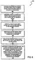
- Figure 6 shows a flow diagram for a method of communicating a loss of an AC power supply.
- the method includes receiving an AC input signal and a feedback signal from a feedback module located in a converter at block 602.
- the method further includes generating a DC output signal based on the AC input signal and the feedback signal at block 604.
- the method further includes detecting a loss of the AC input signal with a detector coupled to the feedback module at block 606.
- the loss of the AC input signal changes an amplitude of the DC output signal as illustrated in Figure 5 .
- the detector is located in the converter.
- the detector alters the feedback signal if the detector detects the loss of the AC input signal.
- the DC output signal is changed based on the detection of the loss of the AC input signal.
- the amplitude of the DC output signal changes based on the change in the feedback signal.
- the method further includes sending the DC output signal from the converter to a communication gateway at block 608.
- the method further includes receiving an interrupt signal based on the detection of the loss of the AC input signal at block 610.
- the method further includes generating a communication message in response to the interrupt signal prior to a voltage of the DC output signal decreasing below a threshold voltage needed for operation of the communication gateway at block 612.
- a converter provides power to a broadband communication gateway even if the AC power supply fails.
- a detector is located in the converter, rather than the broadband communication gateway, in order to quickly detect the loss of the AC power supply. Based on the quick detection, a processing unit located in the broadband communication gateway can generate a disconnect message prior to the DC output signal decreasing to a voltage level below a threshold voltage necessary for operation of the communication gateway.
Landscapes
- Engineering & Computer Science (AREA)
- Computer Networks & Wireless Communication (AREA)
- Signal Processing (AREA)
- Rectifiers (AREA)
- Data Exchanges In Wide-Area Networks (AREA)
- Telephonic Communication Services (AREA)
Claims (14)
- Appareil (100) comprenant: une passerelle de communication à large bande (CG, 106 ; 230 ; 400), ladite passerelle de communication à large bande incluant un ou plusieurs ports d'entrée (222) pour recevoir un signal de sortie (220; 316; 504) à courant continu, C.C., en provenance d'un convertisseur de courant alternatif, C.A. à C.C. (140 ; 210 ; 300) afin de détecter une perte d'un signal d'entrée C.A. (212 ; 302 ; 502) depuis une alimentation en énergie C.A. (130) se rendant au convertisseur ; et une unité de traitement (250 ; 420) destinée à générer un message de communication en réaction à la réception d'un signal d'interruption (246 ; 410) sur la base de la détection de la perte du signal d'entrée C.A. (212), l'unité de traitement pilotant un côté frontal analogique (254 ; 424) qui envoie le message de communication (260 ; 430) à un dispositif (270) externe par rapport à la passerelle de communication à large bande en réaction au signal d'interruption (246) avant qu'une tension du signal de sortie C.C. ne descende en dessous d'une tension-seuil qui est nécessaire pour le fonctionnement de la passerelle de communication à large bande, le message de communication (260 ; 430) lequel est généré en réaction au fait que l'unité de traitement (250) a reçu le signal d'interruption (246) indiquant à au moins l'un des suivants, soit un fournisseur de services de communications soit un fournisseur de maintenance de communications, un état de déconnexion entre la passerelle de communication à large bande (CG, 106 ; 230) et le dispositif externe (270) couplé à la passerelle de communication à large bande via un réseau téléphonique, caractérisé en ce que ladite passerelle de communication à large bande (CG, 106 ; 230) inclut un comparateur qui génère ledit signal d'interruption (246) sur la base de la comparaison entre le signal de sortie C.C. reçu en provenance du convertisseur et un signal de tension régulée (244) et lors de la détection d'un changement prédéterminé dans le signal de sortie C.C., le changement prédéterminé indiquant le changement dans ledit signal de sortie C.C. depuis une tension C.C. nominale (512) vers une tension C.C. de C.A. manquant (514).
- Appareil selon la revendication 1, le convertisseur comprenant en outre un ou plusieurs ports d'entrée pour recevoir un signal de rétroaction reçu en provenance d'un module de rétroaction couplé à un détecteur afin de détecter la perte du signal d'entrée C.A..
- Appareil selon la revendication 2, le changement prédéterminé comprenant un changement de dix pour cent approximativement dans le niveau de tension du signal C.C. reçu en provenance du comparateur.
- Appareil selon la revendication 2, le détecteur comprenant un multi-vibrateur monostable.
- Appareil selon la revendication 2, le détecteur comprenant un composant à génération d'impulsions dont la durée entre impulsions, lesquelles sont générées par le composant, est plus grande qu'une durée du signal d'entrée C.A..
- Appareil selon la revendication 2, le convertisseur comprenant en outre un photocoupleur pour procurer l'isolement entre une portion C.A. et une portion C.C. du convertisseur, le photocoupleur devant recevoir le signal d'entrée C.A. et générer un premier signal de tension qui est envoyé au détecteur, cas dans lequel le détecteur doit générer un deuxième signal de tension en réaction au premier signal de tension, le deuxième signal de tension étant envoyé à un ou plusieurs ports d'entrée du module de rétroaction.
- Appareil selon la revendication 6, lesdits un ou plusieurs ports du module de rétroaction devant recevoir le signal de sortie C.C. du convertisseur et le deuxième signal de tension en provenance du détecteur, le deuxième signal de tension devant décaler le signal de sortie C.C. dans le but de modifier le signal de sortie C.C. grâce à la modification du signal de rétroaction sur la base de la perte du signal d'entrée C.A..
- Appareil selon la revendication 1, au moins l'un des suivants, soit un fournisseur de services de communications soit un fournisseur de maintenance de communications, devant déterminer que la passerelle de communication à large bande arrête une session de communication en raison de la perte du signal d'entrée C.A. pour qu'au moins l'un des suivants, soit un fournisseur de services de communications soit un fournisseur de maintenance de communications, ré-attribue une bande passante précédemment attribuée à la passerelle de communication à large bande.
- Appareil selon la revendication 1, le convertisseur comprenant en outre : une portion C.A. avec une tension supérieure à 120 Volts possédant un condensateur de filtrage qui fournit un signal de sortie C.C. temporaire dans le but de maintenir temporairement une tension du signal de sortie C.C. à une valeur supérieure à la tension-seuil requise pour le fonctionnement de la passerelle de communication DSL de sorte que le côté frontal analogique puisse envoyer le message de communication dans l'éventualité de la perte du signal d'entrée C.A. ; et une portion C.C. avec une tension inférieure à 24 Volts.
- Appareil selon la revendication 9, le convertisseur comprenant en outre un photocoupleur pour procurer l'isolement entre la portion C.A. et la portion C.C. du convertisseur, le photocoupleur devant recevoir le signal d'entrée C.A. et générer un premier signal de tension qui est envoyé au détecteur.
- Appareil selon la revendication 10, le condensateur de filtrage devant conserver temporairement la tension du signal de sortie C.C. à une valeur plus élevée que la tension-seuil requise pour le fonctionnement de la passerelle de communication DSL pendant un intervalle de temps supérieur ou égal à la durée requise pour permettre à l'unité de traitement de générer le sous-programme de service d'interruption avant que la tension du signal de sortie C.C. ne descende en dessous de la tension-seuil.
- Appareil selon la revendication 9, le condensateur de filtrage devant charger jusqu'à une tension élevée supérieure à 120 Volts laquelle est approximativement égale à une tension de crête du signal d'entrée A.C., le condensateur de filtrage, localisé dans le convertisseur, devant stocker une certaine valeur énergétique sur la base d'une faible capacité et la tension élevée comparée à un condensateur, localisé dans la passerelle de communication DSL, qui reçoit un signal C.C. de faible tension inférieur à 24 Volts et nécessite une capacité élevée pour stocker la même certaine valeur énergétique.
- Appareil selon la revendication 1, le détecteur étant conçu pour détecter un changement dans une amplitude du signal d'entrée C.A..
- Procédé comprenant les opérations consistant à : recevoir un signal d'entrée (212 ; 302 ; 502) à courant alternatif (C.A.) et un signal de rétroaction (206 ; 333) en provenance d'un module de rétroaction (214) localisé dans un convertisseur (140 ; 210 ; 300) ; générer un signal de sortie (220 ; 316 ; 504) à courant continu (C.C.) sur la base du signal d'entrée C.A. et du signal de rétroaction ; et détecter une perte du signal d'entrée C.A. à l'aide d'un détecteur (216 ; 322) couplé au module de rétroaction, le détecteur étant localisé dans le convertisseur ; envoyer le signal de sortie C.C. en provenance du convertisseur vers une passerelle de communication à large bande (CG, 106 ; 230 ; 400) ; recevoir un signal d'interruption (246 ; 410) sur la base de la détection de la perte du signal d'entrée C.A. générant un message de communication (260 ; 430) qui est envoyé à un dispositif (270) externe par rapport à la passerelle de communication à large bande en réaction au signal d'interruption avant qu'une tension du signal de sortie C.C. ne descende en dessous d'une tension-seuil qui est nécessaire pour le fonctionnement de la passerelle de communication à large bande (CG, 106 ; 230 ; 400), caractérisé par le fait qu'un comparateur, faisant partie de la passerelle de communication à large bande (CG, 106 ; 230), génère ledit signal d'interruption (246) sur la base de la comparaison entre le signal de sortie C.C. reçu en provenance du convertisseur et un signal de tension régulée (244) et lors de la détection d'un changement prédéterminé dans le signal de sortie C.C., le changement prédéterminé indiquant le changement dans ledit signal de sortie C.C. depuis une tension C.C. nominale (512) vers une tension C.C. de C.A. manquant (514).
Applications Claiming Priority (2)
| Application Number | Priority Date | Filing Date | Title |
|---|---|---|---|
| US11/740,779 US7746877B2 (en) | 2007-04-26 | 2007-04-26 | Method and apparatus for communicating loss of alternating current power supply |
| PCT/US2008/002369 WO2008133768A1 (fr) | 2007-04-26 | 2008-02-21 | Procédé et appareil pour communiquer une perte d'alimentation en courant alternatif |
Publications (3)
| Publication Number | Publication Date |
|---|---|
| EP2140277A1 EP2140277A1 (fr) | 2010-01-06 |
| EP2140277A4 EP2140277A4 (fr) | 2011-09-21 |
| EP2140277B1 true EP2140277B1 (fr) | 2016-05-11 |
Family
ID=39886901
Family Applications (1)
| Application Number | Title | Priority Date | Filing Date |
|---|---|---|---|
| EP08725958.6A Active EP2140277B1 (fr) | 2007-04-26 | 2008-02-21 | Procédé et appareil pour communiquer une perte d'alimentation en courant alternatif |
Country Status (4)
| Country | Link |
|---|---|
| US (1) | US7746877B2 (fr) |
| EP (1) | EP2140277B1 (fr) |
| CA (1) | CA2685152C (fr) |
| WO (1) | WO2008133768A1 (fr) |
Families Citing this family (17)
| Publication number | Priority date | Publication date | Assignee | Title |
|---|---|---|---|---|
| US9106780B1 (en) * | 2009-02-23 | 2015-08-11 | Symantec Corporation | Method and apparatus for controlling audio/video display using a policy |
| US8477517B2 (en) * | 2009-04-21 | 2013-07-02 | Schweitzer Engineering Laboratories Inc | Contact-input arrangement for power system devices |
| FR2951837A1 (fr) * | 2009-10-28 | 2011-04-29 | Sagem Comm | Dispositif permettant l'emission sur un reseau d'un signal de baisse d'alimentation energetique, et procede associe |
| FR2979780A1 (fr) * | 2011-09-07 | 2013-03-08 | France Telecom | Passerelle domestique |
| US9093971B2 (en) * | 2012-03-30 | 2015-07-28 | Intel Corporation | Inverter-and-switched-capacitor-based squelch detector apparatus and method |
| US10039174B2 (en) | 2014-08-11 | 2018-07-31 | RAB Lighting Inc. | Systems and methods for acknowledging broadcast messages in a wireless lighting control network |
| US10085328B2 (en) | 2014-08-11 | 2018-09-25 | RAB Lighting Inc. | Wireless lighting control systems and methods |
| US10531545B2 (en) | 2014-08-11 | 2020-01-07 | RAB Lighting Inc. | Commissioning a configurable user control device for a lighting control system |
| US9883567B2 (en) | 2014-08-11 | 2018-01-30 | RAB Lighting Inc. | Device indication and commissioning for a lighting control system |
| US9779271B2 (en) | 2015-06-08 | 2017-10-03 | Juniper Networks, Inc. | Apparatus, system, and method for detecting theft of network devices |
| US11025090B2 (en) | 2016-03-02 | 2021-06-01 | International Business Machines Corporation | Determining location and disruption sequence of power outages |
| US12573965B2 (en) * | 2016-09-29 | 2026-03-10 | Transportation Ip Holdings, Llc | Harmonic distortion reduction system for converters connected to a common bus |
| CN106535224A (zh) * | 2016-10-14 | 2017-03-22 | 杭州鸿雁智能科技有限公司 | 一种移动式智能家居网关及其工作方法 |
| US10855104B2 (en) | 2018-03-14 | 2020-12-01 | Cisco Technology, Inc. | Dying gasp power apparatus |
| US10862298B2 (en) | 2018-04-11 | 2020-12-08 | Schweitzer Engineering Laboratories, Inc. | Duty cycle modulated universal binary input circuit with reinforced isolation |
| US11460902B2 (en) | 2019-11-08 | 2022-10-04 | Cisco Technology, Inc. | Energy recovery during system shutdown |
| US11934169B2 (en) | 2021-05-05 | 2024-03-19 | Schweitzer Engineering Laboratories, Inc. | Configurable binary circuits for protection relays in electric power systems |
Family Cites Families (23)
| Publication number | Priority date | Publication date | Assignee | Title |
|---|---|---|---|---|
| JPH03239159A (ja) * | 1990-02-15 | 1991-10-24 | Mitsubishi Electric Corp | 直流電源装置 |
| GB9500968D0 (en) | 1995-01-18 | 1995-03-08 | Magnum Power Solutions Ltd | Partitioned uninterruptible power supplies |
| US5946617A (en) * | 1996-06-28 | 1999-08-31 | Telxon Corporation | Cellular communication system with remote power source for providing power to access points |
| IL121230A (en) * | 1997-07-03 | 2004-05-12 | Nds Ltd | Intelligent electronic program guide |
| DE69918341T2 (de) * | 1998-03-04 | 2005-06-30 | United Video Properties, Inc., Tulsa | Programmführersystem mit Überwachung von Werbenutzung und Nutzeraktivitäten |
| US6295092B1 (en) * | 1998-07-30 | 2001-09-25 | Cbs Corporation | System for analyzing television programs |
| US6898762B2 (en) * | 1998-08-21 | 2005-05-24 | United Video Properties, Inc. | Client-server electronic program guide |
| TW463503B (en) * | 1998-08-26 | 2001-11-11 | United Video Properties Inc | Television chat system |
| TW499816B (en) * | 1998-11-30 | 2002-08-21 | United Video Properties Inc | Interactive program guide system and method |
| US6581163B1 (en) * | 1999-12-07 | 2003-06-17 | Cisco Technology, Inc. | Mains loss detection apparatus and method |
| EP1189422B1 (fr) * | 2000-08-29 | 2004-06-30 | Lucent Technologies Inc. | Système et procédé de service de téléphonie d'émergence pour abonnées d'une ligne numérique |
| US6975494B2 (en) * | 2001-01-29 | 2005-12-13 | Primarion, Inc. | Method and apparatus for providing wideband power regulation to a microelectronic device |
| KR100450963B1 (ko) * | 2001-08-16 | 2004-10-02 | 삼성전자주식회사 | 외장형 디지털 가입자 라인 통신단말의 다잉 개스프 처리방법 및 장치 |
| US20040073924A1 (en) * | 2002-09-30 | 2004-04-15 | Ramesh Pendakur | Broadcast scheduling and content selection based upon aggregated user profile information |
| US7003435B2 (en) * | 2002-10-03 | 2006-02-21 | Leviton Manufacturing Co., Inc. | Arc fault detector with circuit interrupter |
| US6897712B2 (en) * | 2003-08-18 | 2005-05-24 | International Business Machines Corporation | Apparatus and method for detecting loss of high-speed signal |
| DE102004002018A1 (de) * | 2004-01-14 | 2005-08-04 | Tridonicatco Gmbh & Co. Kg | DC-versorgte Betriebsmittel-Module für Leuchtmittel |
| KR100658854B1 (ko) * | 2004-08-20 | 2006-12-15 | 엘지전자 주식회사 | 영상표시기기의 채널 제어시스템 및 그 제어방법 |
| US7583202B2 (en) * | 2004-10-19 | 2009-09-01 | Echelon Corporation | Method and apparatus for an electric meter |
| US7321174B2 (en) * | 2005-01-06 | 2008-01-22 | International Business Machines Corporation | Apparatus, system, and method for maximizing power system holdup time during loss of input power |
| US20060274764A1 (en) * | 2005-06-02 | 2006-12-07 | Mah Donald T | Power saving methods in gateway |
| US20070058608A1 (en) * | 2005-09-09 | 2007-03-15 | Bellsouth Intellectual Property Corporation | Telephone network architecture for a voice over internet protocol service |
| US8613024B2 (en) * | 2005-12-13 | 2013-12-17 | United Video Properties, Inc. | Cross-platform predictive popularity ratings for use in interactive television applications |
-
2007
- 2007-04-26 US US11/740,779 patent/US7746877B2/en active Active
-
2008
- 2008-02-21 WO PCT/US2008/002369 patent/WO2008133768A1/fr not_active Ceased
- 2008-02-21 EP EP08725958.6A patent/EP2140277B1/fr active Active
- 2008-02-21 CA CA2685152A patent/CA2685152C/fr active Active
Also Published As
| Publication number | Publication date |
|---|---|
| WO2008133768A1 (fr) | 2008-11-06 |
| EP2140277A4 (fr) | 2011-09-21 |
| CA2685152C (fr) | 2013-07-02 |
| EP2140277A1 (fr) | 2010-01-06 |
| US7746877B2 (en) | 2010-06-29 |
| CA2685152A1 (fr) | 2008-11-06 |
| US20080267194A1 (en) | 2008-10-30 |
Similar Documents
| Publication | Publication Date | Title |
|---|---|---|
| CA2685152C (fr) | Procede et appareil pour communiquer une perte d'alimentation en courant alternatif | |
| EP3025489B1 (fr) | Système d'alimentation inverse pour noeud de télécommunications | |
| US6715087B1 (en) | Method of providing a remote power feed to a terminal in a local area network, and corresponding remote power feed unit, concentrator, repeator, and terminal | |
| US6917681B2 (en) | Peak power management and active decoupling arrangement for span-powered remote terminal access platforms | |
| US20030178979A1 (en) | Method and device for power supply in telecommunication systems | |
| US20020130641A1 (en) | Apparatus and method for providing span power to communication equipment at a customer premise | |
| CN1833262B (zh) | 线路供电网络部件中的输入电压感测电路 | |
| WO2007123650A1 (fr) | Procédé et appareil d'alimentation électrique d'interface réseau via les lignes téléphoniques | |
| US6320940B1 (en) | Network termination device with automatic detection and correction of circuit polarity | |
| US6047063A (en) | Methods and apparatus for providing an auxiliary communication line | |
| US8259929B2 (en) | Methods and apparatuses to provide a back up power supply for a network interface device | |
| JP4365408B2 (ja) | 回線電力供給型(linePowered)ネットワーク要素内の電流検知回路 | |
| AU2004307735B2 (en) | Method and apparatus for remote powering using multiple subscriber lines | |
| HK1059161A (en) | Method and device for power supply in telecommunication systems | |
| HK40035804A (en) | System and method for a subscriber-powered network element |
Legal Events
| Date | Code | Title | Description |
|---|---|---|---|
| PUAI | Public reference made under article 153(3) epc to a published international application that has entered the european phase |
Free format text: ORIGINAL CODE: 0009012 |
|
| 17P | Request for examination filed |
Effective date: 20091023 |
|
| AK | Designated contracting states |
Kind code of ref document: A1 Designated state(s): AT BE BG CH CY CZ DE DK EE ES FI FR GB GR HR HU IE IS IT LI LT LU LV MC MT NL NO PL PT RO SE SI SK TR |
|
| DAX | Request for extension of the european patent (deleted) | ||
| A4 | Supplementary search report drawn up and despatched |
Effective date: 20110822 |
|
| RIC1 | Information provided on ipc code assigned before grant |
Ipc: H04L 12/66 20060101ALI20110816BHEP Ipc: H04L 12/10 20060101ALI20110816BHEP Ipc: H02H 3/24 20060101ALI20110816BHEP Ipc: H04L 29/14 20060101ALI20110816BHEP Ipc: G01R 11/00 20060101AFI20110816BHEP Ipc: H02M 7/02 20060101ALI20110816BHEP Ipc: H04L 12/28 20060101ALI20110816BHEP |
|
| 17Q | First examination report despatched |
Effective date: 20150618 |
|
| GRAP | Despatch of communication of intention to grant a patent |
Free format text: ORIGINAL CODE: EPIDOSNIGR1 |
|
| RIC1 | Information provided on ipc code assigned before grant |
Ipc: H04L 29/14 20060101ALI20151221BHEP Ipc: G01R 11/00 20060101AFI20151221BHEP Ipc: H02H 3/24 20060101ALI20151221BHEP Ipc: H02M 1/00 20060101ALI20151221BHEP Ipc: H02M 7/02 20060101ALI20151221BHEP Ipc: H04L 12/66 20060101ALI20151221BHEP Ipc: H04L 12/10 20060101ALI20151221BHEP Ipc: H04L 12/28 20060101ALI20151221BHEP |
|
| INTG | Intention to grant announced |
Effective date: 20160120 |
|
| GRAS | Grant fee paid |
Free format text: ORIGINAL CODE: EPIDOSNIGR3 |
|
| GRAA | (expected) grant |
Free format text: ORIGINAL CODE: 0009210 |
|
| AK | Designated contracting states |
Kind code of ref document: B1 Designated state(s): AT BE BG CH CY CZ DE DK EE ES FI FR GB GR HR HU IE IS IT LI LT LU LV MC MT NL NO PL PT RO SE SI SK TR |
|
| REG | Reference to a national code |
Ref country code: GB Ref legal event code: FG4D |
|
| REG | Reference to a national code |
Ref country code: CH Ref legal event code: EP |
|
| REG | Reference to a national code |
Ref country code: AT Ref legal event code: REF Ref document number: 799059 Country of ref document: AT Kind code of ref document: T Effective date: 20160515 |
|
| REG | Reference to a national code |
Ref country code: IE Ref legal event code: FG4D |
|
| REG | Reference to a national code |
Ref country code: DE Ref legal event code: R096 Ref document number: 602008044183 Country of ref document: DE |
|
| REG | Reference to a national code |
Ref country code: LT Ref legal event code: MG4D |
|
| REG | Reference to a national code |
Ref country code: NL Ref legal event code: MP Effective date: 20160511 |
|
| PG25 | Lapsed in a contracting state [announced via postgrant information from national office to epo] |
Ref country code: NO Free format text: LAPSE BECAUSE OF FAILURE TO SUBMIT A TRANSLATION OF THE DESCRIPTION OR TO PAY THE FEE WITHIN THE PRESCRIBED TIME-LIMIT Effective date: 20160811 Ref country code: LT Free format text: LAPSE BECAUSE OF FAILURE TO SUBMIT A TRANSLATION OF THE DESCRIPTION OR TO PAY THE FEE WITHIN THE PRESCRIBED TIME-LIMIT Effective date: 20160511 Ref country code: NL Free format text: LAPSE BECAUSE OF FAILURE TO SUBMIT A TRANSLATION OF THE DESCRIPTION OR TO PAY THE FEE WITHIN THE PRESCRIBED TIME-LIMIT Effective date: 20160511 Ref country code: FI Free format text: LAPSE BECAUSE OF FAILURE TO SUBMIT A TRANSLATION OF THE DESCRIPTION OR TO PAY THE FEE WITHIN THE PRESCRIBED TIME-LIMIT Effective date: 20160511 |
|
| REG | Reference to a national code |
Ref country code: AT Ref legal event code: MK05 Ref document number: 799059 Country of ref document: AT Kind code of ref document: T Effective date: 20160511 |
|
| PG25 | Lapsed in a contracting state [announced via postgrant information from national office to epo] |
Ref country code: PT Free format text: LAPSE BECAUSE OF FAILURE TO SUBMIT A TRANSLATION OF THE DESCRIPTION OR TO PAY THE FEE WITHIN THE PRESCRIBED TIME-LIMIT Effective date: 20160912 Ref country code: ES Free format text: LAPSE BECAUSE OF FAILURE TO SUBMIT A TRANSLATION OF THE DESCRIPTION OR TO PAY THE FEE WITHIN THE PRESCRIBED TIME-LIMIT Effective date: 20160511 Ref country code: HR Free format text: LAPSE BECAUSE OF FAILURE TO SUBMIT A TRANSLATION OF THE DESCRIPTION OR TO PAY THE FEE WITHIN THE PRESCRIBED TIME-LIMIT Effective date: 20160511 Ref country code: LV Free format text: LAPSE BECAUSE OF FAILURE TO SUBMIT A TRANSLATION OF THE DESCRIPTION OR TO PAY THE FEE WITHIN THE PRESCRIBED TIME-LIMIT Effective date: 20160511 Ref country code: SE Free format text: LAPSE BECAUSE OF FAILURE TO SUBMIT A TRANSLATION OF THE DESCRIPTION OR TO PAY THE FEE WITHIN THE PRESCRIBED TIME-LIMIT Effective date: 20160511 Ref country code: GR Free format text: LAPSE BECAUSE OF FAILURE TO SUBMIT A TRANSLATION OF THE DESCRIPTION OR TO PAY THE FEE WITHIN THE PRESCRIBED TIME-LIMIT Effective date: 20160812 |
|
| PG25 | Lapsed in a contracting state [announced via postgrant information from national office to epo] |
Ref country code: IT Free format text: LAPSE BECAUSE OF FAILURE TO SUBMIT A TRANSLATION OF THE DESCRIPTION OR TO PAY THE FEE WITHIN THE PRESCRIBED TIME-LIMIT Effective date: 20160511 |
|
| PG25 | Lapsed in a contracting state [announced via postgrant information from national office to epo] |
Ref country code: DK Free format text: LAPSE BECAUSE OF FAILURE TO SUBMIT A TRANSLATION OF THE DESCRIPTION OR TO PAY THE FEE WITHIN THE PRESCRIBED TIME-LIMIT Effective date: 20160511 Ref country code: RO Free format text: LAPSE BECAUSE OF FAILURE TO SUBMIT A TRANSLATION OF THE DESCRIPTION OR TO PAY THE FEE WITHIN THE PRESCRIBED TIME-LIMIT Effective date: 20160511 Ref country code: EE Free format text: LAPSE BECAUSE OF FAILURE TO SUBMIT A TRANSLATION OF THE DESCRIPTION OR TO PAY THE FEE WITHIN THE PRESCRIBED TIME-LIMIT Effective date: 20160511 Ref country code: CZ Free format text: LAPSE BECAUSE OF FAILURE TO SUBMIT A TRANSLATION OF THE DESCRIPTION OR TO PAY THE FEE WITHIN THE PRESCRIBED TIME-LIMIT Effective date: 20160511 Ref country code: SK Free format text: LAPSE BECAUSE OF FAILURE TO SUBMIT A TRANSLATION OF THE DESCRIPTION OR TO PAY THE FEE WITHIN THE PRESCRIBED TIME-LIMIT Effective date: 20160511 |
|
| REG | Reference to a national code |
Ref country code: DE Ref legal event code: R097 Ref document number: 602008044183 Country of ref document: DE |
|
| REG | Reference to a national code |
Ref country code: FR Ref legal event code: PLFP Year of fee payment: 10 |
|
| PG25 | Lapsed in a contracting state [announced via postgrant information from national office to epo] |
Ref country code: AT Free format text: LAPSE BECAUSE OF FAILURE TO SUBMIT A TRANSLATION OF THE DESCRIPTION OR TO PAY THE FEE WITHIN THE PRESCRIBED TIME-LIMIT Effective date: 20160511 Ref country code: PL Free format text: LAPSE BECAUSE OF FAILURE TO SUBMIT A TRANSLATION OF THE DESCRIPTION OR TO PAY THE FEE WITHIN THE PRESCRIBED TIME-LIMIT Effective date: 20160511 Ref country code: BE Free format text: LAPSE BECAUSE OF FAILURE TO SUBMIT A TRANSLATION OF THE DESCRIPTION OR TO PAY THE FEE WITHIN THE PRESCRIBED TIME-LIMIT Effective date: 20160511 |
|
| PLBE | No opposition filed within time limit |
Free format text: ORIGINAL CODE: 0009261 |
|
| STAA | Information on the status of an ep patent application or granted ep patent |
Free format text: STATUS: NO OPPOSITION FILED WITHIN TIME LIMIT |
|
| 26N | No opposition filed |
Effective date: 20170214 |
|
| PG25 | Lapsed in a contracting state [announced via postgrant information from national office to epo] |
Ref country code: SI Free format text: LAPSE BECAUSE OF FAILURE TO SUBMIT A TRANSLATION OF THE DESCRIPTION OR TO PAY THE FEE WITHIN THE PRESCRIBED TIME-LIMIT Effective date: 20160511 |
|
| PG25 | Lapsed in a contracting state [announced via postgrant information from national office to epo] |
Ref country code: MC Free format text: LAPSE BECAUSE OF FAILURE TO SUBMIT A TRANSLATION OF THE DESCRIPTION OR TO PAY THE FEE WITHIN THE PRESCRIBED TIME-LIMIT Effective date: 20160511 |
|
| REG | Reference to a national code |
Ref country code: CH Ref legal event code: PL |
|
| PG25 | Lapsed in a contracting state [announced via postgrant information from national office to epo] |
Ref country code: CH Free format text: LAPSE BECAUSE OF NON-PAYMENT OF DUE FEES Effective date: 20170228 Ref country code: LI Free format text: LAPSE BECAUSE OF NON-PAYMENT OF DUE FEES Effective date: 20170228 |
|
| REG | Reference to a national code |
Ref country code: IE Ref legal event code: MM4A |
|
| PG25 | Lapsed in a contracting state [announced via postgrant information from national office to epo] |
Ref country code: LU Free format text: LAPSE BECAUSE OF NON-PAYMENT OF DUE FEES Effective date: 20170221 |
|
| REG | Reference to a national code |
Ref country code: FR Ref legal event code: PLFP Year of fee payment: 11 |
|
| PG25 | Lapsed in a contracting state [announced via postgrant information from national office to epo] |
Ref country code: IE Free format text: LAPSE BECAUSE OF NON-PAYMENT OF DUE FEES Effective date: 20170221 |
|
| PG25 | Lapsed in a contracting state [announced via postgrant information from national office to epo] |
Ref country code: MT Free format text: LAPSE BECAUSE OF NON-PAYMENT OF DUE FEES Effective date: 20170221 |
|
| PG25 | Lapsed in a contracting state [announced via postgrant information from national office to epo] |
Ref country code: HU Free format text: LAPSE BECAUSE OF FAILURE TO SUBMIT A TRANSLATION OF THE DESCRIPTION OR TO PAY THE FEE WITHIN THE PRESCRIBED TIME-LIMIT; INVALID AB INITIO Effective date: 20080221 |
|
| PG25 | Lapsed in a contracting state [announced via postgrant information from national office to epo] |
Ref country code: BG Free format text: LAPSE BECAUSE OF FAILURE TO SUBMIT A TRANSLATION OF THE DESCRIPTION OR TO PAY THE FEE WITHIN THE PRESCRIBED TIME-LIMIT Effective date: 20160511 |
|
| PG25 | Lapsed in a contracting state [announced via postgrant information from national office to epo] |
Ref country code: CY Free format text: LAPSE BECAUSE OF NON-PAYMENT OF DUE FEES Effective date: 20160511 |
|
| PG25 | Lapsed in a contracting state [announced via postgrant information from national office to epo] |
Ref country code: TR Free format text: LAPSE BECAUSE OF FAILURE TO SUBMIT A TRANSLATION OF THE DESCRIPTION OR TO PAY THE FEE WITHIN THE PRESCRIBED TIME-LIMIT Effective date: 20160511 |
|
| PG25 | Lapsed in a contracting state [announced via postgrant information from national office to epo] |
Ref country code: IS Free format text: LAPSE BECAUSE OF FAILURE TO SUBMIT A TRANSLATION OF THE DESCRIPTION OR TO PAY THE FEE WITHIN THE PRESCRIBED TIME-LIMIT Effective date: 20160911 |
|
| REG | Reference to a national code |
Ref country code: GB Ref legal event code: 732E Free format text: REGISTERED BETWEEN 20220414 AND 20220420 |
|
| REG | Reference to a national code |
Ref country code: DE Ref legal event code: R081 Ref document number: 602008044183 Country of ref document: DE Owner name: ARRIS SOLUTIONS, INC., SUWANEE, US Free format text: FORMER OWNER: 2WIRE, INC., SAN JOSE, CALIF., US Ref country code: DE Ref legal event code: R081 Ref document number: 602008044183 Country of ref document: DE Owner name: COMMSCOPE TECHNOLOGIES LLC, CLAREMONT, US Free format text: FORMER OWNER: 2WIRE, INC., SAN JOSE, CALIF., US Ref country code: DE Ref legal event code: R081 Ref document number: 602008044183 Country of ref document: DE Owner name: ARRIS SOLUTIONS LLC, SUWANEE, US Free format text: FORMER OWNER: 2WIRE, INC., SAN JOSE, CALIF., US |
|
| P01 | Opt-out of the competence of the unified patent court (upc) registered |
Effective date: 20230530 |
|
| REG | Reference to a national code |
Ref country code: DE Ref legal event code: R081 Ref document number: 602008044183 Country of ref document: DE Owner name: COMMSCOPE TECHNOLOGIES LLC, CLAREMONT, US Free format text: FORMER OWNER: ARRIS SOLUTIONS, INC., SUWANEE, GA, US Ref country code: DE Ref legal event code: R081 Ref document number: 602008044183 Country of ref document: DE Owner name: ARRIS SOLUTIONS LLC, SUWANEE, US Free format text: FORMER OWNER: ARRIS SOLUTIONS, INC., SUWANEE, GA, US |
|
| REG | Reference to a national code |
Ref country code: DE Ref legal event code: R081 Ref document number: 602008044183 Country of ref document: DE Owner name: COMMSCOPE TECHNOLOGIES LLC, CLAREMONT, US Free format text: FORMER OWNER: ARRIS SOLUTIONS LLC, SUWANEE, GA, US |
|
| REG | Reference to a national code |
Ref country code: GB Ref legal event code: 732E Free format text: REGISTERED BETWEEN 20240201 AND 20240207 |
|
| PGFP | Annual fee paid to national office [announced via postgrant information from national office to epo] |
Ref country code: DE Payment date: 20240228 Year of fee payment: 17 |
|
| PGFP | Annual fee paid to national office [announced via postgrant information from national office to epo] |
Ref country code: FR Payment date: 20250225 Year of fee payment: 18 |
|
| PGFP | Annual fee paid to national office [announced via postgrant information from national office to epo] |
Ref country code: GB Payment date: 20250227 Year of fee payment: 18 |
|
| REG | Reference to a national code |
Ref country code: DE Ref legal event code: R119 Ref document number: 602008044183 Country of ref document: DE |
|
| PG25 | Lapsed in a contracting state [announced via postgrant information from national office to epo] |
Ref country code: DE Free format text: LAPSE BECAUSE OF NON-PAYMENT OF DUE FEES Effective date: 20250902 |