EP2140403B1 - Dispositif et procédé pour déterminer un histogramme de côtés, dispositif et procédé de classement d'une image dans une base d'images de données, dispositif et procédé pour trouver deux images similaires et programme d'ordinateur - Google Patents
Dispositif et procédé pour déterminer un histogramme de côtés, dispositif et procédé de classement d'une image dans une base d'images de données, dispositif et procédé pour trouver deux images similaires et programme d'ordinateur Download PDFInfo
- Publication number
- EP2140403B1 EP2140403B1 EP08749049A EP08749049A EP2140403B1 EP 2140403 B1 EP2140403 B1 EP 2140403B1 EP 08749049 A EP08749049 A EP 08749049A EP 08749049 A EP08749049 A EP 08749049A EP 2140403 B1 EP2140403 B1 EP 2140403B1
- Authority
- EP
- European Patent Office
- Prior art keywords
- edge
- image
- gradient
- histogram
- information
- Prior art date
- Legal status (The legal status is an assumption and is not a legal conclusion. Google has not performed a legal analysis and makes no representation as to the accuracy of the status listed.)
- Active
Links
Images







Classifications
-
- G—PHYSICS
- G06—COMPUTING OR CALCULATING; COUNTING
- G06T—IMAGE DATA PROCESSING OR GENERATION, IN GENERAL
- G06T7/00—Image analysis
- G06T7/40—Analysis of texture
- G06T7/41—Analysis of texture based on statistical description of texture
- G06T7/44—Analysis of texture based on statistical description of texture using image operators, e.g. filters, edge density metrics or local histograms
-
- G—PHYSICS
- G06—COMPUTING OR CALCULATING; COUNTING
- G06F—ELECTRIC DIGITAL DATA PROCESSING
- G06F16/00—Information retrieval; Database structures therefor; File system structures therefor
- G06F16/50—Information retrieval; Database structures therefor; File system structures therefor of still image data
- G06F16/58—Retrieval characterised by using metadata, e.g. metadata not derived from the content or metadata generated manually
- G06F16/583—Retrieval characterised by using metadata, e.g. metadata not derived from the content or metadata generated manually using metadata automatically derived from the content
- G06F16/5854—Retrieval characterised by using metadata, e.g. metadata not derived from the content or metadata generated manually using metadata automatically derived from the content using shape and object relationship
-
- G—PHYSICS
- G06—COMPUTING OR CALCULATING; COUNTING
- G06V—IMAGE OR VIDEO RECOGNITION OR UNDERSTANDING
- G06V10/00—Arrangements for image or video recognition or understanding
- G06V10/40—Extraction of image or video features
- G06V10/50—Extraction of image or video features by performing operations within image blocks; by using histograms, e.g. histogram of oriented gradients [HoG]; by summing image-intensity values; Projection analysis
-
- G—PHYSICS
- G06—COMPUTING OR CALCULATING; COUNTING
- G06V—IMAGE OR VIDEO RECOGNITION OR UNDERSTANDING
- G06V10/00—Arrangements for image or video recognition or understanding
- G06V10/70—Arrangements for image or video recognition or understanding using pattern recognition or machine learning
- G06V10/74—Image or video pattern matching; Proximity measures in feature spaces
- G06V10/75—Organisation of the matching processes, e.g. simultaneous or sequential comparisons of image or video features; Coarse-fine approaches, e.g. multi-scale approaches; using context analysis; Selection of dictionaries
- G06V10/758—Involving statistics of pixels or of feature values, e.g. histogram matching
Definitions
- the present invention generally relates to an apparatus and method for determining an edge histogram of an image, to an apparatus and method for storing an image in an image database, to an apparatus and method for finding two similar images, and to a computer program.
- the present invention relates to a method of generating a texture edge histogram of digital images.
- the present invention relates to a content-based description of images based on color, texture and edge information, with the aim of being able to perform a similarity search or a classification of images into semantic groups.
- the Visual properties of the images are characterized for example by color features, texture features, edge features and / or shape features, so-called descriptors.
- descriptors For example, when archiving the images, these descriptors are automatically extracted and stored in a database.
- a distance measure defining the similarity of two images with respect to this descriptor is defined for each descriptor.
- a challenge or even a problem in the definition of a descriptor lies in optimally reproducing a "perceived" similarity (for example, by a human observer) of two images with respect to a visual feature over the distance measure.
- a content-based similarity search with respect to a descriptor takes place, for example, in the following way: a user or a user specifies a sample image.
- a search engine reads from this sample image the corresponding descriptor from a database and calculates the distance measures to all images in the database about the similarity measure of the descriptor. Images with a shortest distance (images with a sufficiently small distance, which is smaller than a predetermined threshold, for example) are outputted as a result of the search.
- an edge histogram descriptor (also referred to as an edge histogram descriptor) developed specifically for describing edge frequencies in images was good results for images in which clearly outlined objects stand out from a background.
- the said edge histogram descriptor which is described, for example, in US Pat US Pat. No. 6,807,298 B1 described, less good results when in pictures are areal texture, such. B. water surfaces or treetops. Such textures are also recognized as edges and mixed with clearly visible edges.
- descriptors that can be used specifically for textures.
- a so-called "homogeneous texture descriptor” (Homogeneous Texture Descriptor).
- the descriptors mentioned are generally based on an analysis of frequencies after a Fourier transformation, which is applied over the entire image, for example. Such descriptors are very well suited - this was also their purpose - when regular patterns such. B. carpet pattern or wallpaper pattern to be described. However, the descriptors mentioned are hardly suitable for photographs.
- Feature frequency matrices as texture image representation "by HC Shen and CYC Bie (published in” Pattern Recognition Letters 13 (1992), March, No. 3, Amsterdam, Niederlan de) describes a diagram for images with a homogeneous texture. Each image is represented as a set of feature frequency matrices that captures the occurrences of associated feature events. Feature events are extracted by operators defined by users and / or applications. The effectiveness of the presentation is shown by comparing it with other methods in classifying problems.
- the article "A Method for Classification of Scenery Documentary Using MPEG-7 Edge Histogram Descriptor" by J. Cao and A. Cai describes a dual threshold method of classifying a landscape documentary using an MPEG-7 edge histogram descriptor.
- the segments of a landscape documentary are classified into two categories, Building and Landscape Clips, through global EHD of recording keyframes using the Dual Threshold method.
- the basic semantics of each recording describing the building or the landscape can be extracted.
- the accuracy of the EHD calculation is increased by improving and smoothing the images, and the results of the classification are modified among the time constraints of recording key frames.
- a device for determining an edge histogram of an image according to claim 1 by an apparatus for storing an image in an image database according to claim 10, by a device for finding two similar images according to claim 11, by a method for determining an edge histogram of an image according to claim 12, by a method for storing an image in an image database according to claim 13, by a method for finding two similar images according to claim 14 and by a computer program according to claim 15.
- the present invention provides an apparatus for determining an edge histogram of an image based on information about a gradient strength and a gradient direction of a local gradient in an image content of a partial image of the image.
- the apparatus includes an allocator configured to associate the information about the gradient strength and the gradient direction based on an assignment rule to an edge type to obtain edge type information.
- the assignment rule is chosen such that, given a predetermined gradient direction, at least three different assigned edge types exist, which reflect different gradient strengths.
- the apparatus further includes an edge histogram determiner configured to determine the edge histogram based on the edge type information so that at least three edge types having different associated gradient strengths are distinguishable in the edge type histogram.
- Said embodiment of the present invention is based on the recognition that gradient strength is an essential feature in a description of an edge, and that a histogram describing various edge types in the image is particularly meaningful when in this histogram at least edge types with three different edge strengths are distinguishable.
- a histogram describing various edge types in the image is particularly meaningful when in this histogram at least edge types with three different edge strengths are distinguishable.
- the three different edge strengths that are differentiated in the generation of the edge type histogram reflect different surface types, namely, substantially monochromatic surfaces, textures, and object boundaries.
- the edge histogram is particularly meaningful and allows a distinction between images with many textures and images with many object boundaries.
- the described concept for generating an edge histogram enables a particularly reliable database search or a particularly reliable image comparison based on the edge histogram.
- the described concept for determining an edge histogram is equally applicable to a plurality of different images, substantially independent of the image motif, with good results.
- the present invention provides an apparatus for determining an edge histogram of an image based on information about local edge types for a plurality of adjacent image portions of the image.
- the apparatus comprises a weighting edge histogram determiner designed to provide weighted edge type frequency information representing an occurrence frequency of various local edge types describes to determine for an image section comprising a plurality of image parts to obtain the edge histogram.
- the weighting edge histogram determiner is designed to weight the occurrence of local edge types in image parts belonging to an extended edge extending over several image parts higher than the occurrence of local edge types when determining the weighted edge type frequency information. that belong to isolated local edges.
- the described aspect of the present invention is based on the recognition that edge types which belong to clearly visible (spatially) extended edges bear a particularly information value. It has been recognized that this circumstance, which is due to the fact that extended edges are perceived particularly clearly by a user, can be justified by a particularly strong weighting of the occurrence of the corresponding edge types. It should be noted that isolated local edges (ie, short edge portions that are not part of an extended long edge) typically occur in textures. Thus, typically, the isolated local edges (ie, edges having a length less than a predetermined threshold length) occupy a very large area of the image.
- Pronounced extended edges extending over several image parts ie, for example, edges whose length is greater than the edge length threshold value
- edges whose length is greater than the edge length threshold value take up only a small part of the image in terms of surface area. This is easy to understand because the extended edges usually form boundaries of objects, whereas the isolated local edges usually occur within the textures of the objects, thus filling surfaces of the objects. It is readily apparent that in many images, an area occupied by the surfaces is much larger than the area occupied by object boundaries. Thus, in an unweighted histogram, the occurrence of edge types would dominate isolated local edges. By a corresponding higher weighting of the occurrence of edge types with extended edges this imbalance is counteracted.
- edge histogram which adequately reflects the edge types of image portions associated with extended edges even in the presence of many isolated local edges.
- edge histogram is particularly well adapted to a human perception, and in turn allows a particularly well matched to the human perception of comparison of images.
- the present invention provides another means for determining an edge histogram of an image based on information about local edge types for a plurality of adjacent image portions of the image.
- the corresponding apparatus includes an edge histogram determiner configured to determine a histogram that summarizes edge type frequency information for a plurality of image parts belonging to a first block of image parts.
- the edge histogram determiner is further configured to determine an edge type associated with a maximum frequency value in the histogram as a block edge type for the first block.
- the edge histogram determiner is designed to determine respective respective histograms and corresponding respective block edge types for a plurality of further blocks.
- the edge histogram determiner is also adapted to determine a histogram describing a frequency of different edge types among the block edge types for the different blocks to obtain the edge histogram for the image.
- the above aspect is based on the knowledge that a block-by-block processing of the image leads to results which are particularly well adapted to the human visual impression and also result in low-interference results, if a more dominant one for each block Block edge type is identified for the determination of another, higher-level histogram. It was thus recognized that even a human observer assigns a dominant edge type to different areas of an image or document corresponding to the blocks of image parts. In forming the parent histogram describing the frequency of different edge types among the block edge types, non-dominant edge types of each block are thus disregarded.
- the described concept helps to obtain a particularly reliable edge histogram, which is particularly well suited for recognition. Since textures and object charges, as explained above, typically have different edge types, the described concept also makes it possible to clearly separate the named different edge types by determining a block edge type. Thus, for example, a block is assigned a specific edge type, which makes it possible to infer whether textures or object boundaries are dominant in the corresponding block. This effect also contributes to a further improvement in the quality of the edge histogram thus formed.
- the present invention further provides corresponding methods for determining an edge histogram of an image.
- the present invention provides apparatuses and methods for placing an image and finding two similar images. The devices and methods mentioned take advantage of the above findings and are based essentially on the concepts described above for determining an edge histogram.
- Fig. 1A - 1D 12 show a flowchart of a method for determining an edge histogram, according to an exemplary embodiment of the present invention.
- the procedure of Fig. 1A - 1D is designated in its entirety by 1000. It is assumed in the present description that the method 1000 receives as input a picture 1010, which for example is in digital form.
- the image 1010 may be given as a matrix of pixels, with the pixels arranged in the form of rows and columns.
- the image 1010 may alternatively be given in analog form, for example in the form of continuous electrical signals.
- horizontal direction along the lines of the image (that is, from a first column towards a last column).
- the vertical direction may, for example, run along the columns, for example from a first line to a last line.
- a representation of the image in the form of rows and columns is for example in the graph of Fig. 3 shown. That's how it shows Fig. 3 an image or digital image 200.
- a pixel is designated by way of example by 201.
- the pixels are labeled with two indices. For example, a first index 202 (first value in parenthesis), beginning with zero, describes a row number of a row in which the pixel is located.
- a second index 203 (second value in parenthesis) describes, starting at zero, a row number of a row in which the pixel is located.
- the aim of the method described by way of example below is to obtain a histogram which not only describes a local occurrence and a local frequency of edges in an image (for example in the image 1010), but also a local frequency or area of surfaces Textures describes.
- "Local” here means that the image (for example, the image 1010) is decomposed into rectangles, and that for each rectangle, the occurrence frequencies of certain textures and edges are determined and displayed in an overall histogram.
- the determination of this texture-edge histogram or overall histogram proceeds in several stages, as will be explained below.
- the method 1010 comprises, for example, first of all a determination of a local edge type 1020 for a picture part of the picture 1010.
- An image part will be understood below to mean, for example, a pixel.
- the image part may, however, also be a larger image detail, which may include a plurality of pixels.
- the method 1000 includes a first step 1032, in which a horizontal gradient with respect to intensity values for an image part (ie, for example, for a pixel) of the image is determined.
- a vertical gradient with respect to intensity values for the image part is further determined, for example.
- an image portion of the image is associated with a first gradient value (eg, a value of a horizontal gradient at the location of the image portion) and a second gradient value (eg, a value of a vertical gradient at the location of the image portion).
- first gradient value eg, a value of a horizontal gradient at the location of the image portion
- second gradient value eg, a value of a vertical gradient at the location of the image portion
- a Sobel operator or an optimized Sobel operator can be used, which can be applied to the intensity values of the pixels of the digital image.
- the horizontal gradient can be determined, for example, and by applying a second filter operator (which is different, for example, from the first filter operator, or can be rotated, for example, from the first filter operator)
- the vertical gradient can be calculated.
- the intensity values I (j, i) are the brightness values of the pixels, but also individual color channels or individual dimensions of color spaces. An example of a calculation of suitable intensity values I (j, i) will now be described.
- w (i) are weighting factors, 0 ⁇ i ⁇ Image.width indicating the pixel column in the image, 0 ⁇ j ⁇ image.Height indicating the pixel row in the image, h (j, i) the hue of the pixel in column i and Specifies row j in the HSV color space, s (j, i) indicates the chroma value of the pixel in column i and row j in the HSV color space, and v (j, i) indicates the brightness value of the pixel in column i and row j in the HSV color space indicates.
- the application of the Sobel operators on the first column and on the last column or on the first row and on the last row is not directly possible. Instead, here (ie in the first row and in the last row, as well as in the first column and in the last column) the corresponding values for the gradient are set to zero, for example.
- the horizontal gradient can be obtained as a locally variable function (in terms of rows and columns) by convolving the image 1010 with a horizontal Sobel operator and an optimized horizontal Sobel operator, respectively.
- a local gradient value can be calculated for each pixel position (with the exception of pixels along the image edges). For example, for the calculation of a local gradient value at a pixel position, pixels are included which are arranged in an environment of the relevant pixel position or which surround the relevant pixel position.
- a local gradient value for an image part or for a pixel position is understood to mean a gradient value which was determined using image parts surrounding the relevant image part or using pixel positions surrounding the pixel position.
- the vertical gradient can be obtained, for example, by folding the image 1010 with a vertical Sobel operator or an optimized vertical Sobel operator.
- a value of a horizontal gradient G x (j, i) and a value of a vertical gradient G y (j, i) are available for each pixel position (or associated with each image part).
- i and j respectively describe pixel positions, for example, where i denotes a pixel column, and j denotes, for example, a pixel row in the image.
- i and j may also generally refer to a position of image portions in the image.
- the method 1000 includes calculating a gradient strength 100 for the image part (or pixel) from the horizontal gradient and the vertical gradient. Furthermore, in a fourth step 1038, the method 1000 includes calculating a gradient direction or a gradient angle 101 for the image part or for the relevant pixel from the horizontal gradient and the vertical gradient. In other words, in steps 1036, 1038, a calculation becomes more general a gradient intensity 100 and a gradient angle 101 describing a gradient direction are made for each pixel in the image 1010 (or at least for a plurality of pixels) from the horizontal gradient G x and the vertical gradient G y . To illustrate the gradient direction or the gradient angle is applied to the Fig. 2A directed.
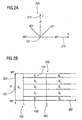
- the Fig. 2A shows a graphical representation of an orientation of the gradient angle.
- the graph according to the Fig. 2a is designated in its entirety by 200.
- Fig. 2a shows a coordinate system defined by an x-axis 210 as well as a y-axis 212.
- the x-axis 210 corresponds to a horizontal direction while the y-axis 212 corresponds to a vertical direction.
- a gradient angle of 0 ° corresponds to a vertical edge.
- a gradient angle of 45 ° for example, corresponds to a diagonally rising edge.
- a gradient angle of -45 ° corresponds to a diagonally descending edge.
- a gradient angle of 90 ° or -90 ° corresponds to a horizontal edge.
- the gradient direction is perpendicular to the course of the edge, since the gradient direction or the gradient angle describes the direction of a steepest change in intensity.
- an edge is substantially perpendicular to the direction of change of intensity.
- the gradient strength can be calculated by calculating the norm based on the horizontal gradient value and the vertical gradient value.
- the horizontal gradient value and the vertical gradient value are considered, for example, as components of a vector, where the gradient strength is then the magnitude or the length of the corresponding gradient vector.
- the gradient angle or the gradient direction which belongs to the pixel position (j, i) or to the image part with the indices (j, i) is designated here by ⁇ (j, i).
- Arctan refers to an arc tangent function.
- the gradient angle ⁇ (j, i) is in a range between -90 ° (not included) and 90 ° (included) (cf. Fig. 2b ).
- each pixel (or image part) at the location (j, i) of the image 1010 is assigned exactly one value for the gradient strength G (j, i) and exactly one value for the gradient angle ⁇ (j, i).
- the orientation of various gradient angles is, as previously described, in Fig. 2a shown.
- the image 1010 may be processed with at least three differently oriented filter operators.
- three or more filter values may be present for a specific pixel position or for a specific position of an image part (identified, for example, by indices (j, i)), wherein, for example, a first filter value is formed by the application of a horizontally oriented filter Filter value is formed by the application of a vertically oriented filter, and wherein, for example a third filter value is formed by the application of a filter oriented obliquely (for example at an angle of 45 °).
- these three filter values also include, for example, information about a gradient strength or a gradient direction. Namely, the direction is determined, for example, by which one of the three or more filter values is largest.
- the gradient strength is then defined, for example, by the largest of the filter values or by a combination of the filter values.
- information about a gradient strength and a gradient direction is understood to be any information, regardless of the specific form of the representation, from which the gradient strength and the gradient direction can be derived.
- the method 1000 includes determining a local edge type associated with the image part or the pixel, based on the gradient strength and the gradient direction. An assignment rule is used. Thus, information 1020 about a local edge type for an image part or for a pixel is produced.
- FIG. 12 is a graph describing a list of texture edge types by dividing the gradient strength gradient angle value range into subranges.
- FIG. 3 shows Fig. 3 a graphical representation of an assignment of pixels to texture edge types.
- gradient strength as well as gradient direction or gradient angle jointly determine whether a pixel (or image part) belongs to an edge, is part of a fine structure, or is also part of a structureless surface.
- a decomposition of the two-dimensional value range of the gradient strength and the gradient direction or of the gradient angle takes place.
- This type of decomposition leads to better search results (when using the method in connection with an identification or search of images). For example, using the decomposition described results in better search results than using an edge histogram, as shown in FIG US Pat. No. 6,807,298 B1 is described is possible.
- the range of values for the gradient G is in a range between zero and infinity. In a real embodiment, however, the range of values for the gradient strength is limited to the top. Further, it is assumed that the value range for the gradient angle is in a range between -90 ° (excluded) and + 90 ° (included).
- the gradient strength may assume non-negative real values.
- the gradient angle varies according to a definition used here from -90 ° (not included) to 90 °
- the Fig. 2B shows for this purpose a graphical representation of a number plane.
- the graphical representation is designated in its entirety by 250.
- the gradient strength is plotted.
- the gradient angle is plotted in a value range between -90 ° and + 90 °.
- the value range W is, for example, as in FIG. 2B represented, broken down into different sections. The decomposition takes place, for example, in disjoint sections, which however (taken together) cover the entire range of values.
- the decomposition is based on the following findings: it has been shown in studies that, in particular, highly visible edges in images, such as a silhouette or a skyline, or edges of buildings or objects, have a high gradient strength, while areas with fine textures , such as water surfaces, treetops or clouds are characterized by pixels with medium gradient strength. Smooth surfaces or surfaces with weak textures are characterized by pixels with low gradient strength.
- the range of values W with respect to the gradient G is broken down, for example, into three areas, which in the Fig. 2B are shown.
- two threshold values t u also denoted by 102
- t o also denoted by 103
- the two threshold values t u and t o are set, for example, so that the following visual classification can be made: 0 ⁇ G (j, i) ⁇ t u: Pixel belongs to a monotonous surface t u ⁇ G (j, i) ⁇ t o: without texture; Pixel belongs to a surface with texture; t o ⁇ G ( j, i ): Pixel is part of a well-visible edge.
- the value range W as in Fig. 2B represented, for example, in nine individual areas B 0 - B 8 is divided. If a gradient strength is smaller than the first threshold value t u , the edge type B 0 is assigned to a tuple (G, ⁇ ) independently of the gradient angle ⁇ .
- An area of average gradient strength (in which t u ⁇ G ⁇ t o ) and higher gradient strength (with t u ⁇ G) representing textures and edges is subdivided into further subregions with respect to the gradient angle ⁇ .
- An example of such a subdivision is the following:
- a first angle range (for example, between -22, 5 °, and + 22.5 °) is assigned an edge type that describes the presence of a vertical edge.
- a second angle region (for example,
- edge type area without texture and edges
- horizontal texture diagonal (descending) texture
- vertical texture diagonal (ascending) Texture
- horizontal edge a horizontal edge
- diagonal (descending) edge a vertical edge
- vertical edge diagonal (ascending) edge
- edge types may, for example, be identified by a numeric edge type identifier.
- the region B 0 ie the region with a low edge strength
- the areas B 1 -B 4 with medium edge strength represent textures with different texture directions.
- the areas B 5 - B 8 with (comparatively) high edge strength (greater than t o ) further represent edges with different edge directions.
- both surfaces without texture and edges, textures and edges are generally considered as "edges" or local edges to which a local edge type is correspondingly assigned.
- a texture is considered to be an edge of weaker edge strength (as compared to a true edge), and a surface without texture and edges is considered to be a very low edge strength edge (weaker than a texture).
- each pixel of the image has a gradient strength assigned to it and a gradient angle assigned to it exactly one subregion B k , for example 0 ⁇ k ⁇ 8, and thus a unique texture edge type (also referred to as edge type) Fig. 3 104 referenced) can be assigned.
- edges type also referred to as edge type
- pixels are represented by their texture edge type 104.
- the texture edge type 104 is also referred to as a local edge type 1020 for an image part or for a pixel.
- local edge types 1020 are determined for a plurality of image parts or for a plurality of pixels.
- histograms are formed over both the entire image and certain rectangular regions of the image indicating the frequency of the texture edge types of the pixels contained therein. From this an overall histogram can be formed.
- edges and textures are the result of a collection of adjacent pixels with specific properties. For example, a horizontal edge only becomes a clearly visible horizontal edge when in horizontal Adjacent pixels also have the edge property horizontal edge.
- the texture edge types in the image are detected in blocks as will be described below.
- weighted edge type frequency information 1046 for a frame is determined.
- An image section in this case comprises a plurality of image parts, that is, for example, a plurality of pixels.
- a corresponding image section is also sometimes referred to as a "block”.
- the sixth step 1042 includes determining a weighted edge type frequency information describing an occurrence frequency of different local edge types for a frame comprising a plurality of image parts. The occurrence of local edge types in image parts belonging to an extended edge extending over several image parts is weighted higher than the occurrence of local edge types of isolated local edges.
- edge type frequency information is determined which indicates for the various possible edge types (for example in the form of a histogram representation) how often the corresponding edge types occur in the image parts belonging to the image section.
- edge type frequency information indicates for the various possible edge types (for example in the form of a histogram representation) how often the corresponding edge types occur in the image parts belonging to the image section.
- not every occurrence of a certain edge type is necessarily simply counted. Rather, the occurrence of an edge type in an image part that belongs to an extended edge extending over several image parts is counted higher weighted (ie more than simple, for example, twice, weighted and counted).
- spatially extended edges that extend over a plurality of (for example, adjacent) image parts are weighted particularly heavily in the formation of the weighted edge frequency information.
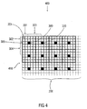
- Fig. 4 shows a graphical representation of a grid with blocks.
- the graphic representation of the Fig. 4 is designated in its entirety by 400.
- the graphical representation 400 shows a grid 410.
- the grid may define an array of pixels, where one pixel is labeled 201.
- a two-dimensional grid 410 consisting of grid points 300 is placed over the image. This is in the graph of Fig. 4 shown. From an initial pixel determined by an offset in both horizontal (301) and vertical (302) offset, for example, at fixed pitches in both the horizontal (303) and vertical (304), pixels are selected as grid points .
- a square block 305 of pixels is placed around each of these grid points (optionally) in such a way that a center of the block coincides with the grid point 300.
- the block has an odd one Page length in pixels.
- Fig. 4 shows the block formation.
- the offset 301, 302 in the grid 410 is selected, for example, so that a complete block can also be placed around the first row and around the first column of the grid points 300.
- the grid points of the last row and / or the last column should be defined in such a way that a complete block can be placed around them.
- the step sizes d x (also referred to as 303) and d y (also referred to as 304) should ideally be chosen to be as large as the page length of the blocks 305 to ensure complete coverage of the image with blocks and to minimize the number of blocks.
- the increments can also be chosen smaller, which leads to more blocks but also to a greater analysis effort.
- block.Width is the width of the block (for example, in the horizontal direction) and block.Height is the height of the block (for example, in the vertical direction) in pixels. (int) means "the integer value of the quotient".
- Each block is uniquely determined by the specification of the grid point by the two coordinates (j G , i G ).
- the blocks have been chosen so that the blocks cover the image gap-free in both the horizontal and vertical directions without overlapping each other.
- the block is uniquely identified by two indices j G and i G.
- the blocks of picture parts eg blocks of pixels
- the blocks into which the image 1010 is divided may be predefined.
- the blocks of pixels may be overlapping or non-overlapping. It is also possible that gaps between two adjacent blocks exist.
- the image has at least one block of image parts or a block of pixels, wherein the block of image parts or block of pixels comprises a plurality of pixels.
- a block of pixels define a plurality of adjacent pixels that form a contiguous pixel area.
- the processing is facilitated when a block of pixels defines a square or rectangular image detail. However, this is not absolutely necessary.
- a subsequent method step eg, the sixth step 1042 is to compute texture edge type frequencies for each block (or at least one block, or for a plurality of blocks).
- a (corresponding) texture edge type 104 is determined, for example (but not necessarily) using steps 1032 through 1040, and therefrom for the entire block the weighted frequencies 401 of - in the example described: 9 - calculates occurring texture edge types (cf. Fig. 5A ).
- the weighting of the texture edge types has the following background: Edges occupy little space compared to textures, but are perceived more intensively. This is the reason why pixels that are part of an edge and not part of a texture, that is, pixels that belong, for example, to the texture edge types B 5 through B 8 , in one embodiment, receive a higher weighting. Around For example, to ensure that the corresponding pixel is actually part of an edge, a higher weighting, for example, with a weighting factor of two (see reference numeral 400), is used (or only then) if the pixels adjacent in the edge direction are also of the same Texture edge type are. Fig. 5B represents this for four edge types.
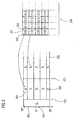
- Fig. 5A shows the weighting of the appearance of edge types graphically
- Fig. 5A a section of a representation that describes individual image parts (or pixels) associated edge types.
- a block 305 is shown that includes, for example, 5 x 5 pixels (indicated by the squares contained in block 5).
- Each of the pixels, one of which is designated 201, for example, is associated with a texture edge type 104 (from a range between B 0 and B 8 ) and a weighting factor or weight 400 (for example, a value of 1 or 2).
- An image portion or pixel is weighted higher in one embodiment of the present invention if the image portion or the pixel is part of an extended edge that spans multiple image portions or pixels.
- an extended edge has a length which is at least equal to a predetermined minimum length. For example, it may be defined that an extended edge exists only when a line-shaped edge extends over at least three pixels. It should also be noted that, for example, multiple pixels are classified as belonging to a common extended edge only if the mentioned (for example, at least three) pixels have the same edge type. Further, it can be checked in this regard whether the pixels having the same edge type are arranged in a direction adjacent to each other, which corresponds to the edge type of the pixels. This concept will be described below with reference to FIGS Fig. 5B explained. Fig. 5B shows for this purpose a schematic representation of three adjacent arranged Pixels.
- a first direction (for example, horizontal direction) is denoted by 510, and a second direction (for example, vertical direction) is denoted by 512.
- a first plot 520 shows three pixels 522, 524, 526 arranged side-by-side (eg adjacent, but possibly spaced apart) in a horizontal direction. All three pixels 522, 524, 526 have the edge type B 5 , which indicates a (local) horizontal edge. In other words, the pixel 522 is part of a local horizontal edge, as well as the pixel 524 and the pixel 526. Since the pixels 522, 524, 526 are arranged in the horizontal direction next to each other or in a line or along a line, the Pixel 522, 524, 526 also part of an extended horizontal edge.
- the weighting factor 2 is assigned to the middle of the pixels, that is to say the pixel 524 (see reference numeral 400).
- Another plot 530 shows three pixels 532, 534, 536 juxtaposed in the vertical direction and all having the edge type B 5 ("horizontal edge"). In this case, although three pixels with the same edge type lie in a line, the edge type (here: “horizontal edge”) does not correspond to the direction along which the pixels are arranged (here: vertical direction). As a result, the pixels 532, 534, 536 are given the weighting 1.
- a schematic representation 540 shows three pixels 542, 544, 546 having the edge type B 7 ("vertical edge") and juxtaposed in the vertical direction. Accordingly, the weighting factor 2 is assigned to the central pixel 544.
- the schematic representation 550 shows three pixels 552, 554, 556 juxtaposed in a diagonal ascending direction (upper right in the drawing). Since the three pixels 552, 554, 556 all have the edge type B 8 indicating a local diagonal (ascending) edge, the central pixel 552 becomes the weighting factor 2 assigned (see reference numeral 400).
- Another schematic representation 560 shows three pixels 562, 564, 566 juxtaposed in a diagonally descending direction (in the drawing, bottom right). Since all pixels 562, 564, 566 are assigned the edge type B 6 (diagonal descending edge), the weighting factor 2 is assigned to the central pixel 564.
- a corresponding weighting of the edge types is also shown in the graph of the Fig. 5A shown.
- This is how the graphic representation of the Fig. 5A for example, five pixels 504a, 504b, 504c, 504d, 504e, all of which are juxtaposed along a horizontal direction.
- two pixels 504a, 504c are located in a horizontal direction adjacent to the pixel 504b, with all of the named pixels 504a, 504b, 504c having the edge type "horizontal edge”. Therefore, the occurrence of the "horizontal edge” edge type in the pixel 504b is assigned a weighting factor of 2.
- the weighting factor 2 is also assigned to the occurrence of the "horizontal edge” edge type in the pixels 504c. The same applies to the weighting of the "horizontal edge” edge type in the pixel 504d.
- a pixel 506b is located between pixels 506a and 506c, with the pixels 506a, 506b, 506c arranged along a diagonally descending line, and with the pixels 506a, 506b, 506c being the same edge type "diagonal descending edge”. assigned.
- an edge type histogram reflects the weighted occurrence frequency of the individual edge types. If a weighting factor other than 1 is assigned to a pixel, the edge type at the relevant pixel becomes the weighting factor counted several times. For example, if pixel 504b has a weighting factor of 2, the edge type associated with pixel 504b provides a contribution of 2 to the histogram. In other words, the procedure is as if pixel 504b were duplicated.
- a histogram formed based on the block 305 is otherwise indicated at 508. An abscissa 509a describes how often the corresponding edge types occur in the block 305 (taking into account the weighting factors 400).
- column charts 509d-5091 indicate how often the corresponding edge types occur in block 305.
- the edge types B 2 , B 3 , B 4 , B 7 , B 8 occur only once in the block 305.
- the edge type B 1 occurs three times in the block 305.
- the edge type B 0 occurs four times in block 305.
- the edge type B 6 occurs only four times in the block 305, due to the double weighting of the pixel 506b, a weighted frequency value of 5 (3 ⁇ 1 plus 1 ⁇ 2) nevertheless results in the histogram 508 for the edge type B 6 .
- the mechanism for calculating the weighted edge frequency information and the weighted edge type histogram, respectively can be described as follows: a block of image parts (for example, pixels) is selected for which the edge type frequency information is then determined. Then, for several individual image parts, it is checked whether they are to be assigned a weighting higher than a standard weighting (the standard weighting being, for example, 1 or another predetermined standard weighting value). It is found that along a line that runs through the considered image part, in a given or given environment of the considered image part at least one predetermined If it is further determined that the direction of said line corresponds to the edge type, the image part considered is assigned a weighting factor higher than the standard weighting factor. Otherwise, the weighting factor is set to the standard weighting factor or left unchanged.
- a standard weighting being, for example, 1 or another predetermined standard weighting value
- edge type the considered image part has. Accordingly, it can then be decided, for example, along which direction neighboring image parts are to be checked with regard to their edge types. If it is determined, for example, that the edge of the image considered is assigned the "horizontal edge", then, for example, adjacent image parts are examined or checked, which are arranged in a horizontal direction next to the viewed image part. Image parts which are arranged in other directions next to the viewed image part are not considered in this case, for example. If the two parts of the image adjacent in the horizontal direction have the same edge types as the part of the image considered, that is, for example, also a horizontal edge type, then it is concluded that the considered image part is part of an extended edge. Accordingly, the weighting factor of the considered image part is increased. Otherwise, the weighting factor for the part of the image under consideration is left unchanged.
- edge types are always associated with a small weighting factor.
- edge types with low to medium edge strength can always be weighted with a standard weighting factor (for example, of 1), whereas higher edge weighting can only be used for edge types with a large edge strength.
- the decision includes a weighting factor of a considered part of the image also a decision as to whether a certain edge type can ever have a higher weighting factor than the basic weighting factor or standard weighting factor.
- each block for example, block (j G , i G )
- the corresponding grid point GP (j G , i G ) uniquely assigned a texture edge type.
- edge types which are associated with a greater edge strength or gradient strength, are preferred over edge types which have a lower edge strength or gradient strength.
- the connection types are B 5 to B 8, which is a great gradient associated, opposite the edge types B 1 to B 4, which is associated with an average gradient strength is preferred, and it also clarifies the edge types B 1 to B 4, which has an average Gradient strength is assigned before the edge type B 0 , which is associated with a low gradient strength, preferably.
- a predetermined preference order exists with respect to the edge directions. An edge type associated with a horizontal edge direction is preferred over an edge type associated with a vertical edge direction.
- edge type associated with a vertical edge direction is preferred over an edge type associated with a diagonally ascending edge direction
- an edge type associated with a diagonally ascending edge direction is preferred over an edge type associated with a diagonally descending edge direction
- edge types whose edge direction is parallel to the image edges of the image are preferred to edge directions whose edge direction is oblique to the image edges of the image.
- block block edge types are calculated for several blocks, moreover.
- the calculation can for example be made in the same way for all blocks.
- a group histogram is determined which is a frequency of different edge types among the block edge types for the blocks describes blocks belonging to the group.
- a plurality of blocks, for each of which a block edge type has been determined are logically combined into a group of blocks.
- a group histogram is then created for the group of blocks. In this case, only one block edge type assigned to the block is taken into account for each block. In other words, a histogram is created of how often the different edge types occur among the block edge types.
- the next method step relates to the generation of texture edge subhistograms (also referred to as a group histogram).
- the image is decomposed, for example, into image rectangles (designated by the reference numeral 500).
- the picture rectangles cover the picture as a whole.
- the image rectangles themselves may overlap themselves. Different variants are conceivable here: for example, 3 x 3 or 4 x 4 equal rectangles, or 2 x 2 equal rectangles and centered in the image another rectangle of equal size, whereby the middle area of the image is overweighted.
- the image is divided into 2 x 2 equal rectangles R 0 to R 3 .
- Fig. 8 Figure 11 is a graphic representation of an image divided into pixels, blocks and groups of blocks.
- Fig. 8 Fig. 12 is a graphical representation of an image divided into a plurality of different subunits.
- the picture according to the Fig. 8 is in its entirety denoted by 800.
- the image 800 includes a plurality of pixels 810 that form a grid of pixels.
- the pixels are preferably arranged in pixel lines, which run, for example, in a horizontal direction 812, and pixel columns, which run, for example, in a vertical direction 814.
- each pixel is typically associated with exactly one edge type. However, there may be pixels to which no edge type is associated, such as pixels along the edges of the image 800.
- a plurality of pixels form a block. Different blocks are labeled 820a to 820f.
- Each block 820a to 820f consists of a plurality of pixels.
- a block may consist of a rectangular or square array of individual pixels.
- each block is associated with information about weighted texture edge type frequencies (eg, a representation of a histogram having as many individual values as edge types are defined).
- each of the blocks 820a through 820f is assigned a representative texture edge type, also referred to as a block edge type.
- a plurality of groups of blocks are defined.
- a first group of blocks is labeled 830 and includes, for example, blocks 820a, 820b, 820e, and 820f.
- a second group of blocks includes blocks 820c, 820d, 820g, and 820h.
- the various groups of blocks are each rectangular and each comprise a plurality of blocks.
- a group of blocks is also referred to as "rectangle" in the present description.
- a so-called texture edge partial histogram can be created for each group of blocks.
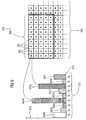
- the Fig. 6 shows in a graphical representation 610 a section of an image. Individual blocks, which are formed around selected grid points 300, for example, are designated 305. A group of blocks or an image rectangle is also denoted by 500 and comprises, for example, 9 ⁇ 6 blocks 305.
- the Fig. 6 also shows a graphical representation of a texture edge partial histogram 501.
- abscissa 620 for example, the individual edge types B 0 - B 8 are plotted, while an ordinate 622 describes a frequency of the various edge types B 0 - B 8 .
- Bars 624a to 624i describe the frequencies of the various block edge types among blocks 305 of the image rectangle 500.
- a texture edge subhistogram 501 is generated as follows: it the frequency of the texture edge type of blocks "block (j G , i G )" is determined whose grid point GP (j G , i G ) is contained in the rectangle.
- a texture edge sub-histogram of 9 values is generated which is normalized, for example, by dividing by the total number of grid points contained in the rectangle concerned.
- a ninth step 1054 comprises summarizing group histograms 1052 formed for several groups of blocks into a common histogram 1056.
- all texture edge subhistograms ie groups Histograms for multiple groups of blocks
- concatenation creates a texture edge histogram for the entire image.
- hist k * 9 + l thist k l With 0 ⁇ k ⁇ 4 and 0 ⁇ l ⁇ 9th
- Fig. 7 shows an image 200 that is decomposed into four rectangles 500. For each rectangle, there is an associated texture edge subhistogram 501. Thus, by merging the four respective texture edge subhistograms 501, a texture edge histogram 600 is produced for the entire image 200.
- steps d) and f) to i) are used to evaluate the results of steps c) and e).
- any method suitable for determining gradient strength and gradient direction information may occur.
- a particular advantage is achieved by mapping the information about the gradient strength and gradient direction in step 1040 to a local edge type 1020 for an image part such that at least three different gradient strengths can be distinguished on the basis of the local edge type.
- an edge type histogram is generated which includes a statement as to whether the image has a substantially monochromatic surface, a texture or a clearly visible edge respectively in which relationship the said structures appear in the image.
- steps 1042, 1048, 1050, 1054 may be replaced by any generation of a histogram based on the local edge type information 1020.
- the manner in which the information 1020 is generated via a local edge type may be substantially changed.
- the way in which the information about gradient strength and gradient direction is calculated, as well as on the way in which the local edge type is determined from the information about gradient strength and gradient direction does not matter in this embodiment.
- a particularly useful edge type histogram arises in the mentioned embodiment by the calculation of the weighted edge type frequency information 1046 in step 1042.
- the mentioned embodiment essentially benefits from the weighting.
- the weighted edge type frequency information obtained according to step 1042 may also be used in ways other than described above to generate an edge histogram.
- the steps 1048, 1050 and 1054 can also be replaced by one or more other steps.
- the weighted edge type frequency information 1046 may also be used directly as the edge type histogram.
- an edge type histogram is achieved by calculating a block edge type for a block of image parts in accordance with step 1048, and further based on a histogram on the block edge types for multiple blocks.
- the above procedure results in a higher-level histogram over the block edge types of multiple blocks, with only one "dominant" edge type being used for each block.
- the enhancement of the edge histogram is achieved by omitting information that is not dominant, for example, the information about the other edge types that were not selected as the block edge type. Therefore, in the aforementioned embodiment, it does not matter how the edge type frequency information is calculated for the blocks of image parts.
- the block edge type designation 1048 uses weighted edge type frequency information for the blocks or unweighted edge type frequency information for the blocks.
- steps 1032, 1034, 1036, 1038, 1040, 1042 may be arbitrarily changed or omitted as long as it is ensured that a block edge type is selected based on an edge type information for a block of image parts.
- based on the block edge types for a plurality of blocks forms another histogram, as described for example by step 1050. However, it is not essential how the corresponding group histogram 1052 is processed.
- weighted edge type frequency information it is important to generate weighted edge type frequency information based on information about local edge types.
- it does not matter how the information about local edge types is obtained.
- it does not matter how exactly an edge type histogram is obtained from the weighted edge type frequency information.
- a histogram is formed over block edge types.
- how the edge type frequency information required for determining the block edge types is obtained is irrelevant to the basic mode of operation of the third exemplary embodiment. Likewise, it does not matter if and how the group histogram is further processed.
- edge histograms calculated according to the invention can be further processed.
- the examples described below are not exhaustive representations of possible applications, but are to be considered as exemplary only.
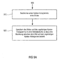
- Fig. 9A a flowchart of a method for placing an image in an image database.
- the method according to the Fig. 9A in its entirety designated 900.
- the method 900 comprises, in a first step 910, determining an edge histogram of an image, as explained in detail in the context of the present description.
- the method further includes, in a second step 920, storing the image and the associated edge histogram in an image database such that there is a relationship between the image and the associated edge histogram.
- the edge histogram in compressed or uncompressed form
- the edge histogram may be stored together in a common file with the image.
- an image database is created that includes, in addition to the image, the edge histogram associated with the image. This makes it possible to identify an image using the image database particularly reliable. This is because the edge histogram generated according to the invention is particularly reliable due to the type of generation described above.
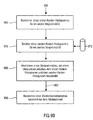
- FIG. 10 shows a flow chart of a method for finding two similar images, according to one embodiment of the present invention.
- the method according to the Fig. 9B is designated in its entirety with 950.
- the method 950 may be used to determine similarity information with respect to two given images.
- the method 950 may be used to calculate based on a given example image to identify an image in an image database.
- the method 950 includes, in a first step 960, determining a first edge histogram for a first comparison image. The determination of the first edge histogram may, for example, be carried out in the manner described above.
- the method 950 includes, in a second step 970, obtaining a second edge histogram for a second comparison image.
- the second edge histogram for the second comparison image may be obtained, for example, according to the method described above.
- the second edge histogram can, for example, also be read out of a database 972 into which it has previously been stored, for example.
- storing the second edge histogram in the database is not necessarily part of the method 950.
- the method 950 further includes, in a third step 980, determining a distance measure describing a difference between the first edge histogram and the second edge histogram.
- a distance measure 982 can be obtained.
- the distance measure 982 is thus a measure of a difference between two images. For example, if there are corresponding texture edge histograms for the first comparison image and the second comparison image (for example, a first texture edge histogram for the entire first image and a second texture edge histogram for the entire second image, as described by hist is defined), so in a distance computation of two images with respect to the texture edge histogram, the two histograms can be treated as vectors.
- a distance measure for example, apply the usual distance vectors valid for vectors, such. B.
- an edge histogram for the first image may be construed as a first vector
- an edge histogram for the second image may be construed as a second vector.
- a distance measure that the Difference between the two images can be calculated by determining a distance between said vectors. Different distance measures describing distances between two vectors are known from the field of mathematics. Further, based on the distance measure 982, in a (optional) fourth step 990, similarity information indicative of similarity between the first comparison image and the second comparison image may be determined.
- the distance measure and / or the similarity information it may be decided (for example, using a threshold value) whether the first comparison image and the second comparison image are sufficiently similar. Based on this information, it can also be decided, for example, whether the second comparison image stored, for example, in a database should be output to a user.
- the method can be carried out as a whole or in individual sub-steps.
- the individual partial steps of the method can also be carried out at different locations (for example on different computers networked with one another).
- the methods described above can also be realized by corresponding devices.
- the methods described above can be realized by a corresponding circuit arrangement.
- a logic circuit for example, a field programmable gate array, also known as FPGA
- the methods according to the invention can thus also be represented by corresponding programming data for an FPGA.
- the method according to the invention can be realized, for example, by a computer comprising instructions which enable the execution of the define the method described.
- the methods described above may also be implemented in software.
- the devices and methods of the invention may be implemented in hardware or in software.
- the implementation may be on a digital storage medium, such as a floppy disk, a CD, a DVD, a ROM, a PROM, an EPROM, an EEPROM, or a FLASH memory, with electronically readable control signals that may interact with a programmable computer system in that the corresponding method is carried out.
- the present invention thus also consists in a computer program product with program code stored on a machine-readable carrier for carrying out the method according to the invention, when the computer program product runs on a computer.
- the invention can be realized as a computer program with a program code for carrying out the method according to the invention, when the computer program runs on a computer.
- embodiments of the present invention result in significantly better search results in a similarity-based image search. This improvement is due to the fact that the frequency of the individual image areas occurring edges and textures is considered together. In contrast, previous systems often consider edges and textures separately.
- overlays that conventionally degrade search results on, for example, images containing surfaces with textures are avoided.
- An embodiment of the invention provides an apparatus for determining an edge histogram 1046; 1052; 1056 an image 1010 based on information about a gradient strength and a gradient direction of a local gradient in an image content of a partial image of the image, comprising: an allocator configured to supply the information about the gradient strength and the gradient direction based on an assignment rule assign an edge type to obtain an edge type information 1020, wherein the assignment rule is selected such that at a predetermined gradient direction there exist at least three different associated edge types reflecting different gradient strengths; and an edge histogram determiner configured to determine the edge histogram based on the edge type information such that at least three edge types having different associated gradient strengths are distinguishable in the edge type histogram, the assigner being configured to: a directional resolution of the assignment with respect to the gradient direction is dependent on the gradient strength.
- An embodiment of the invention provides an apparatus as mentioned above, further comprising a gradient determiner configured to filter the image using a first filter operator to obtain a first gradient information with respect to a first direction in the image that is designed to filter the image using a second filter operator to obtain gradient information with respect to a second direction in the image, and further configured to display the information about the gradient strength and the gradient direction based on the first gradient information and the second To obtain gradient information.
- a gradient determiner configured to filter the image using a first filter operator to obtain a first gradient information with respect to a first direction in the image that is designed to filter the image using a second filter operator to obtain gradient information with respect to a second direction in the image, and further configured to display the information about the gradient strength and the gradient direction based on the first gradient information and the second To obtain gradient information.
- An embodiment of the invention provides an apparatus as mentioned above, wherein the gradient determiner is arranged to derive the information about the gradient strength from the first gradient information and the second gradient information using a local norm operator.
- An embodiment of the invention provides an apparatus as mentioned above, wherein the gradient determiner is configured to obtain the first gradient information and the second gradient information such that the first direction is substantially orthogonal to the second direction, and wherein the gradient determiner is further configured to derive the information about the gradient direction using a trigonometric function from the first gradient information and the second gradient information.
- An embodiment of the invention provides an apparatus as mentioned above, wherein the allocator is adapted to process the gradient direction in the form of a gradient angle.
- An embodiment of the invention provides an apparatus as mentioned above, the apparatus being arranged to obtain information on gradient strengths and gradient directions for a plurality of adjacent image portions of the image and to obtain associated information about local edge types for a plurality of adjacent image portions of the image
- the edge histogram determiner is adapted to determine a histogram which summarizes edge type frequency information for a plurality of image parts belonging to a first block of image parts, and an edge type in the histogram maximum frequency value is assigned to determine as a block edge type for the first block; wherein the edge histogram determiner is further configured to determine a respective histogram and a respective block edge type for a plurality of further blocks; and wherein the edge histogram determiner is further adapted to determine a histogram describing a frequency of different edge types among the block edge types for the different blocks to obtain the edge histogram for the image.
- An embodiment of the invention provides an apparatus as mentioned above wherein the edge histogram determiner is arranged to combine a first plurality of blocks into a first group of blocks and a second plurality of blocks extending from the first plurality of blocks at least in one block differs to group into a second group of blocks; wherein the edge histogram determiner is adapted to obtain a first group histogram describing a frequency of different edge types among the block edge types for the blocks of the first group of blocks, and a second group histogram to obtain a frequency of different edge types among the block edge types for the blocks of the second group of blocks; and wherein the edge histogram determiner is arranged to combine the first group histogram and the second group histogram into an overall histogram.
- An embodiment of the invention provides an apparatus as mentioned above, wherein the edge histogram determiner is arranged to divide the image into a plurality of groups of blocks, each block comprising a plurality of image portions to correspond to each of the groups of blocks To obtain group histogram; and wherein the edge histogram determiner is arranged to summarize the group histograms by juxtaposing the group histograms into a total histogram.
- An embodiment of the invention provides an apparatus as mentioned above, wherein the edge histogram determiner is arranged to select, in addition to the groups of blocks into which the image is divided, another group of blocks comprising an image center to influence the center of the image to the overall histogram.
- An embodiment of the invention provides an apparatus as mentioned above, wherein a group of blocks defines a rectangular image area.
- An embodiment of the invention provides an apparatus as mentioned above, wherein all groups of blocks define image areas of equal size.
- An embodiment of the invention provides an apparatus as mentioned above, wherein the edge histogram determiner is adapted to take into account, in a predetermined order, edge types to which equal frequency values and different directions are assigned in determining the block edge type.
Landscapes
- Engineering & Computer Science (AREA)
- Theoretical Computer Science (AREA)
- Physics & Mathematics (AREA)
- General Physics & Mathematics (AREA)
- Computer Vision & Pattern Recognition (AREA)
- Databases & Information Systems (AREA)
- Multimedia (AREA)
- Library & Information Science (AREA)
- Computing Systems (AREA)
- Artificial Intelligence (AREA)
- Probability & Statistics with Applications (AREA)
- Evolutionary Computation (AREA)
- General Health & Medical Sciences (AREA)
- Medical Informatics (AREA)
- Software Systems (AREA)
- Health & Medical Sciences (AREA)
- Data Mining & Analysis (AREA)
- General Engineering & Computer Science (AREA)
- Image Analysis (AREA)
- Image Processing (AREA)
- Studio Devices (AREA)
Claims (15)
- Dispositif pour déterminer un histogramme de côtés (1046; 1052; 1056) d'une image (1010) sur base d'une information sur une intensité et une direction d'un gradient local dans un contenu d'une image partielle de l'image, aux caractéristiques suivantes:un associateur qui est conçu pour associer l'information sur l'intensité de gradient et la direction de gradient à un type de côté sur base d'une règle d'association, pour obtenir une information de type de côté (1020),la règle d'association étant choisie de sorte qu'à une direction de gradient prédéterminée existent au moins trois types de côté différents qui reflètent différentes intensités de gradient; etun déterminateur d'histogramme de côtés qui est conçu pour déterminer l'histogramme de côtés sur base de l'information de type de côté, de sorte que dans l'histogramme de types de côté puissent être distingués au moins trois types de côté à différentes intensités de gradient associées,l'associateur étant conçu de sorte qu'une résolution de direction de l'association par rapport à la direction de gradient soit fonction de l'intensité de gradient.
- Dispositif selon la revendication 1, dans lequel l'associateur est conçu pour distinguer au moins trois intervalles d'intensités de gradient lors de l'association à des types de côté.
- Dispositif selon l'une des revendications 1 et 2, dans lequel l'associateur est conçu pour associer l'information sur l'intensité de gradient et la direction de gradient indépendamment de l'angle à un premier type de côté (B0) lorsque l'intensité de gradient n'excède pas une première valeur de seuil d'intensité de gradient prédéterminée (tu), et pour associer l'information sur l'intensité de gradient et la direction de gradient en fonction de l'angle à différents types de côté (B5, B6, B7, B8) lorsque l'intensité de gradient excède une deuxième valeur de seuil d'intensité de gradient prédéterminée (to).
- Dispositif selon l'une des revendications précédentes, dans lequel l'associateur est conçu de sorte que la résolution de direction de l'association par rapport à la direction de gradient augmente, à intensité de gradient croissante, en au moins deux étapes, de sorte que la résolution de direction adopte, en fonction de l'intensité de gradient, au moins trois étages différentes.
- Dispositif selon l'une des revendications 1 à 4, dans lequel l'associateur est conçu pour associer, en cas de faible intensité de gradient inférieure à une première valeur de seuil d'intensité de gradient (tu), l'information sur l'intensité de gradient et la direction de gradient indépendamment de l'angle à un premier type de côté (B0),
pour associer, en cas de moyenne intensité de gradient supérieure à la première valeur de seuil d'intensité de gradient (tu) et inférieure à une deuxième valeur de seuil d'intensité de gradient (to), l'information sur l'intensité de gradient et la direction de gradient en fonction de la direction de gradient à un type de côté parmi un premier ensemble de quatre types de côté (B1, B2, B3, B4), et
pour associer, en cas de haute intensité de gradient supérieure à la deuxième valeur de seuil d'intensité de gradient (to), l'information sur l'intensité de gradient et la direction de gradient en fonction de la direction de gradient à un type de côté parmi un deuxième ensemble de types de côté (B5, B6, B7, B8). - Dispositif selon la revendication 5, dans lequel l'associateur est conçu pour distinguer en tout neuf types de côté, le deuxième ensemble de types de côté comprenant quatre types de côté différents.
- Dispositif selon l'une des revendications 1 à 6, dans lequel le déterminateur d'histogramme de côtés comporte un déterminateur d'histogramme de côtés de pondération conçu pour déterminer une information de fréquence de type de côté pondérée décrivant une fréquence d'occurrence de différents types de côté locaux pour une découpe d'image comportant une pluralité de parties d'image, pour obtenir l'histogramme de côtés;
le déterminateur d'histogramme de côtés de pondération étant conçu pour, lors de la détermination de l'information de fréquence de type de côté pondérée, pondérer l'occurrence de types de côté locaux dans des parties d'image appartenant à un côté étendu s'étendant sur plusieurs parties d'image de manière plus élevée que l'occurrence de types de côté locaux appartenant à des côtés locaux isolés. - Dispositif selon l'une des revendications 1 à 7, dans lequel le dispositif est conçu pour obtenir une information sur les intensités de gradient et les directions de gradient pour une pluralité de parties adjacentes de l'image et une information associée sur les types de côté locaux pour une pluralité de parties adjacentes de l'image,
le déterminateur d'histogramme de côtés étant conçu pour déterminer, comme type de côté de bloc pour le premier bloc, un histogramme regroupant une information de fréquence de type de côté pour plusieurs parties d'image appartenant à un premier bloc de parties d'image, et pour déterminer un type de côté auquel est associée, dans l'histogramme, une valeur de fréquence maximale;
le déterminateur d'histogramme de côtés étant par ailleurs conçu pour déterminer un histogramme respectif et un type de côté de bloc respectif pour une pluralité d'autres blocs; et
le déterminateur d'histogramme de côtés étant par ailleurs conçu pour déterminer un histogramme décrivant une fréquence de différents types de côté parmi les types de côté de bloc pour les différents blocs, pour obtenir l'histogramme de côtés pour l'image. - Dispositif selon la revendication 8, dans lequel le déterminateur d'histogramme de côtés est conçu pour, lors de la détermination du type de côté de bloc, préférer un type de côté auquel est associée une intensité de côté comparativement grande à un type de côté auquel est associée une intensité de côté comparativement petite lorsqu'il est associé pour les types de côté une même valeur de fréquence.
- Dispositif pour classer une image dans une banque de données d'image, aux caractéristiques suivantes:un dispositif pour déterminer un histogramme de côtés de l'image, selon l'une des revendications 1 à 9; etun moyen pour mémoriser l'image et l'histogramme de côtés y relatif dans la banque de données d'image, de sorte qu'il existe un rapport entre l'image et l'histogramme de côtés y relatif.
- Dispositif pour trouver deux images similaires, aux caractéristiques suivantes:un déterminateur d'histogramme de côtés conçu pour déterminer un premier histogramme de côtés pour une première image de comparaison, selon l'une des revendications 1 à 9;un dispositif pour obtenir un deuxième histogramme de côtés d'une deuxième image de comparaison;un déterminateur d'informations de similitude conçu pour obtenir une information de similitude décrivant une similitude entre un contenu d'image de la première image de comparaison et un contenu d'image de la deuxième image de comparaison,le déterminateur d'informations de similitude étant conçu pour obtenir l'information de similitude sur base d'une mesure de distance,la mesure de distance décrivant une différence entre le premier histogramme de côtés et le deuxième histogramme de côtés.
- Procédé pour déterminer un histogramme de côtés (1046; 1052; 1056) d'une image (1010), aux étapes suivantes consistant à:obtenir (1032, 1034, 1036, 1038) une information sur une intensité et une direction d'un gradient local dans un contenu d'une image partielle de l'image;associer (1040) l'information sur l'intensité de gradient et la direction de gradient à un type de côté sur base d'une règle d'association, pour obtenir une information de type de côté (1020),la règle d'association étant choisie de sorte qu'à une direction de gradient prédéterminée existent au moins trois types de côté différents qui reflètent différentes intensités de gradient; etdéterminer l'histogramme de côtés sur base de l'information de type de côté, de sorte que dans l'histogramme de types de côté puissent être distingués au moins trois types de côté à différentes intensités de gradient associées,l'association étant effectuée de sorte qu'une résolution de direction de l'association par rapport à la direction de gradient soit fonction de l'intensité de gradient.
- Procédé (900) pour classer une image dans une banque de données d'image, aux étapes suivantes consistant à:déterminer un histogramme de côtés de l'image, selon la revendication 12; etmémoriser l'image et l'histogramme de côtés y relatif dans une banque de données d'image, de sorte qu'il existe un rapport entre l'image et l'histogramme de côtés y relatif.
- Procédé (950) pour trouver deux images similaires, aux étapes suivantes consistant à:déterminer (960) un premier histogramme de côtés pour une première image de comparaison, selon la revendication 12;obtenir (970) un deuxième histogramme de côtés pour une deuxième image de comparaison;déterminer (980, 990) une information de similitude décrivant une similitude entre les contenus d'image de la première image de comparaison et de la deuxième image de comparaison, l'information de similitude étant déterminée sur base d'une mesure de distance, et la mesure de distance décrivant une différence entre le premier histogramme de côtés et le deuxième histogramme de côtés.
- Programme d'ordinateur pour réaliser un procédé selon l'une des revendications 12 à 14 lorsque le programme d'ordinateur est exécuté sur un ordinateur.
Priority Applications (1)
| Application Number | Priority Date | Filing Date | Title |
|---|---|---|---|
| EP09013179A EP2187340B1 (fr) | 2007-04-23 | 2008-04-22 | Dispositif et procédé pour déterminer un histogramme de côtés, dispositif et procédé de classement d'une image dans une base d'images de données, dispositif et procédé pour trouver deux images similaires et programme d'ordinateur |
Applications Claiming Priority (2)
| Application Number | Priority Date | Filing Date | Title |
|---|---|---|---|
| DE102007019057A DE102007019057A1 (de) | 2007-04-23 | 2007-04-23 | Vorrichtung und Verfahren zum Bestimmen eines Kanten-Histogramms, Vorrichtung und Verfahren zum Ablegen eines Bildes in einer Bilddatenbank, Vorrichtung und Verfahren zum Auffinden von zwei ähnlichen Bildern und Computerprogramm |
| PCT/EP2008/003233 WO2008128759A2 (fr) | 2007-04-23 | 2008-04-22 | Dispositif et procédé pour déterminer un histogramme de côtés, dispositif et procédé de classement d'une image dans une base d'images de données, dispositif et procédé pour trouver deux images similaires et programme d'ordinateur |
Related Child Applications (1)
| Application Number | Title | Priority Date | Filing Date |
|---|---|---|---|
| EP09013179.8 Division-Into | 2009-10-19 |
Publications (2)
| Publication Number | Publication Date |
|---|---|
| EP2140403A2 EP2140403A2 (fr) | 2010-01-06 |
| EP2140403B1 true EP2140403B1 (fr) | 2010-11-03 |
Family
ID=39561972
Family Applications (2)
| Application Number | Title | Priority Date | Filing Date |
|---|---|---|---|
| EP09013179A Active EP2187340B1 (fr) | 2007-04-23 | 2008-04-22 | Dispositif et procédé pour déterminer un histogramme de côtés, dispositif et procédé de classement d'une image dans une base d'images de données, dispositif et procédé pour trouver deux images similaires et programme d'ordinateur |
| EP08749049A Active EP2140403B1 (fr) | 2007-04-23 | 2008-04-22 | Dispositif et procédé pour déterminer un histogramme de côtés, dispositif et procédé de classement d'une image dans une base d'images de données, dispositif et procédé pour trouver deux images similaires et programme d'ordinateur |
Family Applications Before (1)
| Application Number | Title | Priority Date | Filing Date |
|---|---|---|---|
| EP09013179A Active EP2187340B1 (fr) | 2007-04-23 | 2008-04-22 | Dispositif et procédé pour déterminer un histogramme de côtés, dispositif et procédé de classement d'une image dans une base d'images de données, dispositif et procédé pour trouver deux images similaires et programme d'ordinateur |
Country Status (6)
| Country | Link |
|---|---|
| US (1) | US8437547B2 (fr) |
| EP (2) | EP2187340B1 (fr) |
| AT (2) | ATE504048T1 (fr) |
| AU (1) | AU2008240944A1 (fr) |
| DE (3) | DE102007019057A1 (fr) |
| WO (1) | WO2008128759A2 (fr) |
Families Citing this family (27)
| Publication number | Priority date | Publication date | Assignee | Title |
|---|---|---|---|---|
| US8712140B2 (en) * | 2005-04-15 | 2014-04-29 | Intelligent Virus Imaging Inc. | Method of analyzing cell structures and their components |
| RU2420593C2 (ru) * | 2005-04-15 | 2011-06-10 | Интеллиджент Вирус Имейджинг Инк. | Способ анализа клеточных структур и их компонентов |
| JP4772839B2 (ja) * | 2008-08-13 | 2011-09-14 | 株式会社エヌ・ティ・ティ・ドコモ | 画像識別方法および撮像装置 |
| US9092668B2 (en) * | 2009-07-18 | 2015-07-28 | ABBYY Development | Identifying picture areas based on gradient image analysis |
| JP4877374B2 (ja) * | 2009-09-02 | 2012-02-15 | 株式会社豊田中央研究所 | 画像処理装置及びプログラム |
| US8878773B1 (en) | 2010-05-24 | 2014-11-04 | Amazon Technologies, Inc. | Determining relative motion as input |
| WO2012136642A1 (fr) * | 2011-04-08 | 2012-10-11 | Fraunhofer-Gesellschaft zur Förderung der angewandten Forschung e.V. | Descripteur de caractéristiques pour sections d'image |
| SE536299C2 (sv) * | 2011-06-08 | 2013-08-13 | Imtt Svenska Ab | Förfarande för att jämföra och identifiera likhetsgrad mellan bilder |
| GB2492450B (en) * | 2011-06-27 | 2015-03-04 | Ibm | A method for identifying pairs of derivative and original images |
| US10088924B1 (en) | 2011-08-04 | 2018-10-02 | Amazon Technologies, Inc. | Overcoming motion effects in gesture recognition |
| US8891868B1 (en) * | 2011-08-04 | 2014-11-18 | Amazon Technologies, Inc. | Recognizing gestures captured by video |
| US8373801B1 (en) | 2011-08-19 | 2013-02-12 | Broadcom Corporation | Video source resolution detection |
| KR101901588B1 (ko) * | 2012-01-02 | 2018-09-28 | 삼성전자주식회사 | 물체 인식 방법과, 물체 인식을 위한 기술자 생성 방법, 물체 인식을 위한 기술자 생성 장치 |
| US9223415B1 (en) | 2012-01-17 | 2015-12-29 | Amazon Technologies, Inc. | Managing resource usage for task performance |
| JP5826081B2 (ja) * | 2012-03-19 | 2015-12-02 | 株式会社Pfu | 画像処理装置、文字認識方法及びコンピュータプログラム |
| US9595091B2 (en) * | 2012-04-19 | 2017-03-14 | Applied Materials Israel, Ltd. | Defect classification using topographical attributes |
| US9858658B2 (en) | 2012-04-19 | 2018-01-02 | Applied Materials Israel Ltd | Defect classification using CAD-based context attributes |
| EP2680222A1 (fr) * | 2012-06-28 | 2014-01-01 | Nokia Corporation | Procédé, appareil et produit de programme informatique permettant de traiter du contenu média |
| KR101343554B1 (ko) * | 2012-07-06 | 2013-12-20 | 인텔렉추얼디스커버리 주식회사 | 영상 검색방법 및 장치 |
| CN104182962A (zh) * | 2013-05-28 | 2014-12-03 | 腾讯科技(深圳)有限公司 | 评价图片清晰度的方法及装置 |
| US9380312B2 (en) | 2014-07-14 | 2016-06-28 | Apple Inc. | Encoding blocks in video frames containing text using histograms of gradients |
| US9576347B2 (en) * | 2015-01-26 | 2017-02-21 | Sony Corporation | Structure analysis method for recovering missing structures in an image after object removal |
| CN105928099A (zh) * | 2016-04-14 | 2016-09-07 | 吴本刚 | 一种智能空气净化机 |
| FR3069087B1 (fr) * | 2017-07-11 | 2019-08-23 | Commissariat A L'energie Atomique Et Aux Energies Alternatives | Procede de traitement d'une image |
| US10638130B1 (en) * | 2019-04-09 | 2020-04-28 | Google Llc | Entropy-inspired directional filtering for image coding |
| CN112212851B (zh) * | 2019-07-09 | 2022-08-05 | 深圳市优必选科技股份有限公司 | 一种位姿确定方法、装置、存储介质及移动机器人 |
| CN114565657B (zh) * | 2021-12-24 | 2023-08-15 | 西安电子科技大学 | 基于边缘梯度和方向纹理提取遥感影像中河宽方法 |
Family Cites Families (6)
| Publication number | Priority date | Publication date | Assignee | Title |
|---|---|---|---|---|
| JP3134009B2 (ja) * | 1990-11-21 | 2001-02-13 | アーチ・デベロップメント・コーポレーション | 画像処理方法及び装置 |
| US6445818B1 (en) | 1998-05-28 | 2002-09-03 | Lg Electronics Inc. | Automatically determining an optimal content image search algorithm by choosing the algorithm based on color |
| US6807298B1 (en) | 1999-03-12 | 2004-10-19 | Electronics And Telecommunications Research Institute | Method for generating a block-based image histogram |
| KR100355404B1 (ko) | 1999-12-03 | 2002-10-11 | 삼성전자 주식회사 | 주파수 공간상에서의 가보 필터를 이용한 질감표현방법 및질감기반 영상 검색방법 |
| KR20020031015A (ko) * | 2000-10-21 | 2002-04-26 | 오길록 | 에지 히스토그램 빈의 비선형 양자화 및 유사도 계산 |
| US7206101B2 (en) * | 2001-11-21 | 2007-04-17 | Ge Medical Systems Global Technology Company, Llc | Computationally efficient noise reduction filter |
-
2007
- 2007-04-23 DE DE102007019057A patent/DE102007019057A1/de not_active Ceased
-
2008
- 2008-04-22 AT AT09013179T patent/ATE504048T1/de active
- 2008-04-22 AT AT08749049T patent/ATE487195T1/de active
- 2008-04-22 AU AU2008240944A patent/AU2008240944A1/en not_active Abandoned
- 2008-04-22 US US12/596,477 patent/US8437547B2/en not_active Expired - Fee Related
- 2008-04-22 EP EP09013179A patent/EP2187340B1/fr active Active
- 2008-04-22 WO PCT/EP2008/003233 patent/WO2008128759A2/fr not_active Ceased
- 2008-04-22 DE DE502008003035T patent/DE502008003035D1/de active Active
- 2008-04-22 EP EP08749049A patent/EP2140403B1/fr active Active
- 2008-04-22 DE DE502008001725T patent/DE502008001725D1/de active Active
Also Published As
| Publication number | Publication date |
|---|---|
| WO2008128759A2 (fr) | 2008-10-30 |
| ATE504048T1 (de) | 2011-04-15 |
| WO2008128759A3 (fr) | 2009-01-15 |
| EP2187340A1 (fr) | 2010-05-19 |
| US20100111416A1 (en) | 2010-05-06 |
| DE102007019057A1 (de) | 2008-10-30 |
| DE502008003035D1 (de) | 2011-05-12 |
| AU2008240944A1 (en) | 2008-10-30 |
| ATE487195T1 (de) | 2010-11-15 |
| EP2187340B1 (fr) | 2011-03-30 |
| US8437547B2 (en) | 2013-05-07 |
| EP2140403A2 (fr) | 2010-01-06 |
| DE502008001725D1 (de) | 2010-12-16 |
Similar Documents
| Publication | Publication Date | Title |
|---|---|---|
| EP2140403B1 (fr) | Dispositif et procédé pour déterminer un histogramme de côtés, dispositif et procédé de classement d'une image dans une base d'images de données, dispositif et procédé pour trouver deux images similaires et programme d'ordinateur | |
| DE69925805T2 (de) | Skalierbare lösung für das wiederauffinden von bildern | |
| DE69433373T2 (de) | Methode und Gerät zum Bildsuchen | |
| DE19983528B3 (de) | Multi-Linearisierungs-Datenstruktur zum Bild-Browsing | |
| DE69531421T2 (de) | Darstellung des Inhalts eines einzigen Videobildes mit Anwendung von Rahmen | |
| DE60036082T2 (de) | Verfahren und vorrichtung zur wiederauffindung von texturbildern | |
| DE69937530T2 (de) | Verfahren zum automatischen Klassifizieren von Bildern nach Ereignissen | |
| DE2909153C2 (de) | Einrichtung zur digitalen Analyse von Bild- oder Zeichenmustern | |
| DE69131251T2 (de) | System und Verfahren zur Verarbeitung von gespeicherte Bilder darstellenden Daten | |
| DE3689416T2 (de) | Mustermerkmalextraktion. | |
| DE102007035884B4 (de) | Linienrauschunterdrückungsvorrichtung, -verfahren und -programm | |
| DE69216207T2 (de) | Farbeinstellung zur Glättung der Grenzen zwischen Farbbildern | |
| DE102008013789A1 (de) | Vorrichtung, Verfahren und Programm zum Eliminieren von Zeichenstörungen | |
| DE10017551C2 (de) | Verfahren zur zyklischen, interaktiven Bildanalyse sowie Computersystem und Computerprogramm zur Ausführung des Verfahrens | |
| DE69816200T2 (de) | Bildverarbeitungsgerät zur Anzeige eines Katalogs von verschiedenen Datenarten auf verschiedene Weise | |
| DE69612284T2 (de) | Datenverarbeitungsverfahren- und vorrichtung | |
| DE19959081A1 (de) | Verfahren zur Bildverwaltung von Röntgenbildern | |
| DE2813157C2 (de) | Gerät zur selbsttätigen, lageunabhängigen Mustererkennung | |
| DE102018122842A1 (de) | Computerimplementiertes Verfahren zur Komprimierung von Messdaten aus einer Messung eines Messvolumens | |
| WO2001080235A1 (fr) | Procede permettant de determiner un enregistrement caracteristique pour un signal de donnees | |
| DE102008048257B4 (de) | Verfahren zur Detektion eines Blockrasters | |
| EP2399241B1 (fr) | Procédé de détermination des contours d'un objet basée sur l'entropie | |
| DE102016124123A1 (de) | Verfahren zum Erzeugen eines Clusters von Bildbereichen zum Erfassen eines Zielobjekts in einem Bild, Computerprogrammprodukt, Kamerasystem und Kraftfahrzeug | |
| DE102005049017A1 (de) | Verfahren zur Segmentierung in einem n-dimensionalen Merkmalsraum und Verfahren zur Klassifikation auf Grundlage von geometrischen Eigenschaften segmentierter Objekte in einem n-dimensionalen Datenraum | |
| EP1254415A1 (fr) | Dispositif, support d'informations et procede pour trouver des objets presentant une grande similitude par rapport a un objet predetermine |
Legal Events
| Date | Code | Title | Description |
|---|---|---|---|
| PUAI | Public reference made under article 153(3) epc to a published international application that has entered the european phase |
Free format text: ORIGINAL CODE: 0009012 |
|
| 17P | Request for examination filed |
Effective date: 20091016 |
|
| AK | Designated contracting states |
Kind code of ref document: A2 Designated state(s): AT BE BG CH CY CZ DE DK EE ES FI FR GB GR HR HU IE IS IT LI LT LU LV MC MT NL NO PL PT RO SE SI SK TR |
|
| GRAP | Despatch of communication of intention to grant a patent |
Free format text: ORIGINAL CODE: EPIDOSNIGR1 |
|
| DAX | Request for extension of the european patent (deleted) | ||
| GRAS | Grant fee paid |
Free format text: ORIGINAL CODE: EPIDOSNIGR3 |
|
| GRAA | (expected) grant |
Free format text: ORIGINAL CODE: 0009210 |
|
| AK | Designated contracting states |
Kind code of ref document: B1 Designated state(s): AT BE BG CH CY CZ DE DK EE ES FI FR GB GR HR HU IE IS IT LI LT LU LV MC MT NL NO PL PT RO SE SI SK TR |
|
| REG | Reference to a national code |
Ref country code: GB Ref legal event code: FG4D Free format text: NOT ENGLISH |
|
| REG | Reference to a national code |
Ref country code: CH Ref legal event code: EP |
|
| REG | Reference to a national code |
Ref country code: IE Ref legal event code: FG4D Free format text: LANGUAGE OF EP DOCUMENT: GERMAN |
|
| REF | Corresponds to: |
Ref document number: 502008001725 Country of ref document: DE Date of ref document: 20101216 Kind code of ref document: P |
|
| REG | Reference to a national code |
Ref country code: NL Ref legal event code: VDEP Effective date: 20101103 |
|
| LTIE | Lt: invalidation of european patent or patent extension |
Effective date: 20101103 |
|
| PG25 | Lapsed in a contracting state [announced via postgrant information from national office to epo] |
Ref country code: NO Free format text: LAPSE BECAUSE OF FAILURE TO SUBMIT A TRANSLATION OF THE DESCRIPTION OR TO PAY THE FEE WITHIN THE PRESCRIBED TIME-LIMIT Effective date: 20110203 Ref country code: LT Free format text: LAPSE BECAUSE OF FAILURE TO SUBMIT A TRANSLATION OF THE DESCRIPTION OR TO PAY THE FEE WITHIN THE PRESCRIBED TIME-LIMIT Effective date: 20101103 |
|
| REG | Reference to a national code |
Ref country code: IE Ref legal event code: FD4D |
|
| PG25 | Lapsed in a contracting state [announced via postgrant information from national office to epo] |
Ref country code: FI Free format text: LAPSE BECAUSE OF FAILURE TO SUBMIT A TRANSLATION OF THE DESCRIPTION OR TO PAY THE FEE WITHIN THE PRESCRIBED TIME-LIMIT Effective date: 20101103 Ref country code: PT Free format text: LAPSE BECAUSE OF FAILURE TO SUBMIT A TRANSLATION OF THE DESCRIPTION OR TO PAY THE FEE WITHIN THE PRESCRIBED TIME-LIMIT Effective date: 20110303 Ref country code: IS Free format text: LAPSE BECAUSE OF FAILURE TO SUBMIT A TRANSLATION OF THE DESCRIPTION OR TO PAY THE FEE WITHIN THE PRESCRIBED TIME-LIMIT Effective date: 20110303 Ref country code: BG Free format text: LAPSE BECAUSE OF FAILURE TO SUBMIT A TRANSLATION OF THE DESCRIPTION OR TO PAY THE FEE WITHIN THE PRESCRIBED TIME-LIMIT Effective date: 20110203 Ref country code: SE Free format text: LAPSE BECAUSE OF FAILURE TO SUBMIT A TRANSLATION OF THE DESCRIPTION OR TO PAY THE FEE WITHIN THE PRESCRIBED TIME-LIMIT Effective date: 20101103 Ref country code: HR Free format text: LAPSE BECAUSE OF FAILURE TO SUBMIT A TRANSLATION OF THE DESCRIPTION OR TO PAY THE FEE WITHIN THE PRESCRIBED TIME-LIMIT Effective date: 20101103 Ref country code: SI Free format text: LAPSE BECAUSE OF FAILURE TO SUBMIT A TRANSLATION OF THE DESCRIPTION OR TO PAY THE FEE WITHIN THE PRESCRIBED TIME-LIMIT Effective date: 20101103 Ref country code: NL Free format text: LAPSE BECAUSE OF FAILURE TO SUBMIT A TRANSLATION OF THE DESCRIPTION OR TO PAY THE FEE WITHIN THE PRESCRIBED TIME-LIMIT Effective date: 20101103 Ref country code: LV Free format text: LAPSE BECAUSE OF FAILURE TO SUBMIT A TRANSLATION OF THE DESCRIPTION OR TO PAY THE FEE WITHIN THE PRESCRIBED TIME-LIMIT Effective date: 20101103 |
|
| PG25 | Lapsed in a contracting state [announced via postgrant information from national office to epo] |
Ref country code: GR Free format text: LAPSE BECAUSE OF FAILURE TO SUBMIT A TRANSLATION OF THE DESCRIPTION OR TO PAY THE FEE WITHIN THE PRESCRIBED TIME-LIMIT Effective date: 20110204 |
|
| PG25 | Lapsed in a contracting state [announced via postgrant information from national office to epo] |
Ref country code: CZ Free format text: LAPSE BECAUSE OF FAILURE TO SUBMIT A TRANSLATION OF THE DESCRIPTION OR TO PAY THE FEE WITHIN THE PRESCRIBED TIME-LIMIT Effective date: 20101103 Ref country code: IE Free format text: LAPSE BECAUSE OF FAILURE TO SUBMIT A TRANSLATION OF THE DESCRIPTION OR TO PAY THE FEE WITHIN THE PRESCRIBED TIME-LIMIT Effective date: 20101103 Ref country code: ES Free format text: LAPSE BECAUSE OF FAILURE TO SUBMIT A TRANSLATION OF THE DESCRIPTION OR TO PAY THE FEE WITHIN THE PRESCRIBED TIME-LIMIT Effective date: 20110214 Ref country code: EE Free format text: LAPSE BECAUSE OF FAILURE TO SUBMIT A TRANSLATION OF THE DESCRIPTION OR TO PAY THE FEE WITHIN THE PRESCRIBED TIME-LIMIT Effective date: 20101103 |
|
| PG25 | Lapsed in a contracting state [announced via postgrant information from national office to epo] |
Ref country code: DK Free format text: LAPSE BECAUSE OF FAILURE TO SUBMIT A TRANSLATION OF THE DESCRIPTION OR TO PAY THE FEE WITHIN THE PRESCRIBED TIME-LIMIT Effective date: 20101103 Ref country code: SK Free format text: LAPSE BECAUSE OF FAILURE TO SUBMIT A TRANSLATION OF THE DESCRIPTION OR TO PAY THE FEE WITHIN THE PRESCRIBED TIME-LIMIT Effective date: 20101103 Ref country code: PL Free format text: LAPSE BECAUSE OF FAILURE TO SUBMIT A TRANSLATION OF THE DESCRIPTION OR TO PAY THE FEE WITHIN THE PRESCRIBED TIME-LIMIT Effective date: 20101103 Ref country code: RO Free format text: LAPSE BECAUSE OF FAILURE TO SUBMIT A TRANSLATION OF THE DESCRIPTION OR TO PAY THE FEE WITHIN THE PRESCRIBED TIME-LIMIT Effective date: 20101103 |
|
| PLBE | No opposition filed within time limit |
Free format text: ORIGINAL CODE: 0009261 |
|
| STAA | Information on the status of an ep patent application or granted ep patent |
Free format text: STATUS: NO OPPOSITION FILED WITHIN TIME LIMIT |
|
| 26N | No opposition filed |
Effective date: 20110804 |
|
| BERE | Be: lapsed |
Owner name: FRAUNHOFER-GESELLSCHAFT ZUR FORDERUNG DER ANGEWAN Effective date: 20110430 |
|
| PG25 | Lapsed in a contracting state [announced via postgrant information from national office to epo] |
Ref country code: MC Free format text: LAPSE BECAUSE OF NON-PAYMENT OF DUE FEES Effective date: 20110430 |
|
| REG | Reference to a national code |
Ref country code: DE Ref legal event code: R097 Ref document number: 502008001725 Country of ref document: DE Effective date: 20110804 |
|
| PG25 | Lapsed in a contracting state [announced via postgrant information from national office to epo] |
Ref country code: MT Free format text: LAPSE BECAUSE OF FAILURE TO SUBMIT A TRANSLATION OF THE DESCRIPTION OR TO PAY THE FEE WITHIN THE PRESCRIBED TIME-LIMIT Effective date: 20101103 Ref country code: IT Free format text: LAPSE BECAUSE OF FAILURE TO SUBMIT A TRANSLATION OF THE DESCRIPTION OR TO PAY THE FEE WITHIN THE PRESCRIBED TIME-LIMIT Effective date: 20101103 |
|
| PG25 | Lapsed in a contracting state [announced via postgrant information from national office to epo] |
Ref country code: BE Free format text: LAPSE BECAUSE OF NON-PAYMENT OF DUE FEES Effective date: 20110430 |
|
| PG25 | Lapsed in a contracting state [announced via postgrant information from national office to epo] |
Ref country code: LU Free format text: LAPSE BECAUSE OF NON-PAYMENT OF DUE FEES Effective date: 20110422 Ref country code: CY Free format text: LAPSE BECAUSE OF EXPIRATION OF PROTECTION Effective date: 20101103 |
|
| PG25 | Lapsed in a contracting state [announced via postgrant information from national office to epo] |
Ref country code: TR Free format text: LAPSE BECAUSE OF FAILURE TO SUBMIT A TRANSLATION OF THE DESCRIPTION OR TO PAY THE FEE WITHIN THE PRESCRIBED TIME-LIMIT Effective date: 20101103 |
|
| PG25 | Lapsed in a contracting state [announced via postgrant information from national office to epo] |
Ref country code: HU Free format text: LAPSE BECAUSE OF FAILURE TO SUBMIT A TRANSLATION OF THE DESCRIPTION OR TO PAY THE FEE WITHIN THE PRESCRIBED TIME-LIMIT Effective date: 20101103 |
|
| REG | Reference to a national code |
Ref country code: FR Ref legal event code: PLFP Year of fee payment: 9 |
|
| REG | Reference to a national code |
Ref country code: FR Ref legal event code: PLFP Year of fee payment: 10 |
|
| REG | Reference to a national code |
Ref country code: FR Ref legal event code: PLFP Year of fee payment: 11 |
|
| PGFP | Annual fee paid to national office [announced via postgrant information from national office to epo] |
Ref country code: FR Payment date: 20190423 Year of fee payment: 12 |
|
| PGFP | Annual fee paid to national office [announced via postgrant information from national office to epo] |
Ref country code: CH Payment date: 20190424 Year of fee payment: 12 |
|
| PGFP | Annual fee paid to national office [announced via postgrant information from national office to epo] |
Ref country code: AT Payment date: 20190416 Year of fee payment: 12 Ref country code: GB Payment date: 20190424 Year of fee payment: 12 |
|
| REG | Reference to a national code |
Ref country code: CH Ref legal event code: PL |
|
| REG | Reference to a national code |
Ref country code: AT Ref legal event code: MM01 Ref document number: 487195 Country of ref document: AT Kind code of ref document: T Effective date: 20200422 |
|
| PG25 | Lapsed in a contracting state [announced via postgrant information from national office to epo] |
Ref country code: CH Free format text: LAPSE BECAUSE OF NON-PAYMENT OF DUE FEES Effective date: 20200430 Ref country code: LI Free format text: LAPSE BECAUSE OF NON-PAYMENT OF DUE FEES Effective date: 20200430 Ref country code: FR Free format text: LAPSE BECAUSE OF NON-PAYMENT OF DUE FEES Effective date: 20200430 Ref country code: AT Free format text: LAPSE BECAUSE OF NON-PAYMENT OF DUE FEES Effective date: 20200422 |
|
| GBPC | Gb: european patent ceased through non-payment of renewal fee |
Effective date: 20200422 |
|
| PG25 | Lapsed in a contracting state [announced via postgrant information from national office to epo] |
Ref country code: GB Free format text: LAPSE BECAUSE OF NON-PAYMENT OF DUE FEES Effective date: 20200422 |
|
| REG | Reference to a national code |
Ref country code: DE Ref legal event code: R079 Ref document number: 502008001725 Country of ref document: DE Free format text: PREVIOUS MAIN CLASS: G06K0009460000 Ipc: G06V0030180000 |
|
| P01 | Opt-out of the competence of the unified patent court (upc) registered |
Effective date: 20230524 |
|
| PGFP | Annual fee paid to national office [announced via postgrant information from national office to epo] |
Ref country code: DE Payment date: 20250417 Year of fee payment: 18 |