EP2140404B1 - Reinigungsstreifen für geld- und kreditkartenautomaten - Google Patents
Reinigungsstreifen für geld- und kreditkartenautomaten Download PDFInfo
- Publication number
- EP2140404B1 EP2140404B1 EP08714766.6A EP08714766A EP2140404B1 EP 2140404 B1 EP2140404 B1 EP 2140404B1 EP 08714766 A EP08714766 A EP 08714766A EP 2140404 B1 EP2140404 B1 EP 2140404B1
- Authority
- EP
- European Patent Office
- Prior art keywords
- strip
- cleaning
- strips
- card
- credit card
- Prior art date
- Legal status (The legal status is an assumption and is not a legal conclusion. Google has not performed a legal analysis and makes no representation as to the accuracy of the status listed.)
- Active
Links
Images

Classifications
-
- G—PHYSICS
- G06—COMPUTING OR CALCULATING; COUNTING
- G06K—GRAPHICAL DATA READING; PRESENTATION OF DATA; RECORD CARRIERS; HANDLING RECORD CARRIERS
- G06K19/00—Record carriers for use with machines and with at least a part designed to carry digital markings
- G06K19/02—Record carriers for use with machines and with at least a part designed to carry digital markings characterised by the selection of materials, e.g. to avoid wear during transport through the machine
-
- G—PHYSICS
- G06—COMPUTING OR CALCULATING; COUNTING
- G06K—GRAPHICAL DATA READING; PRESENTATION OF DATA; RECORD CARRIERS; HANDLING RECORD CARRIERS
- G06K13/00—Conveying record carriers from one station to another, e.g. from stack to punching mechanism
- G06K13/02—Conveying record carriers from one station to another, e.g. from stack to punching mechanism the record carrier having longitudinal dimension comparable with transverse dimension, e.g. punched card
- G06K13/08—Feeding or discharging cards
- G06K13/0868—Feeding or discharging cards using an arrangement for keeping the feeding or insertion slot of the card station clean of dirt, or to avoid feeding of foreign or unwanted objects into the slot
- G06K13/0893—Feeding or discharging cards using an arrangement for keeping the feeding or insertion slot of the card station clean of dirt, or to avoid feeding of foreign or unwanted objects into the slot the arrangement comprising means for cleaning the card upon insertion
-
- Y—GENERAL TAGGING OF NEW TECHNOLOGICAL DEVELOPMENTS; GENERAL TAGGING OF CROSS-SECTIONAL TECHNOLOGIES SPANNING OVER SEVERAL SECTIONS OF THE IPC; TECHNICAL SUBJECTS COVERED BY FORMER USPC CROSS-REFERENCE ART COLLECTIONS [XRACs] AND DIGESTS
- Y10—TECHNICAL SUBJECTS COVERED BY FORMER USPC
- Y10T—TECHNICAL SUBJECTS COVERED BY FORMER US CLASSIFICATION
- Y10T428/00—Stock material or miscellaneous articles
- Y10T428/23907—Pile or nap type surface or component
- Y10T428/23943—Flock surface
Definitions
- the invention relates to a cleaning strip or card according to the preamble of claim 1.
- a known strip material consists of an optionally impregnated with a detergent pulp web. Also known is a cleaning card with a full-surface flock coating and a flock coating in the manner of a brick wall pattern.
- the US 2005/0266211 A1 discloses a cleaning card made of a nonwoven fabric with protruding on both sides of the card from the card level, serving as cleaning surfaces surveys.
- a cleaning card made of a flexible plastic material such as polyethylene or polypropylene is known. On both sides of the map arcuate sections protrude as cleaning surfaces from the map plane.
- a cleaning strip of the type mentioned is from the DE 20 2005 016 573 U1 known.
- the invention has for its object to provide a cleaning strip or a cleaning card of the type mentioned with improved cleaning effect.
- the cleaning strip or cleaning card should be easy and safe to handle.
- the transverse strips are arranged on both surfaces or on the front and back of the strip.
- the transverse strips have a width of 5 to 15 mm, preferably 8 to 12 mm and a mutual distance of 5 to 20 mm, preferably 8 to 18 mm.
- the inventive cleaning strip or the cleaning card are located on one side of the strip Cross strips between the arranged on the other side of the strip strips.
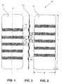
- the cleaning strip 10 for ATMs shown has a length L of 185 mm and a width B of 65 mm.
- the longitudinal direction of the cleaning strip 10 corresponds to the insertion direction x of the banknote validator of an ATM.
- the cleaning strip 10 comprises a strip 12 of a flexible carrier material such as polyvinyl chloride (PVC). a thickness of 0.15 mm.
- the strip 12 is provided on both sides with transverse strips 14, 15 of a flock coating of, for example, polyamide (PA) with the flock dimensions 1.00 mm / 3.3 dtex, wherein the first number on the length of the individual fibers and the second count on the density of the flock points.
- PVC polyvinyl chloride
- PA polyamide
- a flock coating or flocking is the application of flock fibers to a surface.
- the surface areas to be flocked are pretreated with an adhesive after pretreatment.
- the initially randomly arranged flock fibers are aligned in an electrostatic field and directed by this on the surface.
- the adhesive is allowed to cure and obtains a uniform pile with fibers protruding substantially perpendicularly from the surface.
- the flock coating transverse strips 14, 15 have, for example, a width d of 9 mm and a spacing between adjacent transverse strips of 15 mm.
- five horizontal stripes 14 are arranged on the front side and five horizontal stripes 15 on the rear side of the strip 12, wherein the transverse stripes 14 on the front face are offset from one another in the longitudinal direction of the strip 12 relative to the transverse stripes 15 on the rear side the transverse strips 14 lie on the front side between the transverse strips 15 on the back and vice versa.
- the height h of the transverse strips 14, 15 from the flock coating corresponds approximately to the length of the individual flock fibers protruding from the surface of the strip 12 of carrier material, ie in the present example about 1 mm.
- One in the FIGS. 4 to 6 illustrated cleaning card 20 for credit card machines corresponds in its construction substantially to the previously described cleaning strip 10 for ATMs and has a the dimensions of a credit card corresponding length L of, for example, 85 mm and a width B of, for example, 54 mm.
- the longitudinal direction of the cleaning card 20 corresponds to the insertion direction x of the plug-in reader of a credit card machine.
- the cleaning card 20 comprises a card or strip 22 of a carrier material such as polyvinyl chloride (PVC) a thickness of 0.3 mm, for example.
- the strip 22 is on both sides with horizontal stripes 24, 25 of a flock coating of, for example, polyamide (PA) with the flock dimensions 1.00 mm / 3.3 dtex provided.
- PVC polyvinyl chloride
- PA polyamide
- the flock coating transverse strips 24, 25 have, for example, a width d of 9 mm and a spacing between adjacent transverse strips of 12 mm.
- each four transverse strips 24 are arranged on the front side and three transverse strips 25 on the back of the card or strip 22, wherein the transverse strips 24 on the front opposite the transverse strips 25 on the back in the longitudinal direction of the strip 22 offset from each other are that the transverse strips 24 are located on the front side between the horizontal stripes 25 on the back and vice versa.
- the height h of the transverse strips 24, 25 from the flock coating corresponds approximately to the length of the individual flock fibers protruding from the surface of the strip 22 of carrier material, ie in the present example about 1 mm.
- Fig. 7 shows the arrangement of an adhesive layer 26 on the strip 22 fixed as a carrier material flock fibers 28 in a horizontal strip 24 in cleaning a magnetic head 30 of the card reader of a credit card machine.
- the brushing effect of the flock coating results in effective cleaning.
- the excellent dirt absorption of the flock prevents the mere spreading of the dirt inside the card reader.
- the particles are taken up by the fibers and removed as the card is removed.
- the flock coating of the transverse strips 14, 15 and 24, 25 may be impregnated with a cleaning agent.
- the wet cleaning strips or cards 10, 20 are stored in a fluid-tight bag until ready for use.
- the parts to be cleaned by a cleaning strip 10 for ATMs mainly relate to transport rollers and belts, sensors and reference surfaces, the parts to be cleaned by a cleaning card 20 for credit card machines, especially transport rollers, magnetic head sensors and chips.
- the longitudinal direction of the cleaning strip or the cleaning card always corresponds to the machine direction or the insertion direction, i. it corresponds to the longitudinal direction of the banknotes or credit cards which are usually likewise to be inserted in the longitudinal direction into the corresponding money or credit card machines.
- the cleaning strips and cards are also inserted transversely to its longitudinal direction, in each case, the horizontal stripes on the cleaning strips and cards are arranged transversely to the machine or insertion direction.
- the arrangement of flocked strips on the cleaning strips and cards, the width of the horizontal stripes, the distance between the horizontal stripes, the length of the flock fibers and the flock density, the chemical composition of the flock, the structure of the strips and cards and the composition of the substrates used is not limited to the embodiments described above and exemplified in the drawing.
Landscapes
- Physics & Mathematics (AREA)
- General Physics & Mathematics (AREA)
- Engineering & Computer Science (AREA)
- Theoretical Computer Science (AREA)
- Feeding Of Articles By Means Other Than Belts Or Rollers (AREA)
- Credit Cards Or The Like (AREA)
Description
- Die Erfindung betrifft einen Reinigungsstreifen oder -karte nach dem Oberbegriff des Anspruchs 1.
- Reinigungsstreifen oder -karten für Automatensysteme mit Kartenleser und Banknotenprüfer mit Durchzugsleser, mechanischem Steckleser oder Leser mit motorischem Einzug sind bekannt. Ein bekanntes Streifenmaterial besteht aus einem gegebenenfalls mit einem Reinigungsmittel getränkten Zellstoffvlies. Bekannt ist auch eine Reinigungskarte mit einer vollflächigen Flockbeschichtung sowie einer Flockbeschichtung in der Art eines Backsteinmauer-Musters.
- Die
US 2005/0266211 A1 offenbart eine Reinigungskarte aus einem Vliesstoff mit auf beiden Seiten der Karte aus der Kartenebene aufragenden, als Reinigungsflächen dienenden Erhebungen. - Aus der
WO 2007/016512 A2 ist eine Reinigungskarte aus einem flexiblen Kunststoffmaterial, wie beispielsweise Polyethylen oder Polypropylen, bekannt. Auf beiden Seiten der Karte ragen bogenförmige Abschnitte als Reinigungsflächen aus der Kartenebene auf.
Ein Reinigungsstreifen der eingangs genannten Art ist aus derDE 20 2005 016 573 U1 bekannt. - Mit den bekannten Reinigungsstreifen und -karten lassen sich die Kartenleser und Banknotenprüfer von Geld- und Kreditkartenautomaten ohne Mehraufwand nicht immer befriedigend reinigen, so dass vermehrt mit Automatenausfällen zu rechnen ist.
- Der Erfindung liegt die Aufgabe zugrunde, einen Reinigungsstreifen oder eine Reinigungskarte der eingangs genannten Art mit verbesserter Reinigungswirkung zu schaffen. Zudem soll der Reinigungsstreifen oder die Reinigungskarte einfach und sicher handhabbar sein.
- Zur erfindungsgemässen Lösung der Aufgabe führt ein Reinigungsstreifen oder eine Reinigungskarte mit den Merkmalen des Anspruchs 1.
- Damit die zu reinigenden Geräte mit möglichst wenig Aufwand wirkungsvoll gereinigt werden können, sind die Querstreifen auf beiden Oberflächen bzw. auf der Vorder- und Rückseite des Streifens angeordnet.
- Bevorzugt weisen die Querstreifen eine Breite von 5 bis 15 mm, vorzugsweise 8 bis 12 mm und einen gegenseitigen Abstand von 5 bis 20 mm, vorzugsweise 8 bis 18 mm, auf.
- Bei dem erfindungsgemässen Reinigungsstreifens oder der Reinigungskarte liegen die auf der einen Seite des Streifens angeordneten Querstreifen zwischen den auf der anderen Seite des Streifens angeordneten Querstreifen.
- Weitere Vorteile, Merkmale und Einzelheiten der Erfindung ergeben sich aus der nachfolgenden Beschreibung bevorzugter Ausführungsbeispiele sowie anhand der Zeichnung; diese zeigt schematisch in
- Fig. 1
- die Draufsicht auf die Vorderseite eines Reinigungsstreifens für Geldautomaten;
- Fig. 2
- die Draufsicht auf die Rückseite des Reinigungsstreifens von
Fig. 1 ; - Fig. 3
- den Längsschnitt durch den Reinigungsstreifen von
Fig. 1 nach deren Linie I-I; - Fig. 4
- die Draufsicht auf die Vorderseite einer Reinigungskarte für Kreditkartenautomaten;
- Fig. 5
- die Draufsicht auf die Rückseite der Reinigungskarte von
Fig. 4 ; - Fig. 6
- den Längsschnitt durch die Reinigungskarte von
Fig. 4 nach deren Linie II-II; - Fig. 7
- einen Längsschnitt durch einen Teil einer Reinigungskarte für Kreditkartenautomaten während eines Reinigungsvorgangs in vergrösserter Darstellung.
- Ein in den
Figuren 1 bis 3 dargestellter Reinigungsstreifen 10 für Geldautomaten weist beispielsweise eine Länge L von 185 mm und eine Breite B von 65 mm auf. Im gezeigten Beispiel entspricht die Längsrichtung des Reinigungsstreifens 10 der Einschubrichtung x des Banknotenprüfers eines Geldautomaten. Der Reinigungsstreifen 10 umfasst einen Streifen 12 aus einem flexiblen Trägermaterial aus z.B. Polyvinylchlorid (PVC). einer Dicke von 0.15 mm. Der Streifen 12 ist beidseitig mit Querstreifen 14, 15 aus einer Flockbeschichtung aus beispielsweise Polyamid (PA) mit den Flock-Dimensionen 1.00 mm / 3.3 dtex versehen, wobei die erste Zahl auf die Länge der einzelnen Fasern und die zweite Zähl auf die Dichte des Flocks verweist. - Unter einer Flockbeschichtung bzw. Beflockung versteht man den Auftrag von Flockfasem auf eine Oberfläche. Hierfür werden die zu beflockenden Oberflächenbereiche nach einer Vorbehandlung mit einem Klebstoff belegt. Die zunächst regellos angeordneten Flockfasern werden in einem elektrostatischen Feld ausgerichtet und durch dieses auf die Oberfläche gelenkt. Anschliessend lässt man den Klebstoff aushärten und erhält einen gleichmässigen Flor mit im Wesentlichen senkrecht von der Oberfläche abragenden Fasern.
- Die Querstreifen 14, 15 aus Flockbeschichtung weisen beispielsweise eine Breite d von 9 mm und einen Abstand zwischen benachbarten Querstreifen von 15 mm auf. Im gezeigten Beispiel sind je fünf Querstreifen 14 auf der Vorderseite und je fünf Querstreifen 15 auf der Rückseite des Streifens 12 angeordnet, wobei die Querstreifen 14 auf der Vorderseite gegenüber den Querstreifen 15 auf der Rückseite in Längsrichtung des Streifens 12 so gegeneinander versetzt angeordnet sind, dass die Querstreifen 14 auf der Vorderseite jeweils zwischen den Querstreifen 15 auf der Rückseite und umgekehrt liegen. Die Höhe h der Querstreifen 14, 15 aus der Flockbeschichtung entspricht etwa der Länge der einzelnen, von der Oberfläche des Streifen 12 aus Trägermaterial abragenden Flockfasern, im vorliegenden Beispiel also etwa 1 mm.
- Eine in den
Figuren 4 bis 6 dargestellte Reinigungskarte 20 für Kreditkartenautomaten entspricht in ihrem Aufbau im Wesentlichen dem vorgängig beschriebenen Reinigungsstreifen 10 für Geldautomaten und weist eine den Abmessungen einer Kreditkarte entsprechende Länge L von beispielsweise 85 mm und eine Breite B von beispielsweise 54 mm auf. Im gezeigten Beispiel entspricht die Längsrichtung der Reinigungskarte 20 der Einschubrichtung x des Stecklesers eines Kreditkartenautomaten. Die Reinigungskarte 20 umfasst eine Karte oder einen Streifen 22 aus einem Trägermaterial aus z.B. Polyvinylchlorid (PVC) einer Dicke von z.B. 0.3 mm. Der Streifen 22 ist beidseitig mit Querstreifen 24, 25 aus einer Flockbeschichtung aus beispielsweise Polyamid (PA) mit den Flock-Dimensionen 1.00 mm / 3.3 dtex versehen. - Die Querstreifen 24, 25 aus Flockbeschichtung weisen beispielsweise eine Breite d von 9 mm und einen Abstand zwischen benachbarten Querstreifen von 12 mm auf. Im gezeigten Beispiel sind je vier Querstreifen 24 auf der Vorderseite und je drei Querstreifen 25 auf der Rückseite der Karte oder des Streifens 22 angeordnet, wobei die Querstreifen 24 auf der Vorderseite gegenüber den Querstreifen 25 auf der Rückseite in Längsrichtung des Streifens 22 so gegeneinander versetzt angeordnet sind, dass die Querstreifen 24 auf der Vorderseite jeweils zwischen den Querstreifen 25 auf der Rückseite und umgekehrt liegen. Die Höhe h der Querstreifen 24, 25 aus der Flockbeschichtung entspricht etwa der Länge der einzelnen, von der Oberfläche des Streifen 22 aus Trägermaterial abragenden Flockfasern, im vorliegenden Beispiel also etwa 1 mm.
-
Fig. 7 zeigt die Anordnung der über eine Klebstoffschicht 26 auf dem Streifen 22 als Trägermaterial fixierten Flock-Fasern 28 in einem Querstreifen 24 beim Reinigen eines Magnetkopfes 30 des Kartenlesers eines Kreditkartenautomaten. Dank Bürstenwirkung der Flockbeschichtung ergibt sich eine effektive Reinigung. Die hervorragende Schmutzaufnahme des Flocks verhindert das blosse Verteilen des Schmutzes im Innern des Kartenlesers. Die Partikel werden durch die Fasern aufgenommen und mit dem Herausnehmen der Karte entfernt. - Zur Erhöhung der Reinigungswirkung kann die Flockbeschichtung der Querstreifen 14, 15 bzw. 24, 25 mit einem Reinigungsmittel getränkt sein. In diesem Fall werden die feuchten Reinigungsstreifen oder -karten 10, 20 bis zu ihrem Gebrauch in einem fluiddichten Beutel aufbewahrt.
- Die von einem Reinigungsstreifen 10 für Geldautomaten zu reinigenden Teile betreffen vor allem Transportrollen und -bänder, Sensoren und Referenzflächen, die von einer Reinigungskarte 20 für Kreditkartenautomaten zu reinigenden Teile vor allem Transportrollen, Sensoren Magnetkköpfe und Chips.
- In den dargestellten Beispielen entspricht die Längsrichtung des Reinigungsstreifens oder der Reinigungskarte immer der Automatenrichtung bzw. der Einschubrichtung, d.h. sie entspricht der Längsrichtung der üblicherweise ebenfalls in ihrer Längsrichtung in die entsprechenden Geld- oder Kreditkartenautomaten einzuschiebenden Banknoten oder Kreditkarten. Bei Automaten mit quer zu ihrer Längsrichtung einzuschiebenden Banknoten oder Kreditkarten werden die Reinigungsstreifen und -karten ebenfalls quer zu ihrer Längsrichtung eingeschoben, wobei in jedem Fall die Querstreifen auf den Reinigungsstreifen und -karten quer zur Automaten- bzw. Einschubrichtung angeordnet sind.
- Die Anordnung der Querstreifen aus Flock auf den Reinigungsstreifen und -karten, die Breite der Querstreifen, der Abstand zwischen den Querstreifen, die Länge der Flockfasern und die Flockdichte, die chemische Zusammensetzung des Flocks, der Aufbau der Streifen und Karten und die Zusammensetzung der verwendeten Trägermaterialien ist nicht auf die vorstehend beschriebenen und in der Zeichnung beispielhaft dargestellten Ausführungsformen beschränkt.
-
- 10
- Reinigungsstreifen für Geldautomaten
- 12
- Streifen aus Trägermaterial
- 14, 15
- Querstreifen aus Flockbeschichtung
- 20
- Reinigungskarte für Kreditkarten-Automaten
- 22
- Streifen aus Trägermaterial
- 24, 25
- Querstreifen aus Flockbeschichtung
- 26
- Klebstoffschicht
- 28
- Flockfaser
- 30
- Magnetkopf
- L
- Länge von 10 bzw. 20
- B
- Breite von 10 bzw. 20
- d
- Breite von 14, 15 bzw. 24, 25
- e
- Abstand 14-14, 15-15 bzw. 24-24, 25-25
- x
- Automatenrichtung
- h
- Höhe der Querstreifen bzw. Flockfasern
Claims (4)
- Reinigungsstreifen oder -karte für Geld- und Kreditkarten-Automaten, mit einem mit Flockfasern (28) beschichteten Streifen (12, 22) aus einem Trägermaterial, wobei zwei einander gegenüberliegende Streifenkanten eine Automatenrichtung (x) definieren und die quer zu einer Einschubrichtung in einen Geld- und Kreditkarten-Automaten gemessene Breite des Streifens (12, 22) im wesentlichen der Länge einer Seitenkante einer zur Verwendung in einem zu reinigenden Geld- und Kreditkarten-Automaten geeigneten Banknote oder Kreditkarte entspricht, wobei der Streifen (12, 22) auf wenigstens einer seiner Oberflächen wenigstens drei quer zur Automatenrichtung (x) in Abstand zueinander angeordnete, mit einer Beschichtung aus Flockfasern (28) versehene Querstreifen (14, 15; 24, 25) aufweist, wobei die Querstreifen (14, 15; 24, 25) auf beiden Oberflächen des Streifens (12, 22) angeordnet sind, dadurch gekennzeichnet, dass
die auf der einen Oberfläche des Streifens (12, 22) angeordneten Querstreifen (14, 24) zwischen den auf der anderen Oberfläche des Streifens (12, 22) angeordneten Querstreifen (15, 25) liegen. - Reinigungsstreifen oder -karte nach Anspruch 1, dadurch gekennzeichnet, dass die Querstreifen (14, 15; 24, 25) eine Breite (d) von 5 bis 15 mm, vorzugsweise 8 bis 12 mm, aufweisen.
- Reinigungsstreifen oder -karte nach Anspruch 1 oder 2, dadurch gekennzeichnet, dass die Querstreifen (14, 15; 24, 25) einen gegenseitigen Abstand (e) von 5 bis 20 mm, vorzugsweise 8 bis 18 mm, aufweisen.
- Beutel, dadurch gekennzeichnet, dass der Beutel fluiddicht ist und dass Reinigungsstreifen oder -karten nach einem der Ansprüche 1 bis 3 darin aufbewahrt sind, wobei die Reinigungsstreifen oder -karten (10, 20) mit einem Reinigungsmittel getränkt sind.
Applications Claiming Priority (2)
| Application Number | Priority Date | Filing Date | Title |
|---|---|---|---|
| CH00523/07A CH698810B1 (de) | 2007-04-02 | 2007-04-02 | Reinigungselement für Geld- und Kreditkartenautomaten. |
| PCT/CH2008/000116 WO2008119194A1 (de) | 2007-04-02 | 2008-03-18 | Reinigungsstreifen für geld- und kreditkartenautomaten |
Publications (2)
| Publication Number | Publication Date |
|---|---|
| EP2140404A1 EP2140404A1 (de) | 2010-01-06 |
| EP2140404B1 true EP2140404B1 (de) | 2016-11-30 |
Family
ID=38787741
Family Applications (1)
| Application Number | Title | Priority Date | Filing Date |
|---|---|---|---|
| EP08714766.6A Active EP2140404B1 (de) | 2007-04-02 | 2008-03-18 | Reinigungsstreifen für geld- und kreditkartenautomaten |
Country Status (5)
| Country | Link |
|---|---|
| US (1) | US20100119765A1 (de) |
| EP (1) | EP2140404B1 (de) |
| CH (1) | CH698810B1 (de) |
| ES (1) | ES2616876T3 (de) |
| WO (1) | WO2008119194A1 (de) |
Families Citing this family (11)
| Publication number | Priority date | Publication date | Assignee | Title |
|---|---|---|---|---|
| CH702256A2 (de) * | 2009-11-24 | 2011-05-31 | Ecs Ag | Verfahren zur Reinigung von Sensoren eines Münzprüf-, Zähl- und Sortiergerätes und Reinigungsmünze zur Durchführung des Verfahrens. |
| AU2017301041B2 (en) * | 2016-07-19 | 2022-07-28 | Dustoss Ltd | Device and method for cleaning solar panel arrays |
| CN107442520A (zh) * | 2017-08-04 | 2017-12-08 | 恒银金融科技股份有限公司 | 自动存取款机清理通道的方法及清理机构 |
| US10189650B1 (en) | 2017-09-25 | 2019-01-29 | Kicteam, Inc. | Card for cleaning printed media transport system and method of using same |
| WO2019060868A1 (en) | 2017-09-25 | 2019-03-28 | Kicteam, Inc. | MOVING CARD FOR CLEANING A PRINTED MEDIA TRANSPORT SYSTEM AND METHOD OF USING THE SAME |
| US10839270B2 (en) | 2017-09-25 | 2020-11-17 | Kicteam, Inc. | Card for cleaning printed media transport system and method of using same |
| US10307796B2 (en) | 2017-09-25 | 2019-06-04 | Kicteam, Inc. | Card for cleaning printed media transport system and method of using same |
| US11410003B2 (en) | 2017-09-25 | 2022-08-09 | Kicteam, Inc. | Movable card with handle for cleaning printed media transport system and method of using same |
| US11110492B2 (en) * | 2018-06-15 | 2021-09-07 | Kicteam, Inc. | Plunger card for cleaning currency handling device |
| CA3205644C (en) | 2021-02-12 | 2025-05-13 | Kicteam, Inc. | SMART CARD READER CLEANING TOOL |
| US12496621B2 (en) * | 2023-03-13 | 2025-12-16 | Kicteam, Inc. | Cleaning card with deformable cleaning elements for media transport device |
Family Cites Families (13)
| Publication number | Priority date | Publication date | Assignee | Title |
|---|---|---|---|---|
| US5153964A (en) * | 1990-01-12 | 1992-10-13 | Norman J. Olson | Machine optics and paper path cleaner |
| FI510U1 (fi) * | 1992-10-16 | 1993-02-11 | Markku Isoaho | Rengoeringskort |
| CH693757A5 (de) * | 1997-03-29 | 2004-01-15 | Ecs Ag | Reinigungskarte fuer Magnetspur-, Chipkarten-, Schr eib- und Lesegeraete sowie Verfahren zur Herstellung derselben. |
| JPH11265504A (ja) * | 1998-01-16 | 1999-09-28 | Mitsubishi Rayon Co Ltd | 磁気ヘッドクリーニングカード |
| JPH11272818A (ja) * | 1998-03-18 | 1999-10-08 | Norio Nakajima | カード処理機の清掃用カード |
| US6243908B1 (en) * | 1998-04-09 | 2001-06-12 | Unisys Corporation | Track clearance card and methods of making and using the same |
| JP2000090321A (ja) * | 1998-09-14 | 2000-03-31 | Nippon Conlux Co Ltd | 紙幣識別装置用クリーニングシート |
| JP3629430B2 (ja) * | 1998-09-28 | 2005-03-16 | ヴィンコール ニクスドルフ ゲゼルシャフト ミット ベシュレンクテル ハフツング ウント コンパニー コマンディートゲゼルシャフト | 磁気トラックおよびチップカード書込み/読出し装置のためのクリーニングカード、並びに該クリーニングカードを製造するための方法 |
| US7732040B2 (en) * | 2004-05-28 | 2010-06-08 | Enefco International, Inc. | Patterned cleaning card and method of manufacturing same |
| US7540055B1 (en) * | 2005-06-14 | 2009-06-02 | Enefco International, Inc. | Cleaning cards for internal surfaces of machine components |
| US7846534B2 (en) * | 2005-08-01 | 2010-12-07 | Enefco International, Inc. | Cleaning cards with angled cleaning surfaces |
| DE202005016573U1 (de) * | 2005-10-20 | 2006-01-05 | Jfa Jenner Flock-Applikationen E.K. | Reinigungselement |
| DE102007016949A1 (de) * | 2006-04-13 | 2007-10-25 | Ostthüringische Materialprüfgesellschaft Für Textil Und Kunststoffe Mbh | Reinigungskarte |
-
2007
- 2007-04-02 CH CH00523/07A patent/CH698810B1/de not_active IP Right Cessation
-
2008
- 2008-03-18 WO PCT/CH2008/000116 patent/WO2008119194A1/de not_active Ceased
- 2008-03-18 EP EP08714766.6A patent/EP2140404B1/de active Active
- 2008-03-18 US US12/594,402 patent/US20100119765A1/en not_active Abandoned
- 2008-03-18 ES ES08714766.6T patent/ES2616876T3/es active Active
Also Published As
| Publication number | Publication date |
|---|---|
| CH698810B1 (de) | 2009-10-30 |
| WO2008119194A1 (de) | 2008-10-09 |
| US20100119765A1 (en) | 2010-05-13 |
| ES2616876T3 (es) | 2017-06-14 |
| EP2140404A1 (de) | 2010-01-06 |
Similar Documents
| Publication | Publication Date | Title |
|---|---|---|
| EP2140404B1 (de) | Reinigungsstreifen für geld- und kreditkartenautomaten | |
| DE60031415T2 (de) | Reinigungsgerät mit vorrichtungen zum befestigen eines tuches | |
| DE60123614T2 (de) | Gegenstand zum reinigen | |
| DE3004444A1 (de) | Fluessigkeit aufnehmendes textilerzeugnis | |
| DE4314046A1 (de) | Verfahren und Vorrichtung zum Entfernen von an Oberflächen anhaftenden Partikeln durch ein Wischelement | |
| DE69518906T2 (de) | Material zum Herstellen von Monatsbinden und absorbierende Gegenstände, die mit diesem Material hergestellt sind | |
| DE69806228T2 (de) | Verfahren und vorrichtung zur herstellung von textilen produkten und erhaltene textile produkte | |
| DE10341399A1 (de) | Verfahren zur Beschichtung einer Teppichrohware mittels einer Breitschlitzdüse | |
| EP1778553A1 (de) | Sicherheitsbeutel | |
| DE102007062122A1 (de) | Sensor zur Prüfung von Wertdokumenten | |
| DE2648716C3 (de) | Teppichzwischenlage | |
| DE102010025217A1 (de) | Filterwerkstoff für ein Filterelement und Filterelement | |
| EP3617353B1 (de) | Vliesleger mit einem abliefertransportband | |
| EP3360993B1 (de) | Wegwerfbare absorbierende flächenschutzmatte | |
| DE202009018620U1 (de) | Reinigungsbezug | |
| DE29924983U1 (de) | Polstoff, sowie Filterbelag und Farbroller aus diesem Polstoff | |
| DE102010063015B4 (de) | Vorrichtung und Verfahren zum Aufbringen von Melierfasern auf ein Substrat | |
| EP1777015A1 (de) | Reinigungselement | |
| DE3643380C2 (de) | ||
| DE10361339B4 (de) | Kosmetisches Wattepad und Verfahren zum Herstellen eines kosmetischen Wattepads | |
| EP1818440A1 (de) | Waschmaschinentrommel | |
| DE2923286A1 (de) | Antistatische geflechte und gegenstaende, welche diese geflechte enthalten | |
| EP2325811A1 (de) | Verfahren zur Reinigung von Sensoren eines Münzprüf-, Zähl- und Sortiergerätes und Reinigungsmünze zur Durchführung des Verfahrens | |
| DE102014008088B4 (de) | Mehrwegflachmopp, Reinigungseinheit und Verfahren zum Tränken von Mehrwegflachmopps | |
| EP2014814B1 (de) | Bodenmatte aus flüssigkeitsabsorbierendem Vliesstoff |
Legal Events
| Date | Code | Title | Description |
|---|---|---|---|
| PUAI | Public reference made under article 153(3) epc to a published international application that has entered the european phase |
Free format text: ORIGINAL CODE: 0009012 |
|
| 17P | Request for examination filed |
Effective date: 20091016 |
|
| AK | Designated contracting states |
Kind code of ref document: A1 Designated state(s): AT BE BG CH CY CZ DE DK EE ES FI FR GB GR HR HU IE IS IT LI LT LU LV MC MT NL NO PL PT RO SE SI SK TR |
|
| DAX | Request for extension of the european patent (deleted) | ||
| 17Q | First examination report despatched |
Effective date: 20110301 |
|
| GRAP | Despatch of communication of intention to grant a patent |
Free format text: ORIGINAL CODE: EPIDOSNIGR1 |
|
| INTG | Intention to grant announced |
Effective date: 20160627 |
|
| GRAS | Grant fee paid |
Free format text: ORIGINAL CODE: EPIDOSNIGR3 |
|
| GRAA | (expected) grant |
Free format text: ORIGINAL CODE: 0009210 |
|
| AK | Designated contracting states |
Kind code of ref document: B1 Designated state(s): AT BE BG CH CY CZ DE DK EE ES FI FR GB GR HR HU IE IS IT LI LT LU LV MC MT NL NO PL PT RO SE SI SK TR |
|
| REG | Reference to a national code |
Ref country code: CH Ref legal event code: EP Ref country code: GB Ref legal event code: FG4D Free format text: NOT ENGLISH |
|
| REG | Reference to a national code |
Ref country code: AT Ref legal event code: REF Ref document number: 850411 Country of ref document: AT Kind code of ref document: T Effective date: 20161215 |
|
| REG | Reference to a national code |
Ref country code: IE Ref legal event code: FG4D Free format text: LANGUAGE OF EP DOCUMENT: GERMAN |
|
| REG | Reference to a national code |
Ref country code: DE Ref legal event code: R096 Ref document number: 502008014838 Country of ref document: DE |
|
| PG25 | Lapsed in a contracting state [announced via postgrant information from national office to epo] |
Ref country code: LV Free format text: LAPSE BECAUSE OF FAILURE TO SUBMIT A TRANSLATION OF THE DESCRIPTION OR TO PAY THE FEE WITHIN THE PRESCRIBED TIME-LIMIT Effective date: 20161130 |
|
| REG | Reference to a national code |
Ref country code: FR Ref legal event code: PLFP Year of fee payment: 10 |
|
| REG | Reference to a national code |
Ref country code: LT Ref legal event code: MG4D |
|
| REG | Reference to a national code |
Ref country code: NL Ref legal event code: MP Effective date: 20161130 |
|
| PG25 | Lapsed in a contracting state [announced via postgrant information from national office to epo] |
Ref country code: NO Free format text: LAPSE BECAUSE OF FAILURE TO SUBMIT A TRANSLATION OF THE DESCRIPTION OR TO PAY THE FEE WITHIN THE PRESCRIBED TIME-LIMIT Effective date: 20170228 Ref country code: LT Free format text: LAPSE BECAUSE OF FAILURE TO SUBMIT A TRANSLATION OF THE DESCRIPTION OR TO PAY THE FEE WITHIN THE PRESCRIBED TIME-LIMIT Effective date: 20161130 Ref country code: SE Free format text: LAPSE BECAUSE OF FAILURE TO SUBMIT A TRANSLATION OF THE DESCRIPTION OR TO PAY THE FEE WITHIN THE PRESCRIBED TIME-LIMIT Effective date: 20161130 Ref country code: GR Free format text: LAPSE BECAUSE OF FAILURE TO SUBMIT A TRANSLATION OF THE DESCRIPTION OR TO PAY THE FEE WITHIN THE PRESCRIBED TIME-LIMIT Effective date: 20170301 |
|
| PG25 | Lapsed in a contracting state [announced via postgrant information from national office to epo] |
Ref country code: FI Free format text: LAPSE BECAUSE OF FAILURE TO SUBMIT A TRANSLATION OF THE DESCRIPTION OR TO PAY THE FEE WITHIN THE PRESCRIBED TIME-LIMIT Effective date: 20161130 Ref country code: HR Free format text: LAPSE BECAUSE OF FAILURE TO SUBMIT A TRANSLATION OF THE DESCRIPTION OR TO PAY THE FEE WITHIN THE PRESCRIBED TIME-LIMIT Effective date: 20161130 Ref country code: PL Free format text: LAPSE BECAUSE OF FAILURE TO SUBMIT A TRANSLATION OF THE DESCRIPTION OR TO PAY THE FEE WITHIN THE PRESCRIBED TIME-LIMIT Effective date: 20161130 |
|
| REG | Reference to a national code |
Ref country code: ES Ref legal event code: FG2A Ref document number: 2616876 Country of ref document: ES Kind code of ref document: T3 Effective date: 20170614 |
|
| PG25 | Lapsed in a contracting state [announced via postgrant information from national office to epo] |
Ref country code: NL Free format text: LAPSE BECAUSE OF FAILURE TO SUBMIT A TRANSLATION OF THE DESCRIPTION OR TO PAY THE FEE WITHIN THE PRESCRIBED TIME-LIMIT Effective date: 20161130 |
|
| PG25 | Lapsed in a contracting state [announced via postgrant information from national office to epo] |
Ref country code: CZ Free format text: LAPSE BECAUSE OF FAILURE TO SUBMIT A TRANSLATION OF THE DESCRIPTION OR TO PAY THE FEE WITHIN THE PRESCRIBED TIME-LIMIT Effective date: 20161130 Ref country code: SK Free format text: LAPSE BECAUSE OF FAILURE TO SUBMIT A TRANSLATION OF THE DESCRIPTION OR TO PAY THE FEE WITHIN THE PRESCRIBED TIME-LIMIT Effective date: 20161130 Ref country code: RO Free format text: LAPSE BECAUSE OF FAILURE TO SUBMIT A TRANSLATION OF THE DESCRIPTION OR TO PAY THE FEE WITHIN THE PRESCRIBED TIME-LIMIT Effective date: 20161130 Ref country code: DK Free format text: LAPSE BECAUSE OF FAILURE TO SUBMIT A TRANSLATION OF THE DESCRIPTION OR TO PAY THE FEE WITHIN THE PRESCRIBED TIME-LIMIT Effective date: 20161130 Ref country code: EE Free format text: LAPSE BECAUSE OF FAILURE TO SUBMIT A TRANSLATION OF THE DESCRIPTION OR TO PAY THE FEE WITHIN THE PRESCRIBED TIME-LIMIT Effective date: 20161130 |
|
| PG25 | Lapsed in a contracting state [announced via postgrant information from national office to epo] |
Ref country code: IT Free format text: LAPSE BECAUSE OF FAILURE TO SUBMIT A TRANSLATION OF THE DESCRIPTION OR TO PAY THE FEE WITHIN THE PRESCRIBED TIME-LIMIT Effective date: 20161130 Ref country code: BG Free format text: LAPSE BECAUSE OF FAILURE TO SUBMIT A TRANSLATION OF THE DESCRIPTION OR TO PAY THE FEE WITHIN THE PRESCRIBED TIME-LIMIT Effective date: 20170228 |
|
| REG | Reference to a national code |
Ref country code: DE Ref legal event code: R097 Ref document number: 502008014838 Country of ref document: DE |
|
| PLBE | No opposition filed within time limit |
Free format text: ORIGINAL CODE: 0009261 |
|
| STAA | Information on the status of an ep patent application or granted ep patent |
Free format text: STATUS: NO OPPOSITION FILED WITHIN TIME LIMIT |
|
| 26N | No opposition filed |
Effective date: 20170831 |
|
| PG25 | Lapsed in a contracting state [announced via postgrant information from national office to epo] |
Ref country code: SI Free format text: LAPSE BECAUSE OF FAILURE TO SUBMIT A TRANSLATION OF THE DESCRIPTION OR TO PAY THE FEE WITHIN THE PRESCRIBED TIME-LIMIT Effective date: 20161130 Ref country code: MC Free format text: LAPSE BECAUSE OF FAILURE TO SUBMIT A TRANSLATION OF THE DESCRIPTION OR TO PAY THE FEE WITHIN THE PRESCRIBED TIME-LIMIT Effective date: 20161130 |
|
| REG | Reference to a national code |
Ref country code: IE Ref legal event code: MM4A |
|
| PG25 | Lapsed in a contracting state [announced via postgrant information from national office to epo] |
Ref country code: LU Free format text: LAPSE BECAUSE OF NON-PAYMENT OF DUE FEES Effective date: 20170318 |
|
| PG25 | Lapsed in a contracting state [announced via postgrant information from national office to epo] |
Ref country code: IE Free format text: LAPSE BECAUSE OF NON-PAYMENT OF DUE FEES Effective date: 20170318 |
|
| REG | Reference to a national code |
Ref country code: BE Ref legal event code: MM Effective date: 20170331 |
|
| REG | Reference to a national code |
Ref country code: FR Ref legal event code: PLFP Year of fee payment: 11 |
|
| PG25 | Lapsed in a contracting state [announced via postgrant information from national office to epo] |
Ref country code: BE Free format text: LAPSE BECAUSE OF NON-PAYMENT OF DUE FEES Effective date: 20170331 |
|
| PG25 | Lapsed in a contracting state [announced via postgrant information from national office to epo] |
Ref country code: MT Free format text: LAPSE BECAUSE OF FAILURE TO SUBMIT A TRANSLATION OF THE DESCRIPTION OR TO PAY THE FEE WITHIN THE PRESCRIBED TIME-LIMIT Effective date: 20161130 |
|
| PG25 | Lapsed in a contracting state [announced via postgrant information from national office to epo] |
Ref country code: HU Free format text: LAPSE BECAUSE OF FAILURE TO SUBMIT A TRANSLATION OF THE DESCRIPTION OR TO PAY THE FEE WITHIN THE PRESCRIBED TIME-LIMIT; INVALID AB INITIO Effective date: 20080318 |
|
| PGFP | Annual fee paid to national office [announced via postgrant information from national office to epo] |
Ref country code: ES Payment date: 20190418 Year of fee payment: 12 |
|
| PG25 | Lapsed in a contracting state [announced via postgrant information from national office to epo] |
Ref country code: CY Free format text: LAPSE BECAUSE OF NON-PAYMENT OF DUE FEES Effective date: 20161130 |
|
| PG25 | Lapsed in a contracting state [announced via postgrant information from national office to epo] |
Ref country code: TR Free format text: LAPSE BECAUSE OF FAILURE TO SUBMIT A TRANSLATION OF THE DESCRIPTION OR TO PAY THE FEE WITHIN THE PRESCRIBED TIME-LIMIT Effective date: 20161130 |
|
| PG25 | Lapsed in a contracting state [announced via postgrant information from national office to epo] |
Ref country code: PT Free format text: LAPSE BECAUSE OF FAILURE TO SUBMIT A TRANSLATION OF THE DESCRIPTION OR TO PAY THE FEE WITHIN THE PRESCRIBED TIME-LIMIT Effective date: 20161130 |
|
| PG25 | Lapsed in a contracting state [announced via postgrant information from national office to epo] |
Ref country code: IS Free format text: LAPSE BECAUSE OF FAILURE TO SUBMIT A TRANSLATION OF THE DESCRIPTION OR TO PAY THE FEE WITHIN THE PRESCRIBED TIME-LIMIT Effective date: 20170330 |
|
| REG | Reference to a national code |
Ref country code: ES Ref legal event code: FD2A Effective date: 20210804 |
|
| PG25 | Lapsed in a contracting state [announced via postgrant information from national office to epo] |
Ref country code: ES Free format text: LAPSE BECAUSE OF NON-PAYMENT OF DUE FEES Effective date: 20200319 |
|
| P01 | Opt-out of the competence of the unified patent court (upc) registered |
Effective date: 20230504 |
|
| PGFP | Annual fee paid to national office [announced via postgrant information from national office to epo] |
Ref country code: CH Payment date: 20250401 Year of fee payment: 18 |
|
| REG | Reference to a national code |
Ref country code: CH Ref legal event code: U11 Free format text: ST27 STATUS EVENT CODE: U-0-0-U10-U11 (AS PROVIDED BY THE NATIONAL OFFICE) Effective date: 20260401 |
|
| PGFP | Annual fee paid to national office [announced via postgrant information from national office to epo] |
Ref country code: GB Payment date: 20260119 Year of fee payment: 19 |
|
| PGFP | Annual fee paid to national office [announced via postgrant information from national office to epo] |
Ref country code: DE Payment date: 20260119 Year of fee payment: 19 |
|
| PGFP | Annual fee paid to national office [announced via postgrant information from national office to epo] |
Ref country code: AT Payment date: 20260119 Year of fee payment: 19 |
|
| PGFP | Annual fee paid to national office [announced via postgrant information from national office to epo] |
Ref country code: FR Payment date: 20260119 Year of fee payment: 19 |