EP2141260A2 - Beschichtete Komponenten zur Verwendung in Umgebungen mit hoher Temperatur und Verfahren zum Bilden einer Beschichtung auf der Komponente - Google Patents
Beschichtete Komponenten zur Verwendung in Umgebungen mit hoher Temperatur und Verfahren zum Bilden einer Beschichtung auf der Komponente Download PDFInfo
- Publication number
- EP2141260A2 EP2141260A2 EP20090155923 EP09155923A EP2141260A2 EP 2141260 A2 EP2141260 A2 EP 2141260A2 EP 20090155923 EP20090155923 EP 20090155923 EP 09155923 A EP09155923 A EP 09155923A EP 2141260 A2 EP2141260 A2 EP 2141260A2
- Authority
- EP
- European Patent Office
- Prior art keywords
- constituent
- component
- coating
- agglomerates
- metal
- Prior art date
- Legal status (The legal status is an assumption and is not a legal conclusion. Google has not performed a legal analysis and makes no representation as to the accuracy of the status listed.)
- Withdrawn
Links
- 238000000576 coating method Methods 0.000 title claims abstract description 63
- 239000011248 coating agent Substances 0.000 title claims abstract description 52
- 238000000034 method Methods 0.000 title abstract description 24
- 239000000470 constituent Substances 0.000 claims abstract description 128
- 239000002245 particle Substances 0.000 claims abstract description 39
- 239000000758 substrate Substances 0.000 claims abstract description 36
- 239000000463 material Substances 0.000 claims description 23
- 239000000203 mixture Substances 0.000 claims description 22
- 229910010272 inorganic material Inorganic materials 0.000 claims description 21
- 239000011147 inorganic material Substances 0.000 claims description 21
- 239000011230 binding agent Substances 0.000 claims description 19
- 229910052751 metal Inorganic materials 0.000 claims description 12
- 239000002184 metal Substances 0.000 claims description 12
- PXHVJJICTQNCMI-UHFFFAOYSA-N Nickel Chemical compound [Ni] PXHVJJICTQNCMI-UHFFFAOYSA-N 0.000 claims description 8
- 239000000956 alloy Substances 0.000 claims description 7
- 229910045601 alloy Inorganic materials 0.000 claims description 7
- WGLPBDUCMAPZCE-UHFFFAOYSA-N Trioxochromium Chemical compound O=[Cr](=O)=O WGLPBDUCMAPZCE-UHFFFAOYSA-N 0.000 claims description 6
- 229910052946 acanthite Inorganic materials 0.000 claims description 6
- XUARKZBEFFVFRG-UHFFFAOYSA-N silver sulfide Chemical compound [S-2].[Ag+].[Ag+] XUARKZBEFFVFRG-UHFFFAOYSA-N 0.000 claims description 6
- 229940056910 silver sulfide Drugs 0.000 claims description 6
- 239000000374 eutectic mixture Substances 0.000 claims description 5
- 229910001512 metal fluoride Inorganic materials 0.000 claims description 5
- VYZAMTAEIAYCRO-UHFFFAOYSA-N Chromium Chemical compound [Cr] VYZAMTAEIAYCRO-UHFFFAOYSA-N 0.000 claims description 4
- QVQLCTNNEUAWMS-UHFFFAOYSA-N barium oxide Chemical compound [Ba]=O QVQLCTNNEUAWMS-UHFFFAOYSA-N 0.000 claims description 4
- 239000000919 ceramic Substances 0.000 claims description 4
- 239000011651 chromium Substances 0.000 claims description 4
- GNTDGMZSJNCJKK-UHFFFAOYSA-N divanadium pentaoxide Chemical compound O=[V](=O)O[V](=O)=O GNTDGMZSJNCJKK-UHFFFAOYSA-N 0.000 claims description 4
- 229910001092 metal group alloy Inorganic materials 0.000 claims description 4
- 229910044991 metal oxide Inorganic materials 0.000 claims description 4
- 150000004706 metal oxides Chemical class 0.000 claims description 4
- 229910052976 metal sulfide Inorganic materials 0.000 claims description 4
- 229910052759 nickel Inorganic materials 0.000 claims description 4
- 229910000480 nickel oxide Inorganic materials 0.000 claims description 4
- GNRSAWUEBMWBQH-UHFFFAOYSA-N oxonickel Chemical compound [Ni]=O GNRSAWUEBMWBQH-UHFFFAOYSA-N 0.000 claims description 4
- 239000010970 precious metal Substances 0.000 claims description 4
- 229910052804 chromium Inorganic materials 0.000 claims description 3
- WUKWITHWXAAZEY-UHFFFAOYSA-L calcium difluoride Chemical compound [F-].[F-].[Ca+2] WUKWITHWXAAZEY-UHFFFAOYSA-L 0.000 claims description 2
- 229910001634 calcium fluoride Inorganic materials 0.000 claims description 2
- NNLOHLDVJGPUFR-UHFFFAOYSA-L calcium;3,4,5,6-tetrahydroxy-2-oxohexanoate Chemical compound [Ca+2].OCC(O)C(O)C(O)C(=O)C([O-])=O.OCC(O)C(O)C(O)C(=O)C([O-])=O NNLOHLDVJGPUFR-UHFFFAOYSA-L 0.000 claims description 2
- 239000010941 cobalt Substances 0.000 claims description 2
- 229910017052 cobalt Inorganic materials 0.000 claims description 2
- GUTLYIVDDKVIGB-UHFFFAOYSA-N cobalt atom Chemical compound [Co] GUTLYIVDDKVIGB-UHFFFAOYSA-N 0.000 claims description 2
- OMZSGWSJDCOLKM-UHFFFAOYSA-N copper(II) sulfide Chemical compound [S-2].[Cu+2] OMZSGWSJDCOLKM-UHFFFAOYSA-N 0.000 claims description 2
- QDOXWKRWXJOMAK-UHFFFAOYSA-N dichromium trioxide Chemical compound O=[Cr]O[Cr]=O QDOXWKRWXJOMAK-UHFFFAOYSA-N 0.000 claims description 2
- 229910052981 lead sulfide Inorganic materials 0.000 claims description 2
- 229940056932 lead sulfide Drugs 0.000 claims description 2
- 229910001635 magnesium fluoride Inorganic materials 0.000 claims description 2
- ORUIBWPALBXDOA-UHFFFAOYSA-L magnesium fluoride Chemical compound [F-].[F-].[Mg+2] ORUIBWPALBXDOA-UHFFFAOYSA-L 0.000 claims description 2
- TWNQGVIAIRXVLR-UHFFFAOYSA-N oxo(oxoalumanyloxy)alumane Chemical compound O=[Al]O[Al]=O TWNQGVIAIRXVLR-UHFFFAOYSA-N 0.000 claims description 2
- BPQQTUXANYXVAA-UHFFFAOYSA-N Orthosilicate Chemical compound [O-][Si]([O-])([O-])[O-] BPQQTUXANYXVAA-UHFFFAOYSA-N 0.000 claims 1
- 239000000314 lubricant Substances 0.000 description 22
- 239000007787 solid Substances 0.000 description 20
- 239000011888 foil Substances 0.000 description 9
- 239000007788 liquid Substances 0.000 description 9
- 239000002243 precursor Substances 0.000 description 8
- 239000000843 powder Substances 0.000 description 7
- 239000002904 solvent Substances 0.000 description 7
- XLYOFNOQVPJJNP-UHFFFAOYSA-N water Substances O XLYOFNOQVPJJNP-UHFFFAOYSA-N 0.000 description 7
- 238000010586 diagram Methods 0.000 description 5
- 239000012454 non-polar solvent Substances 0.000 description 5
- 239000000126 substance Substances 0.000 description 5
- 238000009472 formulation Methods 0.000 description 4
- YXFVVABEGXRONW-UHFFFAOYSA-N Toluene Chemical compound CC1=CC=CC=C1 YXFVVABEGXRONW-UHFFFAOYSA-N 0.000 description 3
- 229910000423 chromium oxide Inorganic materials 0.000 description 3
- 229920000620 organic polymer Polymers 0.000 description 3
- 238000002360 preparation method Methods 0.000 description 3
- 150000004760 silicates Chemical class 0.000 description 3
- 229910000531 Co alloy Inorganic materials 0.000 description 2
- LFQSCWFLJHTTHZ-UHFFFAOYSA-N Ethanol Chemical compound CCO LFQSCWFLJHTTHZ-UHFFFAOYSA-N 0.000 description 2
- 239000001856 Ethyl cellulose Substances 0.000 description 2
- ZZSNKZQZMQGXPY-UHFFFAOYSA-N Ethyl cellulose Chemical compound CCOCC1OC(OC)C(OCC)C(OCC)C1OC1C(O)C(O)C(OC)C(CO)O1 ZZSNKZQZMQGXPY-UHFFFAOYSA-N 0.000 description 2
- 229910021578 Iron(III) chloride Inorganic materials 0.000 description 2
- LRHPLDYGYMQRHN-UHFFFAOYSA-N N-Butanol Chemical compound CCCCO LRHPLDYGYMQRHN-UHFFFAOYSA-N 0.000 description 2
- 239000000020 Nitrocellulose Substances 0.000 description 2
- KDLHZDBZIXYQEI-UHFFFAOYSA-N Palladium Chemical compound [Pd] KDLHZDBZIXYQEI-UHFFFAOYSA-N 0.000 description 2
- GWEVSGVZZGPLCZ-UHFFFAOYSA-N Titan oxide Chemical compound O=[Ti]=O GWEVSGVZZGPLCZ-UHFFFAOYSA-N 0.000 description 2
- 229910052784 alkaline earth metal Inorganic materials 0.000 description 2
- 239000003054 catalyst Substances 0.000 description 2
- 239000008367 deionised water Substances 0.000 description 2
- 229910021641 deionized water Inorganic materials 0.000 description 2
- 229920001249 ethyl cellulose Polymers 0.000 description 2
- 235000019325 ethyl cellulose Nutrition 0.000 description 2
- 230000001747 exhibiting effect Effects 0.000 description 2
- 239000005383 fluoride glass Substances 0.000 description 2
- 238000010438 heat treatment Methods 0.000 description 2
- RBTARNINKXHZNM-UHFFFAOYSA-K iron trichloride Chemical compound Cl[Fe](Cl)Cl RBTARNINKXHZNM-UHFFFAOYSA-K 0.000 description 2
- 238000002844 melting Methods 0.000 description 2
- 230000008018 melting Effects 0.000 description 2
- 229920001220 nitrocellulos Polymers 0.000 description 2
- 230000003647 oxidation Effects 0.000 description 2
- 238000007254 oxidation reaction Methods 0.000 description 2
- BASFCYQUMIYNBI-UHFFFAOYSA-N platinum Chemical compound [Pt] BASFCYQUMIYNBI-UHFFFAOYSA-N 0.000 description 2
- 239000002491 polymer binding agent Substances 0.000 description 2
- 238000005245 sintering Methods 0.000 description 2
- RYGMFSIKBFXOCR-UHFFFAOYSA-N Copper Chemical compound [Cu] RYGMFSIKBFXOCR-UHFFFAOYSA-N 0.000 description 1
- 229910000599 Cr alloy Inorganic materials 0.000 description 1
- GYHNNYVSQQEPJS-UHFFFAOYSA-N Gallium Chemical compound [Ga] GYHNNYVSQQEPJS-UHFFFAOYSA-N 0.000 description 1
- BQCADISMDOOEFD-UHFFFAOYSA-N Silver Chemical compound [Ag] BQCADISMDOOEFD-UHFFFAOYSA-N 0.000 description 1
- 239000004115 Sodium Silicate Substances 0.000 description 1
- 238000005411 Van der Waals force Methods 0.000 description 1
- HCHKCACWOHOZIP-UHFFFAOYSA-N Zinc Chemical compound [Zn] HCHKCACWOHOZIP-UHFFFAOYSA-N 0.000 description 1
- 239000002253 acid Substances 0.000 description 1
- 150000001342 alkaline earth metals Chemical class 0.000 description 1
- PNEYBMLMFCGWSK-UHFFFAOYSA-N aluminium oxide Inorganic materials [O-2].[O-2].[O-2].[Al+3].[Al+3] PNEYBMLMFCGWSK-UHFFFAOYSA-N 0.000 description 1
- 230000015572 biosynthetic process Effects 0.000 description 1
- -1 butanol Chemical compound 0.000 description 1
- 238000001311 chemical methods and process Methods 0.000 description 1
- 239000010949 copper Substances 0.000 description 1
- 229910052802 copper Inorganic materials 0.000 description 1
- 230000007797 corrosion Effects 0.000 description 1
- 238000005260 corrosion Methods 0.000 description 1
- 229910052593 corundum Inorganic materials 0.000 description 1
- 239000000428 dust Substances 0.000 description 1
- 150000002222 fluorine compounds Chemical class 0.000 description 1
- 229910052733 gallium Inorganic materials 0.000 description 1
- PCHJSUWPFVWCPO-UHFFFAOYSA-N gold Chemical compound [Au] PCHJSUWPFVWCPO-UHFFFAOYSA-N 0.000 description 1
- 229910052737 gold Inorganic materials 0.000 description 1
- 239000010931 gold Substances 0.000 description 1
- 229910052500 inorganic mineral Inorganic materials 0.000 description 1
- 239000011872 intimate mixture Substances 0.000 description 1
- 239000011707 mineral Substances 0.000 description 1
- 238000002156 mixing Methods 0.000 description 1
- 229910052961 molybdenite Inorganic materials 0.000 description 1
- 229910052982 molybdenum disulfide Inorganic materials 0.000 description 1
- CWQXQMHSOZUFJS-UHFFFAOYSA-N molybdenum disulfide Chemical compound S=[Mo]=S CWQXQMHSOZUFJS-UHFFFAOYSA-N 0.000 description 1
- 239000002105 nanoparticle Substances 0.000 description 1
- 230000001590 oxidative effect Effects 0.000 description 1
- 229910052763 palladium Inorganic materials 0.000 description 1
- 238000007750 plasma spraying Methods 0.000 description 1
- 229910052697 platinum Inorganic materials 0.000 description 1
- 239000002798 polar solvent Substances 0.000 description 1
- 238000007517 polishing process Methods 0.000 description 1
- 239000002244 precipitate Substances 0.000 description 1
- 230000002028 premature Effects 0.000 description 1
- 230000001737 promoting effect Effects 0.000 description 1
- 229910052761 rare earth metal Inorganic materials 0.000 description 1
- 150000002910 rare earth metals Chemical class 0.000 description 1
- 229910052702 rhenium Inorganic materials 0.000 description 1
- WUAPFZMCVAUBPE-UHFFFAOYSA-N rhenium atom Chemical compound [Re] WUAPFZMCVAUBPE-UHFFFAOYSA-N 0.000 description 1
- 238000007650 screen-printing Methods 0.000 description 1
- 238000001338 self-assembly Methods 0.000 description 1
- 229910052709 silver Inorganic materials 0.000 description 1
- 239000004332 silver Substances 0.000 description 1
- NTHWMYGWWRZVTN-UHFFFAOYSA-N sodium silicate Chemical compound [Na+].[Na+].[O-][Si]([O-])=O NTHWMYGWWRZVTN-UHFFFAOYSA-N 0.000 description 1
- 229910052911 sodium silicate Inorganic materials 0.000 description 1
- 230000003068 static effect Effects 0.000 description 1
- 229910001845 yogo sapphire Inorganic materials 0.000 description 1
- 229910052725 zinc Inorganic materials 0.000 description 1
- 239000011701 zinc Substances 0.000 description 1
Images

Classifications
-
- C—CHEMISTRY; METALLURGY
- C23—COATING METALLIC MATERIAL; COATING MATERIAL WITH METALLIC MATERIAL; CHEMICAL SURFACE TREATMENT; DIFFUSION TREATMENT OF METALLIC MATERIAL; COATING BY VACUUM EVAPORATION, BY SPUTTERING, BY ION IMPLANTATION OR BY CHEMICAL VAPOUR DEPOSITION, IN GENERAL; INHIBITING CORROSION OF METALLIC MATERIAL OR INCRUSTATION IN GENERAL
- C23C—COATING METALLIC MATERIAL; COATING MATERIAL WITH METALLIC MATERIAL; SURFACE TREATMENT OF METALLIC MATERIAL BY DIFFUSION INTO THE SURFACE, BY CHEMICAL CONVERSION OR SUBSTITUTION; COATING BY VACUUM EVAPORATION, BY SPUTTERING, BY ION IMPLANTATION OR BY CHEMICAL VAPOUR DEPOSITION, IN GENERAL
- C23C18/00—Chemical coating by decomposition of either liquid compounds or solutions of the coating forming compounds, without leaving reaction products of surface material in the coating; Contact plating
- C23C18/02—Chemical coating by decomposition of either liquid compounds or solutions of the coating forming compounds, without leaving reaction products of surface material in the coating; Contact plating by thermal decomposition
- C23C18/12—Chemical coating by decomposition of either liquid compounds or solutions of the coating forming compounds, without leaving reaction products of surface material in the coating; Contact plating by thermal decomposition characterised by the deposition of inorganic material other than metallic material
- C23C18/1204—Chemical coating by decomposition of either liquid compounds or solutions of the coating forming compounds, without leaving reaction products of surface material in the coating; Contact plating by thermal decomposition characterised by the deposition of inorganic material other than metallic material inorganic material, e.g. non-oxide and non-metallic such as sulfides, nitrides based compounds
-
- Y—GENERAL TAGGING OF NEW TECHNOLOGICAL DEVELOPMENTS; GENERAL TAGGING OF CROSS-SECTIONAL TECHNOLOGIES SPANNING OVER SEVERAL SECTIONS OF THE IPC; TECHNICAL SUBJECTS COVERED BY FORMER USPC CROSS-REFERENCE ART COLLECTIONS [XRACs] AND DIGESTS
- Y10—TECHNICAL SUBJECTS COVERED BY FORMER USPC
- Y10T—TECHNICAL SUBJECTS COVERED BY FORMER US CLASSIFICATION
- Y10T428/00—Stock material or miscellaneous articles
- Y10T428/31504—Composite [nonstructural laminate]
Definitions
- the inventive subject matter generally relates to engine components for use in high temperature environments, and more particularly relates to coatings for the components and methods of forming the coatings.
- Foil bearings may be used to support rotating components of turbine engines, turbochargers, and the like.
- a foil bearing includes a journal mounted to the rotating component and a cylindrical top foil disposed around the journal.
- the journal and top foil are configured such that when the rotating component rotates at an optimum operational speed, the foil and the journal separate from each other to form an air gap.
- pressurized air is drawn in to serve as a load support and act as a lubricant to the rotating component and surrounding static components.
- Solid lubricant coatings may be made up of a composition including inorganic constituents, such as a chromium oxide (e.g., chromic oxide, Cr 2 O 3 ), a metal binder comprising a chromium/nickel or chromium/cobalt alloy, a metal fluoride, and, optionally, a metal lubricant.
- a chromium oxide e.g., chromic oxide, Cr 2 O 3
- a metal binder comprising a chromium/nickel or chromium/cobalt alloy
- a metal fluoride e.g., a metal fluoride
- the composition may be powder-milled and then deposited on the component by high-temperature processes (e.g., greater than 800°C), such as plasma spraying, and/or applied to the component and sintered at a high temperature to impart various properties to the coating.
- high-temperature processes e.g., greater than 800°C
- plasma spraying e.g., plasma spraying
- the composition may be added to a liquid binder, which may include organic polymer constituents, and the component may be sprayed with or dipped into the liquid.
- the aforementioned processes for coating the components are effective, they may be improved.
- the high-temperature processes are typically not used for coating relatively small or thin components (e.g., components having a thickness of less than about 1.25 mm), such as the top foil, because the components may melt or sinter during processing.
- the processes are typically not used for coating components made of materials having a melting temperature below that of the processing temperatures.
- the coatings may be formed using liquid binders; however, such processes may yield coatings which may be limited to operating temperatures of less than about 350° C.
- a solid lubricant coating that may be applied to a component, such that the component may operate in temperatures in excess of about 350° C.
- a method of forming the coating which can be easily and inexpensively performed. It is also desirable for the method to be performed at temperatures that are below those which may thermally damage the component, while still allowing the solid lubricant coating to bond to the substrate surface.
- Coated components and methods of forming a coating on a component are provided.
- a coated component includes a substrate and a coating overlying the substrate, where the coating comprises a plurality of a first type of agglomerates, each agglomerate including one or more particles of a first constituent and one or more particles of a second constituent that is different from the first constituent assembled into a structure.
- the structures of a majority of the plurality of the first type of agglomerates of the coating are identical to each other.
- a coated component in another embodiment, by way of example only, includes a substrate and a coating overlying the substrate.
- the coating includes a plurality of a first type of agglomerates and a plurality of a second type of agglomerates, where each agglomerate of the plurality of the first type of agglomerates including one or more particles of a first constituent and one or more particles of a second constituent assembled into a first structure, and each agglomerate of the plurality of the second type of agglomerates including one or more particles of a third constituent and one or more particles of a fourth constituent assembled into a second structure.
- the first structures of a majority of the plurality of the first type of agglomerates of the coating are identical to each other, and the second structures of a majority of the plurality of the second type of agglomerates of the coating are identical to each other.
- the first constituent and the second constituent are different from each other, and the third constituent and the fourth constituent are different from each other.
- a method in yet another embodiment, by way of example only, includes forming a plurality of agglomerates, each agglomerate including one or more particles of a first constituent and one or more particles of a second constituent that is different from the first constituent assembled into a structure, wherein the structures of a majority of the plurality of agglomerates of the coating are identical to each other.
- the method also includes applying the plurality of agglomerates to a substrate to form the coating on the component.
- FIG. 1 is a cross section view of a component, according to an embodiment
- FIG. 2 is a close up view of a portion of the component of FIG. 1 indicated by dotted line 1, according to an embodiment
- FIG. 3 is a close up view of a portion of a component, according to another embodiment
- FIG. 4 is a simplified cross section view of an agglomerate, according to an embodiment
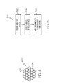
- FIG. 5 is a flow diagram of a method of forming a coating for a component, according to an embodiment
- FIG. 6 is a flow diagram of a step of the method in FIG. 5 , according to an embodiment.
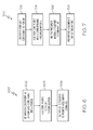
- FIG. 7 is a flow diagram of a step of the method in FIG. 5 , according to an embodiment.
- FIG. 1 is a cross section view of a component 100, according to an embodiment.
- the component 100 may be any component used in an aircraft, spacecraft, watercraft, landcraft, or any other vehicle or machine that may include components having a coating thereon.
- the component 100 may be a bearing, such as a foil bearing, journal bearing, roller bearing, and the like.
- the component 100 may be a rotating or a stationary turbine blade, airfoil, impeller, shroud, housing, strut, or other component that may be subjected to relatively high temperatures, such as those in excess of 350° C.
- the component 100 may be made up of a substrate 102 having a coating 104 thereon.
- the substrate 102 may be made of a metal, such as a nickel-based alloy, cobalt-based alloy, and the like, or other materials typically used for machine components. Although the substrate 102 of FIG. 1 is shown to have a circular cross section, substrates may have different geometrical cross-sectional shapes, in other embodiments.
- the coating 104 is shown to completely surround the periphery of substrate 102, however a coating may only partially cover the periphery of a substrate, in other embodiments.
- the coating 104 has a particular composition, and the composition is made up of particles of two or more constituents. As will be discussed in more detail below, the particles of the constituents are arranged within structures that are referred to herein as "agglomerates" 106.
- FIG. 2 is a close-up view of a portion of the coating 104 indicated in FIG. 1 by dotted line 1, according to an embodiment.
- a plurality of a first type of agglomerates 106 makes up the coating 104.
- At least a majority of the plurality of the first type of agglomerates 106 are identical in structure, in an embodiment. In another embodiment, all of the agglomerates of the plurality of the first type of agglomerates 106 are identical to each other in structure.
- FIG. 3 is a close-up view of a portion of a coating 304 on a portion of a component 300, according to another embodiment.
- three types of agglomerates 306, 308, 310 make up the coating 304.
- at least a majority of the plurality of the first type of agglomerates 306 are identical in structure
- at least a majority of the plurality of the second type of agglomerates 308 are identical in structure
- at least a majority of the plurality of the third type of agglomerates 310 are identical in structure, in an embodiment.
- all of the agglomerates of the plurality of the first type of agglomerates 306 are identical to each other in structure
- all of the agglomerates of the plurality of the second type of agglomerates 308 are identical to each other in structure
- all of the agglomerates of the plurality of the third type of agglomerates 310 are identical to each other in structure.
- the three types of agglomerates 306, 308 are shown as being substantially uniformly dispersed with respect to each other, they may not be in some embodiments.
- the first type of agglomerates 306 is shown as having particles that are larger than those of the second and third types of agglomerates 308, 310 they may alternatively be substantially identical (e.g., ⁇ 0.5 microns) in size, in other embodiments. In still other embodiments, the first type of agglomerates 306 may be smaller than the second and third types of agglomerates 308, 310. Moreover, in other embodiments, the coating 304 may be made up of two types or more than three types of agglomerates of substantially identical or varying sizes.
- FIG. 4 is a simplified, cross section view of an agglomerate 400, according to an embodiment.
- the agglomerate 400 includes several particles of a first constituent 402 and several particles of a second constituent 404.
- the particles of each of the constituents 402, 404 form a structure.
- the structure is shown as being substantially two-dimensional, it will be appreciated that structure may be three-dimensional in other embodiments.
- a first number of particles of the first constituent 402 and a second number of particles of the second constituent 404 are depicted as forming the agglomerate 400 in this embodiment, it will be appreciated that fewer or more particles of the first constituent may be included in other embodiments.
- fewer or more particles of the second constituent may be included in still other embodiments.
- all of the constituents appear to be substantially identical in size, they may not be in other embodiments.
- one constituent e.g., the first constituent 402
- another constituent e.g., the second constituent 404
- the agglomerate 400 is shown as including two different constituents 402, 404, the number of constituents in the composition of the agglomerate 400 depends on a particular formulation of the resultant coating 104, 304 ( FIGs. 1-3 ).
- the coating 104, 304 may have a composition that forms a solid film lubricant, and the composition may be composed of one or more agglomerate of one or more types including one or more constituents that make up the solid film lubricant.
- the agglomerate 400 may include more than two constituents.
- a solid film lubricant formulation may include a constituent that is a material capable of providing solid film lubricant properties to a coating.
- the constituent may be an inorganic material.
- suitable inorganic materials exhibiting such properties include, but are not limited to one or more metal sulfides, metal fluorides, and/or precious metals.
- suitable metal sulfides include, but are not limited to MoS 2 .
- suitable metal fluorides include, but are not limited to fluorides of at least one metal selected from the group consisting of a Group IA alkali earth metal, a Group IIA alkaline earth metal, rare earth metal, and mixtures thereof.
- suitable precious metals exhibiting solid film lubricant properties may include, but are not limited to silver, gold, platinum, palladium, rhenium, copper and mixtures thereof.
- the inorganic material may be selected for an ability to serve as a bonding component for the solid film lubricant.
- a suitable inorganic material may be a mixture selected for an ability to melt at a lower temperature than a temperature at which individual components of the mixture may melt.
- the inorganic material may be an inorganic eutectic mixture. Suitable inorganic eutectic mixtures include, but are not limited to silver sulfide/copper sulfide, silver sulfide/lead sulfide, silver sulfide/bismuth sulfide, nickel oxide/vanadium pentoxide, and calcium fluoride/magnesium fluoride.
- the inorganic material may be a bonded metal alloy suitable for acting as the bonding component.
- Suitable bonded metal alloys include, but are not limited to a metal bonded chromium oxide (Cr 2 O 3 ), where the bonding metal may be an alloy containing chromium and at least one of nickel, cobalt or mixtures thereof.
- the inorganic material may be selected for having an ability to provide wear-resistance properties to the solid film lubricant.
- the inorganic material may be a metal oxide, such as chromic oxide, nickel oxide, aluminum oxide, barium oxide or another metal oxide.
- the composition of the solid film lubricant may include one or more constituents.
- a first constituent and a second constituent may be different from each other, in an embodiment.
- the first constituent may be an inorganic material, such as a metal or alloy thereof
- the second constituent may be an inorganic material that is different than the first constituent but that is a material similar to one that could be included as the first constituent, in an embodiment.
- the solid film lubricant may include a first constituent that is an inorganic material capable of providing solid film lubricant properties and a second component capable of serving as a bonding component.
- the first constituent may be one or more metal sulfides, one metal fluorides, and/or one precious metals
- the second constituent may be an inorganic eutectic mixture
- the solid film lubricant may include a first constituent that includes an inorganic material capable of providing solid film lubricant properties and the second constituent may be an inorganic material that is capable of serving as a wear-resistant component of the solid film lubricant material.
- the first constituent may be selected from the materials mentioned above, and the second constituent may be a binder.
- the binder may be an organic or inorganic binder.
- Suitable organic binders include, but are not limited to organic polymer binders, such as ethyl cellulose and nitrocellulose.
- Inorganic binders that may be incorporated include, but are not limited to fluoride glasses.
- a third constituent is included with the first and the second constituents.
- the third constituent may be an inorganic material that is different than the first and the second constituents but that is a material that is selected from those materials mentioned above as being suitable for inclusion as the first or second constituents, in an embodiment.
- the first constituent may include an inorganic material capable of providing solid film lubricant properties
- the second constituent may include an inorganic material capable of serving as a bonding component
- the third constituent may include an inorganic material that is capable of serving as a wear-resistant component of the solid film lubricant material.
- the third constituent may include a non-metallic component that is added to the first and the second constituents to form the solid film lubricant formulation.
- Suitable non-metallic components include, but are not limited to ceramics, silicates, and/or binders.
- ceramics include, but are not limited to Cr 2 O 3 , Al 2 O 3 , and TiO 2 .
- Suitable examples of silicates include, but are not limited to sodium silicate.
- the binder may be an organic or inorganic binder.
- suitable organic binders include, but are not limited to organic polymer binders, such as ethyl cellulose and nitrocellulose.
- Inorganic binders that may be incorporated include, but are not limited to fluoride glasses.
- more than three constituents may make up the agglomerate 400, for example, four, five, six or even more different constituents may be included, in an embodiment.
- a first type of agglomerate may include a first constituent and a second constituent that is different than the first constituent
- a second type of agglomerate may include a third constituent and a fourth constituent that is different than the third constituent.
- all of the constituents may differ from each other; however, in other embodiments, one constituent of the first type of agglomerate and one constituent of the second type of agglomerate may be substantially identical material.
- each agglomerate 400 are relatively small and have diameters (or maximum dimensions) in a range of about 1 nm to about 100 nm.
- each agglomerate 200 may have a diameter in a range of about less than 1 micron to about 30 microns.
- each of the agglomerates 400 has a diameter of about two (2) microns.
- Each agglomerate 400 may be spherically-shaped; however, the particular shape of an agglomerate may depend on the number of particles and the type of constituents used in its composition, and therefore each agglomerate 400 may be other than spherically-shaped.
- a method 500 depicted in FIG. 5 may be employed.
- the method 500 includes preparing a surface of a substrate to be coated, step 502.
- surface preparation may include a chemical process.
- the substrate surface may be chemically etched to provide a micro-roughened surface adapted for bonding the agglomerates thereto.
- the substrate surface may be chemically etched by applying a chemical etchant thereto.
- Suitable chemical etchants include, but are not limited to a solution of ferric chloride (e.g., 40 wt. % ferric chloride in water) and a dilute mineral acid.
- surface preparation may include oxidizing the substrate surface to form an oxide film thereon.
- the substrate surface may be oxidized by exposure to heat in the presence of air.
- the substrate and the air may be heated to a temperature in a range of between about 500°C to about 1000°C or any other temperature suitable for promoting oxidation.
- the substrate surface may be cleaned.
- the substrate surface is rinsed with deionized water to remove any traces of chemical etchant, if used, or to remove dust or other unwanted particles.
- the plurality of agglomerates is formed, step 504.
- the plurality of agglomerates is comprised of agglomerates that each includes one or more particles of one or more constituents, where the particles are assembled into a structure and the structures of a majority of the plurality of agglomerates are substantially identical to each other.
- the one or more constituents are first selected and/or identified.
- the one or more constituents may be selected from the constituents described above.
- the agglomerates may comprise one or more particles of a first constituent and one or more particles of a second constituent, where the two constituents different from each other.
- the first constituent comprises a metal or alloy thereof
- the second constituent comprises an inorganic material that is different from the first constituent.
- a third constituent may be added, where the third constituent comprises one or more non-metallic components, including, but not limited to ceramics, silicates, and/or binders.
- more than two or three constituents may be used.
- each type of agglomerate may be formed by step 504.
- FIG. 6 is a flow diagram of a method 600 of forming the agglomerates from the constituents, according to an embodiment.
- each is either obtained as or formed into a powder, step 602.
- Substantially all (e.g., at least 90%) of the particles included in the powders of each constituent have diameters in a range of about 1 nm to about 100 nm.
- the constituents may be pulverized, milled, or precipitated.
- the powdered constituents also may be filtered to filter out particles of undesired sizes.
- an amount of each of the constituents is added into a solvent to form a solution, step 604.
- the particular amount of each of constituent may depend on the particular resultant coating desired. For example, in an embodiment in which a resultant coating is made up of about 80% by weight of zinc and 20% by weight of gallium, corresponding amounts of the inorganic materials may be included.
- the constituents may be suspended in the solvent, in an embodiment. In another embodiment, the constituents may simply be dissolved in the solvent.
- the solvent may be a non-polar solvent such an alcohol, such as butanol, or other solvent such as toluene. In another embodiment, the solvent may be a polar solvent.
- water is added to the solution to promote agglomerate formation, step 606.
- an intermediate phase forms between the non-polar solvent and the water, and the constituents self-assemble into agglomerates, a majority of which are identical in structure to each other. Self-assembly may occur while the constituents migrate from the non-polar solvent into the water upon the application of a thermal or chemical catalyst.
- the solution and the water are emulsified, and the non-polar solvent is subsequently evaporated. In this case, van der Waals forces between particles of the constituents may cause the particles to become attracted to each other and to self-assemble into agglomerates.
- FIG. 7 is a flow diagram of a method 700 of forming the agglomerates from the constituents, according to another embodiment. Similar to method 600, method 700 includes obtaining or forming the constituents into powder, step 702. In an embodiment, each of the powder constituents is added to a corresponding precursor material, step 704. For example, the first constituent may be included as part of a first precursor material, while the second constituent may be included as part of a second precursor material. Each precursor material may include components other than the included constituent. Additionally, each precursor material may be a liquid including the constituent in powder form suspended therein. Alternatively, the precursor materials may be powders. Next, the precursor materials are mixed with each other to form a mixture, step 706.
- the precursor materials may be disposed in a single container and a mixer may be placed therein to mix the materials.
- a mixer may be placed therein to mix the materials.
- the constituents e.g., the first and the second constituents
- the constituents may precipitate out of the mixture as assembled agglomerates, step 708.
- the agglomerates may be mixed with a liquid to form a paste.
- the agglomerates may be mixed with a liquid, which may or may not include a binder, to form a paste.
- the liquid may be deionized water, alcohol, or other suitable solvent.
- the paste may have a viscosity in a range of from about 50,000 to 300,000 Centipoise, in an embodiment.
- the viscosity of the paste may be in a range from about 100,000 to 300,000 Centipoise, but may, in other embodiments, be in a range of from about 100,000 to 250,000 Centipoise.
- appropriate ratios of each agglomerate type are mixed together, and the liquid may be added thereto to form the paste.
- the paste may then be applied to the substrate.
- the paste may be applied to the substrate by a thick film screen printing process.
- a mesh screen is placed over a portion of the substrate to be coated, and the paste is pressed through the mesh onto the substrate. Any marks remaining on the substrate from the mesh may be removed by a subsequent polishing process.
- the paste may be formed into a tape and the tape may be transferred to the substrate.
- alternate application processes may be employed. For example, the paste may be painted or brushed onto the substrate, or the paste may be sprayed, printed, cast or doctor-bladed onto the substrate.
- the paste may be air dried, in an embodiment.
- the paste may be dried by heating to a first temperature sufficient to remove substantially all liquid therefrom.
- the first temperature may be in a range of from about 85° C to 150° C.
- the first temperature may be in a range of from about 95° C to 150° C.
- the first temperature may be in a range of from about 100° C to 150° C.
- the first temperature may be maintained for a time period in a range of from about 5 minutes to 60 minutes, in an embodiment.
- the substrate may be subjected to a heat treatment at a second temperature to impart desired properties into the resultant coating.
- the second temperature may be greater than the first temperature and may be sufficient to melt the constituents in the paste without melting the substrate.
- the second temperature may be in a range of from about 600° C to 1200° C.
- the constituents of the resultant coating are more uniformly distributed therethrough, as compared to conventionally formed coatings.
- the coating may have improved resistance to wear and corrosion over conventionally processed coatings, because the intimate mixture and increased contact between the various coating constituents allows increased sintering and oxidation protection.
- the coating may be used on components subjected to temperatures in excess of 350° C. Additionally, by assembling agglomerates that include nano-sized particles, coating processes may be more safely performed. Moreover, sintering temperatures of coatings comprising the agglomerates may be lower than coatings without the agglomerates, which may simplify coating processes as well.
Landscapes
- Chemical & Material Sciences (AREA)
- Inorganic Chemistry (AREA)
- Physics & Mathematics (AREA)
- Thermal Sciences (AREA)
- General Chemical & Material Sciences (AREA)
- Chemical Kinetics & Catalysis (AREA)
- Engineering & Computer Science (AREA)
- Materials Engineering (AREA)
- Mechanical Engineering (AREA)
- Metallurgy (AREA)
- Organic Chemistry (AREA)
- Other Surface Treatments For Metallic Materials (AREA)
Applications Claiming Priority (1)
| Application Number | Priority Date | Filing Date | Title |
|---|---|---|---|
| US12/062,805 US20090252988A1 (en) | 2008-04-04 | 2008-04-04 | Coated components for use in high temperature environments and methods of forming a coating on the component |
Publications (1)
| Publication Number | Publication Date |
|---|---|
| EP2141260A2 true EP2141260A2 (de) | 2010-01-06 |
Family
ID=40786817
Family Applications (1)
| Application Number | Title | Priority Date | Filing Date |
|---|---|---|---|
| EP20090155923 Withdrawn EP2141260A2 (de) | 2008-04-04 | 2009-03-23 | Beschichtete Komponenten zur Verwendung in Umgebungen mit hoher Temperatur und Verfahren zum Bilden einer Beschichtung auf der Komponente |
Country Status (3)
| Country | Link |
|---|---|
| US (1) | US20090252988A1 (de) |
| EP (1) | EP2141260A2 (de) |
| CA (1) | CA2660281A1 (de) |
Family Cites Families (17)
| Publication number | Priority date | Publication date | Assignee | Title |
|---|---|---|---|---|
| US3655425A (en) * | 1969-07-01 | 1972-04-11 | Metco Inc | Ceramic clad flame spray powder |
| US4553417A (en) * | 1981-04-16 | 1985-11-19 | Miracle Metals, Inc. | Implantation of certain solid lubricants into certain metallic surfaces by mechanical inclusion |
| US5587111A (en) * | 1990-03-29 | 1996-12-24 | Vacuum Metallurgical Co., Ltd. | Metal paste, process for producing same and method of making a metallic thin film using the metal paste |
| FR2740145B1 (fr) * | 1995-10-19 | 1997-11-14 | Lorraine Laminage | Procede de revetement de tole |
| US5789014A (en) * | 1995-12-25 | 1998-08-04 | Shin-Etsu Chemical Co., Ltd. | Method of manufacturing a solid preparation coated with non-solvent coating |
| US6129785A (en) * | 1997-06-13 | 2000-10-10 | Consolidated Papers, Inc. | Low pH coating composition for ink jet recording medium and method |
| US5866518A (en) * | 1997-01-16 | 1999-02-02 | The United States Of America As Represented By The Administrator Of The National Aeronautics And Space Administration | Self-lubricating composite containing chromium oxide |
| US6569908B2 (en) * | 2000-01-19 | 2003-05-27 | Oji Paper Co., Ltd. | Dispersion of silica particle agglomerates and process for producing the same |
| US6544351B2 (en) * | 2001-07-12 | 2003-04-08 | General Electric Company | Compositions and methods for producing coatings with improved surface smoothness and articles having such coatings |
| CN1166448C (zh) * | 2001-07-27 | 2004-09-15 | 鞍山钢铁学院 | 液相纳米粉体及纳米粒子聚集结构材料的制备方法 |
| AU2002365255A1 (en) * | 2001-10-02 | 2003-09-02 | The Regents Of The University Of California | Nanoparticle assembled hollow spheres |
| DE10231757A1 (de) * | 2002-07-13 | 2004-01-22 | Creavis Gesellschaft Für Technologie Und Innovation Mbh | Verfahren zur Herstellung einer tensidfreien Suspension auf wässriger basis von nanostrukturierten, hydrophoben Partikeln und deren Verwendung |
| US7105201B2 (en) * | 2002-07-26 | 2006-09-12 | H.B. Fuller Licensing & Financing, Inc. | Versatile processes for preparing and using novel composite particles in powder coating compositions |
| DE10236146A1 (de) * | 2002-07-31 | 2004-02-19 | Basf Coatings Ag | Beschichtungsstoff, Verfahren zu seiner Herstellung und seine Verwendung |
| US7297367B2 (en) * | 2004-01-28 | 2007-11-20 | Honeywell International, Inc. | Inorganic solid lubricant for high temperature foil bearing |
| EP1645538A1 (de) * | 2004-10-05 | 2006-04-12 | Siemens Aktiengesellschaft | Materialzusammensetzung für die Herstellung einer Beschichtung für ein Bauteil aus einem metallischen Basismaterial und beschichtetes metallisches Bauteil |
| US9051473B2 (en) * | 2006-06-14 | 2015-06-09 | Axalta Coating Systems Ip Co., Llc | Clear coating compositions comprising dispersed silica nono-particles and processes for using |
-
2008
- 2008-04-04 US US12/062,805 patent/US20090252988A1/en not_active Abandoned
-
2009
- 2009-03-23 EP EP20090155923 patent/EP2141260A2/de not_active Withdrawn
- 2009-03-25 CA CA 2660281 patent/CA2660281A1/en not_active Abandoned
Also Published As
| Publication number | Publication date |
|---|---|
| CA2660281A1 (en) | 2009-10-04 |
| US20090252988A1 (en) | 2009-10-08 |
Similar Documents
| Publication | Publication Date | Title |
|---|---|---|
| US8137747B2 (en) | Components, turbochargers, and methods of forming the components | |
| CN101638993B (zh) | 涂层前驱体材料、涡轮机械部件及该部件的成形方法 | |
| EP2437906B1 (de) | Verfahren zur formung fester schmierstoffbeschichtungen auf substraten | |
| CN105524495B (zh) | 涡轮叶片涂料成分及其方法 | |
| Nozahic et al. | Self-healing thermal barrier coating systems fabricated by spark plasma sintering | |
| JP2630790B2 (ja) | 多重層にて被覆されたセラミック研摩粒子 | |
| CA1044643A (en) | Ductile corrosion resistant coating on a superalloy substrate | |
| WO2006011180A1 (ja) | 導電性金属ペースト | |
| EP0484115A1 (de) | Abrasives Turbinenschaufelende | |
| KR101249192B1 (ko) | 잉크 조성물 및 금속질 재료 | |
| TW201542731A (zh) | 接合用組成物及使用該組成物之金屬接合體 | |
| CN113365765A (zh) | 机械合金化的金属热喷涂材料和使用所述材料的热喷涂方法 | |
| US20090252988A1 (en) | Coated components for use in high temperature environments and methods of forming a coating on the component | |
| CN101361141A (zh) | 导电性油墨 | |
| US7297367B2 (en) | Inorganic solid lubricant for high temperature foil bearing | |
| CA2991435A1 (fr) | Piece revetue d'un revetement de protection contre les cmas | |
| JP4715628B2 (ja) | 接合材料及び接合方法 | |
| JP6968543B2 (ja) | 銅粒子構造体及び銅インク | |
| KR101348344B1 (ko) | 세리아와 이트리아를 이용한 금속 산화 방지용 코팅액 제조 방법 및 이를 이용하여 제조된 코팅액 | |
| JPH083718A (ja) | 溶射被覆金属部材の製造方法 | |
| CN113894281B (zh) | 一种表面均匀纳米多孔结构的钛铝合金微球及其制备方法和应用 | |
| JP2022093965A (ja) | 金属材料および該金属材料と基材とを備えた接合体 | |
| JP2004084002A (ja) | 防食性、潤滑性に優れた表面処理膜とそれを形成するための溶液、および表面処理膜を塗装した金属材料 | |
| Rizam et al. | EFFECT OF PARTICLE COATING ON MATRIX-REINFORCEMENT BONDING | |
| JP2004263735A (ja) | 複層摺動部材 |
Legal Events
| Date | Code | Title | Description |
|---|---|---|---|
| PUAI | Public reference made under article 153(3) epc to a published international application that has entered the european phase |
Free format text: ORIGINAL CODE: 0009012 |
|
| 17P | Request for examination filed |
Effective date: 20090323 |
|
| AK | Designated contracting states |
Kind code of ref document: A2 Designated state(s): AT BE BG CH CY CZ DE DK EE ES FI FR GB GR HR HU IE IS IT LI LT LU LV MC MK MT NL NO PL PT RO SE SI SK TR |
|
| AX | Request for extension of the european patent |
Extension state: AL BA RS |
|
| STAA | Information on the status of an ep patent application or granted ep patent |
Free format text: STATUS: THE APPLICATION HAS BEEN WITHDRAWN |
|
| 18W | Application withdrawn |
Effective date: 20120410 |