EP2141274B1 - Verfahren für das Waschen des Bottichs einer Waschmaschine - Google Patents
Verfahren für das Waschen des Bottichs einer Waschmaschine Download PDFInfo
- Publication number
- EP2141274B1 EP2141274B1 EP09163432A EP09163432A EP2141274B1 EP 2141274 B1 EP2141274 B1 EP 2141274B1 EP 09163432 A EP09163432 A EP 09163432A EP 09163432 A EP09163432 A EP 09163432A EP 2141274 B1 EP2141274 B1 EP 2141274B1
- Authority
- EP
- European Patent Office
- Prior art keywords
- drum
- water
- motor
- tub
- washing
- Prior art date
- Legal status (The legal status is an assumption and is not a legal conclusion. Google has not performed a legal analysis and makes no representation as to the accuracy of the status listed.)
- Not-in-force
Links
Images




Classifications
-
- D—TEXTILES; PAPER
- D06—TREATMENT OF TEXTILES OR THE LIKE; LAUNDERING; FLEXIBLE MATERIALS NOT OTHERWISE PROVIDED FOR
- D06F—LAUNDERING, DRYING, IRONING, PRESSING OR FOLDING TEXTILE ARTICLES
- D06F33/00—Control of operations performed in washing machines or washer-dryers
- D06F33/30—Control of washing machines characterised by the purpose or target of the control
- D06F33/43—Control of cleaning or disinfection of washing machine parts, e.g. of tubs
-
- D—TEXTILES; PAPER
- D06—TREATMENT OF TEXTILES OR THE LIKE; LAUNDERING; FLEXIBLE MATERIALS NOT OTHERWISE PROVIDED FOR
- D06F—LAUNDERING, DRYING, IRONING, PRESSING OR FOLDING TEXTILE ARTICLES
- D06F33/00—Control of operations performed in washing machines or washer-dryers
- D06F33/30—Control of washing machines characterised by the purpose or target of the control
- D06F33/32—Control of operational steps, e.g. optimisation or improvement of operational steps depending on the condition of the laundry
- D06F33/38—Control of operational steps, e.g. optimisation or improvement of operational steps depending on the condition of the laundry of rinsing
Definitions
- the present invention relates to a control method of a washing machine, and, more particularly, to a control method of a washing machine capable of safely achieving tub washing operation control with low power consumption.
- the washing of laundry in a washing machine is achieved by sequentially performing a washing operation, a rinsing operation, and a spin-drying operation for a predetermined time while the laundry and a predetermined amount of detergent are included in a drum.
- detergent waste or contaminants separated from the laundry may be left in a water tub (or tub) and the drum.
- bacteria and mold may inhabit the water tub.
- the contamination in the washing machine gives off a terrible smell, propagates bacteria, and re-contaminates clothes washed in the washing machine, which harms human bodies.
- the final operation method of the washing machine generally includes an additional water tub washing procedure to remove contaminants or detergent waste left in the tub and the drum.
- the water tub washing procedure generally includes removing contaminants left in the water tub and the drum using hot water or steam and supplying water into the water tub to rinse the water tub and the drum.
- DE 10 2006 024 505 B3 discloses a method for the operation of a washing machine, wherein after the normal washing operation automatically a tub washing is carried out.
- the machine which is free of laundry, is provided with water in the tub which is heated to a temperature of at least 55° Celsius. Parallely, the drum is rotated to wash as many components as possible.
- a control method of a washing machine capable of determining the temperature of a unit such as a motor or a printed circuit board (PCB) during the tub washing and controlling the rotation state of the drum according to the determined temperature, thereby achieving tub washing operation control.
- RPM revolutions per minute
- a control method of a washing machine including supplying water to a water tub concurrently with performing a tub washing, heating the supplied water, rotating a drum, at a speed at which the supplied water uniformly reaches a top of the water tub, to wash the water tub and the drum.
- a volume of the supplied water is determined by the following equation.
- V w ⁇ 1 V T - V D / 2 ⁇ 3
- VW1 the volume of the supplied water
- VT a volume inside the water tub
- VD a volume inside the drum.
- the rotation speed of the drum may be determined by the following equation.
- RPM V T - V D / 2 ⁇ 3 * 15 ⁇ 20
- the control method may further include replenishing a predetermined volume of replenishment water to the water tub after the washing operation, and rotating the drum, at a speed at which the replenishment water uniformly reaches the top of the water tub, to rinse out the water tub and the drum.
- the volume of the replenishment water may be determined by the following equation.
- V W ⁇ 2 V T - V D / 1.8 ⁇ 2.2 - V W ⁇ 1 L
- VW2 the volume of the replenishment water
- VW1 a volume of the supplied water
- VT a volume inside the water tub
- VD a volume inside the drum.
- the rotation speed of the drum during the rinsing operation may be determined in reverse proportion to the volume of the water supplied during the replenishment operation.
- RPM revolutions per minute of the drum
- VT a volume inside the water tub
- VD a volume inside the drum.
- the control method may include determining a temperature change amount of a unit such as a motor or a printed circuit board (PCB) mounted in the washing machine concurrently with performing a tub washing, and controlling a rotation state of the drum according to the temperature change amount to prevent the unit such as the motor or the PCB from overheating.
- a unit such as a motor or a printed circuit board (PCB) mounted in the washing machine concurrently with performing a tub washing
- the control of the rotation state of the drum may be performed in a manner to control a rotation speed or on/off cycles of the motor to rotate the drum.
- the tub washing may be performed through a plurality of operations, and the rotation state of the drum may be controlled in a combination of a manner to control a rotation speed of the motor to rotate the drum or a manner to control on/off cycles of the motor during the operations.
- the operations may include a rinsing operation, and the rotation state of the drum may be controlled in a manner to control the speed of the motor during the rinsing operation.
- the control method may further include sensing a vibration signal concurrently with performing the tub washing, determining whether the vibration signal has entered a resonance band, and, when it is determined that the vibration signal has entered the resonance band, increasing a rotation speed of the motor such that the vibration signal deviates from the resonance band.
- the control method may include stirring or rotating a drum at the time of performing a tub washing, and controlling a rotation speed or on/off cycles of a motor to stir or rotate the drum at predetermined time intervals to control a rotation state of the drum.
- the tub washing may be performed through a plurality of operations, and a manner to control the rotation speed of the motor or a manner to control the on/off cycles of the motor may be used in combination during the operations.
- the operations may include a heating operation and a maintaining operation, and the rotation state of the drum may be controlled in a manner to control the on/off cycles of the motor during the heating operation and the maintaining operation.
- On/off cycles of the motor may be set to be different at the respective operations.
- the control method may further include sensing a vibration signal of the washing machine, determining whether the vibration signal has entered a resonance band, and, when it is determined that the vibration signal has entered the resonance band, increasing the rotation speed of the motor such that the vibration signal deviates from the resonance band.
- a washing machine including a water tub receiving water supplied to the washing machine, a heater heating the supplied water, a drum rotating the supplied water uniformly at a speed at which the supplied water reaches a top of the water tub, and a controller controlling a volume of the water supplied to the water tub, the heater, and the drum.
- a unit mounted in the washing machine wherein the controller determines an amount of temperature change of the unit while the drum is rotating the supplied water and controls the rotating of the drum according to the amount of temperature change to prevent the unit from overheating.
- the controller may control the drum to rotate at predetermined time intervals.
- the controller may sense a vibration signal, determine whether vibration signal is within a resonance band, and increase speed of drum rotation such that the vibration signal deviates from the resonance band.
- FIG. 1 is a sectional view illustrating a structure of a washing machine according to an embodiment of the present invention.
- the water level sensor 28 measures the level of water filled in the water tub 11, during a tub washing, and transmits measured information to a controller 31 (shown in FIG. 2 ).
- FIG. 2 is a control block diagram of the washing machine.
- the controller 31 controls the water supply valve 22, the drainage pump 19c, the washing heater 16, and the motor 15 according to the inputted tub washing procedure, the temperature measured by the temperature sensor 23, and the water level sensed by the water level sensor 28.
- FIG. 3A is a table illustrating the specification of a tub washing operation according to an embodiment of the present invention
- FIG. 3B is a graph illustrating temperature changes based on the tub washing operation.
- an amount of water, number of revolutions per minute (RPM), and operation time are controlled for respective operations a, b, and c of the tub washing operation.
- the operation time for each operation is a value arbitrarily decided by manufacturers, and the amount of water and the RPM are decided by a concrete numerical formula and a PCB (or motor) controlprocedure, which will be described in detail with reference to FIGS. 5 and 6 .
- FIG. 3B is a graph illustrating temperatures of the wash water, the PCB, and the motor 15 measured at the tub washing operation.
- the graph shows that the motor 15 and the PCB are maintained at a temperature of a predetermined value or less by controlling the RPM and the on/off cycles of the motor 15 at the respective operations a, b, and c. That is, the motor 15 is turned on/off at predetermined time intervals or the RPM of the motor 15 are adjusted by controlling the driving of the PCB controlling the motor 15 during the tub washing, thereby preventing the temperature of the PCB and the motor 15 from continuously increasing.
- the on/off cycles of the motor 15 are set to be the same at the heating operation a and at the maintaining operation b in FIGS. 3A and 3B , the on/off cycles may be set to be different at the respective operations.
- FIG. 4 is a view illustrating a resonance band of the washing machine.
- the machine body 10 of the washing machine vibrates as the RPM of the motor 15 increase.
- the controller 31 compares a growth gradient of a vibration signal measured by the vibration sensor 30 with a predetermined value a. When it is determined that the vibration signal has entered a resonance band f 0 , the controller 31 controls the RPM of the motor 15 to increase such that the vibration signal deviates from the resonance band f 0 (an excessive vibration section).
- the vibration sensor 30 measures vibration.
- the controller 31 calculates a growth gradient of the vibration signal in real time according to the measured vibration value, and determines whether the vibration signal has entered the resonance band f 0 according the calculated growth gradient of the vibration signal.
- the controller 31 controls the RPM of the motor 15 to increase such that the vibration signal deviates from the resonance band f 0 . That is, when the controller 31 determines that the vibration signal has entered the resonance band f 0, the controller 31 increases the speed of the motor 15 to remove the vibration signal from the resonance band f 0.
- the control operation of the controller 31 is performed according to an embodiment of the present invention.
- the controller 31 determines whether the RPM obtained by the calculation using the vibration signal transmitted from the vibration sensor 30 belong to the resonance band f 0 .
- the controller 31 controls the RPM to increase such that the vibration signal deviates from the resonance band f 0 (the excessive vibration section), thereby reducing noise and vibration.
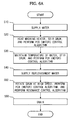
- FIG. 5 is a flow chart illustrating a tub washing process of the washing machine according to the embodiment of the present invention.
- V W ⁇ 1 V T - V D / 2 ⁇ 3 ⁇ L
- V W1 the volume of the supplied water
- V T the volume inside the water tub
- V D the volume inside the drum
- the supplied water is heated to a predetermined sterilization reference temperature sufficient to sterilize microorganisms (for example, 70°C) by the washing heater, and, at the same time, the stirring of the drum is performed to accelerate the heating of the water (S2).
- a predetermined sterilization reference temperature sufficient to sterilize microorganisms (for example, 70°C) by the washing heater, and, at the same time, the stirring of the drum is performed to accelerate the heating of the water (S2).
- the stirring speed of the drum is a speed at which the vapor of the water supplied according to Equation 1 can reach the top of the water tub.
- replenishment water is supplied into the water tub to rinse out the sterilized microorganisms and organisms.
- the volume of the replenishment water is decided by the following equation.
- V W2 the volume of the replenishment water.
- a drainage operation is performed (S8).
- the sterilization reference temperature or the temperature maintenance time may be changed by an algorithm set in the controller 31 at the time of the manufacture.
- the supplied water is heated to a predetermined sterilization reference temperature sufficient to sterilize microorganisms (for example, 70 ⁇ ) by the washing heater.
- a predetermined sterilization reference temperature sufficient to sterilize microorganisms (for example, 70 ⁇ ) by the washing heater.
- the stirring of the drum is performed to accelerate the heating of the water, and a PCB (motor) control procedure, which will be described below with reference to FIGS. 6B and 6C , is performed (S20).
- the washing heater 16 is controlled to be on/off to maintain the temperature of the water, and the drum 12 is continuously stirred to sterilize the microorganisms in the washing machine.
- replenishment water is supplied into the water tub 11 to rinse out the sterilized microorganisms and organisms.
- the volume of the replenishment water is controlled by Equation 3. That is, water sufficient to wet the entire water tub 11 by the rotation of the drum is replenished into the water tub 11 (S40).
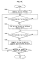
- FIG. 6B is a flow chart illustrating a PCB (motor) control procedure according to an embodiment of the present invention.
- the controller 31 confirms the temperature of the PCB (or motor) to control the driving of the PCB (the speed and on/off intervals of the motor). That is, a temperature sensor (not shown) is attached to the motor 15 or a predetermined part (for example, intelligent power module (IPM)) of the PCB, which is an internal component of the controller 31 to control the washing machine, and the temperature information of the PCB (or motor) is transmitted from the temperature sensor to the controller 31 in real time (S110).
- IPM intelligent power module
- the controller 31 determines whether the temperature change of the PCB (or motor) is equal to or greater than a reference temperature.
- the reference temperature may be arbitrarily set. When the reference temperature is set to be 3 degrees at the time of manufacturing the washing machine, the controller 31 confirms whether the temperature change of the PCB is greater by 3 degrees or more (for example, 38 degrees or more) than the initial temperature when the temperature of the PCB is initially measured (for example, 25 degrees). However, the initial temperature of the PCB is renewed every cycle. On the other hand, when it is determined that the temperature change of the PCB (or motor) is less (for example 25 to 28 degrees) than the initial temperature, the procedure is fed back to operation S110 (S120).
- the controller 31 controls the driving of the PCB to be stopped or the driving force of the PCB to be reduced to stop the driving of the motor 15 or reduce the rotation speed of the motor 15. This is to control the driving force of the motor to prevent the dropping of the safety of the PCB due to the continuous increase in temperature of the PGB (S130).
- the controller 31 confirms the temperature of the PCB (or motor), and confirms whether the temperature change of the PCB (or motor) is equal to or greater than the reference temperature. For example, when the temperature measured immediately after stopping the driving of the motor 15 or reducing the rotation speed of the motor 15 at operation S130 is 28 degrees, the controller 31 confirms whether this temperature drops to be equal to or less than the reference temperature. That is, when the reference temperature is 2 degrees, it is determined whether the temperature of the PCM becomes 26 degrees.
- the initial temperature measured at peration S130 is renewed every cycle (S140 and S150).
- the PCB is driven to commence the driving of the motor 15, or the driving force of the PCB is increased to increase the rotation speed of the motor 15 (S160).
- the controller 31 determines whether the processes of the respective operations have been completed. That is, it is determined at operation S20 whether the temperature of the wash water has reached the sterilization reference temperature (for example, 70 degrees), and it is determined at operations S30 and S50 whether operation times set for the respective operations have elapsed.
- the controller 31 stops the PCB (motor) control procedure, and subsequent operations of the respective operations S20, S30, and S50 are performed.
- the procedure is fed back to operation S110 (S170).
- the controller 31 controls the motor 15 to be driven.
- the driving of the motor 15 may be maintained, or the rotation speed of the motor 15 may be changed to be a speed controlled at the respective operations (S200).
- the controller 31 confirms whether a predetermined time has elapsed.
- the controller 31 controls the driving of the motor 15 to be stopped or the rotation speed of the motor 15 to be reduced. This is an operation performed to prevent the continuous increase in temperature of the motor 15 or the PCB to drive the motor 15 (S210 and S220).
- the controller 31 confirms whether a predetermined time has elapsed.
- the controller 31 controls the driving of the motor 15 to be commenced or the rotation speed of the motor 15 to be increased (S230 and S240).
- the controller 31 compares a growth gradient of the vibration signal transmitted by the vibration sensor 30 with a predetermined value a, and determines whether the vibration signal has entered a resonance band.
- the controller 31 has determined that the vibration signal has entered the resonance band, the RPM of the drum 12 are increased to be RPM deviating from the resonance band (the excessive vibration section) (S320 and S330).
Landscapes
- Engineering & Computer Science (AREA)
- Textile Engineering (AREA)
- Control Of Washing Machine And Dryer (AREA)
Claims (14)
- Verfahren zum Steuern einer Waschmaschine, das umfasst:Zuführen von Wasser zu einem Wasserbehälter (11) beim Reinigen des Behälters;Erhitzen des zugeführten Wassers durch die Waschmaschine;Drehen einer Trommel (12) durch die Waschmaschine mit einer Geschwindigkeit, bei der das zugeführte Wasser gleichmäßig an die Oberseite des Wasserbehälters (11) gelangt, um den Wasserbehälter (11) und die Trommel (12) zu reinigen,dadurch gekennzeichnet, dassein Volumen des zugeführten Wassers durch die Waschmaschine mittels der folgenden Gleichung bestimmt wird:

wobei VW1 = das Volumen des zugeführten Wassers, VT = ein Volumen im Inneren des Wasserbehälters (11), und VD = ein Volumen im Inneren der Trommel (12). - Steuerverfahren nach Anspruch 1, wobei das Drehen umfasst, dass eine Drehgeschwindigkeit der Trommel (12) umgekehrt proportional zu einem Volumen des zugeführten Wassers bestimmt wird oder die Drehgeschwindigkeit der Trommel (12) mittels der folgenden Gleichung bestimmt wird:

wobei RPM = Umdrehungen pro Minute der Trommel (12), VT = ein Volumen im Inneren des Wasserbehälters (11), und VD = ein Volumen im Inneren der Trommel (12). - Steuerverfahren nach Anspruch 1, das des Weiteren umfasst:Nachfüllen eines vorgegebenen Volumens an Nachfüllwasser in den Wasserbehälter (11) nach Reinigen des Wasserbehälters (11) und der Trommel (12); undDrehen der Trommel mit einer Geschwindigkeit, bei der das Nachfüllwasser gleichmäßig an die Oberseite des Wasserbehälters (11) gelangt, um den Wasserbehälter (11) und die Trommel (12) zu spülen.
- Steuerverfahren nach Anspruch 3, das des Weiteren umfasst, dass das Volumen des Nachfüllwassers mittels der folgenden Gleichung bestimmt wird:

wobei VW2 = das Volumen des Nachfüllwassers, VW1 = ein Volumen des zugeführten Wassers, VT = ein Volumen im Inneren des Wasserbehälters (11), und VD = ein Volumen im Inneren der Trommel (12). - Steuerverfahren nach Anspruch 3, das des Weiteren umfasst, dass die Drehgeschwindigkeit der Trommel (12) zum Spülen des Wasserbehälters (11) und der Trommel (12) umgekehrt proportional zu dem Volumen des bei dem Nachfüllvorgang zugeführten Wassers bestimmt wird oder die Drehgeschwindigkeit der Trommel (12) zum Spülen des Wasserbehälters (11) und der Trommel (12) mittels der folgenden Gleichung bestimmt wird:

wobei RPM = Umdrehungen pro Minute der Trommel (12), VT = ein Volumen im Inneren des Wasserbehälters (11), und VD = ein Volumen im Inneren der Trommel (12). - Steuerverfahren nach einem der vorangehenden Ansprüche, das des Weiteren umfasst:Bestimmen eines Temperaturänderungsmaßes einer in der Waschmaschine angebrachten Einheit durch die Waschmaschine beim Reinigen des Behälters; undSteuern eines Drehzustandes der Trommel (12) durch die Waschmaschine entsprechend dem Temperaturänderungsmaß, um Überhitzen der Einheit zu verhindern.
- Steuerverfahren nach Anspruch 6, wobei die Einheit einen Motor (15) oder eine Leiterplatte umfasst.
- Steuerverfahren nach Anspruch 7, wobei das Steuern des Drehzustandes der Trommel (12) durchgeführt wird, um eine Drehgeschwindigkeit oder einen An-/Aus-Zyklus des Motors (15) zum Drehen der Trommel (12) zu steuern.
- Steuerverfahren nach Anspruch 7, wobei
das Reinigen des Behälters über eine Vielzahl von Vorgängen durchgeführt wird, und
der Drehzustand der Trommel (12) in Kombination mit Steuerung einer Drehgeschwindigkeit des Motors (15) zum Drehen der Trommel (12) oder zum Steuern des An-/Aus-Zustandes des Motors (15) bei den Vorgängen gesteuert wird. - Steuerverfahren nach Anspruch 9, wobei:die Vorgänge einen Heizvorgang und einen Haltevorgang sowie einen Spülvorgang einschließen, der Drehzustand der Trommel (12) so gesteuert wird, dass der An-/Aus-Zustand des Motors (15) bei dem Heizvorgang und dem Haltevorgang gesteuert wird, und der Drehzustand der Trommel (12) so gesteuert wird, dass die Geschwindigkeit des Motors (15) bei dem Spülvorgang gesteuert wird.
- Steuerverfahren nach einem der Ansprüche 1-5, das des Weiteren umfasst:Bewegen oder Drehen einer Trommel (12) beim Reinigen der Trommel durch die Waschmaschine; undSteuern einer Drehgeschwindigkeit oder eines An-/Aus-Zustandes eines Motors (15) durch die Waschmaschine zum Bewegen oder Drehen der Trommel (12) in vorgegebenen Zeitintervallen, um einen Drehzustand der Trommel (12) zu steuern.
- Steuerverfahren nach Anspruch 11, wobei:das Reinigen der Trommel über eine Vielzahl von Vorgängen durchgeführt wird, undSteuern der Drehgeschwindigkeit des Motors (15) oder Steuern des An-/Aus-Zustandes des Motors (15) bei den Vorgängen in Kombination eingesetzt wird.
- Steuerverfahren nach Anspruch 12, wobei:die Vorgänge einen Heizvorgang und einen Haltevorgang sowie einen Spülvorgang einschließen, der Drehzustand der Trommel (12) gesteuert wird, um den An-/Aus-Zustand des Motors (15) bei dem Heizvorgang und dem Haltevorgang zu steuern, und der Drehzustand der Trommel (12) gesteuert wird, um die Geschwindigkeit des Motors (15) bei dem Spülvorgang zu steuern.
- Steuerverfahren nach Anspruch 13, wobei An-/Aus-Zyklen des Motors (15) so festgelegt werden, dass sie bei den jeweiligen Vorgängen unterschiedlich sind.
Applications Claiming Priority (2)
| Application Number | Priority Date | Filing Date | Title |
|---|---|---|---|
| KR1020080065149A KR20100004799A (ko) | 2008-07-04 | 2008-07-04 | 세탁기의 제어방법 |
| KR1020080102775A KR20100043664A (ko) | 2008-10-20 | 2008-10-20 | 세탁기의 제어방법 |
Publications (3)
| Publication Number | Publication Date |
|---|---|
| EP2141274A2 EP2141274A2 (de) | 2010-01-06 |
| EP2141274A3 EP2141274A3 (de) | 2010-02-24 |
| EP2141274B1 true EP2141274B1 (de) | 2012-12-19 |
Family
ID=41056923
Family Applications (1)
| Application Number | Title | Priority Date | Filing Date |
|---|---|---|---|
| EP09163432A Not-in-force EP2141274B1 (de) | 2008-07-04 | 2009-06-23 | Verfahren für das Waschen des Bottichs einer Waschmaschine |
Country Status (2)
| Country | Link |
|---|---|
| US (1) | US8020231B2 (de) |
| EP (1) | EP2141274B1 (de) |
Families Citing this family (8)
| Publication number | Priority date | Publication date | Assignee | Title |
|---|---|---|---|---|
| KR20110116794A (ko) * | 2010-04-20 | 2011-10-26 | 삼성전자주식회사 | 세탁기 및 그 제어방법 |
| KR20150075626A (ko) * | 2013-12-26 | 2015-07-06 | 동부대우전자 주식회사 | 세탁기의 진동 저감 장치 및 방법 |
| KR102747142B1 (ko) * | 2017-01-18 | 2024-12-27 | 삼성전자주식회사 | 건조기 및 상기 건조기의 제어 방법 |
| CN108950980B (zh) * | 2017-05-23 | 2022-06-28 | 合肥海尔滚筒洗衣机有限公司 | 洗衣机及其蒸汽洗方法 |
| TW201945612A (zh) * | 2018-04-16 | 2019-12-01 | 日商松下知識產權經營股份有限公司 | 洗衣機 |
| TW202003957A (zh) * | 2018-05-29 | 2020-01-16 | 日商松下知識產權經營股份有限公司 | 洗衣機 |
| CN111155269B (zh) * | 2019-12-30 | 2023-07-14 | 合肥美的洗衣机有限公司 | 衣物处理装置及其控制方法、控制装置 |
| JP7199732B2 (ja) * | 2020-07-31 | 2023-01-06 | アイリスオーヤマ株式会社 | 洗濯機 |
Family Cites Families (20)
| Publication number | Priority date | Publication date | Assignee | Title |
|---|---|---|---|---|
| US3702069A (en) * | 1971-07-01 | 1972-11-07 | Gen Motors Corp | Apparatus for sanitizing a domestic clothes washer |
| US3770376A (en) * | 1971-07-01 | 1973-11-06 | Gen Motors Corp | Method for sanitizing a domestic clothes washer |
| JPS5985688A (ja) * | 1982-11-08 | 1984-05-17 | 株式会社日立製作所 | コインスイツチ付全自動洗濯機 |
| JPH02161997A (ja) * | 1988-12-15 | 1990-06-21 | Matsushita Electric Ind Co Ltd | 全自動洗濯機 |
| DE19751028C2 (de) * | 1997-11-19 | 2001-12-06 | Miele & Cie | Verfahren zur Durchführung eines Hygieneprogramms |
| JPH11244581A (ja) * | 1998-03-05 | 1999-09-14 | Matsushita Electric Ind Co Ltd | 洗濯機 |
| KR20010093969A (ko) | 2000-04-03 | 2001-10-31 | 구자홍 | 전자동 세탁기의 세탁조 세정방법 |
| JP3862549B2 (ja) * | 2001-11-08 | 2006-12-27 | シャープ株式会社 | 乾燥洗濯機 |
| KR100662300B1 (ko) | 2003-03-14 | 2007-01-02 | 엘지전자 주식회사 | 세탁기 조세정 방법 |
| KR100707346B1 (ko) * | 2004-07-07 | 2007-04-13 | 삼성전자주식회사 | 세탁기 및 제어방법 |
| JP2006167243A (ja) * | 2004-12-17 | 2006-06-29 | Choji Yamazaki | 二重槽式洗濯機の殺菌装置 |
| KR20060082689A (ko) | 2005-01-13 | 2006-07-19 | 삼성전자주식회사 | 세탁기 및 세탁조 세척방법 |
| KR100624719B1 (ko) * | 2005-01-25 | 2006-09-20 | 엘지전자 주식회사 | 건조 겸용 세탁기의 통 살균 제어 방법 |
| KR100712847B1 (ko) | 2005-01-25 | 2007-05-02 | 엘지전자 주식회사 | 세탁기의 통 살균 제어 방법 |
| EP1851374B1 (de) | 2005-02-25 | 2014-11-05 | LG Electronics Inc. | Verfahren zum waschen eines bottichs oder einer trommel in einer waschmaschine |
| KR100698304B1 (ko) | 2005-03-22 | 2007-03-23 | 엘지전자 주식회사 | 드럼 세탁기의 세척조 세정 방법 |
| DE102006030013A1 (de) * | 2005-06-30 | 2007-01-18 | Lg Electronics Inc. | Verfahren zum Steuern des Waschablaufs einer Waschmaschine |
| JP4476274B2 (ja) * | 2006-02-14 | 2010-06-09 | シャープ株式会社 | 洗濯機 |
| DE102006024505B3 (de) | 2006-05-23 | 2007-05-31 | Miele & Cie. Kg | Verfahren zum Betreiben einer Waschmaschine und Waschmaschine |
| US20080095660A1 (en) * | 2006-10-19 | 2008-04-24 | Nyik Siong Wong | Method for treating biofilm in an appliance |
-
2009
- 2009-03-13 US US12/403,450 patent/US8020231B2/en active Active
- 2009-06-23 EP EP09163432A patent/EP2141274B1/de not_active Not-in-force
Also Published As
| Publication number | Publication date |
|---|---|
| US8020231B2 (en) | 2011-09-20 |
| EP2141274A3 (de) | 2010-02-24 |
| US20100000574A1 (en) | 2010-01-07 |
| EP2141274A2 (de) | 2010-01-06 |
Similar Documents
| Publication | Publication Date | Title |
|---|---|---|
| EP2141274B1 (de) | Verfahren für das Waschen des Bottichs einer Waschmaschine | |
| EP1977032B1 (de) | Waschmaschine und waschverfahren mithilfe von dampf dafür | |
| JP4705101B2 (ja) | 洗濯機及びその製造方法 | |
| US9605367B2 (en) | Method of controlling washing machine | |
| US9587345B2 (en) | Drum-type washer and tub cleaning method of the same | |
| US8387189B2 (en) | Method for washing of washer | |
| RU2303667C2 (ru) | Стиральная машина и способ очистки бака для стирки (варианты) | |
| EP2034079B1 (de) | Waschmaschine und Steuerungsverfahren | |
| EP2236658B1 (de) | Waschmaschine und Steuerungsverfahren dafür | |
| EP0957194B1 (de) | Verfahren zum Waschen von Wäsche | |
| US20100192310A1 (en) | Method for controlling the generation of suds in a washing machine and a washing machine suitable therefor | |
| WO2003054277A1 (en) | Washing machine | |
| EP2372007B1 (de) | Waschmaschine und dampfwaschverfahren dafür | |
| KR20080076652A (ko) | 세탁기 및 그 제어방법 | |
| US20100235999A1 (en) | Method for treatment of laundry and washing machine suitable for this purpose | |
| KR20100082666A (ko) | 세탁수 온도 제어방법 | |
| KR100692619B1 (ko) | 세탁기의 세탁조 관리방법 | |
| KR101552831B1 (ko) | 세탁기의 제어방법 | |
| KR20100043664A (ko) | 세탁기의 제어방법 | |
| KR20100004799A (ko) | 세탁기의 제어방법 | |
| JP7823824B2 (ja) | ランドリー機器 | |
| KR100707346B1 (ko) | 세탁기 및 제어방법 | |
| KR100689935B1 (ko) | 드럼식 세탁기 | |
| KR100211239B1 (ko) | 세탁기의 삶는 세탁방법 | |
| KR19990012117A (ko) | 세탁기의 구동제어방법 |
Legal Events
| Date | Code | Title | Description |
|---|---|---|---|
| PUAI | Public reference made under article 153(3) epc to a published international application that has entered the european phase |
Free format text: ORIGINAL CODE: 0009012 |
|
| AK | Designated contracting states |
Kind code of ref document: A2 Designated state(s): AT BE BG CH CY CZ DE DK EE ES FI FR GB GR HR HU IE IS IT LI LT LU LV MC MK MT NL NO PL PT RO SE SI SK TR |
|
| PUAL | Search report despatched |
Free format text: ORIGINAL CODE: 0009013 |
|
| AK | Designated contracting states |
Kind code of ref document: A3 Designated state(s): AT BE BG CH CY CZ DE DK EE ES FI FR GB GR HR HU IE IS IT LI LT LU LV MC MK MT NL NO PL PT RO SE SI SK TR |
|
| 17P | Request for examination filed |
Effective date: 20100804 |
|
| 17Q | First examination report despatched |
Effective date: 20100906 |
|
| GRAP | Despatch of communication of intention to grant a patent |
Free format text: ORIGINAL CODE: EPIDOSNIGR1 |
|
| RAP1 | Party data changed (applicant data changed or rights of an application transferred) |
Owner name: SAMSUNG ELECTRONICS CO., LTD. |
|
| GRAS | Grant fee paid |
Free format text: ORIGINAL CODE: EPIDOSNIGR3 |
|
| GRAA | (expected) grant |
Free format text: ORIGINAL CODE: 0009210 |
|
| AK | Designated contracting states |
Kind code of ref document: B1 Designated state(s): AT BE BG CH CY CZ DE DK EE ES FI FR GB GR HR HU IE IS IT LI LT LU LV MC MK MT NL NO PL PT RO SE SI SK TR |
|
| REG | Reference to a national code |
Ref country code: GB Ref legal event code: FG4D |
|
| REG | Reference to a national code |
Ref country code: CH Ref legal event code: EP |
|
| REG | Reference to a national code |
Ref country code: AT Ref legal event code: REF Ref document number: 589492 Country of ref document: AT Kind code of ref document: T Effective date: 20130115 |
|
| REG | Reference to a national code |
Ref country code: DE Ref legal event code: R096 Ref document number: 602009011997 Country of ref document: DE Effective date: 20130221 |
|
| PG25 | Lapsed in a contracting state [announced via postgrant information from national office to epo] |
Ref country code: SE Free format text: LAPSE BECAUSE OF FAILURE TO SUBMIT A TRANSLATION OF THE DESCRIPTION OR TO PAY THE FEE WITHIN THE PRESCRIBED TIME-LIMIT Effective date: 20121219 Ref country code: FI Free format text: LAPSE BECAUSE OF FAILURE TO SUBMIT A TRANSLATION OF THE DESCRIPTION OR TO PAY THE FEE WITHIN THE PRESCRIBED TIME-LIMIT Effective date: 20121219 Ref country code: NO Free format text: LAPSE BECAUSE OF FAILURE TO SUBMIT A TRANSLATION OF THE DESCRIPTION OR TO PAY THE FEE WITHIN THE PRESCRIBED TIME-LIMIT Effective date: 20130319 Ref country code: LT Free format text: LAPSE BECAUSE OF FAILURE TO SUBMIT A TRANSLATION OF THE DESCRIPTION OR TO PAY THE FEE WITHIN THE PRESCRIBED TIME-LIMIT Effective date: 20121219 Ref country code: HR Free format text: LAPSE BECAUSE OF FAILURE TO SUBMIT A TRANSLATION OF THE DESCRIPTION OR TO PAY THE FEE WITHIN THE PRESCRIBED TIME-LIMIT Effective date: 20121219 Ref country code: ES Free format text: LAPSE BECAUSE OF FAILURE TO SUBMIT A TRANSLATION OF THE DESCRIPTION OR TO PAY THE FEE WITHIN THE PRESCRIBED TIME-LIMIT Effective date: 20130330 |
|
| REG | Reference to a national code |
Ref country code: NL Ref legal event code: VDEP Effective date: 20121219 Ref country code: AT Ref legal event code: MK05 Ref document number: 589492 Country of ref document: AT Kind code of ref document: T Effective date: 20121219 |
|
| REG | Reference to a national code |
Ref country code: LT Ref legal event code: MG4D |
|
| PG25 | Lapsed in a contracting state [announced via postgrant information from national office to epo] |
Ref country code: GR Free format text: LAPSE BECAUSE OF FAILURE TO SUBMIT A TRANSLATION OF THE DESCRIPTION OR TO PAY THE FEE WITHIN THE PRESCRIBED TIME-LIMIT Effective date: 20130320 Ref country code: SI Free format text: LAPSE BECAUSE OF FAILURE TO SUBMIT A TRANSLATION OF THE DESCRIPTION OR TO PAY THE FEE WITHIN THE PRESCRIBED TIME-LIMIT Effective date: 20121219 Ref country code: LV Free format text: LAPSE BECAUSE OF FAILURE TO SUBMIT A TRANSLATION OF THE DESCRIPTION OR TO PAY THE FEE WITHIN THE PRESCRIBED TIME-LIMIT Effective date: 20121219 |
|
| PG25 | Lapsed in a contracting state [announced via postgrant information from national office to epo] |
Ref country code: BE Free format text: LAPSE BECAUSE OF FAILURE TO SUBMIT A TRANSLATION OF THE DESCRIPTION OR TO PAY THE FEE WITHIN THE PRESCRIBED TIME-LIMIT Effective date: 20121219 Ref country code: BG Free format text: LAPSE BECAUSE OF FAILURE TO SUBMIT A TRANSLATION OF THE DESCRIPTION OR TO PAY THE FEE WITHIN THE PRESCRIBED TIME-LIMIT Effective date: 20130319 Ref country code: EE Free format text: LAPSE BECAUSE OF FAILURE TO SUBMIT A TRANSLATION OF THE DESCRIPTION OR TO PAY THE FEE WITHIN THE PRESCRIBED TIME-LIMIT Effective date: 20121219 Ref country code: SK Free format text: LAPSE BECAUSE OF FAILURE TO SUBMIT A TRANSLATION OF THE DESCRIPTION OR TO PAY THE FEE WITHIN THE PRESCRIBED TIME-LIMIT Effective date: 20121219 Ref country code: CZ Free format text: LAPSE BECAUSE OF FAILURE TO SUBMIT A TRANSLATION OF THE DESCRIPTION OR TO PAY THE FEE WITHIN THE PRESCRIBED TIME-LIMIT Effective date: 20121219 Ref country code: IS Free format text: LAPSE BECAUSE OF FAILURE TO SUBMIT A TRANSLATION OF THE DESCRIPTION OR TO PAY THE FEE WITHIN THE PRESCRIBED TIME-LIMIT Effective date: 20130419 Ref country code: AT Free format text: LAPSE BECAUSE OF FAILURE TO SUBMIT A TRANSLATION OF THE DESCRIPTION OR TO PAY THE FEE WITHIN THE PRESCRIBED TIME-LIMIT Effective date: 20121219 |
|
| PG25 | Lapsed in a contracting state [announced via postgrant information from national office to epo] |
Ref country code: PT Free format text: LAPSE BECAUSE OF FAILURE TO SUBMIT A TRANSLATION OF THE DESCRIPTION OR TO PAY THE FEE WITHIN THE PRESCRIBED TIME-LIMIT Effective date: 20130419 Ref country code: RO Free format text: LAPSE BECAUSE OF FAILURE TO SUBMIT A TRANSLATION OF THE DESCRIPTION OR TO PAY THE FEE WITHIN THE PRESCRIBED TIME-LIMIT Effective date: 20121219 Ref country code: PL Free format text: LAPSE BECAUSE OF FAILURE TO SUBMIT A TRANSLATION OF THE DESCRIPTION OR TO PAY THE FEE WITHIN THE PRESCRIBED TIME-LIMIT Effective date: 20121219 Ref country code: NL Free format text: LAPSE BECAUSE OF FAILURE TO SUBMIT A TRANSLATION OF THE DESCRIPTION OR TO PAY THE FEE WITHIN THE PRESCRIBED TIME-LIMIT Effective date: 20121219 |
|
| PLBE | No opposition filed within time limit |
Free format text: ORIGINAL CODE: 0009261 |
|
| STAA | Information on the status of an ep patent application or granted ep patent |
Free format text: STATUS: NO OPPOSITION FILED WITHIN TIME LIMIT |
|
| PG25 | Lapsed in a contracting state [announced via postgrant information from national office to epo] |
Ref country code: DK Free format text: LAPSE BECAUSE OF FAILURE TO SUBMIT A TRANSLATION OF THE DESCRIPTION OR TO PAY THE FEE WITHIN THE PRESCRIBED TIME-LIMIT Effective date: 20121219 |
|
| 26N | No opposition filed |
Effective date: 20130920 |
|
| PG25 | Lapsed in a contracting state [announced via postgrant information from national office to epo] |
Ref country code: CY Free format text: LAPSE BECAUSE OF FAILURE TO SUBMIT A TRANSLATION OF THE DESCRIPTION OR TO PAY THE FEE WITHIN THE PRESCRIBED TIME-LIMIT Effective date: 20121219 |
|
| PG25 | Lapsed in a contracting state [announced via postgrant information from national office to epo] |
Ref country code: IT Free format text: LAPSE BECAUSE OF FAILURE TO SUBMIT A TRANSLATION OF THE DESCRIPTION OR TO PAY THE FEE WITHIN THE PRESCRIBED TIME-LIMIT Effective date: 20121219 |
|
| REG | Reference to a national code |
Ref country code: DE Ref legal event code: R097 Ref document number: 602009011997 Country of ref document: DE Effective date: 20130920 |
|
| PG25 | Lapsed in a contracting state [announced via postgrant information from national office to epo] |
Ref country code: MC Free format text: LAPSE BECAUSE OF FAILURE TO SUBMIT A TRANSLATION OF THE DESCRIPTION OR TO PAY THE FEE WITHIN THE PRESCRIBED TIME-LIMIT Effective date: 20121219 |
|
| REG | Reference to a national code |
Ref country code: CH Ref legal event code: PL |
|
| REG | Reference to a national code |
Ref country code: IE Ref legal event code: MM4A |
|
| PG25 | Lapsed in a contracting state [announced via postgrant information from national office to epo] |
Ref country code: LI Free format text: LAPSE BECAUSE OF NON-PAYMENT OF DUE FEES Effective date: 20130630 Ref country code: IE Free format text: LAPSE BECAUSE OF NON-PAYMENT OF DUE FEES Effective date: 20130623 Ref country code: CH Free format text: LAPSE BECAUSE OF NON-PAYMENT OF DUE FEES Effective date: 20130630 |
|
| PG25 | Lapsed in a contracting state [announced via postgrant information from national office to epo] |
Ref country code: MT Free format text: LAPSE BECAUSE OF FAILURE TO SUBMIT A TRANSLATION OF THE DESCRIPTION OR TO PAY THE FEE WITHIN THE PRESCRIBED TIME-LIMIT Effective date: 20121219 |
|
| PG25 | Lapsed in a contracting state [announced via postgrant information from national office to epo] |
Ref country code: TR Free format text: LAPSE BECAUSE OF FAILURE TO SUBMIT A TRANSLATION OF THE DESCRIPTION OR TO PAY THE FEE WITHIN THE PRESCRIBED TIME-LIMIT Effective date: 20121219 |
|
| PG25 | Lapsed in a contracting state [announced via postgrant information from national office to epo] |
Ref country code: LU Free format text: LAPSE BECAUSE OF NON-PAYMENT OF DUE FEES Effective date: 20130623 Ref country code: MK Free format text: LAPSE BECAUSE OF FAILURE TO SUBMIT A TRANSLATION OF THE DESCRIPTION OR TO PAY THE FEE WITHIN THE PRESCRIBED TIME-LIMIT Effective date: 20121219 Ref country code: HU Free format text: LAPSE BECAUSE OF FAILURE TO SUBMIT A TRANSLATION OF THE DESCRIPTION OR TO PAY THE FEE WITHIN THE PRESCRIBED TIME-LIMIT; INVALID AB INITIO Effective date: 20090623 |
|
| REG | Reference to a national code |
Ref country code: FR Ref legal event code: PLFP Year of fee payment: 8 |
|
| REG | Reference to a national code |
Ref country code: FR Ref legal event code: PLFP Year of fee payment: 9 |
|
| REG | Reference to a national code |
Ref country code: FR Ref legal event code: PLFP Year of fee payment: 10 |
|
| PGFP | Annual fee paid to national office [announced via postgrant information from national office to epo] |
Ref country code: FR Payment date: 20210524 Year of fee payment: 13 |
|
| PGFP | Annual fee paid to national office [announced via postgrant information from national office to epo] |
Ref country code: GB Payment date: 20220520 Year of fee payment: 14 |
|
| PG25 | Lapsed in a contracting state [announced via postgrant information from national office to epo] |
Ref country code: FR Free format text: LAPSE BECAUSE OF NON-PAYMENT OF DUE FEES Effective date: 20220630 |
|
| PGFP | Annual fee paid to national office [announced via postgrant information from national office to epo] |
Ref country code: DE Payment date: 20230522 Year of fee payment: 15 |
|
| GBPC | Gb: european patent ceased through non-payment of renewal fee |
Effective date: 20230623 |
|
| PG25 | Lapsed in a contracting state [announced via postgrant information from national office to epo] |
Ref country code: GB Free format text: LAPSE BECAUSE OF NON-PAYMENT OF DUE FEES Effective date: 20230623 |
|
| REG | Reference to a national code |
Ref country code: DE Ref legal event code: R119 Ref document number: 602009011997 Country of ref document: DE |
|
| PG25 | Lapsed in a contracting state [announced via postgrant information from national office to epo] |
Ref country code: DE Free format text: LAPSE BECAUSE OF NON-PAYMENT OF DUE FEES Effective date: 20250101 |