EP2141338A2 - Regeleinheit - Google Patents
Regeleinheit Download PDFInfo
- Publication number
- EP2141338A2 EP2141338A2 EP09251662A EP09251662A EP2141338A2 EP 2141338 A2 EP2141338 A2 EP 2141338A2 EP 09251662 A EP09251662 A EP 09251662A EP 09251662 A EP09251662 A EP 09251662A EP 2141338 A2 EP2141338 A2 EP 2141338A2
- Authority
- EP
- European Patent Office
- Prior art keywords
- fuel
- manifold
- motor
- control
- valve
- Prior art date
- Legal status (The legal status is an assumption and is not a legal conclusion. Google has not performed a legal analysis and makes no representation as to the accuracy of the status listed.)
- Withdrawn
Links
- 239000012530 fluid Substances 0.000 claims abstract description 5
- 239000000446 fuel Substances 0.000 claims description 65
- 230000007246 mechanism Effects 0.000 description 3
- 230000000630 rising effect Effects 0.000 description 3
- 230000004075 alteration Effects 0.000 description 2
- 230000015556 catabolic process Effects 0.000 description 2
- 238000006731 degradation reaction Methods 0.000 description 2
- 238000010586 diagram Methods 0.000 description 2
- 230000000694 effects Effects 0.000 description 2
- 238000012986 modification Methods 0.000 description 2
- 230000004048 modification Effects 0.000 description 2
- 238000007789 sealing Methods 0.000 description 2
- RZVHIXYEVGDQDX-UHFFFAOYSA-N 9,10-anthraquinone Chemical compound C1=CC=C2C(=O)C3=CC=CC=C3C(=O)C2=C1 RZVHIXYEVGDQDX-UHFFFAOYSA-N 0.000 description 1
- 238000006243 chemical reaction Methods 0.000 description 1
- 238000002485 combustion reaction Methods 0.000 description 1
- 238000001816 cooling Methods 0.000 description 1
- 230000035945 sensitivity Effects 0.000 description 1
Images
Classifications
-
- F—MECHANICAL ENGINEERING; LIGHTING; HEATING; WEAPONS; BLASTING
- F02—COMBUSTION ENGINES; HOT-GAS OR COMBUSTION-PRODUCT ENGINE PLANTS
- F02C—GAS-TURBINE PLANTS; AIR INTAKES FOR JET-PROPULSION PLANTS; CONTROLLING FUEL SUPPLY IN AIR-BREATHING JET-PROPULSION PLANTS
- F02C7/00—Features, components parts, details or accessories, not provided for in, or of interest apart form groups F02C1/00 - F02C6/00; Air intakes for jet-propulsion plants
- F02C7/22—Fuel supply systems
- F02C7/232—Fuel valves; Draining valves or systems
-
- F—MECHANICAL ENGINEERING; LIGHTING; HEATING; WEAPONS; BLASTING
- F02—COMBUSTION ENGINES; HOT-GAS OR COMBUSTION-PRODUCT ENGINE PLANTS
- F02C—GAS-TURBINE PLANTS; AIR INTAKES FOR JET-PROPULSION PLANTS; CONTROLLING FUEL SUPPLY IN AIR-BREATHING JET-PROPULSION PLANTS
- F02C7/00—Features, components parts, details or accessories, not provided for in, or of interest apart form groups F02C1/00 - F02C6/00; Air intakes for jet-propulsion plants
- F02C7/22—Fuel supply systems
- F02C7/222—Fuel flow conduits, e.g. manifolds
-
- F—MECHANICAL ENGINEERING; LIGHTING; HEATING; WEAPONS; BLASTING
- F02—COMBUSTION ENGINES; HOT-GAS OR COMBUSTION-PRODUCT ENGINE PLANTS
- F02C—GAS-TURBINE PLANTS; AIR INTAKES FOR JET-PROPULSION PLANTS; CONTROLLING FUEL SUPPLY IN AIR-BREATHING JET-PROPULSION PLANTS
- F02C9/00—Controlling gas-turbine plants; Controlling fuel supply in air- breathing jet-propulsion plants
- F02C9/26—Control of fuel supply
Definitions
- control system may form part of a fuel system for use in the supply of fuel to an aircraft engine.
- the invention relates to a fuel system permitting control over the fuel staging system of such an engine.
- US 4036246 describes a fuel system in which a series of linkages are provided to control the operation of the valves.
- the linkages together form a unison ring.
- the linkages are movable by an appropriate actuator.
- the linkages are located externally but, in the arrangement of US 4036246 , they are located within the manifold used to deliver fuel to the valves.
- a control system comprising a manifold, at least one valve device operable to control the delivery of fluid from the manifold, and a drive member located within the manifold and rotatable to control the operation of the at least one valve device.
- the control system may comprise part of a fuel system, for example for an aircraft engine, the manifold comprising a fuel manifold from which fuel is delivered, in use, via the valve devices.
- the invention is also applicable to other control systems.
- the manifold further houses at least part of an input gear arrangement whereby the drive member is rotated.
- An input drive shaft may be provided to transmit rotary motion from a motor to the drive member and/or input gear arrangement.
- the input drive shaft may be located within a fuel supply line whereby fuel is supplied to the manifold, thereby negating the need for fuel/air dynamic seal arrangements.
- the input drive shaft may pass through a seal arrangement into the manifold and/or input gear arrangement.
- the motor may be an electrically driven motor. Alternatively, it may comprise a hydraulic motor driven, for example, using pressurised fuel.
- the manifold preferably houses a series of further drive members, or alternatively one continuous drive member, and gear arrangements arranged to form a drive train preferably in the form of a continuous loop. Each gear arrangement is preferably further arranged to transmit rotary motion to one or more of said valve devices.
- a sensor may be provided to monitor the rotary position of the drive member, the input drive shaft and/or the motor to provide an output signal representative of the operating mode of the valve devices. Additional sensors may be provided to monitor the positions of the valve devices.
- valve devices Preferably there is a continuous flow of fuel through the valve devices at all engine operating conditions, thereby providing a means of maintaining the temperature of the valve devices at an acceptable level.
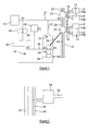
- FIG. 2 is a diagram illustrating a control system in accordance with another embodiment.
- the fuel system illustrated in Figure 1 comprises a hydro-mechanical unit (HMU) 10 arranged to supply fuel through a supply line 12 to a fuel manifold 14.
- the HMU 10 may take a range of forms, for example it may comprise a high pressure fuel pump arranged to supply fuel through a metering valve, the operation of which is controlled to control the rate at which fuel is supplied to the supply line 12.
- a spill valve arrangement may be incorporated into the HMU 10 to allow excess fuel to be returned to inlet side of the high pressure pump. Fuel systems of this general type are well known and so the HMU 10 will not be described in further detail.
- the manifold 14 communicates via a series of staging valve lines 16 with a series of staging valves 18.
- Each staging valve 18 is operable, in this embodiment, to supply fuel through a series of pilot outlet openings and a series of main outlet openings, the staging valves 18 incorporating a control mechanism whereby certain of the outlet openings can be closed such that, for example, fuel can be delivered in a pilot delivery mode only.
- a number of valve designs of this general type are known, so no further description thereof is included herein. However, the design of the valves is such that there is continuous flow of fuel through the valves at all engine operating conditions thus ensuring that the temperature of the valves is maintained at an acceptable level to prevent fuel degradation.
- a series of rotatable drive members 20 in the form of flexible drive shafts.
- one continuous rotatable drive member could be located within the manifold in the form of one continuous flexible drive shaft.
- the drive shaft or shafts are arranged to be rotated, in use, about their longitudinal "axes", and held against significant "radial” movement.
- the flexible drive shafts are of high torsional stiffness and may be of the type described in US 4112708 .
- the drive members 20 are interconnected with one another by means of gear arrangements 22, the drive members 20 and gear arrangements 22, together forming a drive train in the form of a continuous loop extending about the entire manifold 14.
- the gear arrangements 22 transmit rotary motion between the adjacent members 20 and may take a range of forms.
- the gear arrangements 22, as well as transmitting rotary motion between adjacent ones of the drive members 20, are further arranged to drive a series of output shafts 24 for rotation, the output shafts 24 being located within respective ones of the staging valve lines 16.
- the output shafts 24 are connected to the control mechanisms of respective ones of the staging valves 18 and are arranged such that rotation of the drive members 20 which is transmitted through the gear arrangements 22 to the output shafts 24 controls the mode of operation of each of the staging valves 18.
- the fuel system illustrated in Figure 1 further comprises a hydraulic motor 26 arranged to be driven using fuel under pressure.
- An input drive shaft 28 interconnects the motor 26 and an input one of the gear arrangements 22, and it will be appreciated that operation of the motor 26 can thus be used to control the rotary positions of the drive members 20, gear arrangements 22, output drive shafts 24, and hence the operating modes of the staging valves 18.
- the input drive shaft 28 passes directly into one of the gear arrangements 22, through a suitable sealing arrangement provided in the gear arrangement 22 and/or manifold 14.
- the input drive shaft 28 is housed within a fuel line connected to the manifold 14, for example in some arrangements the input drive shaft 28 may extend through part of the supply line 12 and into the manifold 14. This would advantageously negate the need for a suitable fuel/air dynamic sealing arrangement.
- the motor 26 comprises a hydraulic gear motor, the operation of which is controlled by a servo-valve and torque motor arrangement 38 hereinafter referred to as the control valve 38.
- the motor 26 is connected between first and second outputs of the control valve 38 via respective fuel lines 30 and 36. These fuel lines 30, 36 are then connected via a fixed orifice arrangement 34 to the supply line 12, via a line 32, which is held at a pressure P1 equal to or substantially equal to the fuel pressure at which fuel is supplied by the HMU 10.
- a servo-pump 40 is arranged to pressurise a quantity of fuel from the line 12 to an increased pressure P2, fuel from the servo-pump 40 being supplied to the control valve 38. This increased pressure is required to provide satisfactory control of the motor 26 via the control valve 38. As well as controlling the operation of the motor 26, the control valve 38 and fixed orifice arrangement 34 ensure that adequate flow of fuel is maintained through the fuel lines 30, 36 at all engine operating conditions. This ensures that the temperature of the fuel system, and in particular that part of the fuel system which is located in the high temperature core zone of the engine, is maintained at an acceptable level, thus minimising the risk of fuel degradation.
- a pressure limiting valve 42 is connected between the output of the servo-pump 40 and the line 12 to prevent the pressure P2 rising to an unacceptably high pressure.
- the respective pressures P3 and P4 in the fuel lines 30 and 36 are adjusted to control the operation of the motor 26.
- the control valve 38 operated such that P3 is greater than P4 the motor 26 rotates in a first direction.
- Such rotation of the motor 26 is transmitted to the staging valves 18 as described hereinbefore and is used to drive the staging valves 18 from, for example, a pilot operating mode to a main operating mode.
- P3 is less than P4 resulting in rotation of the motor 26 in a second, opposite direction.
- Such rotation is transmitted to the staging valves 18 resulting in the staging valves 18 returning from, for example, the main delivery mode to the pilot delivery mode.
- continued operation of the servo-pump 40 may result in the pressure P2 rising to the point at which the pressure limiting valve 42 opens to prevent the pressure P2 rising to an excessively high level.
- a sensor 44 is provided to monitor the operation of the motor 26. By sensing the position of the motor 26 it will be appreciated that a signal representative of the position or operating mode of the staging valves 18 can be produced. This signal is used by an Engine Control Unit (not shown) in conjunction with known engine control loop staged combustion algorithms (ie pilot/mains flow split calculations) to provide a control signal to the control valve 38 that is required in providing the necessary control of the operation of the motor 26, thereby permitting accurate control over the staging valves 18.
- Engine Control Unit not shown
- known engine control loop staged combustion algorithms ie pilot/mains flow split calculations
- the arrangement described hereinbefore is advantageous compared to known arrangements in that the number of fuel lines provided in the high temperature core zone of the engine is reduced, and there is continuous flow of fuel in the remaining lines, thereby avoiding fuel lines containing stagnant fuel in a high temperature environment, and hence negating the need of an additional requirement for fuel cooling.
- the location of the drive members 20 within the manifold 14 and also the input drive shaft 28 extending through part of the supply line 12 and into the manifold 14 avoids the necessity of providing dynamic fuel/air seals in the high temperature core zone of the engine.
- the provision of the drive members 20 and gear arrangements 22 in the form of a continuous loop results in the system being of reduced sensitivity to single point failures in that, for example, continued operation of the staging valves 18 may be achievable despite the failure of, for example, one of the drive members 20.
- the provision of the sensor 44 permits accurate, closed loop control over the operation of the staging valves.
- the control mechanisms of the staging valves 18 may take a range of forms. Where a rotary input is required this may be derived directly from the rotation of the output drive shafts, conveniently via a gearbox. Where a linear input is required, any suitable rotary to linear conversion device may be used, for example a ball screw-type device, to convert the rotary motion of the output drive shaft to the linear motion of the staging valve 18. In either case, down gearing may be achieved at this point.
- the control valve 54 is operable to control the fluid pressure within a line 56 by controlling the connection of the line 56 to the manifolds 50, 52.
- the control valve 54 is mechanically actuated, and a drive input thereof is connected to a rotatable drive member 58 located within, in this case, the high pressure manifold 50 such that rotation of the drive member 58 controls the setting of the control valve 54 and thereby controls the fluid pressure within the line 56.
- a system of this general type may have a wide range of applications. A number of other modifications and alterations are possible without departing from the scope of the invention.
Landscapes
- Engineering & Computer Science (AREA)
- Chemical & Material Sciences (AREA)
- Combustion & Propulsion (AREA)
- Mechanical Engineering (AREA)
- General Engineering & Computer Science (AREA)
- Fuel-Injection Apparatus (AREA)
- Multiple-Way Valves (AREA)
- Electrically Driven Valve-Operating Means (AREA)
Applications Claiming Priority (1)
| Application Number | Priority Date | Filing Date | Title |
|---|---|---|---|
| GBGB0811888.7A GB0811888D0 (en) | 2008-06-30 | 2008-06-30 | Control system |
Publications (2)
| Publication Number | Publication Date |
|---|---|
| EP2141338A2 true EP2141338A2 (de) | 2010-01-06 |
| EP2141338A3 EP2141338A3 (de) | 2011-04-27 |
Family
ID=39683340
Family Applications (1)
| Application Number | Title | Priority Date | Filing Date |
|---|---|---|---|
| EP09251662A Withdrawn EP2141338A3 (de) | 2008-06-30 | 2009-06-26 | Regeleinheit |
Country Status (3)
| Country | Link |
|---|---|
| US (1) | US20090320777A1 (de) |
| EP (1) | EP2141338A3 (de) |
| GB (1) | GB0811888D0 (de) |
Families Citing this family (1)
| Publication number | Priority date | Publication date | Assignee | Title |
|---|---|---|---|---|
| FR3118791B1 (fr) * | 2021-01-14 | 2023-07-14 | Safran Aircraft Engines | Système et procédé d’alimentation en carburant d’une chambre de combustion dans un turbomoteur d’aéronef |
Citations (2)
| Publication number | Priority date | Publication date | Assignee | Title |
|---|---|---|---|---|
| US4036246A (en) | 1974-07-12 | 1977-07-19 | General Electric Company | Fuel supply and distribution system |
| US4112708A (en) | 1976-06-21 | 1978-09-12 | Nippon Cable Systems Inc. | Flexible drive cable |
Family Cites Families (10)
| Publication number | Priority date | Publication date | Assignee | Title |
|---|---|---|---|---|
| US3003299A (en) * | 1959-10-23 | 1961-10-10 | Charles R Smith | Mower attachment for a tractor |
| US3948231A (en) * | 1974-01-02 | 1976-04-06 | Smith Norris E | Power and deceleration governor for automotive engines |
| JPS63198742A (ja) * | 1987-02-12 | 1988-08-17 | Mitsubishi Electric Corp | エンジン制御装置 |
| DE4229110C1 (de) * | 1992-09-01 | 1993-10-07 | Freudenberg Carl Fa | Vorrichtung zum vorübergehenden Speichern und dosierten Einspeisen von im Freiraum einer Tankanlage befindlichen flüchtigen Kraftstoffbestandteilen in das Ansaugrohr einer Verbrennungskraftmaschine |
| US6003299A (en) * | 1997-11-26 | 1999-12-21 | Solar Turbines | System for modulating air flow through a gas turbine fuel injector |
| DE19830575A1 (de) * | 1998-07-08 | 2000-01-13 | Nonox B V | Ladungssteuervorrichtung für eine sowie Verfahren zum Steuern des Betriebs einer Hubkolbenbrennkraftmaschine |
| AUPQ783600A0 (en) * | 2000-05-30 | 2000-06-22 | Bishop Innovation Limited | Variable timing mechanism for a rotary valve |
| US7269939B2 (en) * | 2004-11-24 | 2007-09-18 | General Electric Company | Method and apparatus for automatically actuating fuel trim valves in a gas |
| US7640726B2 (en) * | 2005-09-28 | 2010-01-05 | Pratt & Whitney Rocketdyne, Inc. | Injector assembly having multiple manifolds for propellant delivery |
| GB0719823D0 (en) * | 2007-10-04 | 2007-11-21 | Rolls Royce Plc | Fuel Supply system |
-
2008
- 2008-06-30 GB GBGB0811888.7A patent/GB0811888D0/en not_active Ceased
-
2009
- 2009-06-26 EP EP09251662A patent/EP2141338A3/de not_active Withdrawn
- 2009-06-29 US US12/493,790 patent/US20090320777A1/en not_active Abandoned
Patent Citations (2)
| Publication number | Priority date | Publication date | Assignee | Title |
|---|---|---|---|---|
| US4036246A (en) | 1974-07-12 | 1977-07-19 | General Electric Company | Fuel supply and distribution system |
| US4112708A (en) | 1976-06-21 | 1978-09-12 | Nippon Cable Systems Inc. | Flexible drive cable |
Also Published As
| Publication number | Publication date |
|---|---|
| EP2141338A3 (de) | 2011-04-27 |
| GB0811888D0 (en) | 2008-07-30 |
| US20090320777A1 (en) | 2009-12-31 |
Similar Documents
| Publication | Publication Date | Title |
|---|---|---|
| EP2063087B1 (de) | Vorrichtung zur gestuften Kraftstoffversorgung | |
| EP2125419B1 (de) | Hydraulische betätigungsventilanordnung für ein doppelkupplungsgetriebe | |
| US4352299A (en) | Intermittent motion gear apparatus | |
| US4986305A (en) | Fluidic multiplexer | |
| US8166762B2 (en) | Fuel control arrangement | |
| CN103097242B (zh) | 尤其用于旋翼飞机的推进和运动传递组件 | |
| EP1344916B1 (de) | Kraftstoffzufuhrsystem | |
| US5168704A (en) | Gas turbine engine fuel and actuation pressure pumping system | |
| EP2339147A2 (de) | Regelungssystem für die Kraftstoffzufuhr eines Flugtriebwerks | |
| EP2559941B1 (de) | Flussausgleichsventil | |
| US20100135799A1 (en) | Blade pitch control system | |
| EP1623921B1 (de) | Betätigungseinrichtung für Propeller | |
| US9097210B2 (en) | Turbine generator assembly for thrust vector control | |
| EP2141338A2 (de) | Regeleinheit | |
| RU2638067C2 (ru) | Система улучшения устойчивости и управляемости | |
| US20080184877A1 (en) | Control system for a hydraulic servomotor | |
| US20100162709A1 (en) | Fuel supply system | |
| US20070234732A1 (en) | Gas turbine engine fuel control system having a transfer valve and a shutoff valve and a common controller therefor | |
| EP2138689A2 (de) | Kraftstoffventil für Kraftstoffregelungssystem einer Gasturbine | |
| RU2619518C1 (ru) | Система подачи топлива в камеру сгорания газотурбинного двигателя | |
| US11280342B2 (en) | Rotodynamic pump and method | |
| US11649768B2 (en) | Pump system for a gas turbine engine | |
| WO2008095497A1 (en) | A hydraulic actuator having an auxiliary valve | |
| US11230979B2 (en) | Aircraft engine fuel system and method | |
| US4420014A (en) | Pressure regulator for a fluid motor |
Legal Events
| Date | Code | Title | Description |
|---|---|---|---|
| PUAI | Public reference made under article 153(3) epc to a published international application that has entered the european phase |
Free format text: ORIGINAL CODE: 0009012 |
|
| AK | Designated contracting states |
Kind code of ref document: A2 Designated state(s): AT BE BG CH CY CZ DE DK EE ES FI FR GB GR HR HU IE IS IT LI LT LU LV MC MK MT NL NO PL PT RO SE SI SK TR |
|
| PUAL | Search report despatched |
Free format text: ORIGINAL CODE: 0009013 |
|
| AK | Designated contracting states |
Kind code of ref document: A3 Designated state(s): AT BE BG CH CY CZ DE DK EE ES FI FR GB GR HR HU IE IS IT LI LT LU LV MC MK MT NL NO PL PT RO SE SI SK TR |
|
| AX | Request for extension of the european patent |
Extension state: AL BA RS |
|
| STAA | Information on the status of an ep patent application or granted ep patent |
Free format text: STATUS: THE APPLICATION IS DEEMED TO BE WITHDRAWN |
|
| 18D | Application deemed to be withdrawn |
Effective date: 20111028 |