EP2141416A2 - Panneau d'appareils ménagers - Google Patents
Panneau d'appareils ménagers Download PDFInfo
- Publication number
- EP2141416A2 EP2141416A2 EP20090164283 EP09164283A EP2141416A2 EP 2141416 A2 EP2141416 A2 EP 2141416A2 EP 20090164283 EP20090164283 EP 20090164283 EP 09164283 A EP09164283 A EP 09164283A EP 2141416 A2 EP2141416 A2 EP 2141416A2
- Authority
- EP
- European Patent Office
- Prior art keywords
- diaphragm element
- diaphragm
- front surface
- household
- shutter device
- Prior art date
- Legal status (The legal status is an assumption and is not a legal conclusion. Google has not performed a legal analysis and makes no representation as to the accuracy of the status listed.)
- Granted
Links
- 239000002313 adhesive film Substances 0.000 claims abstract description 12
- 230000007704 transition Effects 0.000 claims description 9
- 238000010411 cooking Methods 0.000 description 12
- 238000000034 method Methods 0.000 description 6
- 230000008569 process Effects 0.000 description 6
- 238000004049 embossing Methods 0.000 description 3
- 239000000463 material Substances 0.000 description 3
- 239000000853 adhesive Substances 0.000 description 2
- 230000001070 adhesive effect Effects 0.000 description 2
- 239000002184 metal Substances 0.000 description 2
- 229910000831 Steel Inorganic materials 0.000 description 1
- 238000004140 cleaning Methods 0.000 description 1
- 230000008878 coupling Effects 0.000 description 1
- 238000010168 coupling process Methods 0.000 description 1
- 238000005859 coupling reaction Methods 0.000 description 1
- 230000001419 dependent effect Effects 0.000 description 1
- 230000004069 differentiation Effects 0.000 description 1
- 238000004519 manufacturing process Methods 0.000 description 1
- 238000012986 modification Methods 0.000 description 1
- 230000004048 modification Effects 0.000 description 1
- 238000000926 separation method Methods 0.000 description 1
- 239000010959 steel Substances 0.000 description 1
- 238000002834 transmittance Methods 0.000 description 1
- 230000003313 weakening effect Effects 0.000 description 1
Images


Classifications
-
- F—MECHANICAL ENGINEERING; LIGHTING; HEATING; WEAPONS; BLASTING
- F24—HEATING; RANGES; VENTILATING
- F24C—DOMESTIC STOVES OR RANGES ; DETAILS OF DOMESTIC STOVES OR RANGES, OF GENERAL APPLICATION
- F24C15/00—Details
- F24C15/007—Removable panels
-
- F—MECHANICAL ENGINEERING; LIGHTING; HEATING; WEAPONS; BLASTING
- F24—HEATING; RANGES; VENTILATING
- F24C—DOMESTIC STOVES OR RANGES ; DETAILS OF DOMESTIC STOVES OR RANGES, OF GENERAL APPLICATION
- F24C7/00—Stoves or ranges heated by electric energy
- F24C7/08—Arrangement or mounting of control or safety devices
- F24C7/082—Arrangement or mounting of control or safety devices on ranges, e.g. control panels, illumination
-
- A—HUMAN NECESSITIES
- A47—FURNITURE; DOMESTIC ARTICLES OR APPLIANCES; COFFEE MILLS; SPICE MILLS; SUCTION CLEANERS IN GENERAL
- A47L—DOMESTIC WASHING OR CLEANING; SUCTION CLEANERS IN GENERAL
- A47L15/00—Washing or rinsing machines for crockery or tableware
- A47L15/42—Details
- A47L15/4293—Arrangements for programme selection, e.g. control panels; Indication of the selected programme, programme progress or other parameters of the programme, e.g. by using display panels
Definitions
- the invention relates to a household appliance shutter device according to the preamble of claim 1.
- the object of the invention is in particular to provide a generic device with improved properties in terms of operability.
- the object is achieved by the features of claim 1, while advantageous embodiments and modifications of the invention can be taken from the dependent claims.
- the invention is based on a household appliance shutter device with a carrier unit and with at least one first, arranged on the support unit, a first front surface forming transparent panel member and at least a second, adjacent to the first panel element, in its lower edge region, forming a second front panel panel member.
- first front surface of the first diaphragm element and the second front surface of the second diaphragm element are arranged at least partially in differing depth planes.
- a "front surface” is to be understood as meaning, in particular, a surface which is arranged on a front side of a household appliance with a corresponding household appliance shutter device and lies directly opposite an operator standing in front of the household appliance, at least in an operating state, in particular when the household appliance door is closed.
- one body and in particular a layer is "transparent”, should be understood in particular that there is at least one wavelength range in a wavelength range visible to humans, for which the transmittance of the body or the layer is greater than 0.1, in particular greater than 0, 3 and particularly advantageously greater than 0.5 and / or that the body is in at least one operating state for an operator at least partially transparent, so that the operator behind the body arranged elements, such as in particular display elements can recognize.
- the term "differing depth planes" should be understood to mean, in particular, imaginary parallel planes, which are arranged in the direction of a normal vector of a front surface which preferably extends vertically in the installed state, at different depths, ie in different positions along the normal vector, the depth planes preferably also perpendicular to aligned with the normal vector.
- a distance between the positions or between the depth planes is preferably at least one tenth of a millimeter, preferably at least four tenths of a millimeter and particularly preferably at least one millimeter.
- an advantageous, in particular tactile differentiating possibility between individual areas of the household appliance screen device, in particular between display areas and operating areas can be achieved, whereby the operability can be improved, in particular if at least in the region of the first panel element a display element and in the region of the second diaphragm element at least one operating element is arranged and in particular when the first and the second front surface are arranged at least in their transition region in differing depth planes.
- a "transition region” should be understood to mean, in particular, a region extending along the lower edge region of the first diaphragm element whose center axis lies between the first and the second diaphragm element and has a width of less than 4 cm and preferably less than 2 cm.
- the first front surface of the first diaphragm element is at least partially arranged in a higher depth plane than the second front surface of the second diaphragm element, whereby the first diaphragm element is advantageously visibly positionable and in particular a high ease of use can be achieved if display elements are arranged in the region of the first diaphragm element.
- a "higher depth level" should In this context, it should be understood, in particular, that when viewing the household device shutter device in an installed state in a frontal view of a viewer, the higher depth plane is located closer to the viewer than a deeper depth plane.
- the household appliance screen device has at least one third diaphragm element which adjoins the first diaphragm element in at least one side region of the first diaphragm element and forms at least a third front surface, thereby achieving an advantageously simple positioning of the first diaphragm element during assembly and further the first diaphragm element and in particular arranged in the region of the first diaphragm element display elements can be advantageously highlighted visually.
- first front surface of the first diaphragm element and the third front surface of the third diaphragm element at least partially disposed substantially in a common depth plane, despite an advantageous differentiation possibility of individual areas of the household device shutter device, in particular in the upper part of the household device shutter device, an advantageous cleaning option can be ensured, in particular when the front surfaces are arranged in a transition region between the first front surface and the third front surface substantially in a common depth plane, ie Completely flush with the front side.
- substantially in a common depth plane is to be understood in particular when there is a distance of less than four tenths of a millimeter and preferably less than two tenths of a millimeter between the depth planes.
- the second diaphragm element which adjoins the first diaphragm element be formed at least partially in one piece with the third diaphragm element adjoining the first diaphragm element laterally, whereby additional components, assembly costs and costs can be saved.
- the shoulder is produced by embossing, in which the third panel element is embossed in a direction away from the carrier unit or in the direction of a higher depth plane.
- the possibility of differentiating between individual areas of the household appliance screen device can be further improved by arranging a side edge of the first panel element and a shaped edge of the second panel element in one line, preferably in a straight line, in particular perpendicular to a main longitudinal extension of the first panel element.
- first diaphragm element and at least one further diaphragm element are coupled directly in a form-fitting manner, whereby a particularly simple assembly can be achieved, in particular if the first panel member is fixed in at least two directions directly positive fit by at least one further panel member.
- a "direct positive coupling" should be understood in particular that the aperture elements are formed directly adjacent to each other directly.
- the first panel element has at least one bevel, it is possible to create harmonic and easily cleanable transition areas, in particular in the lower edge area of the first panel element. Furthermore, transitions between areas of the household device panel device can be advantageously highlighted.
- the chamfer may be formed by various manufacturing methods, but preferably it is formed by a facet formed by a grinding process.
- the arrangement of the front surfaces in differing depth planes can be achieved by various constructive measures that appear reasonable to the person skilled in the art, such as differing material thicknesses of the diaphragm elements and / or particularly constructively simple in that the carrier unit has at least two, preferably at least three diaphragm contact surfaces arranged on different depth planes , are applied to the direct or indirect diaphragm elements in the assembled state and which are particularly intended to be supported over the same bearing forces of the diaphragm elements.
- the first panel element may be fastened to the carrier unit by means of various fastening means, such as by means of a latching unit and / or a clamping unit etc.
- the household device panel device particularly advantageously has at least one adhesive film which is provided by an adhesive connection at least for connecting the carrier unit and the first panel element is, whereby both the carrier unit and the diaphragm element can be designed particularly simple design and the panel element can be mounted very easily.
- the adhesive film has at least one parting line.
- a "dividing line” is to be understood in particular as a line along which the adhesive film is intended for separation, in particular for tearing, in particular by weakening the adhesive film along the dividing line with respect to adjacent regions, such as a perforation line, for example this tool-free separated along the dividing line and in particular can be shared.
- the adhesive film can be easily mounted or simply glued to the carrier unit and yet individual areas of the carrier unit can be provided with at least partially separated adhesive sheet metal parts.
- FIG. 1 shows a cooking appliance with a household appliance shutter device according to the invention, which is arranged above a cooking appliance door 74, by means of a cooking chamber 78 limited by a muffle 76 is closed.
- the cooking appliance door 74 can be opened by an operator to feed the cooking chamber 78 with food or to remove food from the cooking chamber 78.
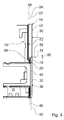
- the household appliance shutter device has a carrier unit 10 with a first, arranged on the support unit 10, a first front surface 12 forming, transparent panel member 14 which is formed by a straight, plate-shaped component ( FIGS. 2, 3 and 4 ).
- the household appliance shutter device comprises a second diaphragm element 20, which is adjacent to the first diaphragm element 14 in its lower edge region 16 and forms a second front surface 18, which is formed by a sheet steel.
- the front surfaces 12, 18 are aligned parallel to a front surface 82 formed by a front screen 80 of the cooking appliance door 74.
- display elements 84 are arranged in a front view on the domestic appliance panel device, in the vertical direction 90 to the first front surface 12 under the panel element 14, while controls 86 are arranged in the area of the second panel element 20. In the area of the operating elements 86, recesses are introduced into the second panel element 20.
- the first front surface 12 of the first diaphragm element 14 and the second front surface 18 of the second diaphragm element 20 are arranged in differing depth planes 22, 24, ie the depth planes 22, 24 are arranged in a front view on the domestic appliance shutter device, spaced in the vertical direction 90 to the first front surface 12 , and with a distance of about 2 mm ( FIG. 4 ).
- the first front surface 12 of the first diaphragm element 14 is arranged in a higher depth plane 22 than the second front surface 18 of the second diaphragm element 20, ie the first front surface 12 of the first diaphragm element 14 is arranged in the direction 90 in front of the second front surface 18 of the second diaphragm element 20, and although in particular also in a transition region 26 of the front surfaces 12, 18, so that in the transition region 26 a paragraph between the first front surface 12 and the second front surface 18 is present.
- the higher depth plane 22 is arranged closer to the viewer than the deeper depth plane 24th
- the first panel member 14 has in the lower edge region on an end face, which is aligned by a perpendicular to the first front surface 12 aligned end face 88 and a Inclined surface is formed by a produced by a grinding process bevel 56, ie from a facet is formed ( FIG. 4 ).
- the chamfer 56 is arranged in a front view in the vertical direction 90 to the front surfaces 12, 18 completely in front of the front surface 18 ( FIG. 4 ).
- the second diaphragm element 20 is in the vertical direction 90 to the front surfaces 12, 18 after the bevel 56 on the end face 88 at.
- the household appliance shutter device comprises a third diaphragm element 36 (FIG. 3) forming a third front surface 32, 34 adjoining the first diaphragm element 14 in side regions 28, 30 of the first diaphragm element 14 (FIG. FIG. 2 ).
- the first front surface 12 of the first diaphragm element 14 and the front surfaces 32, 34 of the third diaphragm element 36 are arranged flush in a common depth plane 22, ie flush with a front side (FIG. Figures 2 and 4 ).
- the second diaphragm element 20 and the third diaphragm element 36 are integrally formed, and both are made of a one-piece sheet metal part in a stamped-stamping process.
- bevels 38, 40 comprising oblique faces are formed between the second facing element 20 and the third facing element 36, in an embossing process.
- side edges 42, 44 of the first panel element 14 and shaped edges 46, 48 of the paragraphs 38, 40 are each arranged in straight lines, which are aligned perpendicular to a main longitudinal extension of the first panel member 14 and the household appliance shutter device.
- the first panel element 14 is fixed in three directions 50, 52, 54 directly positively by the second and the third panel member 20, 36 in its position on the support unit 10, in the longitudinal direction of the household device device device extending directions 50, 52 and in the in a mounting position, vertical downward direction 54 (FIG. FIG. 2 ).
- the first diaphragm element 14 has in its lower edge region 16 in the direction of the second diaphragm element 20 a convexly curved edge over which the first diaphragm element 14 rests against a concavely curved edge of the second diaphragm element 20 over its entire length.
- the second panel element 20 and the third panel element 36 extend together over the entire width of the cooking appliance and form a substantially U-shaped frame, in the first aperture element 14, which extends over more than 50%, in particular more than 70% of the total width of the cooking appliance, is held in a form-fitting manner.
- the carrier unit 10 produced by means of an embossing process has three diaphragm support surfaces 64, 66, 68 arranged on different depth planes 58, 60, 62, namely an diaphragm support surface 64 for the first diaphragm element 14, a diaphragm support surface 66 for the second diaphragm element 20 and two lateral diaphragm support surfaces 68 for the third diaphragm element 36 (FIG. Figures 3 and 4 ).
- a height difference between the most deeply embossed diaphragm support surface 64 and the lateral forwardly embossed highest diaphragm support surfaces 68 corresponds to a material thickness of the first diaphragm element 14 minus a material thickness of the second diaphragm element 20.
- the household appliance shutter device comprises an adhesive film 70, which is provided for fastening the first diaphragm element 14, the second diaphragm element 20 and the third diaphragm element 36 on the carrier unit 10.
- the adhesive film 70 in each case has dividing lines 72 formed by perforations in the region between the diaphragm elements 14, 20, 36, so that the adhesive film 70 can be transported integrally with the carrier unit 10 during an adhesion process and divided into four parts simply without tools during connection to the carrier unit 10 in an upper part for the first diaphragm element 14, a lower part for the second diaphragm element 20 and two lateral parts for the third diaphragm element 36.
Landscapes
- Engineering & Computer Science (AREA)
- Chemical & Material Sciences (AREA)
- Combustion & Propulsion (AREA)
- Mechanical Engineering (AREA)
- General Engineering & Computer Science (AREA)
- Cookers (AREA)
- Housings, Intake/Discharge, And Installation Of Fluid Heaters (AREA)
Priority Applications (1)
| Application Number | Priority Date | Filing Date | Title |
|---|---|---|---|
| PL09164283T PL2141416T3 (pl) | 2008-07-02 | 2009-07-01 | Przyrząd przesłaniający do urządzenia gospodarstwa domowego |
Applications Claiming Priority (1)
| Application Number | Priority Date | Filing Date | Title |
|---|---|---|---|
| DE102008031246A DE102008031246A1 (de) | 2008-07-02 | 2008-07-02 | Haushaltsgeräteblendenvorrichtung |
Publications (3)
| Publication Number | Publication Date |
|---|---|
| EP2141416A2 true EP2141416A2 (fr) | 2010-01-06 |
| EP2141416A3 EP2141416A3 (fr) | 2012-03-07 |
| EP2141416B1 EP2141416B1 (fr) | 2017-09-06 |
Family
ID=41258415
Family Applications (1)
| Application Number | Title | Priority Date | Filing Date |
|---|---|---|---|
| EP09164283.5A Active EP2141416B1 (fr) | 2008-07-02 | 2009-07-01 | Panneau d'appareils ménagers |
Country Status (3)
| Country | Link |
|---|---|
| EP (1) | EP2141416B1 (fr) |
| DE (1) | DE102008031246A1 (fr) |
| PL (1) | PL2141416T3 (fr) |
Cited By (1)
| Publication number | Priority date | Publication date | Assignee | Title |
|---|---|---|---|---|
| EP2527748A1 (fr) * | 2011-05-25 | 2012-11-28 | BSH Bosch und Siemens Hausgeräte GmbH | Four équipé d'un panneau avant |
Families Citing this family (2)
| Publication number | Priority date | Publication date | Assignee | Title |
|---|---|---|---|---|
| DE102016218812A1 (de) | 2016-09-29 | 2018-03-29 | BSH Hausgeräte GmbH | Haushaltsgerät |
| DE102016218807A1 (de) | 2016-09-29 | 2018-03-29 | BSH Hausgeräte GmbH | Haushaltsgerät |
Citations (1)
| Publication number | Priority date | Publication date | Assignee | Title |
|---|---|---|---|---|
| DE10157221A1 (de) | 2001-11-22 | 2003-06-05 | Bsh Bosch Siemens Hausgeraete | Blendeneinheit für ein Gargerät |
Family Cites Families (12)
| Publication number | Priority date | Publication date | Assignee | Title |
|---|---|---|---|---|
| DE2554381C3 (de) * | 1975-12-03 | 1983-04-14 | Bosch-Siemens Hausgeräte GmbH, 7000 Stuttgart | Schaltpult für elektrische Hausgeräte, insbesondere für Herde |
| DE3008202A1 (de) * | 1980-03-04 | 1981-09-17 | Licentia Patent-Verwaltungs-Gmbh, 6000 Frankfurt | Haushaltgeraet, insbesondere zum einbau in kuechenmoebelzeilen bestimmte geschirrspuel- oder waeschebehandlungsmaschine |
| DE3621436A1 (de) * | 1986-06-26 | 1988-01-14 | Bosch Siemens Hausgeraete | Bedien- und anzeigevorrichtung fuer hausgeraete |
| DE8905799U1 (de) * | 1989-05-09 | 1989-06-29 | Bosch-Siemens Hausgeräte GmbH, 8000 München | Schalterblende für ein elektrisches Haushaltgerät, insb. Geschirrspül-, Waschmaschine, Wäschetrockner, Herd o.dgl. |
| DE4140820A1 (de) * | 1991-12-11 | 1993-06-17 | Miele & Cie | Bedienblende fuer haushalt-grossgeraete |
| DE10051075A1 (de) * | 2000-10-14 | 2002-04-25 | Aeg Hausgeraete Gmbh | Verfahren zum Herstellen unterschiedlicher Bedienblenden für Haushaltsgeräte und ein Haushaltsgerät |
| DE10302797B4 (de) * | 2003-01-24 | 2025-05-28 | BSH Hausgeräte GmbH | Tür für ein Kältegerät und Kältegerät, umfassend eine Tür |
| JP2005273943A (ja) * | 2004-03-23 | 2005-10-06 | Toshiba Corp | 冷蔵庫 |
| JP4109220B2 (ja) * | 2004-06-08 | 2008-07-02 | リンナイ株式会社 | グリル付コンロ |
| DE102006001246A1 (de) * | 2006-01-10 | 2007-07-12 | BSH Bosch und Siemens Hausgeräte GmbH | Bedienmodul |
| DE202007002887U1 (de) * | 2007-02-28 | 2007-04-19 | Störk-Tronic, Störk GmbH & Co KG | Bediensystem |
| DE202007003428U1 (de) * | 2007-03-07 | 2007-05-03 | BSH Bosch und Siemens Hausgeräte GmbH | Kältegerät |
-
2008
- 2008-07-02 DE DE102008031246A patent/DE102008031246A1/de not_active Withdrawn
-
2009
- 2009-07-01 EP EP09164283.5A patent/EP2141416B1/fr active Active
- 2009-07-01 PL PL09164283T patent/PL2141416T3/pl unknown
Patent Citations (1)
| Publication number | Priority date | Publication date | Assignee | Title |
|---|---|---|---|---|
| DE10157221A1 (de) | 2001-11-22 | 2003-06-05 | Bsh Bosch Siemens Hausgeraete | Blendeneinheit für ein Gargerät |
Cited By (1)
| Publication number | Priority date | Publication date | Assignee | Title |
|---|---|---|---|---|
| EP2527748A1 (fr) * | 2011-05-25 | 2012-11-28 | BSH Bosch und Siemens Hausgeräte GmbH | Four équipé d'un panneau avant |
Also Published As
| Publication number | Publication date |
|---|---|
| EP2141416A3 (fr) | 2012-03-07 |
| PL2141416T3 (pl) | 2018-03-30 |
| EP2141416B1 (fr) | 2017-09-06 |
| DE102008031246A1 (de) | 2010-01-07 |
Similar Documents
| Publication | Publication Date | Title |
|---|---|---|
| EP2602556A2 (fr) | Dispositif de plan de cuisson | |
| EP2141416B1 (fr) | Panneau d'appareils ménagers | |
| EP4391867B1 (fr) | Panneau latéral pour un tiroir | |
| DE102016204483B4 (de) | Befestigungselement mit mindestens einem Clip zur Herstellung einer Verbindung mit einem korrespondierenden Ansteckelement und Anordnung eines Befestigungselements an einem Ansteckelement | |
| DE102010003901A1 (de) | Aufhängsicherung für Essen und Hauben | |
| EP2251297B1 (fr) | Chariot de manutention doté d'au moins deux éléments d'habillage | |
| EP3727088B1 (fr) | Paroi latérale de tiroir | |
| DE102008042670B4 (de) | Hausgeräterahmen | |
| DE202014100584U1 (de) | Frontblende für Möbel | |
| DE102015209348B4 (de) | Anordnung eines Einfüllstutzens an einem Trägerteil eines Kraftfahrzeuges | |
| DE102004048532B4 (de) | Vorrichtung | |
| DE102007031479B4 (de) | Haushaltsgerät mit einem Bedienmodul | |
| DE202004013917U1 (de) | Gargerätemuffel | |
| DE9007630U1 (de) | Heizkörperverkleidung | |
| DE10157221A1 (de) | Blendeneinheit für ein Gargerät | |
| EP2369240A1 (fr) | Porte d'appareil de cuisson | |
| DE102008013004A1 (de) | Anordnung mit einem Kochfeld und einer Arbeitsplatte | |
| EP1046451B1 (fr) | Appareil pour entailler des profilés | |
| EP2606284B1 (fr) | Hotte aspirante | |
| EP3029244B1 (fr) | Dispositif de recouvrement pour un raccord | |
| EP4030103B1 (fr) | Plaque de cuisson avec boîtier de commande | |
| DE19810188C2 (de) | Klinge für Mähmesser | |
| DE102012208659B4 (de) | Halteeinrichtung für eine Türscheibe einer Gargerätetür und Gargerätetür | |
| DE102016202768A1 (de) | Kochfeldvorrichtung | |
| AT507135A2 (de) | Schliessblech und stulp und deren verwendung |
Legal Events
| Date | Code | Title | Description |
|---|---|---|---|
| PUAI | Public reference made under article 153(3) epc to a published international application that has entered the european phase |
Free format text: ORIGINAL CODE: 0009012 |
|
| AK | Designated contracting states |
Kind code of ref document: A2 Designated state(s): AT BE BG CH CY CZ DE DK EE ES FI FR GB GR HR HU IE IS IT LI LT LU LV MC MK MT NL NO PL PT RO SE SI SK SM TR |
|
| PUAL | Search report despatched |
Free format text: ORIGINAL CODE: 0009013 |
|
| AK | Designated contracting states |
Kind code of ref document: A3 Designated state(s): AT BE BG CH CY CZ DE DK EE ES FI FR GB GR HR HU IE IS IT LI LT LU LV MC MK MT NL NO PL PT RO SE SI SK SM TR |
|
| RIC1 | Information provided on ipc code assigned before grant |
Ipc: F24C 7/08 20060101ALI20120127BHEP Ipc: D06F 39/00 20060101ALI20120127BHEP Ipc: A47L 15/42 20060101ALI20120127BHEP Ipc: F24C 15/00 20060101AFI20120127BHEP |
|
| 17P | Request for examination filed |
Effective date: 20120907 |
|
| 17Q | First examination report despatched |
Effective date: 20130618 |
|
| RAP1 | Party data changed (applicant data changed or rights of an application transferred) |
Owner name: BSH HAUSGERAETE GMBH |
|
| GRAP | Despatch of communication of intention to grant a patent |
Free format text: ORIGINAL CODE: EPIDOSNIGR1 |
|
| INTG | Intention to grant announced |
Effective date: 20170407 |
|
| GRAS | Grant fee paid |
Free format text: ORIGINAL CODE: EPIDOSNIGR3 |
|
| GRAA | (expected) grant |
Free format text: ORIGINAL CODE: 0009210 |
|
| AK | Designated contracting states |
Kind code of ref document: B1 Designated state(s): AT BE BG CH CY CZ DE DK EE ES FI FR GB GR HR HU IE IS IT LI LT LU LV MC MK MT NL NO PL PT RO SE SI SK SM TR |
|
| REG | Reference to a national code |
Ref country code: GB Ref legal event code: FG4D Free format text: NOT ENGLISH |
|
| REG | Reference to a national code |
Ref country code: CH Ref legal event code: EP Ref country code: AT Ref legal event code: REF Ref document number: 926300 Country of ref document: AT Kind code of ref document: T Effective date: 20170915 |
|
| REG | Reference to a national code |
Ref country code: IE Ref legal event code: FG4D Free format text: LANGUAGE OF EP DOCUMENT: GERMAN |
|
| REG | Reference to a national code |
Ref country code: DE Ref legal event code: R096 Ref document number: 502009014321 Country of ref document: DE |
|
| REG | Reference to a national code |
Ref country code: NL Ref legal event code: MP Effective date: 20170906 |
|
| REG | Reference to a national code |
Ref country code: LT Ref legal event code: MG4D |
|
| PG25 | Lapsed in a contracting state [announced via postgrant information from national office to epo] |
Ref country code: FI Free format text: LAPSE BECAUSE OF FAILURE TO SUBMIT A TRANSLATION OF THE DESCRIPTION OR TO PAY THE FEE WITHIN THE PRESCRIBED TIME-LIMIT Effective date: 20170906 Ref country code: NO Free format text: LAPSE BECAUSE OF FAILURE TO SUBMIT A TRANSLATION OF THE DESCRIPTION OR TO PAY THE FEE WITHIN THE PRESCRIBED TIME-LIMIT Effective date: 20171206 Ref country code: HR Free format text: LAPSE BECAUSE OF FAILURE TO SUBMIT A TRANSLATION OF THE DESCRIPTION OR TO PAY THE FEE WITHIN THE PRESCRIBED TIME-LIMIT Effective date: 20170906 Ref country code: SE Free format text: LAPSE BECAUSE OF FAILURE TO SUBMIT A TRANSLATION OF THE DESCRIPTION OR TO PAY THE FEE WITHIN THE PRESCRIBED TIME-LIMIT Effective date: 20170906 Ref country code: LT Free format text: LAPSE BECAUSE OF FAILURE TO SUBMIT A TRANSLATION OF THE DESCRIPTION OR TO PAY THE FEE WITHIN THE PRESCRIBED TIME-LIMIT Effective date: 20170906 |
|
| PG25 | Lapsed in a contracting state [announced via postgrant information from national office to epo] |
Ref country code: LV Free format text: LAPSE BECAUSE OF FAILURE TO SUBMIT A TRANSLATION OF THE DESCRIPTION OR TO PAY THE FEE WITHIN THE PRESCRIBED TIME-LIMIT Effective date: 20170906 Ref country code: BG Free format text: LAPSE BECAUSE OF FAILURE TO SUBMIT A TRANSLATION OF THE DESCRIPTION OR TO PAY THE FEE WITHIN THE PRESCRIBED TIME-LIMIT Effective date: 20171206 Ref country code: ES Free format text: LAPSE BECAUSE OF FAILURE TO SUBMIT A TRANSLATION OF THE DESCRIPTION OR TO PAY THE FEE WITHIN THE PRESCRIBED TIME-LIMIT Effective date: 20170906 Ref country code: GR Free format text: LAPSE BECAUSE OF FAILURE TO SUBMIT A TRANSLATION OF THE DESCRIPTION OR TO PAY THE FEE WITHIN THE PRESCRIBED TIME-LIMIT Effective date: 20171207 |
|
| PG25 | Lapsed in a contracting state [announced via postgrant information from national office to epo] |
Ref country code: NL Free format text: LAPSE BECAUSE OF FAILURE TO SUBMIT A TRANSLATION OF THE DESCRIPTION OR TO PAY THE FEE WITHIN THE PRESCRIBED TIME-LIMIT Effective date: 20170906 |
|
| PG25 | Lapsed in a contracting state [announced via postgrant information from national office to epo] |
Ref country code: RO Free format text: LAPSE BECAUSE OF FAILURE TO SUBMIT A TRANSLATION OF THE DESCRIPTION OR TO PAY THE FEE WITHIN THE PRESCRIBED TIME-LIMIT Effective date: 20170906 Ref country code: CZ Free format text: LAPSE BECAUSE OF FAILURE TO SUBMIT A TRANSLATION OF THE DESCRIPTION OR TO PAY THE FEE WITHIN THE PRESCRIBED TIME-LIMIT Effective date: 20170906 |
|
| PG25 | Lapsed in a contracting state [announced via postgrant information from national office to epo] |
Ref country code: IT Free format text: LAPSE BECAUSE OF FAILURE TO SUBMIT A TRANSLATION OF THE DESCRIPTION OR TO PAY THE FEE WITHIN THE PRESCRIBED TIME-LIMIT Effective date: 20170906 Ref country code: SM Free format text: LAPSE BECAUSE OF FAILURE TO SUBMIT A TRANSLATION OF THE DESCRIPTION OR TO PAY THE FEE WITHIN THE PRESCRIBED TIME-LIMIT Effective date: 20170906 Ref country code: EE Free format text: LAPSE BECAUSE OF FAILURE TO SUBMIT A TRANSLATION OF THE DESCRIPTION OR TO PAY THE FEE WITHIN THE PRESCRIBED TIME-LIMIT Effective date: 20170906 Ref country code: IS Free format text: LAPSE BECAUSE OF FAILURE TO SUBMIT A TRANSLATION OF THE DESCRIPTION OR TO PAY THE FEE WITHIN THE PRESCRIBED TIME-LIMIT Effective date: 20180106 Ref country code: SK Free format text: LAPSE BECAUSE OF FAILURE TO SUBMIT A TRANSLATION OF THE DESCRIPTION OR TO PAY THE FEE WITHIN THE PRESCRIBED TIME-LIMIT Effective date: 20170906 |
|
| REG | Reference to a national code |
Ref country code: DE Ref legal event code: R097 Ref document number: 502009014321 Country of ref document: DE |
|
| PLBE | No opposition filed within time limit |
Free format text: ORIGINAL CODE: 0009261 |
|
| STAA | Information on the status of an ep patent application or granted ep patent |
Free format text: STATUS: NO OPPOSITION FILED WITHIN TIME LIMIT |
|
| PG25 | Lapsed in a contracting state [announced via postgrant information from national office to epo] |
Ref country code: DK Free format text: LAPSE BECAUSE OF FAILURE TO SUBMIT A TRANSLATION OF THE DESCRIPTION OR TO PAY THE FEE WITHIN THE PRESCRIBED TIME-LIMIT Effective date: 20170906 |
|
| 26N | No opposition filed |
Effective date: 20180607 |
|
| PG25 | Lapsed in a contracting state [announced via postgrant information from national office to epo] |
Ref country code: SI Free format text: LAPSE BECAUSE OF FAILURE TO SUBMIT A TRANSLATION OF THE DESCRIPTION OR TO PAY THE FEE WITHIN THE PRESCRIBED TIME-LIMIT Effective date: 20170906 |
|
| PG25 | Lapsed in a contracting state [announced via postgrant information from national office to epo] |
Ref country code: MT Free format text: LAPSE BECAUSE OF FAILURE TO SUBMIT A TRANSLATION OF THE DESCRIPTION OR TO PAY THE FEE WITHIN THE PRESCRIBED TIME-LIMIT Effective date: 20170906 |
|
| REG | Reference to a national code |
Ref country code: CH Ref legal event code: PL |
|
| GBPC | Gb: european patent ceased through non-payment of renewal fee |
Effective date: 20180701 |
|
| PG25 | Lapsed in a contracting state [announced via postgrant information from national office to epo] |
Ref country code: LU Free format text: LAPSE BECAUSE OF NON-PAYMENT OF DUE FEES Effective date: 20180701 Ref country code: MC Free format text: LAPSE BECAUSE OF FAILURE TO SUBMIT A TRANSLATION OF THE DESCRIPTION OR TO PAY THE FEE WITHIN THE PRESCRIBED TIME-LIMIT Effective date: 20170906 |
|
| REG | Reference to a national code |
Ref country code: BE Ref legal event code: MM Effective date: 20180731 |
|
| REG | Reference to a national code |
Ref country code: IE Ref legal event code: MM4A |
|
| PG25 | Lapsed in a contracting state [announced via postgrant information from national office to epo] |
Ref country code: LI Free format text: LAPSE BECAUSE OF NON-PAYMENT OF DUE FEES Effective date: 20180731 Ref country code: GB Free format text: LAPSE BECAUSE OF NON-PAYMENT OF DUE FEES Effective date: 20180701 Ref country code: IE Free format text: LAPSE BECAUSE OF NON-PAYMENT OF DUE FEES Effective date: 20180701 Ref country code: CH Free format text: LAPSE BECAUSE OF NON-PAYMENT OF DUE FEES Effective date: 20180731 Ref country code: FR Free format text: LAPSE BECAUSE OF NON-PAYMENT OF DUE FEES Effective date: 20180731 |
|
| PG25 | Lapsed in a contracting state [announced via postgrant information from national office to epo] |
Ref country code: BE Free format text: LAPSE BECAUSE OF NON-PAYMENT OF DUE FEES Effective date: 20180731 |
|
| REG | Reference to a national code |
Ref country code: AT Ref legal event code: MM01 Ref document number: 926300 Country of ref document: AT Kind code of ref document: T Effective date: 20180701 |
|
| PG25 | Lapsed in a contracting state [announced via postgrant information from national office to epo] |
Ref country code: AT Free format text: LAPSE BECAUSE OF NON-PAYMENT OF DUE FEES Effective date: 20180701 |
|
| PG25 | Lapsed in a contracting state [announced via postgrant information from national office to epo] |
Ref country code: HU Free format text: LAPSE BECAUSE OF FAILURE TO SUBMIT A TRANSLATION OF THE DESCRIPTION OR TO PAY THE FEE WITHIN THE PRESCRIBED TIME-LIMIT; INVALID AB INITIO Effective date: 20090701 Ref country code: PT Free format text: LAPSE BECAUSE OF FAILURE TO SUBMIT A TRANSLATION OF THE DESCRIPTION OR TO PAY THE FEE WITHIN THE PRESCRIBED TIME-LIMIT Effective date: 20170906 |
|
| PG25 | Lapsed in a contracting state [announced via postgrant information from national office to epo] |
Ref country code: CY Free format text: LAPSE BECAUSE OF FAILURE TO SUBMIT A TRANSLATION OF THE DESCRIPTION OR TO PAY THE FEE WITHIN THE PRESCRIBED TIME-LIMIT Effective date: 20170906 Ref country code: MK Free format text: LAPSE BECAUSE OF NON-PAYMENT OF DUE FEES Effective date: 20170906 |
|
| PGFP | Annual fee paid to national office [announced via postgrant information from national office to epo] |
Ref country code: TR Payment date: 20220624 Year of fee payment: 14 Ref country code: PL Payment date: 20220624 Year of fee payment: 14 |
|
| PGFP | Annual fee paid to national office [announced via postgrant information from national office to epo] |
Ref country code: DE Payment date: 20220731 Year of fee payment: 14 |
|
| REG | Reference to a national code |
Ref country code: DE Ref legal event code: R119 Ref document number: 502009014321 Country of ref document: DE |
|
| PG25 | Lapsed in a contracting state [announced via postgrant information from national office to epo] |
Ref country code: DE Free format text: LAPSE BECAUSE OF NON-PAYMENT OF DUE FEES Effective date: 20240201 |
|
| PG25 | Lapsed in a contracting state [announced via postgrant information from national office to epo] |
Ref country code: PL Free format text: LAPSE BECAUSE OF NON-PAYMENT OF DUE FEES Effective date: 20230701 |
|
| PG25 | Lapsed in a contracting state [announced via postgrant information from national office to epo] |
Ref country code: PL Free format text: LAPSE BECAUSE OF NON-PAYMENT OF DUE FEES Effective date: 20230701 |