EP2141476A2 - System und Verfahren zur Analyse der Reifengleichförmigkeit - Google Patents
System und Verfahren zur Analyse der Reifengleichförmigkeit Download PDFInfo
- Publication number
- EP2141476A2 EP2141476A2 EP08171657A EP08171657A EP2141476A2 EP 2141476 A2 EP2141476 A2 EP 2141476A2 EP 08171657 A EP08171657 A EP 08171657A EP 08171657 A EP08171657 A EP 08171657A EP 2141476 A2 EP2141476 A2 EP 2141476A2
- Authority
- EP
- European Patent Office
- Prior art keywords
- tire
- image
- recited
- uniformity
- deformation
- Prior art date
- Legal status (The legal status is an assumption and is not a legal conclusion. Google has not performed a legal analysis and makes no representation as to the accuracy of the status listed.)
- Granted
Links
- 238000000034 method Methods 0.000 title claims abstract description 22
- 238000006073 displacement reaction Methods 0.000 claims description 7
- 230000001131 transforming effect Effects 0.000 claims description 5
- 238000012545 processing Methods 0.000 claims description 4
- 238000012360 testing method Methods 0.000 abstract description 11
- 238000005259 measurement Methods 0.000 abstract description 6
- 230000008569 process Effects 0.000 abstract description 5
- 230000008859 change Effects 0.000 description 7
- 239000000126 substance Substances 0.000 description 3
- 239000003086 colorant Substances 0.000 description 2
- 238000012937 correction Methods 0.000 description 2
- 230000006870 function Effects 0.000 description 2
- 239000004922 lacquer Substances 0.000 description 2
- 239000000463 material Substances 0.000 description 2
- 239000011324 bead Substances 0.000 description 1
- 238000001816 cooling Methods 0.000 description 1
- 230000001627 detrimental effect Effects 0.000 description 1
- 238000012986 modification Methods 0.000 description 1
- 230000004048 modification Effects 0.000 description 1
- 230000000704 physical effect Effects 0.000 description 1
- 238000012552 review Methods 0.000 description 1
Images


Classifications
-
- G—PHYSICS
- G01—MEASURING; TESTING
- G01M—TESTING STATIC OR DYNAMIC BALANCE OF MACHINES OR STRUCTURES; TESTING OF STRUCTURES OR APPARATUS, NOT OTHERWISE PROVIDED FOR
- G01M17/00—Testing of vehicles
- G01M17/007—Wheeled or endless-tracked vehicles
- G01M17/02—Tyres
- G01M17/027—Tyres using light, e.g. infrared, ultraviolet or holographic techniques
Definitions
- the present invention relates generally to a system for analyzing tire uniformity, and more particularly to a system for analyzing tire uniformity which enables the uniformity analysis process to be performed in a short period of time with precision and the uniformity measurement not to be affected by the condition of a test center.
- a green tire is manufactured on a tire building drum by way of disposing a variety of rubber products in turn, including an inner liner, carcass, belt structure, tread portion, sidewall portion, bead portion or the like that are partly manufactured in the separate processes.
- the resulting green tire is then put into a mold and vulcanized at an elevated temperature (approximately 120-150 °C) for a period of time (approximately 10-30 minutes), and after substantially cooling down a finished tire having a required configuration and physical property is obtained.
- an elevated temperature approximately 120-150 °C
- a period of time approximately 10-30 minutes
- a series of tests are performed on the finished tire in order to evaluate the quality of the tire whether the tire falls within a certain range of uniformity characteristics.
- uniformity is defined as what characteristics a perfect or ideal tire would have for a measured characteristic when tested.
- the uniformity characteristics can be depicted as a deviation from perfect roundness of the outer circumference of the tire.
- the uniformity characteristics consist of a low threshold value and a high threshold value. If the tested uniformity of a tire is below the low threshold value, the deformation of the tire seems not detrimental to a vehicle ride and thus the tire can be distributed for sale. On the other hand, if the tested uniformity of a tire is over the high threshold value, the tire may be discarded or scrapped. If the tested uniformity of a tire is between the low threshold value and the high threshold value, the tire may be salable after correction for uniformity.
- the tire having uniformity over the high threshold value generally causes undesirable vibration, noise or severe wear while driving the vehicle, which seems to deteriorate the comfort of the ride as well as shorten the lifetime of the tire.
- a variety of devices and methods for measuring and correcting the uniformity of a tire are known and described, for example, in U.S. Patent No. 4,458,526 , U.S. Patent No. 5,022,186 , U.S. Patent No. 5,103,669 or U.S. Patent No. 5,365,781 .
- a tire uniformity tester or tire uniformity measuring machine is generally used to measure the uniformity of the tire.
- An inflated tire is mounted on the uniformity test machine and rotated at a predetermined speed.
- the lateral force exerted by the tire on the machine is then measured to calculate the force variation or uniformity characteristics in the tire during rotation.
- the uniformity characteristics are further processed in a computer to obtain information for correction of a tire.
- the uniformity tests as described hereinabove are disadvantageous in that they require a large amount of time because the test comprises of various steps to be performed in turn and needs repetitious measurement to get a target value. Further, it can be noted that the tire uniformity measurement may include an erroneous contribution from the uniformity test machine itself, which requires another step to identify and remove the contribution from the uniformity test machine.
- a point scanning method is proposed in the art, wherein a laser pointer is used to scan every entire surface of a tire to being tested.
- This point scanning method turned out to have the drawbacks that the scanning work is time consuming, and more importantly the uniformity measurement has substantially high error probability depending on the condition of a test center.
- Another object of the invention is to provide a method for analyzing tire uniformity capable of performing the entire uniformity analysis in a short period of time with greater simplicity and efficiency.
- a system for analyzing tire uniformity comprising a light source for illuminating light on a tire to being tested; a diffraction grating disposed on the same axis line between the light source and the tire for producing light having a sine pattern; a photographing means disposed in a certain angular relationship with the tire for taking an image of the tire having the sine pattern on its outer surface projected through the diffraction grating; and an analyzer for processing the image of the tire having the sine pattern on its surface to determine uniformity of the tire.
- the system further comprises of a lens equipped with a diffraction grating in unitary fashion and disposed on the same axis line between a light source and a tire to being tested for focusing the light emanating from the light source on the tire.
- I A x ⁇ y ⁇ sin ⁇ x ⁇ y + 1
- I the intensity of light as a function of position
- ⁇ an angle at which the light is incident on the tire
- A an integer
- the analyzer outputs the phase information in the form of either an image having various color levels or a numerical data on the basis of the angular position of the tire. That is, the analyzer calculates the amount of deformation on the tire by transforming the difference of phase information between an ideal tire (having no deformation) and a tire being tested (having deformation). The analyzer is then subjected to display the amount of actual deformation between the two tires in the form of either an image having various colors or numerals on the monitor screen.
- a method for analyzing a tire uniformity comprising the steps of illuminating light passed through a sine diffraction grating on the surface of a tire to being tested; photographing an image of the tire having the sine pattern projected on its surface by a diffraction grating; and analyzing the image of the sine pattern to determine the uniformity of the tire.
- FIG. 1 is a schematic configuration of a system for analyzing tire uniformity in accordance with a preferred embodiment of the invention.
- the system for analyzing tire uniformity 1 comprises a light source 5 for illuminating light on a tire 30 to being tested, a sine diffraction grating 15 with a lens 10 disposed on the same axis line between the light source 5 and the tire 30 for producing light having a sine pattern, a photographing means 20 for taking an image of the tire 30 in which the sine pattern is projected on its outer surface by the diffracted light passing through the diffraction grating 15, and an analyzer 25 for determining a uniformity of the tire 30 by analyzing the sine pattern formed on the surface of the tire 30.
- the light source 5 irradiates light having enough intensity to allow the light to be incident with a predetermined angle on the surface of the tire 30 through both the lens 10 and the sin diffraction grating 15.
- the lens 10 is a conventional lens being used in the art, but alternatively, the lens 10 may be provided with a sine diffraction grating 15 in unitary fashion and formed in circular, rectangular shape or the like.
- the sine diffraction grating 15 is generally provided within the lens 10, and the light passing through the sine diffraction grating 15 is irradiated on the surface of the tire 30, wherein the sine pattern having a plurality of long stripes is projected on the tire surface.
- various type of photographing devices can be adopted as a digital camera 20, but preferably a digital camera is suitable for the inventive system for analyzing the tire uniformity.
- the photographing means will be described as a digital camera 20 hereinbelow.
- the light source 5 and the lens 10 are spaced apart on the same axis line toward the tire 30, while making the light emanating from the light source 5 incident on the tire 30 with a certain angle.
- the digital camera 20 is positioned horizontally with respect to the tire 30, thereby maintaining a predetermined angular relationship with the light source 5 and the lens 10.
- the digital camera 20 is positioned to face the tire 30 such that the digital camera 20 can take an image depicting the side elevational view of the tire 30.
- the surface of the tire 30 is applied with a white substance, preferably a powder-like material or lacquer so that a clear and distinct image having the sine pattern can be obtained by the digital camera 20.
- the analyzer 25 includes a computer (not shown) provided with a monitor (not shown), wherein a processed image is displayed on the monitor screen by analyzing the uniformity characteristics of the tire 30.
- the uniformity characteristics of the tire 30 are calculated from the image of the tire 30 taken by the digital camera 20. That is, the analyzer 25 determines the uniformity characteristics of the tire 30 using several Formulae described below, wherein the analyzer 25 analyzes the image of the sine pattern projected on the tire surface.
- FIG. 2 an exemplary image taken by the digital camera 20 is shown in FIG. 2 .
- FIG. 2 With processing the Fourier analysis on the Formula 3, the image shown in FIG. 2 will be transformed into the image as depicted in FIG. 3 .
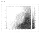
- the numerals located on the horizontal axis and the vertical axis in FIGS. 3 through 5 and FIG. 8 represent the size of the image.
- FIG. 4 we have an image as shown in FIG. 4 , wherein the imaginary part is removed and only the real part remains so as to illustrate the image clearer.
- inverse Fourier transform of the Formula 4 we have an image as depicted in FIG. 5 that has phase information of the tire 30.
- a legend on the right side of FIG. 5 illustrates the change of the phase information in the form of color level or numerals. Therefore, with reference to FIG. 5 , the change of the phase information of the tire can be displayed on the monitor either in color changes corresponding to the image of the tire or in numerals quantitatively calculated from phase information of the tire.
- the image on the monitor will be seen in one color in case the tire has no deformation. Meanwhile, if the tire is uneven due to deformation, the image will be displayed in different colors or patterns as shown in FIG. 5 .
- Displacement information corresponding to respective phase information of the tire is stored at a memory means in the analyzer 25. Such displacement information will be displayed on the monitor screen in numerals according to user's option.
- the analyzer 25 will display the amount of deformation by comparing the phase information between a deformed tire and an undeformed tire.
- FIG. 6 illustrates an image of a tire before deformation is given to the tire
- FIG. 7 shows an image of a tire after deformation is given to the tire.
- the analyzer 25 processes the image of an ideal or perfect tire, i.e., an undeformed tire as shown in FIG. 6 with the application of the Formula 1 through 4 in sequential manners and outputs the phase information for further processing.
- the analyzer 25 processed the image of a deformed tire as shown in FIG. 6 and calculates the phase information.
- the analyzer 25 compares the above two phase information and calculates a phase difference therebetween.
- the analyzer 25 transforms the phase difference into displacement by Fourier transform as described hereinabove and provides an image in terms of amount of actual deformation to the monitor as illustrated in FIG. 8 .
- a legend on the right side of FIG. 8 illustrates the amount of actual deformation in the form of color change or numerals. Accordingly, with reference to FIG. 8 , the amount of actual deformation in the tire to being tested can be displayed on the monitor in different level of color change. Here, the level of color change is indicative of uniformity characteristics of the tire. In the alternative, the amount of actual deformation in the tire will be numerically displayed on the monitor in terms of numerals quantitatively calculated from the phase difference.
- the test for analyzing uniformity characteristics of a tire begins by applying a white substance, preferably a powder-like material or lacquer on the surface of the tire to being tested. Upon switching on the power, light emanating from the light source 5 will be incident on the surface of the tire 30 through the lens 10. Then a sine pattern is projected on the tire surface by way of the sine diffraction grating 15 provided within the lens 10. Due to the white substance, sine patterns are distinctly formed on the tire surface. Subsequently, the digital camera 20 takes an image of the tire 30 including the sine pattern formed thereon, and the image is directly sent to the analyzer 25.
- a white substance preferably a powder-like material or lacquer
- the analyzer 25 calculates the intensity of light, i.e., the intensity of the image obtained by the digital camera 20 using the Formula 1 as described hereinabove.
- the image taken by the digital camera 20 is transformed into an image as shown in FIG. 3 .
- the image of FIG. 3 is further transformed into an image illustrated in FIG. 4 with simplification of the Formula 3 by removing the imaginary part in the Formula 3.
- the analyzer 25 proceeds an inverse Fourier transform on the Formula 4
- the image depicted in FIG. 4 is changed into an image as shown in FIG. 5 , wherein the image is displayed on the monitor in terms of amount of deformation calculated from the phase difference.
- the amount of actual deformation or change of the phase difference i.e., the uniformity characteristics of the tire. It can be noted as alternatives that the amount of actual deformation in the tire can be numerically displayed on the monitor in terms of numerals quantitatively calculated from the phase difference.
- the variation of radius or width of a tire being tested can be measured in the unloaded state, and a localized deformation in the sidewall can also be inspected without needs of rotating the tire like in the uniformity test machine in the prior art.
- the inventive system is comprised of simple configuration, thereby leaving no limitation on the space for testing operation or installing of the test system.
- the inventive method utilizes a photograph of a tire having a sine pattern on its surface and analyzing the sine pattern by a series of Fourier transform to provide an image or numerical data on the monitor, which enables the entire uniformity analysis to be performed in a short period of time with greater simplicity and efficiency.
Landscapes
- Physics & Mathematics (AREA)
- General Physics & Mathematics (AREA)
- Length Measuring Devices By Optical Means (AREA)
- Tires In General (AREA)
- Engineering & Computer Science (AREA)
- Computer Vision & Pattern Recognition (AREA)
- Health & Medical Sciences (AREA)
- Life Sciences & Earth Sciences (AREA)
- Chemical & Material Sciences (AREA)
- Analytical Chemistry (AREA)
- Biochemistry (AREA)
- General Health & Medical Sciences (AREA)
- Immunology (AREA)
- Pathology (AREA)
Applications Claiming Priority (1)
| Application Number | Priority Date | Filing Date | Title |
|---|---|---|---|
| KR20080064268A KR100998058B1 (ko) | 2008-07-03 | 2008-07-03 | 타이어 균일성 분석 시스템 및 그 분석방법 |
Publications (3)
| Publication Number | Publication Date |
|---|---|
| EP2141476A2 true EP2141476A2 (de) | 2010-01-06 |
| EP2141476A3 EP2141476A3 (de) | 2014-06-25 |
| EP2141476B1 EP2141476B1 (de) | 2016-04-13 |
Family
ID=41127924
Family Applications (1)
| Application Number | Title | Priority Date | Filing Date |
|---|---|---|---|
| EP08171657.3A Not-in-force EP2141476B1 (de) | 2008-07-03 | 2008-12-15 | System und Verfahren zur Analyse der Reifengleichförmigkeit |
Country Status (3)
| Country | Link |
|---|---|
| EP (1) | EP2141476B1 (de) |
| KR (1) | KR100998058B1 (de) |
| CN (1) | CN101620177B (de) |
Cited By (3)
| Publication number | Priority date | Publication date | Assignee | Title |
|---|---|---|---|---|
| US9719944B2 (en) | 2013-07-10 | 2017-08-01 | Pirelli Tyre S.P.A. | Method and apparatus for controlling tyres in a tyre production line |
| US10102616B2 (en) | 2014-01-28 | 2018-10-16 | Ent. Services Development Corporation Lp | Method and system for surface wear determination |
| US10900774B2 (en) | 2016-07-26 | 2021-01-26 | Pirelli Tyre S.P.A. | Method for checking tyres for vehicle wheels |
Families Citing this family (2)
| Publication number | Priority date | Publication date | Assignee | Title |
|---|---|---|---|---|
| KR101108250B1 (ko) * | 2009-11-10 | 2012-02-09 | 한국타이어 주식회사 | 타이어 마모 측정 장치 |
| JP5726045B2 (ja) * | 2011-11-07 | 2015-05-27 | 株式会社神戸製鋼所 | タイヤ形状検査方法、及びタイヤ形状検査装置 |
Citations (4)
| Publication number | Priority date | Publication date | Assignee | Title |
|---|---|---|---|---|
| US4458526A (en) | 1980-11-26 | 1984-07-10 | Kabushiki Kaisha Toyota Chuo Kenkyusho | Apparatus for measuring tire uniformity |
| US5022186A (en) | 1985-11-08 | 1991-06-11 | The Uniroyal Goodrich Tire Company | Tire uniformity correction |
| US5103669A (en) | 1989-10-31 | 1992-04-14 | Kabushiki Kaisha Kobe Seiko Sho | Instrument for measuring uniformity of tire |
| US5365781A (en) | 1992-04-03 | 1994-11-22 | Michelin Recherche Et Technique S.A. | Tire uniformity correction without grinding |
Family Cites Families (7)
| Publication number | Priority date | Publication date | Assignee | Title |
|---|---|---|---|---|
| US4506981A (en) * | 1982-10-14 | 1985-03-26 | The B. F. Goodrich Company | Method for detection of blown beads in pneumatic tires |
| JPH1096611A (ja) * | 1996-07-31 | 1998-04-14 | N S D Kk | 形状測定装置 |
| DE10019387C2 (de) * | 2000-04-19 | 2003-05-15 | Bernward Maehner | Verfahren und Vorrichtung zur Untersuchung von Reifen |
| DE10333802B4 (de) * | 2003-07-24 | 2005-09-08 | Steinbichler Optotechnik Gmbh | Verfahren und Vorrichtung zum Prüfen von Reifen |
| CN100494923C (zh) * | 2003-12-31 | 2009-06-03 | 中国科学院西安光学精密机械研究所 | 空间调制型干涉光谱成像仪星上定标方法 |
| CN1631688A (zh) * | 2004-12-17 | 2005-06-29 | 武汉理工大学 | 一种新型汽车轮胎健康状况监测系统及方法 |
| US7492450B2 (en) * | 2005-10-24 | 2009-02-17 | General Electric Company | Methods and apparatus for inspecting an object |
-
2008
- 2008-07-03 KR KR20080064268A patent/KR100998058B1/ko not_active Expired - Fee Related
- 2008-12-03 CN CN2008101789669A patent/CN101620177B/zh not_active Expired - Fee Related
- 2008-12-15 EP EP08171657.3A patent/EP2141476B1/de not_active Not-in-force
Patent Citations (4)
| Publication number | Priority date | Publication date | Assignee | Title |
|---|---|---|---|---|
| US4458526A (en) | 1980-11-26 | 1984-07-10 | Kabushiki Kaisha Toyota Chuo Kenkyusho | Apparatus for measuring tire uniformity |
| US5022186A (en) | 1985-11-08 | 1991-06-11 | The Uniroyal Goodrich Tire Company | Tire uniformity correction |
| US5103669A (en) | 1989-10-31 | 1992-04-14 | Kabushiki Kaisha Kobe Seiko Sho | Instrument for measuring uniformity of tire |
| US5365781A (en) | 1992-04-03 | 1994-11-22 | Michelin Recherche Et Technique S.A. | Tire uniformity correction without grinding |
Cited By (3)
| Publication number | Priority date | Publication date | Assignee | Title |
|---|---|---|---|---|
| US9719944B2 (en) | 2013-07-10 | 2017-08-01 | Pirelli Tyre S.P.A. | Method and apparatus for controlling tyres in a tyre production line |
| US10102616B2 (en) | 2014-01-28 | 2018-10-16 | Ent. Services Development Corporation Lp | Method and system for surface wear determination |
| US10900774B2 (en) | 2016-07-26 | 2021-01-26 | Pirelli Tyre S.P.A. | Method for checking tyres for vehicle wheels |
Also Published As
| Publication number | Publication date |
|---|---|
| EP2141476B1 (de) | 2016-04-13 |
| EP2141476A3 (de) | 2014-06-25 |
| CN101620177A (zh) | 2010-01-06 |
| CN101620177B (zh) | 2011-08-03 |
| KR100998058B1 (ko) | 2010-12-03 |
| KR20100004218A (ko) | 2010-01-13 |
Similar Documents
| Publication | Publication Date | Title |
|---|---|---|
| US9097514B2 (en) | Device and method for inspecting tyre shape | |
| RU2657637C2 (ru) | Способ и устройство для контроля шин на линии для производства шин | |
| JP6087163B2 (ja) | タイヤユニフォミティマシンを特性化するためのシステムおよびその特性化を使用する方法 | |
| EP2745224B1 (de) | Verfahren und system zur verbesserten reifengleichförmigkeit durch identifikation von prozessharmonischen mit reindizierten partiellen uniformitätswellenformen | |
| RU2640673C1 (ru) | Способ и устройство для детектирования дефектов на шинах в процессе производства шин | |
| KR20140001205A (ko) | 타이어의 트레드 구성을 형성하는 기초 패턴의 식별 및 지정 방법 | |
| EP2141476B1 (de) | System und Verfahren zur Analyse der Reifengleichförmigkeit | |
| US4234256A (en) | Determining depth location of separations within a tire | |
| WO2019022170A1 (ja) | 欠陥検査方法及び欠陥検査装置 | |
| JP2015087364A (ja) | タイヤの検査装置 | |
| JPH09329510A (ja) | 力の検査機を用いるタイヤの均一性分析方法 | |
| JP2017116528A (ja) | タイヤユニフォミティマシンの特性化システムおよび方法 | |
| KR102466857B1 (ko) | 차륜용 타이어 검사 방법 및 장치 | |
| EP3488212B1 (de) | Verfahren und vorrichtung zum prüfen von reifen | |
| CN106289097B (zh) | 轮胎面形状测定方法和轮胎面形状测定装置 | |
| JP2015028478A (ja) | タイヤ均一性装置を評価するためのシステム、及び、評価の使用方法 | |
| KR101697440B1 (ko) | 타이어 가황용 블래더의 편심 검사방법 | |
| EP3175214B1 (de) | Verbesserung der reifengleichförmigkeit durch identifikation von messprozessoberschwingungen | |
| GB2555604A (en) | Vehicle inspection methods and apparatus | |
| JP2019194041A (ja) | タイヤ製造情報の解析方法 | |
| RU2761673C1 (ru) | Способ и устройство для проверки шин | |
| KR20190012479A (ko) | 타이어 비드 진원도 검사 장치 | |
| US20090049902A1 (en) | Method for correcting concave-convex exhibited on a surface of a body of rotation | |
| EP3488213B1 (de) | Verfahren und vorrichtung zur überprüfung von reifen | |
| EP3563137B1 (de) | Verfahren zur prüfung von reifen |
Legal Events
| Date | Code | Title | Description |
|---|---|---|---|
| PUAI | Public reference made under article 153(3) epc to a published international application that has entered the european phase |
Free format text: ORIGINAL CODE: 0009012 |
|
| AK | Designated contracting states |
Kind code of ref document: A2 Designated state(s): AT BE BG CH CY CZ DE DK EE ES FI FR GB GR HR HU IE IS IT LI LT LU LV MC MT NL NO PL PT RO SE SI SK TR |
|
| AX | Request for extension of the european patent |
Extension state: AL BA MK RS |
|
| PUAL | Search report despatched |
Free format text: ORIGINAL CODE: 0009013 |
|
| AK | Designated contracting states |
Kind code of ref document: A3 Designated state(s): AT BE BG CH CY CZ DE DK EE ES FI FR GB GR HR HU IE IS IT LI LT LU LV MC MT NL NO PL PT RO SE SI SK TR |
|
| AX | Request for extension of the european patent |
Extension state: AL BA MK RS |
|
| RIC1 | Information provided on ipc code assigned before grant |
Ipc: G01M 17/02 20060101AFI20140519BHEP |
|
| 17P | Request for examination filed |
Effective date: 20141224 |
|
| RBV | Designated contracting states (corrected) |
Designated state(s): AT BE BG CH CY CZ DE DK EE ES FI FR GB GR HR HU IE IS IT LI LT LU LV MC MT NL NO PL PT RO SE SI SK TR |
|
| AKX | Designation fees paid |
Designated state(s): AT BE BG CH CY CZ DE DK EE ES FI FR GB GR HR HU IE IS IT LI LT LU LV MC MT NL NO PL PT RO SE SI SK TR |
|
| AXX | Extension fees paid |
Extension state: AL Extension state: BA Extension state: RS Extension state: MK |
|
| 17Q | First examination report despatched |
Effective date: 20150211 |
|
| GRAP | Despatch of communication of intention to grant a patent |
Free format text: ORIGINAL CODE: EPIDOSNIGR1 |
|
| INTG | Intention to grant announced |
Effective date: 20150910 |
|
| GRAS | Grant fee paid |
Free format text: ORIGINAL CODE: EPIDOSNIGR3 |
|
| GRAA | (expected) grant |
Free format text: ORIGINAL CODE: 0009210 |
|
| INTG | Intention to grant announced |
Effective date: 20160223 |
|
| AK | Designated contracting states |
Kind code of ref document: B1 Designated state(s): AT BE BG CH CY CZ DE DK EE ES FI FR GB GR HR HU IE IS IT LI LT LU LV MC MT NL NO PL PT RO SE SI SK TR |
|
| REG | Reference to a national code |
Ref country code: GB Ref legal event code: FG4D |
|
| REG | Reference to a national code |
Ref country code: AT Ref legal event code: REF Ref document number: 790649 Country of ref document: AT Kind code of ref document: T Effective date: 20160415 Ref country code: CH Ref legal event code: EP |
|
| REG | Reference to a national code |
Ref country code: IE Ref legal event code: FG4D |
|
| REG | Reference to a national code |
Ref country code: DE Ref legal event code: R096 Ref document number: 602008043457 Country of ref document: DE |
|
| REG | Reference to a national code |
Ref country code: LT Ref legal event code: MG4D |
|
| REG | Reference to a national code |
Ref country code: AT Ref legal event code: MK05 Ref document number: 790649 Country of ref document: AT Kind code of ref document: T Effective date: 20160413 |
|
| REG | Reference to a national code |
Ref country code: NL Ref legal event code: MP Effective date: 20160413 |
|
| PG25 | Lapsed in a contracting state [announced via postgrant information from national office to epo] |
Ref country code: LT Free format text: LAPSE BECAUSE OF FAILURE TO SUBMIT A TRANSLATION OF THE DESCRIPTION OR TO PAY THE FEE WITHIN THE PRESCRIBED TIME-LIMIT Effective date: 20160413 Ref country code: FI Free format text: LAPSE BECAUSE OF FAILURE TO SUBMIT A TRANSLATION OF THE DESCRIPTION OR TO PAY THE FEE WITHIN THE PRESCRIBED TIME-LIMIT Effective date: 20160413 Ref country code: NL Free format text: LAPSE BECAUSE OF FAILURE TO SUBMIT A TRANSLATION OF THE DESCRIPTION OR TO PAY THE FEE WITHIN THE PRESCRIBED TIME-LIMIT Effective date: 20160413 Ref country code: PL Free format text: LAPSE BECAUSE OF FAILURE TO SUBMIT A TRANSLATION OF THE DESCRIPTION OR TO PAY THE FEE WITHIN THE PRESCRIBED TIME-LIMIT Effective date: 20160413 Ref country code: NO Free format text: LAPSE BECAUSE OF FAILURE TO SUBMIT A TRANSLATION OF THE DESCRIPTION OR TO PAY THE FEE WITHIN THE PRESCRIBED TIME-LIMIT Effective date: 20160713 |
|
| REG | Reference to a national code |
Ref country code: FR Ref legal event code: PLFP Year of fee payment: 9 |
|
| PG25 | Lapsed in a contracting state [announced via postgrant information from national office to epo] |
Ref country code: SE Free format text: LAPSE BECAUSE OF FAILURE TO SUBMIT A TRANSLATION OF THE DESCRIPTION OR TO PAY THE FEE WITHIN THE PRESCRIBED TIME-LIMIT Effective date: 20160413 Ref country code: HR Free format text: LAPSE BECAUSE OF FAILURE TO SUBMIT A TRANSLATION OF THE DESCRIPTION OR TO PAY THE FEE WITHIN THE PRESCRIBED TIME-LIMIT Effective date: 20160413 Ref country code: GR Free format text: LAPSE BECAUSE OF FAILURE TO SUBMIT A TRANSLATION OF THE DESCRIPTION OR TO PAY THE FEE WITHIN THE PRESCRIBED TIME-LIMIT Effective date: 20160714 Ref country code: AT Free format text: LAPSE BECAUSE OF FAILURE TO SUBMIT A TRANSLATION OF THE DESCRIPTION OR TO PAY THE FEE WITHIN THE PRESCRIBED TIME-LIMIT Effective date: 20160413 Ref country code: PT Free format text: LAPSE BECAUSE OF FAILURE TO SUBMIT A TRANSLATION OF THE DESCRIPTION OR TO PAY THE FEE WITHIN THE PRESCRIBED TIME-LIMIT Effective date: 20160816 Ref country code: ES Free format text: LAPSE BECAUSE OF FAILURE TO SUBMIT A TRANSLATION OF THE DESCRIPTION OR TO PAY THE FEE WITHIN THE PRESCRIBED TIME-LIMIT Effective date: 20160413 Ref country code: LV Free format text: LAPSE BECAUSE OF FAILURE TO SUBMIT A TRANSLATION OF THE DESCRIPTION OR TO PAY THE FEE WITHIN THE PRESCRIBED TIME-LIMIT Effective date: 20160413 |
|
| PG25 | Lapsed in a contracting state [announced via postgrant information from national office to epo] |
Ref country code: BE Free format text: LAPSE BECAUSE OF FAILURE TO SUBMIT A TRANSLATION OF THE DESCRIPTION OR TO PAY THE FEE WITHIN THE PRESCRIBED TIME-LIMIT Effective date: 20160413 |
|
| REG | Reference to a national code |
Ref country code: DE Ref legal event code: R097 Ref document number: 602008043457 Country of ref document: DE |
|
| PG25 | Lapsed in a contracting state [announced via postgrant information from national office to epo] |
Ref country code: RO Free format text: LAPSE BECAUSE OF FAILURE TO SUBMIT A TRANSLATION OF THE DESCRIPTION OR TO PAY THE FEE WITHIN THE PRESCRIBED TIME-LIMIT Effective date: 20160413 Ref country code: CZ Free format text: LAPSE BECAUSE OF FAILURE TO SUBMIT A TRANSLATION OF THE DESCRIPTION OR TO PAY THE FEE WITHIN THE PRESCRIBED TIME-LIMIT Effective date: 20160413 Ref country code: DK Free format text: LAPSE BECAUSE OF FAILURE TO SUBMIT A TRANSLATION OF THE DESCRIPTION OR TO PAY THE FEE WITHIN THE PRESCRIBED TIME-LIMIT Effective date: 20160413 Ref country code: SK Free format text: LAPSE BECAUSE OF FAILURE TO SUBMIT A TRANSLATION OF THE DESCRIPTION OR TO PAY THE FEE WITHIN THE PRESCRIBED TIME-LIMIT Effective date: 20160413 Ref country code: EE Free format text: LAPSE BECAUSE OF FAILURE TO SUBMIT A TRANSLATION OF THE DESCRIPTION OR TO PAY THE FEE WITHIN THE PRESCRIBED TIME-LIMIT Effective date: 20160413 |
|
| PGFP | Annual fee paid to national office [announced via postgrant information from national office to epo] |
Ref country code: GB Payment date: 20161109 Year of fee payment: 9 Ref country code: DE Payment date: 20161108 Year of fee payment: 9 Ref country code: FR Payment date: 20161114 Year of fee payment: 9 |
|
| PLBE | No opposition filed within time limit |
Free format text: ORIGINAL CODE: 0009261 |
|
| STAA | Information on the status of an ep patent application or granted ep patent |
Free format text: STATUS: NO OPPOSITION FILED WITHIN TIME LIMIT |
|
| PGFP | Annual fee paid to national office [announced via postgrant information from national office to epo] |
Ref country code: IT Payment date: 20161215 Year of fee payment: 9 |
|
| 26N | No opposition filed |
Effective date: 20170116 |
|
| PG25 | Lapsed in a contracting state [announced via postgrant information from national office to epo] |
Ref country code: SI Free format text: LAPSE BECAUSE OF FAILURE TO SUBMIT A TRANSLATION OF THE DESCRIPTION OR TO PAY THE FEE WITHIN THE PRESCRIBED TIME-LIMIT Effective date: 20160413 |
|
| REG | Reference to a national code |
Ref country code: CH Ref legal event code: PL |
|
| PG25 | Lapsed in a contracting state [announced via postgrant information from national office to epo] |
Ref country code: MC Free format text: LAPSE BECAUSE OF FAILURE TO SUBMIT A TRANSLATION OF THE DESCRIPTION OR TO PAY THE FEE WITHIN THE PRESCRIBED TIME-LIMIT Effective date: 20160413 |
|
| REG | Reference to a national code |
Ref country code: IE Ref legal event code: MM4A |
|
| PG25 | Lapsed in a contracting state [announced via postgrant information from national office to epo] |
Ref country code: CH Free format text: LAPSE BECAUSE OF NON-PAYMENT OF DUE FEES Effective date: 20161231 Ref country code: LU Free format text: LAPSE BECAUSE OF NON-PAYMENT OF DUE FEES Effective date: 20161215 Ref country code: LI Free format text: LAPSE BECAUSE OF NON-PAYMENT OF DUE FEES Effective date: 20161231 |
|
| PG25 | Lapsed in a contracting state [announced via postgrant information from national office to epo] |
Ref country code: IE Free format text: LAPSE BECAUSE OF NON-PAYMENT OF DUE FEES Effective date: 20161215 |
|
| PG25 | Lapsed in a contracting state [announced via postgrant information from national office to epo] |
Ref country code: HU Free format text: LAPSE BECAUSE OF FAILURE TO SUBMIT A TRANSLATION OF THE DESCRIPTION OR TO PAY THE FEE WITHIN THE PRESCRIBED TIME-LIMIT; INVALID AB INITIO Effective date: 20081215 Ref country code: CY Free format text: LAPSE BECAUSE OF FAILURE TO SUBMIT A TRANSLATION OF THE DESCRIPTION OR TO PAY THE FEE WITHIN THE PRESCRIBED TIME-LIMIT Effective date: 20160413 |
|
| PG25 | Lapsed in a contracting state [announced via postgrant information from national office to epo] |
Ref country code: IS Free format text: LAPSE BECAUSE OF FAILURE TO SUBMIT A TRANSLATION OF THE DESCRIPTION OR TO PAY THE FEE WITHIN THE PRESCRIBED TIME-LIMIT Effective date: 20160413 Ref country code: TR Free format text: LAPSE BECAUSE OF FAILURE TO SUBMIT A TRANSLATION OF THE DESCRIPTION OR TO PAY THE FEE WITHIN THE PRESCRIBED TIME-LIMIT Effective date: 20160413 |
|
| REG | Reference to a national code |
Ref country code: DE Ref legal event code: R119 Ref document number: 602008043457 Country of ref document: DE |
|
| PG25 | Lapsed in a contracting state [announced via postgrant information from national office to epo] |
Ref country code: BG Free format text: LAPSE BECAUSE OF FAILURE TO SUBMIT A TRANSLATION OF THE DESCRIPTION OR TO PAY THE FEE WITHIN THE PRESCRIBED TIME-LIMIT Effective date: 20160413 |
|
| GBPC | Gb: european patent ceased through non-payment of renewal fee |
Effective date: 20171215 |
|
| PG25 | Lapsed in a contracting state [announced via postgrant information from national office to epo] |
Ref country code: MT Free format text: LAPSE BECAUSE OF NON-PAYMENT OF DUE FEES Effective date: 20161215 |
|
| REG | Reference to a national code |
Ref country code: FR Ref legal event code: ST Effective date: 20180831 |
|
| PG25 | Lapsed in a contracting state [announced via postgrant information from national office to epo] |
Ref country code: FR Free format text: LAPSE BECAUSE OF NON-PAYMENT OF DUE FEES Effective date: 20180102 Ref country code: IT Free format text: LAPSE BECAUSE OF NON-PAYMENT OF DUE FEES Effective date: 20171215 Ref country code: DE Free format text: LAPSE BECAUSE OF NON-PAYMENT OF DUE FEES Effective date: 20180703 |
|
| PG25 | Lapsed in a contracting state [announced via postgrant information from national office to epo] |
Ref country code: GB Free format text: LAPSE BECAUSE OF NON-PAYMENT OF DUE FEES Effective date: 20171215 |