EP2141675A2 - Contrôleur à distance pour configurer le mode de fonctionnement en utilisant des angles, procédé de configuration du mode de fonctionnement de celui-ci et procédé de détermination du dispositif hôte - Google Patents
Contrôleur à distance pour configurer le mode de fonctionnement en utilisant des angles, procédé de configuration du mode de fonctionnement de celui-ci et procédé de détermination du dispositif hôte Download PDFInfo
- Publication number
- EP2141675A2 EP2141675A2 EP09154986A EP09154986A EP2141675A2 EP 2141675 A2 EP2141675 A2 EP 2141675A2 EP 09154986 A EP09154986 A EP 09154986A EP 09154986 A EP09154986 A EP 09154986A EP 2141675 A2 EP2141675 A2 EP 2141675A2
- Authority
- EP
- European Patent Office
- Prior art keywords
- remote controller
- operating mode
- unit
- angle
- reference axis
- Prior art date
- Legal status (The legal status is an assumption and is not a legal conclusion. Google has not performed a legal analysis and makes no representation as to the accuracy of the status listed.)
- Withdrawn
Links
Images




Classifications
-
- H—ELECTRICITY
- H04—ELECTRIC COMMUNICATION TECHNIQUE
- H04Q—SELECTING
- H04Q9/00—Arrangements in telecontrol or telemetry systems for selectively calling a substation from a main station, in which substation desired apparatus is selected for applying a control signal thereto or for obtaining measured values therefrom
- H04Q9/04—Arrangements for synchronous operation
-
- G—PHYSICS
- G08—SIGNALLING
- G08C—TRANSMISSION SYSTEMS FOR MEASURED VALUES, CONTROL OR SIMILAR SIGNALS
- G08C17/00—Arrangements for transmitting signals characterised by the use of a wireless electrical link
- G08C17/02—Arrangements for transmitting signals characterised by the use of a wireless electrical link using a radio link
-
- G—PHYSICS
- G08—SIGNALLING
- G08C—TRANSMISSION SYSTEMS FOR MEASURED VALUES, CONTROL OR SIMILAR SIGNALS
- G08C2201/00—Transmission systems of control signals via wireless link
- G08C2201/30—User interface
- G08C2201/32—Remote control based on movements, attitude of remote control device
-
- G—PHYSICS
- G08—SIGNALLING
- G08C—TRANSMISSION SYSTEMS FOR MEASURED VALUES, CONTROL OR SIMILAR SIGNALS
- G08C2201/00—Transmission systems of control signals via wireless link
- G08C2201/50—Receiving or transmitting feedback, e.g. replies, status updates, acknowledgements, from the controlled devices
- G08C2201/51—Remote controlling of devices based on replies, status thereof
-
- G—PHYSICS
- G08—SIGNALLING
- G08C—TRANSMISSION SYSTEMS FOR MEASURED VALUES, CONTROL OR SIMILAR SIGNALS
- G08C2201/00—Transmission systems of control signals via wireless link
- G08C2201/70—Device selection
- G08C2201/71—Directional beams
Definitions
- the present general inventive concept relates to a remote controller, a method of setting an operating mode thereof, and a method of determining a host device, and more particularly, to a remote controller to control various host devices, a method of setting an operating mode thereof, and a method of determining a host device.
- the various AV devices each include a remote controller, and a user uses various remote controllers to control each respective AV device.
- the present general inventive concept provides a method of conveniently using a remote controller having various operating modes, in which an angle in relation to a reference axis is detected and the remote controller operates in an operating mode corresponding to the angle, and a method of setting an operating mode thereof.
- the present general inventive concept also provides a remote controller to detect an angle in relation to a reference axis, and determine a host device to be controlled according to the detected angle and a method of controlling a host device.
- a remote controller including an angle detection unit configured to set a direction of an end of the remote controller to be a reference axis if a manipulation is input, and to detect a rotational angle between the reference axis and a front end axis of the remote controller if the remote controller rotates, and a controlling unit to control the remote controller to operate in an operating mode corresponding to the rotational angle.
- the angle detection unit may be at least one of an Earth magnetic field sensor and an angular velocity sensor.
- the remote controller may further include a button unit; and a display unit to display a current operating mode and functions of the button unit.
- the button unit may change functions according to the operating mode, and the display unit may display the changed functions of the button unit.
- the controlling unit may change the operating mode of the remote controller according to the rotational angle so that a host device to be controlled by the remote controller is changed.
- the operating mode may be set so that the button unit of the remote controller performs functions related to the host device to be controlled.
- the remote controller may further include a control signal transceiver unit to transmit and receive a control signal using a radio frequency (RF) signal according to the operating mode.
- RF radio frequency
- the embodiment and utilities of the present general inventive concept may also be achieved by providing a method of setting an operating mode of a remote controller, the method including setting a direction of an end of the remote controller closest to a host device to be a reference axis if a manipulation is input, detecting a rotational angle between the reference axis and a front end axis of the remote controller if the remote controller rotates; and setting the remote controller to be in an operating mode corresponding to the rotational angle.
- the method of detecting the rotational angle with reference to the reference axis is performed using at least one of an Earth magnetic field sensor and an angular velocity sensor.
- the method may further include displaying a current operating mode and functions of a button unit.
- the method may further include changing functions of the button unit according to the operating mode if the current operating mode is changed; and displaying the changed functions of the button unit.
- the setting of the remote controller comprises changing the operating mode according to the rotational angle so that a host device to be controlled is changed.
- the operating mode may be set so that the button unit of the remote controller performs functions related to a host device to be controlled.
- the method may further include transmitting and receiving a control signal using a radio frequency (RF) signal according to the set operating mode.
- RF radio frequency
- An embodiment and utilities of the present general inventive concept may also be achieved by providing a remote controller to control a plurality of host devices, including an angle detection unit to detect an angle in relation to a reference axis and a controlling unit to determine a host device to be controlled according to the detected angle.
- An embodiment and utilities of the present general inventive concept may also be achieved by providing a method of determining an operating mode of a remote controller to control a plurality of host devices, the method including detecting an angle of the remote controller in relation to a reference axis, and determining a host device to be controlled according to the detected angle.
- An embodiment and utilities of the present general inventive concept may be achieved by providing a remote controller having a plurality of operation modes, including a control unit configured to select one of the plurality of operating modes according to an angle between an axis of the remote controller and a reference axis.
- the axis of the remote controller may be an axis to connect a host device and an end of the remote controller closest to or facing the host device.
- the reference axis may be an axis on which the remote controller and an external host device form an angle of 0 degrees with each other
- a display unit may change a location of buttons according to the angle.
- An embodiment and utilities of the present general inventive concept may include an angle detection unit configured to set a direction of an end of the remote controller closest to a host device to be a reference axis, and to detect a rotational angle between the reference axis and the front end of the remote controller if the remote controller rotates, and a controlling unit to control the remote controller to operate in an operating mode corresponding to the rotational angle; wherein the controlling unit changes the operating mode of the remote controller according to the rotational angle so that a host device to be controlled by the remote controller is changed.
- the remote controller may further include operating modes corresponding to a predetermined range of angles.
- Operating modes may correspond to a predetermined range of angles.
- An embodiment and utilities of the present general inventive concept may include a computer readable medium to contain computer-readable codes as a program to perform a method in a remote controller, the method including setting a direction of an end of the remote controller to be a reference axis if a manipulation is input, detecting a rotational angle between the reference axis and a front end axis of the remote controller if the remote controller rotates, and setting the remote controller to be in an operating mode corresponding to the rotational angle.
- FIG. 1 is a view of a plurality of host devices and a remote controller 100 according to an exemplary embodiment of the present general inventive concept.
- a video system includes a plurality of host devices.
- the remote controller 100 may control a plurality of host devices including a television (TV) 130, a game console 160, and a home theater 190.
- TV television
- game console 160 a game console
- home theater 190 a home theater 190.
- the remote controller 100 may be set to different operating modes to control the TV 130, the game console 160, and the home theater 190, respectively.
- An operating mode is a mode in which the remote controller 100 may be set to control a function for a host device remotely.
- operating modes of the remote controller 100 may include a TV mode, a game console mode, and a home theater mode.
- the operating modes may also include various alternate modes for host devices other than those mentioned above.
- the remote controller 100 controls the TV 130 in at least one of a broadcasting mode, a movie mode, and a news mode which are related to content of the TV 130. If a game function is added to the TV 130, the operation modes of the remote controller 100 may include a game console mode, and if functions of a digital versatile disc (DVD) player are provided by the TV 130, the operations of the remote controller 100 may include a DVD mode.
- DVD digital versatile disc
- FIG. 2 is a block diagram illustrating a remote controller to control various devices according to an exemplary embodiment of the present general inventive concept.
- the remote controller 100 may include a remote control signal transmission and reception unit 200 including a transceiver 205, an angle detection unit 210, a button unit 220, a display unit 230, a touch sensing unit 240, and a controlling unit 250.
- a remote control signal transmission and reception unit 200 including a transceiver 205, an angle detection unit 210, a button unit 220, a display unit 230, a touch sensing unit 240, and a controlling unit 250.
- the remote control signal transmission and reception unit 200 transmits one or more control signals to a host device 201 to be controlled and receives one or more control signals from the host device 201.
- the remote control signal transmission and reception unit 200 may be implemented to transmit and receive a remote control signal using an infrared ray (IR) signal. Since an IR signal is a high directional signal, the remote controller 100 may be positioned to face the host device in order to transmit a signal.
- the remote control signal transmission and reception unit 200 may be implemented to transmit and receive a remote control signal using a radio frequency (RF) signal. Since an RF signal is a non-directional signal, the remote controller 100 in this instance may transmit a remote control signal to the host device to be controlled irrespective of the direction that the remote controller 100 is facing relative to the host device.
- RF radio frequency
- any of a number of various wireless communication methods can be used to transmit signals to and from the remote control signal transmission and reception unit 200.
- the angle detection unit 210 detects an angle in relation to a reference axis with respect to the remote controller 100. Specifically, the angle detection unit 210 detects an angle between a reference axis, an axis corresponding to, for example, the end or face of the remote controller 100 closest to a host device, and a front end axis of the remote controller 100, and notifies the controlling unit 250 of the detected angle.
- the reference axis means an axis in which 0° is formed on a line between the remote controller 100 and the host device before the angle detection unit 210 detects an angle. In operation therefore, the angle detection unit 210 sets the reference axis prior to detecting an angle in relation to the front end axis.
- the angle detection unit 210 sets a line between a point at which the host device is positioned and a point at which the remote controller 100 is positioned as the reference axis.
- the remote control signal transmission and reception unit 200 receives a location signal from the host device, and the angle detection unit 210 sets the line between the host device and the remote controller 100 as the reference axis using the received location signal.
- the angle detection unit 210 may set the direction of an end of the remote controller closest to or facing a host device 100 as the reference axis when a user manipulates the remote controller 100. For example, if a user presses a reference axis setting key (not illustrated) provided on the remote controller 100, the angle detection unit 210 may set the direction of the end of the remote controller 100 as the reference axis. In doing so, the reference axis is set when the user manipulates the remote controller 100, and thus the user can conveniently set a desired axis as the reference axis.
- the reference axis setting key may be included in the button unit 220 or the touch sensing unit 240.
- Various methods may be used to set a reference axis. Once the reference axis is set, the angle can be detected between the reference axis and the front end axis.
- the angle detection unit 210 may include an Earth magnetic field sensor 213 and an angular velocity sensor 216.
- the Earth magnetic field sensor 213 senses movement of the remote controller 100 using a change of position of the remote controller 100 in relation to the position of the Earth's magnetic field.
- the angle detection unit 210 may set a reference axis with reference to the Earth's magnetic field using the Earth magnetic field sensor 213.
- the angular velocity sensor 216 detects a rotational angle between the front end axis after being manipulated by a user with reference to the position of the reference axis.
- the angular velocity sensor 216 may be a gyro sensor.
- the angle detection unit 210 may detect the rotational angle of the front end axis in relation to the reference axis.
- the rotational angle is detected by the angular velocity sensor 216 with reference to the reference axis set by the Earth magnetic field sensor 213, and thus the angle detection unit 210may detect the rotational angle of the remote controller 100.
- the angle detection unit 210 may detect the angle of the remote controller 100 using methods other than the above method.
- the angle detection unit 210 may further include an acceleration sensor (not illustrated), and detect the location and angle of the remote controller 100 using values detected by the angular velocity sensor 216 and the acceleration sensor.
- the controlling unit 250 may be implemented to calculate the rotational angle of the remote controller 100 with reference to the location and angle of the remote controller 100.
- the angle detection unit 210 of FIG. 2 includes both the Earth magnetic field sensor 213 and the angular velocity sensor 216, but in other embodiments of the present general inventive concept, the angle detection unit 210 may also be constructed to include only one of the Earth magnetic field sensor 213 and the angular velocity sensor 216.
- the angle detection unit 210 includes only the Earth magnetic field sensor 213, the Earth magnetic field sensor 213 may set the direction of an end of the remote controller closest to or facing a host device 100 manipulated by a user to be a reference axis. If the remote controller 100 rotates, the Earth magnetic field sensor 213 detects a rotational angle between the reference axis and the front end axis of the remote controller 100, and outputs the detected rotational angle to the controlling unit 250.
- the Earth magnetic field sensor is a device to measure the strength and direction of the Earth's magnetic field, which a human being cannot perceive. Discussed herein is a sensor to measure the Earth magnetic field using a fluxgate which is referred to as a fluxgate Earth magnetic field sensor.
- the fluxgate Earth magnetic field sensor uses materials having high magnetic permeability such as a permalloy as a magnetic core, for example.
- the fluxgate Earth magnetic field sensor may measure the strength and direction of an external field by measuring a second harmonic distortion which is proportional to the external field generated in a coil winding around a magnetic core disposed in the remote controller 100.
- the fluxgate Earth magnetic field sensor was developed in the late 1930s, and has advantages such as high sensitivity, excellent economical efficiency, and a minimal size compared to other Earth magnetic field sensors.
- the fluxgate Earth magnetic field sensor has low power consumption and long term stability, and is therefore used in various fields for detecting weak magnetic fields, measuring the absolute direction of the Earth, locating minerals, detecting targets, controlling the position of satellites, and exploring space.
- the fluxgate Earth magnetic field sensor has been developed to enhance efficiency.
- micromini fluxgate sensor having low power consumption may be fabricated.
- Such a micromini fluxgate sensor may be mounted in a mobile phone, a personal digital assistant (PDA), a laptop computer, or various other portable devices.
- PDA personal digital assistant
- the Earth magnetic field sensor 213 includes an X axis fluxgate portion and a Y axis fluxgate portion which cross each other at right angles.
- the X and Y axis fluxgate portions each include a magnetic core having a rectangular ring shape or a bar shape, a driving coil wound around the magnetic core, and a sensing coil.
- the driving coil receives an electrical driving signal from an external source, and magnetizes the magnetic core.
- the sensing coil detects an electromotive force induced from a magnetic field generated by the driving coil.
- a control unit (not illustrated) of the Earth magnetic field sensor 213 calculates a current azimuth by substituting a specific mathematical formula for values output by the X and Y axis fluxgate portions.
- the angle detection unit 210 includes only the Earth magnetic field sensor 213, the angle detection unit 210 sets a reference angle using Earth's magnetic field, and detects the rotational angle of the remote controller 100 with respect to the reference angle using the calculated azimuth.
- the angle detection unit 210 includes only the angular velocity sensor 216
- the angular velocity sensor 216 may set an axis to correspond to, for example, an end of the remote controller 100 closest to a host device 201 to be a reference axis when a user manipulates the remote controller 100. If the remote controller 100 rotates, the angular velocity sensor 216 detects a rotational angle between the reference axis and the front end axis of the remote controller 100, and outputs the detected rotational angle to the controlling unit 250.
- the button unit 220 is provided on the remote controller 100 to receive a user command.
- the button unit 220 performs various functions according to the operating mode of the remote controller 100. For example, buttons of the button unit 220 may be used in a TV mode to adjust the channel or volume, and the buttons may be used in a game console mode as up, down, right and left direction keys.
- buttons unit 220 vary according to which operating mode is being used, and thus one of the many advantages of the remote controller 100 is to provide various functions using a small number of buttons.
- the display unit 230 displays a current operating mode of the remote controller 100 and functions of the button unit 220. For example, if the current operating mode is a TV mode, the display unit displays "TV.” If the operating mode is changed to a game console mode, the display unit 230 displays "GAME.”
- the display unit 230 displays the function of the button unit 220 corresponding to the selected operating mode.
- the function of the button unit 220 changes according to the operating mode, and the display unit 230 displays the function of the button unit 220 according to the corresponding operating mode. Accordingly, a user can more easily recognize the functions currently supported by the button unit 220.
- the display unit 230 may also display other content.
- the display unit 230 may display help content of the button unit 220 or the current operating mode.
- the touch sensing unit 240 senses a user's touch, and receives a user command. When a user desires to input letters, or when a user desires to move a pointer, the touch sensing unit 240 is used.
- the touch sensing unit 240 may be implemented as a touch pad.
- the touch sensing unit 240 includes a plurality of touch areas.
- the touch sensing unit 240 detects an area touched by a user from among the plurality of touch areas, and causes the controlling unit 250 to determine how a user grips the remote controller 100.
- the controlling unit 250 controls overall operations of the remote controller 100.
- the controlling unit 250 causes the remote controller 100 to operate in an operating mode corresponding to the rotational angle detected by the angle detection unit 210.
- the control unit 250 determines a gripping type of the remote controller 100 according to the rotational angle detected by the angle detection unit 210, and sets an operating mode of the remote controller 100 to correspond to the gripping type.
- the controlling unit 250 may set the operating mode of the remote controller 100 to be a TV mode.
- a host device, in this instance, to be controlled by the controlling unit 250 is set to the TV 130 under the control of the controlling unit 250.
- the control unit 250 may set the operating mode of the remote controller 100 to be a game console mode.
- a host device, in this instance, to be controlled by the controlling unit 250 is set to the game console 160 under the control of the controlling unit 250.
- the control unit 250 may set the operating mode of the remote controller 100 to be a home theater mode.
- a host device, in this instance, to be controlled by the controlling unit 250 is set to the home theater 190 under the control of the controlling unit 250.
- the angles 0°, 90°, 180° described above are merely examples, and it is not necessary that such angles are detected.
- the controlling unit 250 controls the remote controller 100 to operate in an operating mode corresponding to a range of angles, if the angle detection unit 210 detects an angle which a user recognizes is perpendicular or parallel to the reference axis.
- the controlling unit 250 controls the remote controller 100 to operate in an operating mode corresponding to the angle detected by the angle detection unit 210.
- the remote controller 100 uses a memory unit 255 to store programs and data corresponding to the various units of the remote controller 100.
- the memory unit 255 may either be external or internal to the controlling unit 250 and contain programs and data related to components such as the controlling unit 250 including the transceiver 205, the various host devices 201, the remote control signal transmission and reception unit 200, the touch sensing unit 240, the angular detection unit 210 including the earth magnetic field sensor 213 and the angular velocity sensor 216, the button unit 220, and the display unit 230.
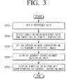
- FIG. 3 is a flowchart illustrating a method of controlling a host device according to an exemplary embodiment of the present general inventive concept.
- the remote controller 100 may set a reference axis to detect an angle in operation S310.
- the reference axis is an axis to form 0° in relation to a host device when the remote controller 100 detects an angle.
- the remote controller 100 may set a line connecting the host device to the remote controller 100 to be a reference axis.
- the remote controller 100 may set the direction of an end of the remote controller closest to or facing a host device 100 which is manipulated by a user to be a reference axis. For example, if a user presses a reference axis setting key (not shown) provided on the remote controller 100, the remote controller 100 sets the direction of the front end thereof to be a reference axis. If a reference axis is set when a user manipulates the remote controller 100, the user may set easily a desired reference axis.
- the remote controller 100 may use the Earth magnetic field sensor 213 to set a reference axis.
- the remote controller 100 detects an angle between the reference axis and the front end axis of the remote controller 100 in operation S320.
- the remote controller 100 detects a rotational angle with reference to the reference axis set using the above method.
- the remote controller 100 may detect a rotational angle using the angular velocity sensor 216 of the angle detection unit 210.
- the remote controller 100 is set in an operating mode corresponding to the currently detected angle in operation S330.
- the controlling unit 250 of the remote controller 100 receives the angle detected by the angle detection unit 210, and controls the remote controller 100 to operate in an operating mode corresponding to the current angle.
- the remote controller 100 displays the current operating mode on the display unit 230 in operation S340. For example, if the operating mode is a TV mode, the display unit 230 displays "TV.” If the operating mode is changed to a game console mode, the display unit 230 displays "GAME.”
- the remote controller 100 displays the function of the button unit 220 corresponding to the current operating mode on the display unit 230 in operation S350.
- the function of the button unit 220 changes according to the operating mode. Accordingly, the display unit 230 displays the function of the button unit 220, and thus a user can easily recognize the function currently provided by the button unit 220.
- a method of controlling a host device of the remote controller 100 may be provided.
- modes of the remote controller 100 depending on the angle of the remote controller 100 that is, a TV mode, a home theater mode, and a game console mode, will be explained with reference to FIGS. 4 to 6 .
- FIG. 4 is a view of a remote controller which is set to a TV mode according to an exemplary embodiment of the present general inventive concept.
- an external surface of the remote controller 100 may include a button unit 220 comprising a first sub-button unit 220a and a second sub-button unit 220b, a display unit 230, a first touch sensing unit 243, and a second touch sensing unit 246.
- a front end mark 410 and a rear end mark 420 are also displayed on the external surface of the remote controller 100.
- the perimeter of the remote controller 100 includes a front end 401, a rear end 402, a first side end 403 and a second side end 404.
- buttons unit 220, the display unit 230, the first touch sensing unit 243, and the second touch sensing unit 246 which are also found in FIG. 3 were discussed previously.
- the front end mark 410 corresponds to the front end of the remote controller 100
- the rear end mark 420 corresponds to the rear end of the remote controller 100. If the remote controller 100 is formed so that the front end is symmetrical to the rear end, such marks are displayed in order to distinguish the front end and the rear end.
- a front end axis 450 of the remote controller 100 represents a vertical axis of the front end.
- the front end axis 450 of the remote controller 100 is parallel to a reference axis 400. That is, the front end axis 450 may be perpendicular to a line that extends along the front end 401 of the remote controller 100.
- the angle between the reference axis 400 and the front end axis 450 of the remote controller 100 is 0°.
- TV is displayed on the display unit 230, the current operating mode is in a TV mode. That is, when the angle between the reference axis 400 and the front end axis 450 of the remote controller 100 is approximately 0°, the remote controller 100 is set to a TV mode, a host device to be controlled by the remote controller 100 is the TV 130.
- the button unit 220 including sub-button units 220a and 220b further include buttons to , and the functions of the buttons to are listed in order as “power,” “prev.ch,” “source,” “mute,” “vol up,” “vol down,” “ch up,” and “ch down.”
- the functions of the button unit 220 are used in a TV mode which is the operating mode shown in FIG. 4 , for example.
- the functions of the button unit 220 are also displayed on corresponding portions of the display unit 230.
- the remote controller 100 may be implemented to operate in a TV mode.
- FIG. 5 is a view illustrating a remote controller which is set to a home theater system (HTS) mode according to another exemplary embodiment of the present general inventive concept.
- a front end axis 500 of the remote controller 100 is placed in opposition to the reference axis 400.
- the angle between the reference axis 400 and the front end axis 500 of the remote controller 100 is approximately 180°.
- the display unit 230 displays "HTS" thereon, the operating mode is in a home theater mode. That is, if the angle between the reference axis 400 and the front end axis 500 of the remote controller 100 is approximately 180°, the remote controller 100 is set to a home theater mode, and a host device to be controlled by the remote controller 100 is the home theater 190.
- the button unit 220 includes buttons (1) to (8), and functions of the buttons (1) to (8)are listed in order as “ch down,” “ch up,” “vol down,” “vol up,” “pause,” “stop,” “play,” and “power.”
- the functions of the button unit 220 are used in a home theater mode which is a current operating mode.
- the functions of the button unit 220 are also displayed on corresponding portions of the display unit 230.
- the functions of the button unit 220 are changed from those of FIG. 4 . However, even if the functions of the button unit 220 are changed, the functions are displayed on the display unit 230. Therefore, a user can easily recognize the functions of the button unit 220.
- the remote controller 100 may touch the first touch sensing unit 243.
- the remote controller 100 may be implemented to operate in a home theater mode.
- FIG. 6 is a view illustrating a remote controller which is set to a game console mode according to another exemplary embodiment of the present general inventive concept.
- a front end axis 600 of the remote controller 100 is turned perpendicular to the reference axis 400.
- the angle between the reference axis 400 on a first side end 403 of the remote controller 100 and the front end axis 600 of the remote controller 100 is thus approximately 90°.
- the display unit 230 displays "GAME" thereon, the current operating mode is a game console mode. That is, if the angle between the reference axis 400 and the front end axis 600 of the remote controller 100 is approximately 90°, the remote controller 100 is set to a game console mode, and the host device to be controlled by the remote controller 100 is the game console 160.
- the button unit 220 includes buttons (1) to (8), and the functions of the buttons (1) to (8) are given in order as “A,” “B,” “C,” “D,” “up,” “down,” “left,” and “right.”
- the functions of the button unit 220 are used in a game console mode which is the current operating mode.
- the functions of the button unit 220 are also displayed on the corresponding portions of the display unit 230.
- the functions of the button unit 220 are changed in comparison with FIGS. 4 and 5 . However, even if the functions of the button unit 220 changes, the functions are displayed on the display unit 230. Therefore, a user can easily recognize the functions of the button unit 220.
- the remote controller 100 may grip the remote controller 100 using both hands.
- the user's hands may touch the first and second touch sensing units 243 and 246.
- the remote controller 100 may be implemented to operate in a game console mode.
- the operating mode of the remote controller 100 varies according to the angle of the remote controller 100.
- a user may change an operating mode by rotating the remote controller 100, and thus may more conveniently select a desired operating mode.
- the rotational angle is 0°, 90°, or 180°.
- operating modes corresponding to a predetermined range of angles may also be provided.
- an angle ranging from 0° to 45° corresponds to a TV mode
- an angle ranging from 45° to 135° corresponds to a game console mode
- an angle ranging from 135° to 180° corresponds to a home theater mode.
- the operating mode includes a TV mode, a home theater mode, and a game console mode in this exemplary embodiment of the preset general inventive concept, other operating modes may also be applied to the present general inventive concept.
- the present general inventive concept can also be embodied as computer-readable codes on a computer-readable medium.
- the computer-readable medium can include a computer-readable recording medium and a computer-readable transmission medium.
- the computer-readable recording medium is any data storage device that can store data as a program which can be thereafter read by a computer system. Examples of the computer-readable recording medium include read-only memory (ROM), random-access memory (RAM), CD-ROMs, magnetic tapes, floppy disks, and optical data storage devices.
- the computer-readable recording medium can also be distributed over network coupled computer systems so that the computer-readable code is stored and executed in a distributed fashion.
- the computer-readable transmission medium can transmit carrier waves or signals (e.g., wired or wireless data transmission through the Internet). Also, functional programs, codes, and code segments to accomplish the present general inventive concept can be easily construed by programmers skilled in the art to which the present general inventive concept pertains.
- the exemplary embodiment of the present general inventive concept may also be applied to any portable apparatus which includes a plurality of operating modes other than the above operating modes.
- portable apparatuses may include a portable media player (PMP), an MPEG layer 3 (MP3) player, a mobile phone, and a personal digital assistant (PDA).
- PMP portable media player
- MP3 MPEG layer 3
- PDA personal digital assistant
- this exemplary embodiment of the present general inventive concept may be applied to an MP3 player.
- the MP3 player may operate in a music mode
- the MP3 player may operate in a moving picture mode
- the MP3 player may operate in game console mode.
- a remote controller and a method of setting an operating mode thereof are provided, in which an angle between different axes is detected by the controller, and the remote controller operates in an operating mode corresponding to the detected angle.
- the remote controller operates in an operating mode corresponding to the detected angle.
- buttons of the remote controller vary according to the operating modes, and thus a user can use various functions using a small number of buttons.
- the functions of the buttons are displayed on a display, so a user can easily recognize the functions of the buttons.
Landscapes
- Engineering & Computer Science (AREA)
- Computer Networks & Wireless Communication (AREA)
- Physics & Mathematics (AREA)
- General Physics & Mathematics (AREA)
- Selective Calling Equipment (AREA)
Applications Claiming Priority (1)
| Application Number | Priority Date | Filing Date | Title |
|---|---|---|---|
| KR1020080063444A KR20100003512A (ko) | 2008-07-01 | 2008-07-01 | 각도를 이용하여 작동모드를 설정하는 원격제어장치, 및이를 적용한 작동모드 설정방법 및 호스트 기기 결정방법 |
Publications (2)
| Publication Number | Publication Date |
|---|---|
| EP2141675A2 true EP2141675A2 (fr) | 2010-01-06 |
| EP2141675A3 EP2141675A3 (fr) | 2011-08-03 |
Family
ID=41226124
Family Applications (1)
| Application Number | Title | Priority Date | Filing Date |
|---|---|---|---|
| EP09154986A Withdrawn EP2141675A3 (fr) | 2008-07-01 | 2009-03-12 | Contrôleur à distance pour configurer le mode de fonctionnement en utilisant des angles, procédé de configuration du mode de fonctionnement de celui-ci et procédé de détermination du dispositif hôte |
Country Status (3)
| Country | Link |
|---|---|
| US (1) | US8217825B2 (fr) |
| EP (1) | EP2141675A3 (fr) |
| KR (1) | KR20100003512A (fr) |
Cited By (2)
| Publication number | Priority date | Publication date | Assignee | Title |
|---|---|---|---|---|
| EP2557548A3 (fr) * | 2011-08-12 | 2013-05-22 | Medion AG | Dispositif d'entrée de commande à distance d'equipement électronique |
| EP2472489A3 (fr) * | 2010-12-31 | 2013-09-25 | Samsung Electronics Co., Ltd. | Dispositif de commande, récepteur de diffusion, procédé pour commander un récepteur de diffusion et procédé de fourniture de service |
Families Citing this family (21)
| Publication number | Priority date | Publication date | Assignee | Title |
|---|---|---|---|---|
| JP5178298B2 (ja) * | 2008-04-17 | 2013-04-10 | 三菱電機株式会社 | 表示装置用回動台およびその制御方法 |
| US20100164745A1 (en) * | 2008-12-29 | 2010-07-01 | Microsoft Corporation | Remote control device with multiple active surfaces |
| JP4816748B2 (ja) * | 2009-03-06 | 2011-11-16 | ソニー株式会社 | ナビゲーション装置及びナビゲーション方法 |
| US8963694B2 (en) * | 2010-12-17 | 2015-02-24 | Sony Corporation | System and method for remote controlled device selection based on device position data and orientation data of a user |
| KR101807622B1 (ko) * | 2010-12-27 | 2017-12-11 | 삼성전자주식회사 | 디스플레이 장치, 리모콘 및 이에 적용되는 제어방법 |
| US8698745B2 (en) * | 2011-05-20 | 2014-04-15 | Echostar Technologies L.L.C. | Configuring the functionality of control elements of a control device based on orientation |
| JP2013021378A (ja) * | 2011-06-17 | 2013-01-31 | Sony Corp | 制御装置、制御方法、プログラム、入力信号受信装置、操作入力装置、及び入力システム |
| KR101352329B1 (ko) * | 2011-11-23 | 2014-01-22 | 도시바삼성스토리지테크놀러지코리아 주식회사 | 리모트 컨트롤러를 이용하여 사용자 인터페이스를 제공하는 장치 및 방법 |
| WO2014021605A1 (fr) * | 2012-07-31 | 2014-02-06 | 인텔렉추얼디스커버리 주식회사 | Procédé et dispositif de commande à distance |
| KR101413992B1 (ko) * | 2012-11-23 | 2014-07-04 | 전자부품연구원 | 사용자 입력 장치 및 이를 이용한 전자기기 제어 시스템 |
| WO2015029231A1 (fr) * | 2013-08-30 | 2015-03-05 | 日立マクセル株式会社 | Dispositif terminal et procédé de commande à distance |
| KR101963325B1 (ko) * | 2013-09-23 | 2019-03-28 | 두산공작기계 주식회사 | 공작기계의 이송축 자동 선택이 가능한 포터블 엠피지 핸들러 및 이를 이용한 이송축 자동 선택 방법 |
| KR102220227B1 (ko) * | 2014-12-15 | 2021-02-25 | 삼성전자주식회사 | 음향 기기를 제어하는 디바이스 및 그 제어 방법 |
| CN104639964B (zh) * | 2015-02-13 | 2018-03-13 | 青岛海信电器股份有限公司 | 一种确定遥控器方向键键值的方法及装置 |
| JP6381774B2 (ja) * | 2015-02-24 | 2018-08-29 | 三菱電機株式会社 | リモートコントローラ、操作画面表示方法及びプログラム |
| CN104898829A (zh) * | 2015-04-17 | 2015-09-09 | 杭州豚鼠科技有限公司 | 体感交互系统 |
| WO2016181552A1 (fr) * | 2015-05-14 | 2016-11-17 | 日立マクセル株式会社 | Dispositif terminal et procédé de commande à distance |
| KR102626773B1 (ko) * | 2016-11-09 | 2024-01-19 | 삼성전자주식회사 | 디스플레이 장치 및 이의 제어 방법 |
| US10143921B1 (en) | 2017-06-02 | 2018-12-04 | Performance Designed Products Llc | Gaming peripheral with intelligent audio control |
| US10163336B1 (en) * | 2017-07-28 | 2018-12-25 | Dish Network L.L.C. | Universal remote control of devices based on orientation of remote |
| KR102329639B1 (ko) * | 2017-09-22 | 2021-11-22 | 삼성전자주식회사 | 원격 제어 장치 및 그 제어 방법 |
Family Cites Families (3)
| Publication number | Priority date | Publication date | Assignee | Title |
|---|---|---|---|---|
| WO1999016282A1 (fr) * | 1997-09-25 | 1999-04-01 | Mitsubishi Denki Kabushiki Kaisha | Telecommande |
| US7173604B2 (en) | 2004-03-23 | 2007-02-06 | Fujitsu Limited | Gesture identification of controlled devices |
| JP2007127993A (ja) * | 2005-11-07 | 2007-05-24 | Matsushita Electric Ind Co Ltd | 表示装置およびナビゲーション装置 |
-
2008
- 2008-07-01 KR KR1020080063444A patent/KR20100003512A/ko not_active Ceased
-
2009
- 2009-01-05 US US12/348,350 patent/US8217825B2/en active Active
- 2009-03-12 EP EP09154986A patent/EP2141675A3/fr not_active Withdrawn
Cited By (7)
| Publication number | Priority date | Publication date | Assignee | Title |
|---|---|---|---|---|
| EP2472489A3 (fr) * | 2010-12-31 | 2013-09-25 | Samsung Electronics Co., Ltd. | Dispositif de commande, récepteur de diffusion, procédé pour commander un récepteur de diffusion et procédé de fourniture de service |
| US9723350B2 (en) | 2010-12-31 | 2017-08-01 | Samsung Electronics Co., Ltd. | Control device, broadcast receiver, method for controlling broadcast receiver, and method for providing service |
| US10298990B2 (en) | 2010-12-31 | 2019-05-21 | Samsung Electronics Co., Ltd. | Control device, broadcast receiver, method for controlling broadcast receiver, and method for providing service |
| US11451851B2 (en) | 2010-12-31 | 2022-09-20 | Samsung Electronics Co., Ltd. | Control device, broadcast receiver, method for controlling broadcast receiver, and method for providing service |
| US12028570B2 (en) | 2010-12-31 | 2024-07-02 | Samsung Electronics Co., Ltd. | Control device, broadcast receiver, method for controlling broadcast receiver, and method for providing service |
| US12342028B2 (en) | 2010-12-31 | 2025-06-24 | Samsung Electronics Co., Ltd. | Control device, broadcast receiver, method for controlling broadcast receiver, and method for providing service |
| EP2557548A3 (fr) * | 2011-08-12 | 2013-05-22 | Medion AG | Dispositif d'entrée de commande à distance d'equipement électronique |
Also Published As
| Publication number | Publication date |
|---|---|
| KR20100003512A (ko) | 2010-01-11 |
| US20100001893A1 (en) | 2010-01-07 |
| EP2141675A3 (fr) | 2011-08-03 |
| US8217825B2 (en) | 2012-07-10 |
Similar Documents
| Publication | Publication Date | Title |
|---|---|---|
| US8217825B2 (en) | Remote controller to set operating mode using angles, method of setting operating mode thereof, and method of determining host device | |
| US8878775B2 (en) | Display device and control method thereof | |
| US20090051481A1 (en) | Remote controller for providing menu and method thereof | |
| JP5625506B2 (ja) | 操作端末装置、電子機器、および電子機器システム | |
| US9223416B2 (en) | Display apparatus, remote controlling apparatus and control method thereof | |
| EP2839355B1 (fr) | Procédé et dispositif de commande pour déplacement d'un objet virtuel et retour vers l'utilisateur | |
| US20050225453A1 (en) | Method and apparatus for controlling device using three-dimensional pointing | |
| US20040095317A1 (en) | Method and apparatus of universal remote pointing control for home entertainment system and computer | |
| EP2919481A1 (fr) | Dispositif de télécommande, dispositif d'affichage, et son procédé de commande | |
| EP1860528A2 (fr) | Dispositif de pointage, procédé et support de mouvement du pointeur, et dispositif d'affichage pour afficher le pointeur | |
| KR101784316B1 (ko) | 멀티 앵글 방송 서비스 제공 방법 및 이를 적용한 디스플레이 장치, 모바일 기기 | |
| CN101290554A (zh) | 提供图形用户界面的方法及其电子装置 | |
| US8699947B2 (en) | Method for determining the relative position of devices | |
| CN103003777B (zh) | 手持装置的向前指点方向的确定 | |
| JP4690376B2 (ja) | 遠隔操作装置、遠隔操作システム及び電気機器 | |
| TW200912699A (en) | Display device with navigation capability | |
| US20120117249A1 (en) | Mobile device and control method thereof | |
| CN104137556A (zh) | 使用控制装置的电子装置的控制方法和设备 | |
| WO2000026892A9 (fr) | Procede et appareil permettant de commander l'affichage d'un pointeur en fonction de la manipulation d'un dispositif de pointage | |
| CN204945943U (zh) | 用于为外部显示设备提供远程控制信号的远程控制设备 | |
| JP2006279424A (ja) | 電気機器遠隔操作システム | |
| JP2008027121A (ja) | 遠隔制御装置 | |
| US8593262B2 (en) | Motion-activated remote control backlight | |
| JPH07160411A (ja) | 入力装置 | |
| KR101611200B1 (ko) | 게임 조작키가 구비된 가전기기 겸용 멀티 리모콘 |
Legal Events
| Date | Code | Title | Description |
|---|---|---|---|
| PUAI | Public reference made under article 153(3) epc to a published international application that has entered the european phase |
Free format text: ORIGINAL CODE: 0009012 |
|
| AK | Designated contracting states |
Kind code of ref document: A2 Designated state(s): AT BE BG CH CY CZ DE DK EE ES FI FR GB GR HR HU IE IS IT LI LT LU LV MC MK MT NL NO PL PT RO SE SI SK TR |
|
| AX | Request for extension of the european patent |
Extension state: AL BA RS |
|
| PUAL | Search report despatched |
Free format text: ORIGINAL CODE: 0009013 |
|
| AK | Designated contracting states |
Kind code of ref document: A3 Designated state(s): AT BE BG CH CY CZ DE DK EE ES FI FR GB GR HR HU IE IS IT LI LT LU LV MC MK MT NL NO PL PT RO SE SI SK TR |
|
| AX | Request for extension of the european patent |
Extension state: AL BA RS |
|
| RIC1 | Information provided on ipc code assigned before grant |
Ipc: G08C 17/02 20060101AFI20110627BHEP |
|
| 17P | Request for examination filed |
Effective date: 20120202 |
|
| AKX | Designation fees paid |
Designated state(s): DE GB IT NL |
|
| RAP1 | Party data changed (applicant data changed or rights of an application transferred) |
Owner name: SAMSUNG ELECTRONICS CO., LTD. |
|
| STAA | Information on the status of an ep patent application or granted ep patent |
Free format text: STATUS: THE APPLICATION IS DEEMED TO BE WITHDRAWN |
|
| 18D | Application deemed to be withdrawn |
Effective date: 20161001 |