EP2141685A2 - Bildsignalverarbeitungsvorrichtung, Bildsignalverarbeitungsverfahren, Computerprogramm und Anzeigevorrichtung - Google Patents
Bildsignalverarbeitungsvorrichtung, Bildsignalverarbeitungsverfahren, Computerprogramm und Anzeigevorrichtung Download PDFInfo
- Publication number
- EP2141685A2 EP2141685A2 EP09164528A EP09164528A EP2141685A2 EP 2141685 A2 EP2141685 A2 EP 2141685A2 EP 09164528 A EP09164528 A EP 09164528A EP 09164528 A EP09164528 A EP 09164528A EP 2141685 A2 EP2141685 A2 EP 2141685A2
- Authority
- EP
- European Patent Office
- Prior art keywords
- image signal
- light emission
- correlation
- signal
- gain
- Prior art date
- Legal status (The legal status is an assumption and is not a legal conclusion. Google has not performed a legal analysis and makes no representation as to the accuracy of the status listed.)
- Withdrawn
Links
Images




Classifications
-
- G—PHYSICS
- G09—EDUCATION; CRYPTOGRAPHY; DISPLAY; ADVERTISING; SEALS
- G09G—ARRANGEMENTS OR CIRCUITS FOR CONTROL OF INDICATING DEVICES USING STATIC MEANS TO PRESENT VARIABLE INFORMATION
- G09G3/00—Control arrangements or circuits, of interest only in connection with visual indicators other than cathode-ray tubes
- G09G3/20—Control arrangements or circuits, of interest only in connection with visual indicators other than cathode-ray tubes for presentation of an assembly of a number of characters, e.g. a page, by composing the assembly by combination of individual elements arranged in a matrix no fixed position being assigned to or needed to be assigned to the individual characters or partial characters
- G09G3/2007—Display of intermediate tones
- G09G3/2077—Display of intermediate tones by a combination of two or more gradation control methods
- G09G3/2081—Display of intermediate tones by a combination of two or more gradation control methods with combination of amplitude modulation and time modulation
-
- G—PHYSICS
- G09—EDUCATION; CRYPTOGRAPHY; DISPLAY; ADVERTISING; SEALS
- G09G—ARRANGEMENTS OR CIRCUITS FOR CONTROL OF INDICATING DEVICES USING STATIC MEANS TO PRESENT VARIABLE INFORMATION
- G09G3/00—Control arrangements or circuits, of interest only in connection with visual indicators other than cathode-ray tubes
- G09G3/20—Control arrangements or circuits, of interest only in connection with visual indicators other than cathode-ray tubes for presentation of an assembly of a number of characters, e.g. a page, by composing the assembly by combination of individual elements arranged in a matrix no fixed position being assigned to or needed to be assigned to the individual characters or partial characters
-
- G—PHYSICS
- G09—EDUCATION; CRYPTOGRAPHY; DISPLAY; ADVERTISING; SEALS
- G09G—ARRANGEMENTS OR CIRCUITS FOR CONTROL OF INDICATING DEVICES USING STATIC MEANS TO PRESENT VARIABLE INFORMATION
- G09G3/00—Control arrangements or circuits, of interest only in connection with visual indicators other than cathode-ray tubes
- G09G3/20—Control arrangements or circuits, of interest only in connection with visual indicators other than cathode-ray tubes for presentation of an assembly of a number of characters, e.g. a page, by composing the assembly by combination of individual elements arranged in a matrix no fixed position being assigned to or needed to be assigned to the individual characters or partial characters
- G09G3/22—Control arrangements or circuits, of interest only in connection with visual indicators other than cathode-ray tubes for presentation of an assembly of a number of characters, e.g. a page, by composing the assembly by combination of individual elements arranged in a matrix no fixed position being assigned to or needed to be assigned to the individual characters or partial characters using controlled light sources
- G09G3/30—Control arrangements or circuits, of interest only in connection with visual indicators other than cathode-ray tubes for presentation of an assembly of a number of characters, e.g. a page, by composing the assembly by combination of individual elements arranged in a matrix no fixed position being assigned to or needed to be assigned to the individual characters or partial characters using controlled light sources using electroluminescent panels
-
- G—PHYSICS
- G09—EDUCATION; CRYPTOGRAPHY; DISPLAY; ADVERTISING; SEALS
- G09G—ARRANGEMENTS OR CIRCUITS FOR CONTROL OF INDICATING DEVICES USING STATIC MEANS TO PRESENT VARIABLE INFORMATION
- G09G3/00—Control arrangements or circuits, of interest only in connection with visual indicators other than cathode-ray tubes
- G09G3/20—Control arrangements or circuits, of interest only in connection with visual indicators other than cathode-ray tubes for presentation of an assembly of a number of characters, e.g. a page, by composing the assembly by combination of individual elements arranged in a matrix no fixed position being assigned to or needed to be assigned to the individual characters or partial characters
- G09G3/22—Control arrangements or circuits, of interest only in connection with visual indicators other than cathode-ray tubes for presentation of an assembly of a number of characters, e.g. a page, by composing the assembly by combination of individual elements arranged in a matrix no fixed position being assigned to or needed to be assigned to the individual characters or partial characters using controlled light sources
- G09G3/30—Control arrangements or circuits, of interest only in connection with visual indicators other than cathode-ray tubes for presentation of an assembly of a number of characters, e.g. a page, by composing the assembly by combination of individual elements arranged in a matrix no fixed position being assigned to or needed to be assigned to the individual characters or partial characters using controlled light sources using electroluminescent panels
- G09G3/32—Control arrangements or circuits, of interest only in connection with visual indicators other than cathode-ray tubes for presentation of an assembly of a number of characters, e.g. a page, by composing the assembly by combination of individual elements arranged in a matrix no fixed position being assigned to or needed to be assigned to the individual characters or partial characters using controlled light sources using electroluminescent panels semiconductive, e.g. using light-emitting diodes [LED]
- G09G3/3208—Control arrangements or circuits, of interest only in connection with visual indicators other than cathode-ray tubes for presentation of an assembly of a number of characters, e.g. a page, by composing the assembly by combination of individual elements arranged in a matrix no fixed position being assigned to or needed to be assigned to the individual characters or partial characters using controlled light sources using electroluminescent panels semiconductive, e.g. using light-emitting diodes [LED] organic, e.g. using organic light-emitting diodes [OLED]
- G09G3/3225—Control arrangements or circuits, of interest only in connection with visual indicators other than cathode-ray tubes for presentation of an assembly of a number of characters, e.g. a page, by composing the assembly by combination of individual elements arranged in a matrix no fixed position being assigned to or needed to be assigned to the individual characters or partial characters using controlled light sources using electroluminescent panels semiconductive, e.g. using light-emitting diodes [LED] organic, e.g. using organic light-emitting diodes [OLED] using an active matrix
- G09G3/3233—Control arrangements or circuits, of interest only in connection with visual indicators other than cathode-ray tubes for presentation of an assembly of a number of characters, e.g. a page, by composing the assembly by combination of individual elements arranged in a matrix no fixed position being assigned to or needed to be assigned to the individual characters or partial characters using controlled light sources using electroluminescent panels semiconductive, e.g. using light-emitting diodes [LED] organic, e.g. using organic light-emitting diodes [OLED] using an active matrix with pixel circuitry controlling the current through the light-emitting element
-
- G—PHYSICS
- G09—EDUCATION; CRYPTOGRAPHY; DISPLAY; ADVERTISING; SEALS
- G09G—ARRANGEMENTS OR CIRCUITS FOR CONTROL OF INDICATING DEVICES USING STATIC MEANS TO PRESENT VARIABLE INFORMATION
- G09G3/00—Control arrangements or circuits, of interest only in connection with visual indicators other than cathode-ray tubes
- G09G3/20—Control arrangements or circuits, of interest only in connection with visual indicators other than cathode-ray tubes for presentation of an assembly of a number of characters, e.g. a page, by composing the assembly by combination of individual elements arranged in a matrix no fixed position being assigned to or needed to be assigned to the individual characters or partial characters
- G09G3/22—Control arrangements or circuits, of interest only in connection with visual indicators other than cathode-ray tubes for presentation of an assembly of a number of characters, e.g. a page, by composing the assembly by combination of individual elements arranged in a matrix no fixed position being assigned to or needed to be assigned to the individual characters or partial characters using controlled light sources
- G09G3/30—Control arrangements or circuits, of interest only in connection with visual indicators other than cathode-ray tubes for presentation of an assembly of a number of characters, e.g. a page, by composing the assembly by combination of individual elements arranged in a matrix no fixed position being assigned to or needed to be assigned to the individual characters or partial characters using controlled light sources using electroluminescent panels
- G09G3/32—Control arrangements or circuits, of interest only in connection with visual indicators other than cathode-ray tubes for presentation of an assembly of a number of characters, e.g. a page, by composing the assembly by combination of individual elements arranged in a matrix no fixed position being assigned to or needed to be assigned to the individual characters or partial characters using controlled light sources using electroluminescent panels semiconductive, e.g. using light-emitting diodes [LED]
- G09G3/3208—Control arrangements or circuits, of interest only in connection with visual indicators other than cathode-ray tubes for presentation of an assembly of a number of characters, e.g. a page, by composing the assembly by combination of individual elements arranged in a matrix no fixed position being assigned to or needed to be assigned to the individual characters or partial characters using controlled light sources using electroluminescent panels semiconductive, e.g. using light-emitting diodes [LED] organic, e.g. using organic light-emitting diodes [OLED]
- G09G3/3225—Control arrangements or circuits, of interest only in connection with visual indicators other than cathode-ray tubes for presentation of an assembly of a number of characters, e.g. a page, by composing the assembly by combination of individual elements arranged in a matrix no fixed position being assigned to or needed to be assigned to the individual characters or partial characters using controlled light sources using electroluminescent panels semiconductive, e.g. using light-emitting diodes [LED] organic, e.g. using organic light-emitting diodes [OLED] using an active matrix
- G09G3/3258—Control arrangements or circuits, of interest only in connection with visual indicators other than cathode-ray tubes for presentation of an assembly of a number of characters, e.g. a page, by composing the assembly by combination of individual elements arranged in a matrix no fixed position being assigned to or needed to be assigned to the individual characters or partial characters using controlled light sources using electroluminescent panels semiconductive, e.g. using light-emitting diodes [LED] organic, e.g. using organic light-emitting diodes [OLED] using an active matrix with pixel circuitry controlling the voltage across the light-emitting element
-
- G—PHYSICS
- G09—EDUCATION; CRYPTOGRAPHY; DISPLAY; ADVERTISING; SEALS
- G09G—ARRANGEMENTS OR CIRCUITS FOR CONTROL OF INDICATING DEVICES USING STATIC MEANS TO PRESENT VARIABLE INFORMATION
- G09G3/00—Control arrangements or circuits, of interest only in connection with visual indicators other than cathode-ray tubes
- G09G3/20—Control arrangements or circuits, of interest only in connection with visual indicators other than cathode-ray tubes for presentation of an assembly of a number of characters, e.g. a page, by composing the assembly by combination of individual elements arranged in a matrix no fixed position being assigned to or needed to be assigned to the individual characters or partial characters
- G09G3/34—Control arrangements or circuits, of interest only in connection with visual indicators other than cathode-ray tubes for presentation of an assembly of a number of characters, e.g. a page, by composing the assembly by combination of individual elements arranged in a matrix no fixed position being assigned to or needed to be assigned to the individual characters or partial characters by control of light from an independent source
- G09G3/36—Control arrangements or circuits, of interest only in connection with visual indicators other than cathode-ray tubes for presentation of an assembly of a number of characters, e.g. a page, by composing the assembly by combination of individual elements arranged in a matrix no fixed position being assigned to or needed to be assigned to the individual characters or partial characters by control of light from an independent source using liquid crystals
-
- G—PHYSICS
- G09—EDUCATION; CRYPTOGRAPHY; DISPLAY; ADVERTISING; SEALS
- G09G—ARRANGEMENTS OR CIRCUITS FOR CONTROL OF INDICATING DEVICES USING STATIC MEANS TO PRESENT VARIABLE INFORMATION
- G09G2300/00—Aspects of the constitution of display devices
- G09G2300/08—Active matrix structure, i.e. with use of active elements, inclusive of non-linear two terminal elements, in the pixels together with light emitting or modulating elements
- G09G2300/0809—Several active elements per pixel in active matrix panels
- G09G2300/0842—Several active elements per pixel in active matrix panels forming a memory circuit, e.g. a dynamic memory with one capacitor
- G09G2300/0861—Several active elements per pixel in active matrix panels forming a memory circuit, e.g. a dynamic memory with one capacitor with additional control of the display period without amending the charge stored in a pixel memory, e.g. by means of additional select electrodes
- G09G2300/0866—Several active elements per pixel in active matrix panels forming a memory circuit, e.g. a dynamic memory with one capacitor with additional control of the display period without amending the charge stored in a pixel memory, e.g. by means of additional select electrodes by means of changes in the pixel supply voltage
-
- G—PHYSICS
- G09—EDUCATION; CRYPTOGRAPHY; DISPLAY; ADVERTISING; SEALS
- G09G—ARRANGEMENTS OR CIRCUITS FOR CONTROL OF INDICATING DEVICES USING STATIC MEANS TO PRESENT VARIABLE INFORMATION
- G09G2320/00—Control of display operating conditions
- G09G2320/02—Improving the quality of display appearance
- G09G2320/0247—Flicker reduction other than flicker reduction circuits used for single beam cathode-ray tubes
-
- G—PHYSICS
- G09—EDUCATION; CRYPTOGRAPHY; DISPLAY; ADVERTISING; SEALS
- G09G—ARRANGEMENTS OR CIRCUITS FOR CONTROL OF INDICATING DEVICES USING STATIC MEANS TO PRESENT VARIABLE INFORMATION
- G09G2320/00—Control of display operating conditions
- G09G2320/02—Improving the quality of display appearance
- G09G2320/0261—Improving the quality of display appearance in the context of movement of objects on the screen or movement of the observer relative to the screen
-
- G—PHYSICS
- G09—EDUCATION; CRYPTOGRAPHY; DISPLAY; ADVERTISING; SEALS
- G09G—ARRANGEMENTS OR CIRCUITS FOR CONTROL OF INDICATING DEVICES USING STATIC MEANS TO PRESENT VARIABLE INFORMATION
- G09G2320/00—Control of display operating conditions
- G09G2320/10—Special adaptations of display systems for operation with variable images
- G09G2320/103—Detection of image changes, e.g. determination of an index representative of the image change
Definitions
- Apparatuses and methods consistent with the present invention relate to an image signal processing apparatus, an image signal processing method, a computer program, and a display device.
- an organic electroluminescence (EL) display device also referred to as an organic light-emitting diode (OLED) display device
- a field emission display (FED) device a field emission display (FED) device
- LCD liquid crystal display
- PDP plasma display panel
- Light emission of the display devices is mainly divided into an impulse type and a hold type.
- the CRT display device and the FED device display an image by using the impulse type light emission
- the LCD device displays an image by using the hold type light emission to continuously emit light for one frame period.
- a display device using the impulse type light emission has a display characteristic different from that of a display device using the hold type light emission.
- the display device using the impulse type light emission emits light intermittently, has a moving image characteristic, and thus a phenomenon of creating a residual image of a previous frame, which is called as a motion residual image (a viewer does not experience motion residual images), rarely occurs.
- the display device using the impulse type light emission easily flickers.
- the display device using the hold type light emission continuously displays the same image for one frame period and rarely flickers, however easily creates motion residual images.
- Japanese Patent Publication No. 2006-330664 discloses a technology for suppressing flickers by emitting light twice in one frame period
- Japanese Patent Publication No. 2006-317894 discloses a technology for suppressing flickers by emitting light from every two scan lines in one frame period
- Japanese Patent Publication No. 2006-165974 discloses a technology for suppressing double images by generating an interpolation frame during when a moving image is displayed.
- FIGS. 9A and 9B are images for describing a problem of a display device using a flicker suppressing method in the related art.
- FIG. 9A illustrates a case when the display device displays a letter X on a screen as a still image
- FIG. 9B illustrates a case when the display device displays the letter X on the screen as a moving image.
- the display device using the flicker suppressing method in the related art may not improve image quality sufficiently.
- a motion residual image easily occurs.
- a method similar to a double image suppressing method in the related art is used to suppress the motion residual image.
- the motion residual image is suppressed by emitting light twice in one frame period and interpolating a frame corresponding to the second light emission from previous and current frames.
- the motion residual image suppressing technology in the display device using the hold type light emission method in the related art may fail to form an interpolation frame due to the difficulty of forming the interpolation frame.
- the motion residual image suppressing technology in the display device using the hold type light emission method in the related art which prevents the motion residual image by forming the interpolation frame, may not improve image quality sufficiently.
- Embodiments of the present invention provide a new and improved image signal processing apparatus, an image signal processing method, a computer program, and a display device, which may improve image quality by determining a correlation between current and previous frames based on an input image signal and controlling a gain of the image signal and a light emission time based on the determined correlation.
- an image signal processing apparatus including a correlation determination unit which determines a correlation between a current frame, which represents an input image signal, and a previous frame in each of a plurality of pixels, and outputs a correlation signal of a signal level according to a determination result; a light emission time setting unit which outputs a light emission time control signal that defines a light emission time in one frame period, based on the correlation signal; an adjustment value setting unit which outputs an adjustment value that adjusts a gain of the image signal, based on the correlation signal; and a gain adjustment unit which adjusts the gain of the image signal based on the adjustment value and outputs the image signal of which the gain is adjusted, wherein the light emission intensity in one frame period, which is defined by a product of a light emission time corresponding to the light emission time control signal and a signal level corresponding to the image signal output from the gain adjustment unit, is uniform regardless of the determination result of the correlation determination unit.
- image quality may preferably be improved by determining a correlation between current and previous frames based on an input image signal and controlling a gain of the image signal and a light emission time based on the determined correlation.
- the correlation determination unit may preferably include a frame memory which stores the input image signal in one frame period; and a comparison unit which compares an image signal corresponding to the current frame to an image signal corresponding to the previous frame output from the frame memory, in each of the pixels, and outputs the correlation signal according to a comparison result.
- a correlation between current and previous frames may preferably be determined and a correlation signal of a signal level according to a determination result may be output.
- image quality may be improved by determining a correlation between current and previous frames based on an input image signal and controlling a gain of the image signal and a light emission time based on the determined correlation.
- an image signal processing method including determining a correlation between a current frame, which represents an input image signal, and a previous frames, in each of a plurality of pixels, and outputting a correlation signal of a signal level according to a determination result; outputting a light emission time control signal that defines a light emission time in one frame period, based on the correlation signal; outputting an adjustment value that adjusts a gain of the image signal, based on the correlation signal; and adjusting the gain of the image signal based on the adjustment value and outputting the image signal of which the gain is adjusted.
- image quality may preferably be improved by determining a correlation between current and previous frames based on an input image signal, and controlling a gain of the image signal and a light emission time based on the determined correlation.
- a computer-readable medium encoded with a computer program for causing a computer to execute an image signal processing method including determining a correlation between a current frame, which represents an input image signal, and a previous frame, in each of a plurality of pixels, and outputting a correlation signal of a signal level according to a determination result; outputting a light emission time control signal that defines a light emission time in one frame period, based on the correlation signal; outputting an adjustment value that adjusts a gain of the image signal, based on the correlation signal; and adjusting the gain of the image signal based on the adjustment value and outputting the image signal of which the gain is adjusted.
- image quality may preferably be improved by determining a correlation between current and previous frames based on an input image signal and controlling a gain of the image signal and a light emission time based on the determined correlation.
- examples of computer-readable media include magnetic media such as hard disks, floppy disks, and magnetic tape; optical media such as CD ROM disks and DVD; magneto-optical media such as optical disks; and hardware devices that are specially configured to store and perform program instructions, such as read-only memory (ROM), random access memory (RAM), flash memory, and the like.
- magnetic media such as hard disks, floppy disks, and magnetic tape
- optical media such as CD ROM disks and DVD
- magneto-optical media such as optical disks
- hardware devices that are specially configured to store and perform program instructions, such as read-only memory (ROM), random access memory (RAM), flash memory, and the like.
- a display device including an image signal adjustment unit which adjusts a gain of an image signal and a light emission time in one frame period, based on an input image signal; and an image display unit having at least one pixel that includes a light emission element that emits light itself according to a current, and displays an image based on the image signal and a light emission time control signal that defines the light emission time, wherein the image signal and the light emission time control signal are output from the image signal adjustment unit, wherein the image signal adjustment unit includes a correlation determination unit which determines a correlation between a current, which represents an input image signal, and a previous frame, in each of a plurality of pixels, and outputs a correlation signal of a signal level according to a determination result; a light emission time setting unit which outputs the light emission time control signal based on the correlation signal; an adjustment value setting unit which outputs an adjustment value that adjusts the gain of the image signal, based on the correlation signal; and a gain adjustment unit which adjusts the gain of
- image quality may preferably be improved by determining a correlation between current and previous frames based on an input image signal and controlling a gain of the image signal and a light emission time based on the determined correlation.
- an image signal processing apparatus 100 Before describing an image signal processing apparatus according to an exemplary embodiment of the present invention (hereinafter referred to as an image signal processing apparatus 100 (see FIG. 3 )), an approach to control a gain of an image signal and a light emission time, according to an exemplary embodiment of the present invention, will now be described.
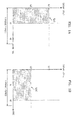
- FIGS. 1A and 1B are a first set of graphs for describing an approach to control a gain of an image signal and a light emission time, according to an exemplary embodiment of the present invention.
- FIGS. 2A through 2D are a second set of graphs for describing the control approach.
- FIG. 1A illustrates an impulse type light emission state.
- the signal level is L1
- the light emission time is t1
- the light emission intensity is L1 ⁇ t1.
- FIG. 1B illustrates a hold type light emission state.
- the signal level is L2 (L2 ⁇ L1)
- the light emission time is t2 (t2>t1)
- the light emission intensity is L2 ⁇ t2.
- Equation 1 If the correlation of Equation 1 is true, that is, if the light emission intensities are equal to each other, due to the integral effect for human eyes, the impulse type light emission state illustrated in FIG. 1A and the hold type light emission state illustrated in FIG. 1B are viewed as images having the same brightness. Thus, if the same light emission intensity is maintained, although the impulse type light emission state and the hold type light emission state switch one another, a gray scale is not affected and thus image quality does not deteriorate.
- FIGS. 1A and 1B it can be seen that a gray scale is not affected if the correlation of Equation 1 is true even when the impulse type light emission state ( FIG. 1A ) and the hold type light emission state ( FIG. 1B ) switch one another.
- the control approach is not limited to the two different states illustrated in FIGS. 1A and 1B .
- the image signal processing apparatus 100 may change the gain of the image signal and the light emission time into three or more states as illustrated in FIGS. 2A through 2D .
- FIG. 2A illustrates the impulse type light emission state illustrated in FIG. 1A
- FIG. 2D illustrates the hold type light emission state illustrated in FIG. 1B
- FIGS. 2B and 2C illustrate intermediate light emission states between the impulse type light emission state ( FIG. 1A ) and the hold type light emission state ( FIG. 1B ).
- the image signal processing apparatus 100 may realize various light emission states. Also, although a light emission state is changed as illustrated in FIGS. 2A through 2D , if the gain of the image signal and the light emission time are controlled to have the same light emission intensity in the different states as shown in Equation 2, the gray scale is not affected and thus the image quality does not deteriorate.
- the image signal processing apparatus 100 prevents flickers and motion residual images by controlling the gain of the image signal and the light emission time according to, for example, processing operations (1) through (3) to be described below.
- the image signal processing apparatus 100 determines a correlation between a frame on which an image represented by an input image signal is displayed (hereinafter referred to as a current frame) and a frame in one frame period before the current frame (hereinafter referred to as a previous frame). By determining the correlation between the current and previous frames, the image signal processing apparatus 100 may determine whether a subject (for example, a person, an animal, or an object such as a car) included in the image represented by the image signal is fixed or moves. Also, by determining a correlation strength between the current and previous frames (hereinafter referred to as a correlation level), the image signal processing apparatus 100 may further determine a degree of motion of the subject.
- a subject for example, a person, an animal, or an object such as a car
- the image signal processing apparatus 100 may display the image on a display screen in a light emission state corresponding to the correlation strength. For example, if the correlation level has a maximum value (i.e., if the correlation strength is the highest), the image has a high possibility of being a still image, and thus, the image signal processing apparatus 100 displays the image in the hold type light emission state illustrated in FIG. 2D . On the other hand, if the correlation level has a minimum value (i.e., if the correlation strength is the lowest), the image has a high possibility of being a moving image in which a subject greatly moves, and thus, the image signal processing apparatus 100 displays the image in the impulse type light emission state illustrated in FIG. 2A .
- the image signal processing apparatus 100 displays the image in the intermediate light emission state illustrated in FIG. 2B or FIG. 2C according to the correlation level.
- the image signal processing apparatus 100 may realize various light emission states. A method of controlling a light emission state according to a correlation level, according to an embodiment of the present invention, will be described later.
- the image signal processing apparatus 100 determines the correlation level in each pixel corresponding to a display location of the display screen on which the image is displayed.
- a method of obtaining a differential value (or an absolute value of the differential value) in each pixel between the image signal of the previous frame and the image signal of the current frame may be used as a correlation level determination method, however, the present invention is not limited thereto.
- the image signal processing apparatus 100 may detect a motion vector and derive the correlation level based on the size of the motion vector.
- the image signal processing apparatus 100 may divide the display screen into a plurality of separate regions and may determine the correlation level in each separate region. In this case, the image signal processing apparatus 100 determines the correlation level in each pixel included in a separate region and outputs the most frequent determination result as the determination result of the separate region.
- the correlation level determination method of the image signal processing apparatus 100 is not limited thereto.
- the image signal processing apparatus 100 Based on the correlation level determined in the processing operation (1), the image signal processing apparatus 100 outputs a correlation signal of a signal level according to the correlation level.
- the image signal processing apparatus 100 may uniquely output the correlation signal of the signal level according to the correlation level by using a look-up table in which the correlation level corresponds to the signal level of the correlation signal, however, the present invention is not limited thereto.
- the image signal processing apparatus 100 controls the gain of the image signal and the light emission time.
- the control of the gain of the image signal based on the correlation signal and the control of the light emission time based on the correlation signal will now be separately described.
- the image signal processing apparatus 100 may synchronously control the gain of the image signal and the light emission time.
- the image signal processing apparatus 100 Based on the correlation signal, the image signal processing apparatus 100 outputs an adjustment signal in each pixel according to the signal level of the correlation signal. Then, for example, the image signal processing apparatus 100 adjusts a gain of an input image signal by multiplying the input image signal by the adjustment signal.
- the adjustment signal functions as a multiplication coefficient for adjusting the gain of the image signal.
- the image signal processing apparatus 100 Based on the correlation signal, the image signal processing apparatus 100 outputs a light emission time control signal according to the signal level of the correlation signal.
- the light emission time control signal is a signal for defining the light emission time in one frame period. A light emission time control signal output method of the image signal processing apparatus 100 will be described later.
- the image signal processing apparatus 100 may adjust (control) the gain of the image signal and may control the light emission time by separately outputting the adjustment signal and the light emission time control signal based on the correlation signal.
- the image signal processing apparatus 100 selects, for example, hold type light emission. Then, the image signal processing apparatus 100 controls the gain of the image signal and the light emission time to obtain the hold type light emission state as illustrated in FIG. 2D .
- the image signal processing apparatus 100 prevents flickers by selecting the hold type light emission.
- the image signal processing apparatus 100 may prevent flickers and motion residual images.
- the phase alternating line (PAL) standard adopted in European counties uses a frame period of 50Hz lower than 59.94Hz, which is the frame period used in the national television standards committee (NTSC) standard, and thus flickers may be created more easily in the PAL standard.
- PAL phase alternating line
- NSC national television standards committee
- the image signal processing apparatus 100 may select the hold type light emission and thus may prevent flickers.
- the image signal processing apparatus 100 selects, for example, impulse type light emission. Then, the image signal processing apparatus 100 controls the gain of the image signal and the light emission time to obtain the impulse type light emission state illustrated in FIG. 2A .
- the image signal processing apparatus 100 prevents motion residual images by selecting the impulse type light emission.
- the image signal processing apparatus 100 may prevent flickers and motion residual images.
- the image signal processing apparatus 100 controls the gain of the image signal and the light emission time according to the signal level of the correlation signal. For example, if the correlation signal output in the processing operation (2) corresponds to an intermediate value closer to the maximum value of the correlation level, the image signal processing apparatus 100 controls the gain of the image signal and the light emission time to obtain the intermediate light emission state, as illustrated in FIG. 2C , and thus prevent flickers rather than motion residual images. Otherwise, if the correlation signal output in the processing operation (2) corresponds to an intermediate value closer to the minimum value of the correlation level, the image signal processing apparatus 100 controls the gain of the image signal and the light emission time to obtain the intermediate light emission state, as illustrated in FIG. 2B , and thus prevent motion residual images rather than flickers.
- the image signal processing apparatus 100 controls the gain of the image signal and the light emission time based on the correlation signal.
- the image signal processing apparatus 100 may realize various light emission states according to the signal level of the correlation signal (i.e., according to the correlation level).
- the image signal processing apparatus 100 may control a gain of an image signal and a light emission time based on a correlation between current and previous frames by performing, for example, the processing operations (1) through (3). Thus, the image signal processing apparatus 100 may prevent flickers and motion residual images.
- an organic electroluminescence (EL) display device which is a self-emission type display device for emitting light according to a current flowing in a light emission element included in the organic EL display device, will be representatively described as a display device for displaying an image signal output from the image signal processing apparatus 100, according to an exemplary embodiment of present invention (hereinafter referred to as a display device 200 (see FIG. 8 )).
- an organic EL element that is, a light emission element included in the organic EL display device, has a linear current-light emission intensity (IL) characteristic, and thus, light is emitted according to the current applied to the light emission element.
- IL current-light emission intensity
- the organic EL display device is used as the display device 200 for displaying the image signal output from the image signal processing apparatus 100, a linear correlation may be formed between the light intensity of a subject, which is represented by the image signal output from the image signal processing apparatus 100, and the light emission intensity of light emitted from the light emission element of the display device 200, and thus, an image may be displayed reliably for the image signal.
- the display device 200 for displaying the image signal output from the image signal processing apparatus 100 is not limited to the organic EL display device.
- the display device 200 for displaying the image signal output from the image signal processing apparatus 100 may be a display device such as a liquid crystal display (LCD) device, which may emit light according to a current or a voltage applied to a light emission element included in the LCD device.
- LCD liquid crystal display
- FIG. 3 is a block diagram of an image signal processing apparatus 100 according to an exemplary embodiment of the present invention.
- red (R), green (G), and blue (B) image signals may be independently input to the image signal processing apparatus 100.
- the image signal input to the image signal processing apparatus 100 is, for example, a digital signal to be used for digital broadcasting
- the image signal may also be, for example, an analog signal used for analog broadcasting.
- the image signal processing apparatus 100 may include, for example, an analog-to-digital (A/D) converter (not shown) in a front portion of the structure illustrated in FIG. 3 .
- the image signal input to the image signal processing apparatus 100 may be, for example, a signal transmitted from a broadcasting station and received by the image signal processing apparatus 100, however is not limited thereto.
- the image signal input to the image signal processing apparatus 100 may be a signal transmitted from an external device through a network such as a local area network (LAN) and received by the image signal processing apparatus 100, or may be an image file stored in a memory unit (not shown) included in the image signal processing apparatus 100 and read by the image signal processing apparatus 100.
- LAN local area network
- the image signal processing apparatus 100 includes a correlation determination unit 102 and a frame distribution unit 104.
- Signal processing in the correlation determination unit 102 and the frame distribution unit 104 may be performed by using, for example, hardware (e.g., a signal processing circuit) and/or software (signal processing software).
- the image signal processing apparatus 100 may include, for example, a control unit (not shown) such as a micro processing unit (MPU) for controlling the whole image signal processing apparatus 100, a read only memory (ROM) (not shown) for recording therein a computer program or control data, such as operation parameters, which is used by the control unit, a random access memory (RAM) (not shown) for primarily recording the computer program to be executed by the control unit, a reception unit (not shown) for receiving an image signal transmitted from, for example, a broadcasting station, a memory unit (not shown) for recording image files, a manipulation unit (not shown) to be manipulated by a user, and a communication unit (not shown) for communicating with an external device (not shown).
- the image signal processing apparatus 100 accesses each of the above components via, for example, a data transmission line such as a bus.
- the memory unit may be, for example, a magnetic recording medium such as a hard disk, nonvolatile memory such as electrically erasable and programmable read only memory (EEPROM), flash memory, magnetoresistive random access memory (MRAM), ferroelectric random access memory (FeRAM), or phase change random access memory (PRAM), or a magneto optical disk, however is not limited thereto.
- the manipulation unit may be, for example, a manipulation input device such as a keyboard or a mouse, buttons, direction keys, or a combination thereof, however is not limited thereto.
- the image signal processing apparatus 100 and the external device may be physically connected to each other, for example, by using a universal serial bus (USB) connection or according to the Institute of Electrical and Electronics Engineers (IEEE) 1394 standard, or may be wirelessly connected to each other, for example, by using a wireless universal serial bus (WUSB) connection or according to the IEEE 802.11 standard.
- the image signal processing apparatus 100 and the external device may be connected to each other, for example, through a network.
- the network may be, for example, a wired network such as a LAN or a wide area network (WAN), a wireless network such a wireless local area network (WLAN) using multiple-input multiple-output (MIMO) technology, or the Internet using a communication protocol such as a transmission control protocol/Internet protocol (TCP/IP), however is not limited thereto.
- a wired network such as a LAN or a wide area network (WAN)
- a wireless network such as a wireless local area network (WLAN) using multiple-input multiple-output (MIMO) technology
- MIMO multiple-input multiple-output
- TCP/IP transmission control protocol/Internet protocol
- the communication unit has an interface according to a connection method with the external device.
- the correlation determination unit 102 determines a correlation between current and previous frames in each pixel corresponding to a display location of a display screen on which an image is displayed. Then, the correlation determination unit 102 outputs a correlation signal of a signal level according to a determined correlation level. In more detail, the correlation determination unit 102 performs the processing operation by (1) determining the correlation between the current and previous frames, and (2) outputting the correlation signal of the signal level according to the determination result (correlation level).
- FIG. 4 is a block diagram of the correlation determination unit 102 illustrated in FIG. 3 .
- the correlation determination unit 102 includes a frame memory 120 and a comparison unit 122.
- the frame memory 120 stores an image signal in one frame period (i.e., an image for one screen). That is, the frame memory 120 may store the image signal corresponding to a previous frame.
- the comparison unit 122 determines a correlation level in each pixel corresponding to a display location of a display screen on which an image is displayed.
- the comparison unit 122 may obtain an absolute value of a differential value between the image signal of the previous frame and the image signal of the current frame in each pixel and may determine the correlation level according to the size of the absolute value of the differential value. For example, if the absolute value of the differential value in a pixel is zero, the possibility that images of previous and current frames in a pixel are the same (i.e., the possibility of being a still image) is high.
- the comparison unit 122 may determine whether an image represented by the input image signal is a still image or a moving image and may also determine the degree of motion of a subject in the image.
- the correlation level determination method of the comparison unit 122 is not limited thereto.
- the comparison unit 122 Based on the determined correlation level, the comparison unit 122 outputs a correlation signal of a signal level in each pixel according to the correlation level.
- the comparison unit 122 may correspondingly output the correlation signal of the signal level according to the correlation level by using, for example, a look-up table in which the correlation level corresponds to the signal level of the correlation signal, however, the present invention is not limited thereto.
- the look-up table may be stored in, for example, a memory unit included in the comparison unit 122.
- the memory unit included in the comparison unit 122 may be, for example, nonvolatile memory such as EEPROM or flash memory, however is not limited thereto.
- the comparison unit 122 may appropriately read the look-up table recorded in a memory unit (not shown) of the image signal processing apparatus 100.
- the correlation determination unit 102 may determine the correlation level and may output the correlation signal of the signal level in each pixel according to the determined correlation level.
- the frame distribution unit 104 controls a gain of an image signal and a light emission time. That is, the frame distribution unit 104 performs the processing operation (3) (i.e., the control of the gain of the image signal and the light emission time based on the correlation signal).
- the frame distribution unit 104 includes an adjustment value setting unit 110, a gain adjustment unit 112, and a light emission time setting unit 114.
- the adjustment value setting unit 110 and the gain adjustment unit 112 perform the processing operation (3-1) (i.e., the control of the gain of the image signal) and the light emission time setting unit 114 performs the processing operation (3-2) (i.e., the control of the light emission time).
- the adjustment value setting unit 110 Based on the correlation signal output from the correlation determination unit 102, the adjustment value setting unit 110 outputs an adjustment signal in each pixel according to a signal level of a correlation signal.
- FIG. 5 is a conceptual diagram of the adjustment value setting unit 110 illustrated in FIG. 3 , according to an exemplary embodiment of the present invention.
- the correlation determination unit 102 for outputting the correlation signal is also illustrated.
- the adjustment value setting unit 110 selectively outputs an adjustment value km (m is an integer equal to or greater than one) according to the signal level of the correlation signal.
- the adjustment value setting unit 110 includes a switch SW1 to be connected to a different value of a plurality of different values according to the correlation signal.
- the structure of the adjustment value setting unit 110 is not limited thereto.
- the adjustment value setting unit 110 may correspondingly output the adjustment value km according to the signal level of the correlation signal by using a look-up table in which the adjustment value km corresponds to the signal level of the correlation signal.
- the look-up table may be stored in, for example, a memory unit included in the adjustment value setting unit 110.
- the memory unit included in the adjustment value setting unit 110 may be, for example, nonvolatile memory such as EEPROM or flash memory, however is not limited thereto.
- the adjustment value setting unit 110 may appropriately read the look-up table stored in the memory unit of the image signal processing apparatus 100.
- the gain adjustment unit 112 adjusts the gain of the image signal.
- the gain adjustment unit 112 adjusts the gain of the image signal by, for example, multiplying the image signal by the adjustment value km received from the adjustment value setting unit 110.
- the gain adjustment unit 112 may be, for example, a multiplier, however is not limited thereto.
- the image signal processing apparatus 100 may control the gain of the image signal based on the correlation signal as described above in the processing operations (I) through (III).
- the light emission time setting unit 114 Based on the correlation signal output from the correlation determination unit 102, the light emission time setting unit 114 outputs a light emission time control signal according to the signal level of the correlation signal.
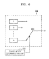
- FIG. 6 is a conceptual diagram of the light emission time setting unit 114 illustrated in FIG. 3 , according to an exemplary embodiment of the present invention.
- the correlation determination unit 102 for outputting the correlation signal is also illustrated.
- the light emission time setting unit 114 Based on the correlation signal output from the correlation determination unit 102, the light emission time setting unit 114 selectively outputs a light emission time control signal jn (n is an integer equal to or greater than one) according to the signal level of the correlation signal.
- the light emission time setting unit 114 includes a switch SW2 to be connected to a different signal of a plurality of signals according to the correlation signal.
- the structure of the light emission time setting unit 114 is not limited thereto.
- the light emission time setting unit 114 may uniquely output the light emission time control signal jn according to the signal level of the correlation signal by using a look-up table in which a signal level of the light emission time control signal jn corresponds to the signal level of the correlation signal.
- the look-up table may be stored in, for example, a memory unit included in the light emission time setting unit 114.
- the present invention is not limited thereto.
- the image signal processing apparatus 100 may control the light emission time based on the correlation signal as described above in the processing operations (I) through (III).
- the image signal processing apparatus 100 performs the processing operation (1) (i.e., the determination of the correlation between the current and previous frames), the output operation (2) (i.e., the output of correlation signal of signal level according to determination result), and the processing operation (3) (i.e., the control of the gain of the image signal and the light emission time based on the correlation signal). Accordingly, the image signal processing apparatus 100 may prevent flickers and motion residual images and may improve image quality.
- the processing operation (1) i.e., the determination of the correlation between the current and previous frames
- the output operation (2) i.e., the output of correlation signal of signal level according to determination result
- the processing operation (3) i.e., the control of the gain of the image signal and the light emission time based on the correlation signal. Accordingly, the image signal processing apparatus 100 may prevent flickers and motion residual images and may improve image quality.
- the image signal processing apparatus 100 determines a correlation between current and previous frames based on an input image signal, and controls a gain of an image signal and a light emission time based on the determined correlation.
- the image signal processing apparatus 100 controls a gain of an input image signal by using an adjustment value based on a correlation signal according to a determined correlation level.
- the image signal processing apparatus 100 controls the light emission time in one frame period by outputting a light emission time control signal based on the correlation signal according to the determined correlation level.
- the image signal processing apparatus 100 controls the adjustment value and the light emission time control signal based on the correlation signal so that the light emission intensity in one frame period satisfies a correlation represented in Equation 2.
- the image signal processing apparatus 100 may realize, for example, various light emission states described above in the processing operations (I) through (III) and thus may prevent flickers and motion residual images. Accordingly, the image signal processing apparatus 100 may improve image quality by determining a correlation between current and previous frames based on an input image signal and controlling a gain of the image signal and a light emission time based on the determined correlation.
- the image signal processing apparatus 100 is described as an embodiment of the present invention, the present invention is not limited thereto.
- the image signal processing apparatus 100 of the present invention may be applied to, for example, a display device such as an organic EL display device or an LCD device, which includes a light emission element for emitting light according to a current or a voltage, a computer such as a personal computer (PC) or a server, or a portable communication device such as a mobile phone.
- the image signal processing apparatus 100 may be realized as, for example, an integrated circuit (IC) chip on which the components illustrated in FIG. 3 are integrated. A case when the image signal processing apparatus 100 of the present invention is applied to a display device will be described later.
- IC integrated circuit
- a computer program encoded on a computer-readable medium and for allowing a computer to function as the image signal processing apparatus 100 may improve image quality by determining a correlation between current and previous frames based on an input image signal, and controlling a gain of the image signal and a light emission time based on the determined correlation.
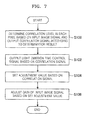
- FIG. 7 is a flowchart of an image signal processing method according to an embodiment of the present invention.
- the image signal processing method is performed by the image signal processing apparatus 100.
- the image signal processing method may also be applied to the display device 200, as will be described later.
- FIG. 7 will be described in conjunction with FIGS. 3 through 6 .
- the image signal processing apparatus 100 determines a correlation level between current and previous frames in each pixel based on an input image signal, and outputs a correlation signal according to a determination result (the correlation level) (operation S100).
- the image signal processing apparatus 100 determines an absolute value of a differential value between a value of the input image signal (e.g., corresponding to an image signal of the current frame) and a value of an image signal stored in the frame memory 120 (e.g., corresponding to an image signal of the previous frame) in each pixel and determines a correlation level according to the size of the absolute value of the differential value.
- the image signal processing apparatus 100 may uniquely output the correlation signal of a signal level according to the correlation level by using a look-up table in which the correlation level corresponds to the signal level of the correlation signal.
- the image signal processing apparatus 100 Based on the correlation signal output in operation S100, the image signal processing apparatus 100 outputs a light emission time control signal in each pixel according to the signal level of the correlation signal (operation S102).
- the image signal processing apparatus 100 may uniquely set the light emission time control signal according to the signal level of the correlation signal (i.e., the light emission time control signal that satisfies Equation 2) by using a look-up table in which a signal level of the light emission time control signal corresponds to the signal level of the correlation signal.
- the present invention is not limited thereto.
- the image signal processing apparatus 100 sets an adjustment signal in each pixel according to the signal level of the correlation signal (operation S104).
- the image signal processing apparatus 100 may uniquely set the adjustment value according to the signal level of the correlation signal (i.e., the adjustment value that satisfies Equation 2) by using a look-up table in which the adjustment value corresponds to the signal level of the correlation signal.
- the present invention is not limited thereto.
- the image signal processing apparatus 100 adjusts a gain of the input image signal based on the adjustment signal set in operation S104 (operation S106).
- operations S104 and S106 are performed after performing operation S102 in FIG. 7 , operation S102, and operations S104 and S106 may be performed independently.
- the image signal processing apparatus 100 may perform operation S102 in synchronization with operations S104 and S106 or may perform operation S102 after performing operations S104 and S106.
- a correlation between current and previous frames is determined based on an input image signal and a gain of the image signal and a light emission time are controlled based on the determined correlation so as to satisfy a correlation represented in Equation 2.
- the image signal processing apparatus 100 may improve image quality by determining a correlation between current and previous frames based on an input image signal, and controlling a gain of the image signal and a light emission time based on the determined correlation.
- the display device 200 will now be described as an image signal processing apparatus according to an embodiment of the present invention.
- FIG. 8 is a block diagram of the display device 200 according to an exemplary embodiment of the present invention.
- the display device 200 illustrated in FIG. 8 is an exemplary display device according to the present embodiment of the present invention and the present invention is not limited to the structure illustrated in FIG. 8 .
- an image signal input to the display device 200 is, for example, a digital signal to be used for digital broadcasting, the present invention is not limited thereto.
- the image signal input to the display device 200 may also be, for example, an analog signal used for analog broadcasting.
- an organic EL display device that is, a self-emission type display device for emitting light according to a current flowing in a light emission element included in the organic EL display device
- the display device 200 is not limited to the organic EL display device and may be a display device such as an LCD device which may emit light according to a current flowing in a light emission element included in the LCD device.
- the display device 200 includes an image signal adjustment unit 202 and an image display unit 204.
- the display device 200 may include, for example, a display device control unit (not shown) such as an MPU for controlling the whole display device 200, a ROM (not shown) for recording a computer program or control data such as operation parameters, which is used by the display device control unit, a RAM (not shown) for primarily storing the computer program to be executed by the display device control unit, a display device memory unit (not shown) for storing, for example, data to be used when the image signal adjustment unit 202 adjusts an image signal, a display device manipulation unit (not shown) to be manipulated by a user, a reception unit (not shown) for receiving an image signal transmitted from, for example, a broadcasting station, and a communication unit (not shown) for communicating with an external device (not shown).
- the display device 200 may access each of the above components via, for example, a data transmission line such as a bus.
- the display device memory unit may be, for example, a magnetic recording medium such as a hard disk, or nonvolatile memory such as flash memory, however is not limited thereto.
- the display device manipulation unit may be, for example, a manipulation input device such as a keyboard or a mouse, buttons, direction keys, or a combination thereof, however is not limited thereto.
- the display device 200 and the external device may be physically connected to each other, for example, by using a USB connection, or may be wirelessly connected to each other, for example, by using a WUSB connection. Furthermore, the display device 200 and the external device may be connected to each other, for example, through a network.
- the communication unit has an interface according to a connection method with the external device.
- the image signal adjustment unit 202 may have a structure that is the same as that of the image signal processing apparatus 100 illustrated in FIG. 3 .
- the image signal adjustment unit 202 may determine a correlation between current and previous frames based on an input image signal and may control a gain of the image signal and a light emission time based on the determined correlation.
- an image signal of which a gain is adjusted and a light emission time control signal are output from the image signal adjustment unit 202.
- the image display unit 204 Based on the image signal and the light emission time control signal which are output from the image signal adjustment unit 202, the image display unit 204 displays an image represented by the image signal.
- the image display unit 204 includes a display unit 206, a row driver 208, a column driver 210, a power supply unit 212, and a display control unit 214.
- SD standard definition
- HD high definition
- a light emission element including sub pixels of each pixel is an organic EL element
- the light emission element has a linear IL characteristic, and thus, light is emitted according to a current applied to the light emission element.
- the organic EL display device is used as the display device 200, a linear correlation may be formed between the light intensity of a subject, which is represented by an adjusted image signal, and the light emission intensity of light emitted from the light emission element of the display device 200, and thus, the display device 200 may display an image reliably for an image signal.
- the organic EL element is a light emission element that emits light itself due to an EL phenomenon in which an electronic state of a material (the organic EL element) is changed from a ground state into an excited state due to an electric field and the differential energy caused when the unstable excited state returns to the stable ground state is emitted as light.
- the display unit 206 may include, for example, a pixel circuit (not shown) for controlling a voltage/current applied to each of pixels.
- the pixel circuit includes, for example, a switch device and a drive device for controlling a current by respectively using an applied scan signal and a voltage signal, and a capacitor for storing the voltage signal.
- the switch device and the drive device may be, for example, thin film transistors (TFTs).
- the row driver 208 and the column driver 210 allow each pixel of the display unit 206 to emit light by applying voltage signals to a pixel.
- one of the row driver 208 and the column driver 210 may apply a voltage signal (scan signal) for turning a pixel on/off and the other of the row driver 208 and the column driver 210 may apply a voltage signal (image signal) according to an image to be displayed.
- the row driver 208 and the column driver 210 may be driven by using, for example, a dot sequential driving scan method of allowing each of the pixels arranged in the matrix form to emit light, a line sequential driving scan method of allowing each line of the pixels arranged in the matrix form to emit light, and a surface sequential driving scan method of allowing all of the pixels arranged in the matrix form to emit light.
- the image display unit 204 of the display device 200 includes two drivers; particularly, the row driver 208 and the column driver 210 in FIG. 8 , the display device 200 may include a single driver.
- the power supply unit 212 supplies power to the row driver 208 and the column driver 210 applying a voltage to the row driver 208 and the column driver 210.
- the level of the voltage applied to the row driver 208 and the column driver 210 by the power supply unit 212 may be changed according to, for example, the image signal adjusted by the image signal adjustment unit 202.
- the display control unit 214 may be, for example, an MPU. Based on the image signal and the light emission time control signal which are output from the image signal adjustment unit 202, the display control unit 214 inputs a control signal, for applying a voltage for turning a pixel on/off to the pixel, to one of the row driver 208 and the column driver 210, and inputs the image signal to the other of the row driver 208 and the column driver 210. Also, based on the image signal output from the image signal adjustment unit 202, the display control unit 214 may control the power supply unit 212 to supply power to the row driver 208 and the column driver 210.
- the display control unit 214 is an exemplary unit for controlling a light emission time and a light emission current (or a light emission voltage; hereinafter the same) to be applied to each light emission element of the display device 200.
- the image signal is transmitted to a driver for driving each pixel (which indicates one of the row driver 208 or the column driver 210; hereinafter the same), and a digital-to-analog (D/A) converter included in the driver converts the image signal to analog data so as to apply the converted image signal to each pixel.
- D/A digital-to-analog
- a light emission current to be applied to each light emission element may be changed without damaging a gray scale characteristic at, particularly, a low luminance.
- the driver changes data to be applied to each pixel to a single frame rate or a frame rate higher than the single frame rate and thus the display device 200 may control the light emission time by variably changing a frame rate and appropriately controlling a non-light emission time based on the light emission time control signal.
- the display device 200 may display an image represented by the image signal on a display screen while satisfying a correlation defined in Equation 2.
- the display device 200 may correct an input image signal to display an image based on the corrected image signal and a light emission time control signal.
- the display device 200 includes the image signal adjustment unit 202 that has a function and a structure which are the same as those of the image signal processing apparatus 100 illustrated in FIG. 3 .
- the display device 200 may determine a correlation between current and previous frames based on an input image signal and may adjust a gain of the image signal and adjust a light emission time based on the determined correlation.
- the display device 200 such as an organic EL display device includes the image display unit 204 including a light emission element for emitting light according to a current.
- the display device 200 may display an image reliably for the adjusted image signal.
- the display device 200 may prevent flickers and motion residual images and may improve image quality.
- the display device 200 is described as an embodiment of the present invention, the present invention is not limited thereto.
- the present invention may be applied to, for example, a display device such as an organic EL display device or an LCD device, which includes a light emission element for emitting light according to a current or a voltage, and a reception device for receiving TV broadcasting signals.
- a computer program encoded on a computer-readable medium and for allowing a computer to function as the display device 200 may improve image quality by determining a correlation between current and previous frames based on an input image signal, and controlling both a gain of the image signal and a light emission time based on the determined correlation.
- an image signal input to the image signal processing apparatus 100 illustrated in FIG. 3 or the display device 200 illustrated in FIG. 8 is described as a digital signal
- the input image signal is not limited to the digital signal.
- the image signal processing apparatus 100 or the display device 200 may process an analog signal (image signal) by forming each of its respective components as an analog circuit.
- the present invention can also be embodied as computer readable code recorded on a computer readable recording medium.
- the computer readable recording medium is any data storage device that can store data which can be thereafter read by a computer system. Examples of the computer readable recording medium include read-only memory (ROM), random-access memory (RAM), CD-ROMs, magnetic tapes, floppy disks, and optical data storage devices.
- the computer readable recording medium can also be distributed over network coupled computer systems so that the computer readable code is stored and executed in a distributed fashion.
- image quality may be improved by determining a correlation between current and previous frames based on an input image signal, and controlling a gain of the image signal and a light emission time based on the determined correlation.
Landscapes
- Engineering & Computer Science (AREA)
- Physics & Mathematics (AREA)
- Computer Hardware Design (AREA)
- General Physics & Mathematics (AREA)
- Theoretical Computer Science (AREA)
- Chemical & Material Sciences (AREA)
- Crystallography & Structural Chemistry (AREA)
- Control Of Indicators Other Than Cathode Ray Tubes (AREA)
- Transforming Electric Information Into Light Information (AREA)
- Controls And Circuits For Display Device (AREA)
Applications Claiming Priority (1)
| Application Number | Priority Date | Filing Date | Title |
|---|---|---|---|
| JP2008175361A JP2010015008A (ja) | 2008-07-04 | 2008-07-04 | 映像信号処理装置、映像信号処理方法、プログラム、および表示装置 |
Publications (2)
| Publication Number | Publication Date |
|---|---|
| EP2141685A2 true EP2141685A2 (de) | 2010-01-06 |
| EP2141685A3 EP2141685A3 (de) | 2010-12-08 |
Family
ID=41335600
Family Applications (1)
| Application Number | Title | Priority Date | Filing Date |
|---|---|---|---|
| EP09164528A Withdrawn EP2141685A3 (de) | 2008-07-04 | 2009-07-03 | Bildsignalverarbeitungsvorrichtung, Bildsignalverarbeitungsverfahren, Computerprogramm und Anzeigevorrichtung |
Country Status (4)
| Country | Link |
|---|---|
| US (1) | US20100002148A1 (de) |
| EP (1) | EP2141685A3 (de) |
| JP (1) | JP2010015008A (de) |
| KR (1) | KR20100004851A (de) |
Cited By (2)
| Publication number | Priority date | Publication date | Assignee | Title |
|---|---|---|---|---|
| CN102812509A (zh) * | 2010-03-25 | 2012-12-05 | 诺基亚公司 | 用于减少显示设备中的闪烁和运动模糊的方法和装置 |
| EP3392871A4 (de) * | 2015-12-31 | 2018-10-24 | Huawei Technologies Co., Ltd. | Anzeigeansteuerungsvorrichtung und anzeigeansteuerungsverfahren |
Families Citing this family (5)
| Publication number | Priority date | Publication date | Assignee | Title |
|---|---|---|---|---|
| JP5578832B2 (ja) * | 2009-11-05 | 2014-08-27 | キヤノン株式会社 | 新規フルオレニルアミン化合物およびそれを有する有機発光素子 |
| KR101349782B1 (ko) * | 2011-12-08 | 2014-01-16 | 엘지디스플레이 주식회사 | 타이밍 컨트롤러, 이를 포함하는 액정표시장치 및 이의 구동방법 |
| KR20160079984A (ko) * | 2014-12-26 | 2016-07-07 | 삼성디스플레이 주식회사 | 표시 장치 및 그 구동 방법 |
| JP7084770B2 (ja) * | 2018-04-27 | 2022-06-15 | 株式会社ジャパンディスプレイ | 表示装置 |
| CN120877636A (zh) * | 2019-12-27 | 2025-10-31 | 索尼集团公司 | 显示器 |
Family Cites Families (9)
| Publication number | Priority date | Publication date | Assignee | Title |
|---|---|---|---|---|
| US5353119A (en) * | 1990-11-15 | 1994-10-04 | Sony United Kingdom Limited | Format conversion of digital video signals, integration of digital video signals into photographic film material and the like, associated signal processing, and motion compensated interpolation of images |
| CN1160681C (zh) * | 1999-04-12 | 2004-08-04 | 松下电器产业株式会社 | 图象显示装置 |
| JP4210040B2 (ja) * | 2001-03-26 | 2009-01-14 | パナソニック株式会社 | 画像表示装置および方法 |
| JP2003316314A (ja) * | 2001-12-27 | 2003-11-07 | Sony Corp | プラズマ表示装置、並びにその輝度補正方法およびその表示方法 |
| US7317445B2 (en) * | 2002-05-28 | 2008-01-08 | Koninklijke Philips Electronics N. V. | Motion blur decrease in varying duty cycle |
| JP2006038967A (ja) * | 2004-07-23 | 2006-02-09 | Sony Corp | 表示装置及びその駆動方法 |
| TWI317922B (en) * | 2004-12-13 | 2009-12-01 | Chi Mei Optoelectronics Corp | Liquid crystal display and driving method thereof |
| JP2006189661A (ja) * | 2005-01-06 | 2006-07-20 | Toshiba Corp | 画像表示装置及びその方法 |
| JP4984496B2 (ja) * | 2005-11-09 | 2012-07-25 | ソニー株式会社 | 自発光表示装置、発光条件制御装置、発光条件制御方法及びプログラム |
-
2008
- 2008-07-04 JP JP2008175361A patent/JP2010015008A/ja active Pending
-
2009
- 2009-05-11 KR KR1020090040891A patent/KR20100004851A/ko not_active Withdrawn
- 2009-07-03 EP EP09164528A patent/EP2141685A3/de not_active Withdrawn
- 2009-07-06 US US12/497,817 patent/US20100002148A1/en not_active Abandoned
Cited By (6)
| Publication number | Priority date | Publication date | Assignee | Title |
|---|---|---|---|---|
| CN102812509A (zh) * | 2010-03-25 | 2012-12-05 | 诺基亚公司 | 用于减少显示设备中的闪烁和运动模糊的方法和装置 |
| EP2548196A4 (de) * | 2010-03-25 | 2014-02-26 | Nokia Corp | Verfahren und vorrichtung zur reduzierung des flimmern und der bewegungsunschärfe in einer anzeigevorrichtung |
| US9142188B2 (en) | 2010-03-25 | 2015-09-22 | Nokia Technologies Oy | Methods and apparatus for reducing flickering and motion blur in a display device |
| CN102812509B (zh) * | 2010-03-25 | 2016-03-02 | 诺基亚技术有限公司 | 用于减少显示设备中的闪烁和运动模糊的方法和装置 |
| US10991338B2 (en) | 2010-03-25 | 2021-04-27 | Nokia Technologies Oy | Apparatus, display module and method for adaptive blank frame insertion |
| EP3392871A4 (de) * | 2015-12-31 | 2018-10-24 | Huawei Technologies Co., Ltd. | Anzeigeansteuerungsvorrichtung und anzeigeansteuerungsverfahren |
Also Published As
| Publication number | Publication date |
|---|---|
| EP2141685A3 (de) | 2010-12-08 |
| US20100002148A1 (en) | 2010-01-07 |
| JP2010015008A (ja) | 2010-01-21 |
| KR20100004851A (ko) | 2010-01-13 |
Similar Documents
| Publication | Publication Date | Title |
|---|---|---|
| US8477157B2 (en) | Apparatus for processing image signal, program, and apparatus for displaying image signal | |
| US7414622B2 (en) | Display apparatus, and image signal processing apparatus and drive control apparatus for the same | |
| KR102000178B1 (ko) | 유기전계발광 표시장치 및 그의 구동방법 | |
| JP2009282158A (ja) | 表示装置 | |
| US20200082753A1 (en) | Display unit, image processing device, display method, and electronic apparatus | |
| EP2141685A2 (de) | Bildsignalverarbeitungsvorrichtung, Bildsignalverarbeitungsverfahren, Computerprogramm und Anzeigevorrichtung | |
| US20130169663A1 (en) | Apparatus and method for displaying images and apparatus and method for processing images | |
| US8330684B2 (en) | Organic light emitting display and its driving method | |
| KR20080101679A (ko) | 표시 장치, 영상 신호 처리 방법, 및 프로그램 | |
| US20130194494A1 (en) | Apparatus for processing image signal and method thereof | |
| JP3715969B2 (ja) | 色信号補正装置及び画像表示装置 | |
| CN103903562A (zh) | 自发光显示装置、自发光显示装置的控制方法和计算机程序 | |
| KR20170037710A (ko) | 유기전계발광 표시장치 및 그의 구동방법 | |
| KR20160035192A (ko) | 표시장치와 그 휘도 향상 방법 | |
| US20110018892A1 (en) | Method, device, and program for processing image and image display device | |
| KR20130105057A (ko) | 표시 장치 및 표시 장치 구동 방법 | |
| US20090079873A1 (en) | Apparatus for and method of processing image signal and display apparatus | |
| JP3927900B2 (ja) | 表示装置 | |
| JP4519493B2 (ja) | 表示装置 | |
| JP2010109794A (ja) | 映像信号処理装置、映像信号処理方法、プログラム、および表示装置 | |
| JP2011027944A (ja) | 映像信号処理装置、映像信号処理方法、プログラム、および表示装置 | |
| KR101895996B1 (ko) | 유기전계발광 표시장치 및 그의 구동방법 | |
| JP2008015518A (ja) | 可変基準駆動信号を備えたディスプレイ装置を駆動する方法及び装置 | |
| JP2009075361A (ja) | 映像信号処理装置、映像信号処理方法、プログラム、および表示装置 | |
| KR101927862B1 (ko) | 영상표시장치 및 그 구동방법 |
Legal Events
| Date | Code | Title | Description |
|---|---|---|---|
| PUAI | Public reference made under article 153(3) epc to a published international application that has entered the european phase |
Free format text: ORIGINAL CODE: 0009012 |
|
| AK | Designated contracting states |
Kind code of ref document: A2 Designated state(s): AT BE BG CH CY CZ DE DK EE ES FI FR GB GR HR HU IE IS IT LI LT LU LV MC MK MT NL NO PL PT RO SE SI SK SM TR |
|
| PUAL | Search report despatched |
Free format text: ORIGINAL CODE: 0009013 |
|
| AK | Designated contracting states |
Kind code of ref document: A3 Designated state(s): AT BE BG CH CY CZ DE DK EE ES FI FR GB GR HR HU IE IS IT LI LT LU LV MC MK MT NL NO PL PT RO SE SI SK SM TR |
|
| AX | Request for extension of the european patent |
Extension state: AL BA RS |
|
| RIC1 | Information provided on ipc code assigned before grant |
Ipc: G09G 3/32 20060101ALI20101101BHEP Ipc: G09G 3/20 20060101AFI20091130BHEP |
|
| 17P | Request for examination filed |
Effective date: 20110519 |
|
| RAP1 | Party data changed (applicant data changed or rights of an application transferred) |
Owner name: SAMSUNG ELECTRONICS CO., LTD. |
|
| STAA | Information on the status of an ep patent application or granted ep patent |
Free format text: STATUS: THE APPLICATION IS DEEMED TO BE WITHDRAWN |
|
| 18D | Application deemed to be withdrawn |
Effective date: 20130201 |