EP2142096B1 - Dispositif de détection de substance à analyser ayant plusieurs électrodes de détection - Google Patents
Dispositif de détection de substance à analyser ayant plusieurs électrodes de détection Download PDFInfo
- Publication number
- EP2142096B1 EP2142096B1 EP08745118A EP08745118A EP2142096B1 EP 2142096 B1 EP2142096 B1 EP 2142096B1 EP 08745118 A EP08745118 A EP 08745118A EP 08745118 A EP08745118 A EP 08745118A EP 2142096 B1 EP2142096 B1 EP 2142096B1
- Authority
- EP
- European Patent Office
- Prior art keywords
- analyte sensing
- analyte
- sensing device
- main body
- skin
- Prior art date
- Legal status (The legal status is an assumption and is not a legal conclusion. Google has not performed a legal analysis and makes no representation as to the accuracy of the status listed.)
- Not-in-force
Links
- 239000012491 analyte Substances 0.000 title claims description 111
- 238000003780 insertion Methods 0.000 claims description 28
- 230000037431 insertion Effects 0.000 claims description 28
- 239000000853 adhesive Substances 0.000 claims description 19
- 230000001070 adhesive effect Effects 0.000 claims description 19
- 229910052709 silver Inorganic materials 0.000 claims description 13
- 239000004332 silver Substances 0.000 claims description 13
- 239000012528 membrane Substances 0.000 claims description 12
- 229910021607 Silver chloride Inorganic materials 0.000 claims description 8
- HKZLPVFGJNLROG-UHFFFAOYSA-M silver monochloride Chemical compound [Cl-].[Ag+] HKZLPVFGJNLROG-UHFFFAOYSA-M 0.000 claims description 8
- 108090000790 Enzymes Proteins 0.000 claims description 7
- 102000004190 Enzymes Human genes 0.000 claims description 7
- 239000000758 substrate Substances 0.000 claims description 2
- 230000004888 barrier function Effects 0.000 claims 1
- 210000003491 skin Anatomy 0.000 description 49
- BQCADISMDOOEFD-UHFFFAOYSA-N Silver Chemical compound [Ag] BQCADISMDOOEFD-UHFFFAOYSA-N 0.000 description 12
- WQZGKKKJIJFFOK-GASJEMHNSA-N Glucose Natural products OC[C@H]1OC(O)[C@H](O)[C@@H](O)[C@@H]1O WQZGKKKJIJFFOK-GASJEMHNSA-N 0.000 description 7
- 239000008103 glucose Substances 0.000 description 7
- 229940088598 enzyme Drugs 0.000 description 6
- 239000000463 material Substances 0.000 description 6
- 238000000034 method Methods 0.000 description 6
- 238000003032 molecular docking Methods 0.000 description 6
- BASFCYQUMIYNBI-UHFFFAOYSA-N platinum Chemical compound [Pt] BASFCYQUMIYNBI-UHFFFAOYSA-N 0.000 description 6
- 230000008569 process Effects 0.000 description 5
- 210000001519 tissue Anatomy 0.000 description 5
- KDLHZDBZIXYQEI-UHFFFAOYSA-N Palladium Chemical compound [Pd] KDLHZDBZIXYQEI-UHFFFAOYSA-N 0.000 description 4
- 230000006835 compression Effects 0.000 description 4
- 238000007906 compression Methods 0.000 description 4
- 230000007246 mechanism Effects 0.000 description 4
- 230000008878 coupling Effects 0.000 description 3
- 238000010168 coupling process Methods 0.000 description 3
- 238000005859 coupling reaction Methods 0.000 description 3
- 230000001419 dependent effect Effects 0.000 description 3
- 210000003722 extracellular fluid Anatomy 0.000 description 3
- 239000011888 foil Substances 0.000 description 3
- 230000033001 locomotion Effects 0.000 description 3
- 238000005259 measurement Methods 0.000 description 3
- 206010033675 panniculitis Diseases 0.000 description 3
- 230000035515 penetration Effects 0.000 description 3
- 229910052697 platinum Inorganic materials 0.000 description 3
- 210000004304 subcutaneous tissue Anatomy 0.000 description 3
- 108010015776 Glucose oxidase Proteins 0.000 description 2
- 239000004366 Glucose oxidase Substances 0.000 description 2
- 239000004642 Polyimide Substances 0.000 description 2
- 239000010405 anode material Substances 0.000 description 2
- 230000008901 benefit Effects 0.000 description 2
- 238000004364 calculation method Methods 0.000 description 2
- 239000010406 cathode material Substances 0.000 description 2
- 238000004891 communication Methods 0.000 description 2
- 238000005520 cutting process Methods 0.000 description 2
- 238000005137 deposition process Methods 0.000 description 2
- 239000012530 fluid Substances 0.000 description 2
- 229940116332 glucose oxidase Drugs 0.000 description 2
- 235000019420 glucose oxidase Nutrition 0.000 description 2
- PCHJSUWPFVWCPO-UHFFFAOYSA-N gold Chemical compound [Au] PCHJSUWPFVWCPO-UHFFFAOYSA-N 0.000 description 2
- 229910052737 gold Inorganic materials 0.000 description 2
- 239000010931 gold Substances 0.000 description 2
- 238000012544 monitoring process Methods 0.000 description 2
- 229910052763 palladium Inorganic materials 0.000 description 2
- 230000037361 pathway Effects 0.000 description 2
- 229920001721 polyimide Polymers 0.000 description 2
- 230000035945 sensitivity Effects 0.000 description 2
- 238000012935 Averaging Methods 0.000 description 1
- 102000003855 L-lactate dehydrogenase Human genes 0.000 description 1
- 108700023483 L-lactate dehydrogenases Proteins 0.000 description 1
- JVTAAEKCZFNVCJ-UHFFFAOYSA-M Lactate Chemical compound CC(O)C([O-])=O JVTAAEKCZFNVCJ-UHFFFAOYSA-M 0.000 description 1
- 108010073450 Lactate 2-monooxygenase Proteins 0.000 description 1
- BLRPTPMANUNPDV-UHFFFAOYSA-N Silane Chemical compound [SiH4] BLRPTPMANUNPDV-UHFFFAOYSA-N 0.000 description 1
- XUIMIQQOPSSXEZ-UHFFFAOYSA-N Silicon Chemical compound [Si] XUIMIQQOPSSXEZ-UHFFFAOYSA-N 0.000 description 1
- 230000009471 action Effects 0.000 description 1
- 230000006978 adaptation Effects 0.000 description 1
- 239000000654 additive Substances 0.000 description 1
- 230000000996 additive effect Effects 0.000 description 1
- 239000004599 antimicrobial Substances 0.000 description 1
- QVGXLLKOCUKJST-UHFFFAOYSA-N atomic oxygen Chemical compound [O] QVGXLLKOCUKJST-UHFFFAOYSA-N 0.000 description 1
- WQZGKKKJIJFFOK-VFUOTHLCSA-N beta-D-glucose Chemical compound OC[C@H]1O[C@@H](O)[C@H](O)[C@@H](O)[C@@H]1O WQZGKKKJIJFFOK-VFUOTHLCSA-N 0.000 description 1
- 230000005540 biological transmission Effects 0.000 description 1
- 230000015572 biosynthetic process Effects 0.000 description 1
- 239000008280 blood Substances 0.000 description 1
- 210000004369 blood Anatomy 0.000 description 1
- 238000003486 chemical etching Methods 0.000 description 1
- 238000006243 chemical reaction Methods 0.000 description 1
- 239000007795 chemical reaction product Substances 0.000 description 1
- 238000000576 coating method Methods 0.000 description 1
- 150000001875 compounds Chemical class 0.000 description 1
- 230000008021 deposition Effects 0.000 description 1
- 239000007933 dermal patch Substances 0.000 description 1
- 210000004207 dermis Anatomy 0.000 description 1
- 238000001514 detection method Methods 0.000 description 1
- 206010012601 diabetes mellitus Diseases 0.000 description 1
- 238000003618 dip coating Methods 0.000 description 1
- 210000002615 epidermis Anatomy 0.000 description 1
- 238000005755 formation reaction Methods 0.000 description 1
- 239000007789 gas Substances 0.000 description 1
- 230000000762 glandular Effects 0.000 description 1
- 230000002209 hydrophobic effect Effects 0.000 description 1
- 230000001939 inductive effect Effects 0.000 description 1
- 230000001788 irregular Effects 0.000 description 1
- 238000003754 machining Methods 0.000 description 1
- 238000004519 manufacturing process Methods 0.000 description 1
- 229910052751 metal Inorganic materials 0.000 description 1
- 239000002184 metal Substances 0.000 description 1
- 239000001301 oxygen Substances 0.000 description 1
- 229910052760 oxygen Inorganic materials 0.000 description 1
- 230000037368 penetrate the skin Effects 0.000 description 1
- 239000004033 plastic Substances 0.000 description 1
- 239000000047 product Substances 0.000 description 1
- 239000012781 shape memory material Substances 0.000 description 1
- 230000008054 signal transmission Effects 0.000 description 1
- 229910000077 silane Inorganic materials 0.000 description 1
- 229910052710 silicon Inorganic materials 0.000 description 1
- 239000010703 silicon Substances 0.000 description 1
- 238000007920 subcutaneous administration Methods 0.000 description 1
- 210000004243 sweat Anatomy 0.000 description 1
- 229920001169 thermoplastic Polymers 0.000 description 1
- 239000004416 thermosoftening plastic Substances 0.000 description 1
- 210000000689 upper leg Anatomy 0.000 description 1
- XLYOFNOQVPJJNP-UHFFFAOYSA-N water Chemical compound O XLYOFNOQVPJJNP-UHFFFAOYSA-N 0.000 description 1
Images




Classifications
-
- A—HUMAN NECESSITIES
- A61—MEDICAL OR VETERINARY SCIENCE; HYGIENE
- A61B—DIAGNOSIS; SURGERY; IDENTIFICATION
- A61B5/00—Measuring for diagnostic purposes; Identification of persons
- A61B5/145—Measuring characteristics of blood in vivo, e.g. gas concentration or pH-value ; Measuring characteristics of body fluids or tissues, e.g. interstitial fluid or cerebral tissue
- A61B5/1468—Measuring characteristics of blood in vivo, e.g. gas concentration or pH-value ; Measuring characteristics of body fluids or tissues, e.g. interstitial fluid or cerebral tissue using chemical or electrochemical methods, e.g. by polarographic means
- A61B5/1486—Measuring characteristics of blood in vivo, e.g. gas concentration or pH-value ; Measuring characteristics of body fluids or tissues, e.g. interstitial fluid or cerebral tissue using chemical or electrochemical methods, e.g. by polarographic means using enzyme electrodes, e.g. with immobilised oxidase
- A61B5/14865—Measuring characteristics of blood in vivo, e.g. gas concentration or pH-value ; Measuring characteristics of body fluids or tissues, e.g. interstitial fluid or cerebral tissue using chemical or electrochemical methods, e.g. by polarographic means using enzyme electrodes, e.g. with immobilised oxidase invasive, e.g. introduced into the body by a catheter or needle or using implanted sensors
-
- A—HUMAN NECESSITIES
- A61—MEDICAL OR VETERINARY SCIENCE; HYGIENE
- A61B—DIAGNOSIS; SURGERY; IDENTIFICATION
- A61B5/00—Measuring for diagnostic purposes; Identification of persons
- A61B5/145—Measuring characteristics of blood in vivo, e.g. gas concentration or pH-value ; Measuring characteristics of body fluids or tissues, e.g. interstitial fluid or cerebral tissue
- A61B5/14532—Measuring characteristics of blood in vivo, e.g. gas concentration or pH-value ; Measuring characteristics of body fluids or tissues, e.g. interstitial fluid or cerebral tissue for measuring glucose, e.g. by tissue impedance measurement
-
- A—HUMAN NECESSITIES
- A61—MEDICAL OR VETERINARY SCIENCE; HYGIENE
- A61B—DIAGNOSIS; SURGERY; IDENTIFICATION
- A61B5/00—Measuring for diagnostic purposes; Identification of persons
- A61B5/68—Arrangements of detecting, measuring or recording means, e.g. sensors, in relation to patient
- A61B5/6846—Arrangements of detecting, measuring or recording means, e.g. sensors, in relation to patient specially adapted to be brought in contact with an internal body part, i.e. invasive
- A61B5/6847—Arrangements of detecting, measuring or recording means, e.g. sensors, in relation to patient specially adapted to be brought in contact with an internal body part, i.e. invasive mounted on an invasive device
- A61B5/6848—Needles
-
- A—HUMAN NECESSITIES
- A61—MEDICAL OR VETERINARY SCIENCE; HYGIENE
- A61B—DIAGNOSIS; SURGERY; IDENTIFICATION
- A61B5/00—Measuring for diagnostic purposes; Identification of persons
- A61B5/68—Arrangements of detecting, measuring or recording means, e.g. sensors, in relation to patient
- A61B5/6846—Arrangements of detecting, measuring or recording means, e.g. sensors, in relation to patient specially adapted to be brought in contact with an internal body part, i.e. invasive
- A61B5/6847—Arrangements of detecting, measuring or recording means, e.g. sensors, in relation to patient specially adapted to be brought in contact with an internal body part, i.e. invasive mounted on an invasive device
- A61B5/6848—Needles
- A61B5/6849—Needles in combination with a needle set
-
- A—HUMAN NECESSITIES
- A61—MEDICAL OR VETERINARY SCIENCE; HYGIENE
- A61B—DIAGNOSIS; SURGERY; IDENTIFICATION
- A61B17/00—Surgical instruments, devices or methods
- A61B17/34—Trocars; Puncturing needles
- A61B17/3468—Trocars; Puncturing needles for implanting or removing devices, e.g. prostheses, implants, seeds, wires
Definitions
- Embodiments of the present invention relate to the field of medical devices, and, more specifically, to an electrochemical device having one or more sensing electrodes.
- Electrochemical sensors are commonly used to monitor blood glucose levels in the management of diabetes.
- a single electrochemical sensor incorporating an enzyme is fabricated onto a small diameter wire.
- a second reference electrode is also fabricated around the wire near the sensing electrode.
- the sensor assembly is inserted through the skin into subcutaneous tissue so that it is surrounded by interstitial fluid. A portion of the sensor assembly exits the skin, remaining outside the body, where electrical connections to the sensing electrode and reference electrode may be made.
- a suitable electronic measuring device outside the body may be used to measure electrical current from the sensor for recording and displaying a glucose value.
- WO 02/49507 A1 discloses a glucose sensor in the form of a skin patch with a microneedle.
- the fluid drawn onto the patch is selectively switched between a number of microchannels by means of electroosmotic pumps and hydrophobic gates, wherein each microchannel has an electrochemical detector for sensing glucose concentrations.
- WO 2006/062668 A2 discloses an electrical biosensor consisting of two or more needle-shaped electrodes for monitoring of molecules such as glucose in the subcutaneous tissue.
- the two electrodes extend perpendicularly from a sensor base which provides skin fixation and electric connection, wherein one electrode is used as the sensing electrode and the other as the reference electrode.
- WO 2005/051183 A1 discloses a needle sensor for subcutaneous measurement with one electrode also serving as a cutting device and at least one further electrode which is displaceable from one position in which the end of the further electrode is flush or behind the end of the cutting device to an advanced position.
- Figure 1 illustrates an exemplary analyte sensing device
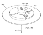
- Figures 2A, 2B , and 2C illustrate an exemplary analyte sensing device in a partially exploded view ( Figure 2A ), a partial perspective view ( Figure 2B ), and an assembled perspective view ( Figure 2C );
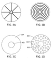
- Figures 3A , 03B, 3C, and 3D illustrate lower surface features of an analyte sensing device base
- Figure 4 illustrates a sensing electrode insertion aid
- Figure 5 illustrates an exploded view of an analyte sensing device, a sensing electrode insertion aid, and an associated overbandage
- Figures 6A and 6B illustrate an exemplary analyte sensing device with a plurality of sensing electrodes in accordance with various embodiments of the present invention
- FIGS. 7A, 7B, 7C, and 7D illustrate various configurations of sensing electrodes in accordance with various embodiments of the present invention
- FIGS 8A and 8B illustrate various configurations of sensing electrodes in accordance with various embodiments of the present invention
- Figure 9 illustrates an exemplary analyte sensing system in accordance with various embodiments of the present invention.
- Figures 10A and 10B illustrate an exemplary embodiment of an analyte sensing device in which a main body is movable or slidable with respect to an outer support sleeve.
- Coupled may mean that two or more elements are in direct physical or electrical contact. However, “coupled” may also mean that two or more elements are not in direct contact with each other, but yet still cooperate or interact with each other.
- a phrase in the form "A/B” or “A and/or B” means “(A), (B), or (A and B)".
- a phrase in the form "at least one of A, B, and C” means “(A), (B), (C), (A and B), (A and C), (B and C), or (A, B and C)”.
- a phrase in the form "(A)B” means "(B) or (AB)" that is, A is an optional element.
- the present invention provides an analyte sensing device according to claim 1 Further preferred embodiments of the invention are defined in the dependent claims.
- each sensing electrode may serve as an anode, a cathode, or a combination of an anode and cathode. In embodiments, there may be any suitable number of electrodes, such as 2, 3, 4, 5, 10, 15, 20, 30, 40, or more sensing electrodes.
- a plurality of sensing electrodes may comprise one or moro anodes and one or more cathodes. In an embodiment, a plurality of sensing electrodes may comprise an equal number of anodes and cathodes, or, in an embodiment, there may be an unequal number of anodes and cathodes. In an embodiment, one or more sensing electrodes may comprise both an anode and a cathode on a single sensing electrode. Additional details pertaining to suitable sensing electrodes may be found in US Patent Nos. 5,965,380 ; 5,165,407 ; 7,146,202 ; and US Patent Application No. 10/640,980 .
- various sensing electrodes of a plurality of sensing electrodes may be each configured to detect different analytes, or, in an embodiment, each sensing electrode may be configured to detect the same analyte, such as lactate, glucose, etc.
- a plurality of sensing electrodes are provided and may serve as the anode(s), while a connected base unit (main body) may have a skin-contact surface that serves as the cathode.
- an analyte sensing device comprising a main body configured to reside on skin of an individual when in use, the main body having one or more electrical components, and an analyte sensing electrode extending substantially perpendicularly from and electrically coupled to the main body, the analyte sensing electrode configured for insertion into the skin of the individual.
- substantially perpendicularly refers to an angle of orientation that is essentially 90°, although some reasonable degree of departure from 90° is tolerated, such as +/- 5-10°.
- Figure 1 illustrates an exemplary analyte sensing device 100 with a sensing electrode 102.
- Analyte sensing device 100 also has a main body 104 in one or more parts in which and/or on which may be housed/coupled one more electrical components such as a memory component, a battery component, a transmitter, a receiver, a transceiver, a processor, and/or a display component, etc.
- One or more electrical components may be provided in/on an associated device (not shown) adapted to be electrically coupled to analyte sensing device 100, such as coupled to main body 104.
- An insertion device 106 may also be provided, which may comprise one or more parts whether affixed to main body 104, removable from main body 104, or otherwise coupled to main body 104. Insertion device 106 may be a passive guidance mechanism into which or through which sensing electrode 102 may be inserted. Insertion device 106 may have contained therein, or may be couplable to a separate device having, a motive force device, such as a spring, configured to provide a motive force to sensing electrode 102 to drive sensing electrode 102 into skin. Insertion device 106 may be absent, or may be simply a location where a user (or another individual) may press to manually insert sensing electrode 102 into skin.
- Sensing electrode 102 may be coated along a portion of its length by a layer of dielectric 108, such as constructed of polyimide. Sensing electrode 102 may be an anode. Sensing electrode 102 may be both an anode and a cathode. For example, a silver or silver/silver chloride wire coil or sleeve may be disposed on/around a portion of dielectric 108 to serve as a reference electrode. Part of or the entire lower surface 110 of main body 104 may be a cathode (reference electrode).
- Suitable cathode materials include, but are not limited to, silver or silver/silver chloride.
- Suitable anode materials include, but are not limited to, platinum, palladium, and gold.
- a sensing electrode may be a combination anode and cathode such as described in US Patent No. 7,146,202 , and US Patent Application No. 10/640,960 .
- FIG. 1 shows sensing electrode 102 exiting main body 104 at a central point of surface 110, although, sensing electrode 102 may exit main body 104 at off-center locations.
- Sensing electrode 102 may form a variety of angles with main body 104, including 90°. Other examples may utilize other angles such as 20°, 40°, 60°, or 80°. A benefit of a 90° angle of orientation is that sensing electrode 102 may penetrate to the greatest depth in the skin with a given length electrode. A smaller angle (20°, 40°, etc.) may require using a longer electrode to reach a particular desired depth of penetration, such as to reach subcutaneous tissue. In an example in which sensing electrode 102 is configured at a 90° angle with respect to main body 104, a suitable length of sensing electrode 102 may have approximately 4-6 mm extending outside main body 104.
- sensing electrode 102 is partially covered with dielectric 108, of the 4-6 mm extending out of main body 104, approximately 3 mm of sensing electrode 102 may extend beyond dielectric 108. In an example, when using a different angle of insertion, a longer sensing electrode 102 may be used to provide a desired depth of skin penetration.
- Sensing electrode 102 may be electrically coupled to one or more electrical contacts and/or electrical components in, on, or associated with main body 104.
- Sensing electrode 102 may be at least partially covered with one or more membranes to manage the amount of oxygen, analyte, and/or other elements/compounds that contact sensing electrode 102.
- membranes to manage the amount of oxygen, analyte, and/or other elements/compounds that contact sensing electrode 102.
- Exemplary suitable membranes may be found in US Patent Nos. 5,165,407 and 6,613,379 ,
- an analyte sensing device 200 may have an electronics assembly 204 that may be in one or more portions, such as multiple portions at least partially connected together using a flex cable or other suitable connector(s).
- Electronics assembly 204 may have one more electrical components such as a memory component, a battery component, a transmitter, a receiver, a transceiver, a processor, and/or a display component, etc.
- the particular orientation of electronics assembly 204 being substantially in a circular, low-profile arrangement is exemplary. In embodiments, other arrangements may be utilized.
- Electronics assembly 204 may be associated with a base 210.
- electronics assembly 204 may be coupled to base 210 using adhesive or an integrated mechanism (snap, press-fit arrangement, mechanical guide/track, etc.) that allows for coupling and decoupling of electronics assembly 204 and base 210.
- Base 210 may provide one or more features such as mechanical support for electronics assembly 204, adhesive coupling to the skin surface of an individual, and/or serving as a reference electrode.
- base 210 may be a flexible substrate, such as a bandage.
- Base 210 may have an adhesive lower surface, which, if present, may be covered at least partially by a removable release liner prior to use.
- Adhesive may be applied to the lower surface of base 210 uniformly or randomly or in a pattern, for example forming channels ( Figure 3A ) or circumferential circles ( Figure 3B ). Utilizing adhesive that covers less than the entire lower surface of base 210 allows the skin to more freely sweat without excessive glandular occlusion and/or offers opportunities for water vapor to escape from under the bandage along the channels or through base 210. In an example in which circumferential circles are used, a larger amount of or a stronger type of adhesive may be used for the innermost and/or outermost circles of adhesive as those regions may be most important for securing sensing electrode 202 in skin (to avoid pistoning or other movement(s) of the electrode) and for maintaining device 200 on the skin. Adhesive applied to the lower surface of base 210 may have embedded/dispersed therein a silver/silver chloride additive to serve as a reference electrode. Wherein including adhesive or not, the lower surface of base 210 may serve as a reference electrode.
- FIG 3C illustrates an additional embodiment of a lower surface arrangement of a base (such as base 210 shown in Figures 2A and 2C ).
- sensing electrode 302 is represented by a circle; however, the actual diameter of the sensing electrode may be smaller than the diameter of the illustrated circle. The diameter of the illustrated circle reflects the amount of space allocated to sensing electrode 302.
- Sensing electrode 302 may be an anode, cathode, or combination anode and cathode.
- Sensing electrode 302 may be an anode and lower surface (skin contact surface) 304 may be a cathode.
- Surface 304 may be a cathode by being partially or completely constructed from a suitable material, such as silver/silver chloride, or by having a suitable material applied thereto.
- Figure 3D illustrates an additional example of a lower surface arrangement of a base (such as base 210 shown in Figures 2A and 2C ) of an analyte sensor assembly.
- sensing electrode 302 is represented by a circle; however, the actual diameter of the sensing electrode may be smaller than the diameter of the illustrated circle. The diameter of the illustrated circle reflects the amount of space allocated to sensing electrode 302.
- sensing electrode 302 may be an anode, cathode, or combination anode and cathode.
- Sensing electrode 302 may be an anode and surface protrusions 306 (small bumps or mounds) may each be a cathode or may collectively be a single cathode.
- Protrusions 306 may be a cathode(s) by being partially or completely constructed from a suitable material, such as silver/silver chloride, or by having a suitable material applied thereto.
- Surface 308 may be an adhesive or may have an adhesive applied thereto.
- cap 206 coupled to electronics assembly 204 is shown a cap 206 that is configured to couple physically and/or electrically with a corresponding subassembly 208 and subassembly housing 209 associated with base 210.
- Cap 206 is provided with one or more components to engage with subassembly 208 and housing 209.
- Cap 206 has a "key" protrusion 212 that is configured to fit within vertical slot 214 and to slide along horizontal slot 216 when cap 206 is rotated about subassembly housing 209.
- protrusion 212 may bend contact 218 such that contact 218 is moved into electrical contact with electrode 202.
- Contact 218 then provides an electrical pathway from electrode 202 through contact 218, through one or more portions of cap 206, such as through configured electrical contacts 207, and into electronics assembly 204.
- Each of the electrical pathways are not shown in detail but may be formed with any suitable material using one or more known or later developed fabrication processes.
- Some or all of the components may be configured to be disposable or reusable.
- Electronics assembly 204 and cap 206 may be configured to be reusable.
- Base 210, subassembly 208, subassembly housing 209, and electrode 202 may be configured to be disposable.
- Cap 206 may be configured to engage with subassembly 208 to move electrode 202 into skin.
- a separate insertion device may be used to move electrode 202 into skin.
- Such an insertion device may be mated to subassembly 208 and/or subassembly housing 209 to provide a motive force to subassembly 208 to move electrode 202 into skin.
- a motive force may be provided manually by a user.
- Sensing electrodes may be rigid or flexible. Sensing electrodes may be constructed with blunt or sharpened skin-penetrating distal ends.
- an analyte sensing device may be provided with a short hollow trocar through which a sensing electrode may pass.
- Figure 4 illustrates a sensing electrode insertion aid/device 400 (also referred to herein as a thumbtack) that may provide an initial hole in skin into which a sensing electrode may be simultaneously or subsequently inserted.
- Device 400 has a short hollow trocar 402 that is relatively sharp to provide for easy penetration of skin to a defined depth.
- Device 400 may have a base 404 and a docking port 406 to which may be coupled an analyte sensor assembly.
- Docking port 406 may comprise an extended ridge 408 or other such mechanism that may engage with one or more features on the analyte sensor assembly to aid in securing analyte sensor assembly to device 400.
- Docking port 406 may also have an opening 410 at the upper surface thereof to accept a sensing electrode and to allow the sensing electrode to pass through docking port 406 and through trocar 402.
- Trocar 402 may be constructed of a metal, plastic, etc. Trocar 402 may be constructed of a shape memory material, a thermoplastic, or other material having a temperature-dependent structural integrity such that when inserted into a body, the temperature of trocar 402 may be increased and trocar 402 may soften. A softened trocar 402 may be more comfortable to a patient.
- Trocar 402 may be approximately 1-5 mm, such as 2-3 mm, in length.
- an analyte sensing electrode insertion aid comprising a base configured to reside on skin of an individual when in use, the main body having at least one hole passing from an upper portion to a lower portion of the base, and a hollow trocar extending substantially perpendicularly from and coupled to the base, the trocar providing a hole that couples to the hole of the base such that a passage is provided from the upper portion of the base through the base and through the trocar, the passage configured to directionally guide an analyte sensing electrode into skin of the individual.
- FIG. 5 illustrates an exploded view of an analyte sensor assembly 200 poised for engagement with a thumbtack device 400. Opening 410 of docking port 406 may be provided with sloped interior walls to assist in guiding sensing electrode 202 into a hole (not shown) to allow sensing electrode 202 to pass through docking port 406 and through trocar 402. Also shown in Figure 5 is an overbandage 510 that may be used to cover analyte sensor assembly 200 to protect various underlying components from moisture, debris, contact, etc. In an embodiment, overbandage 510 may be flexible to account for various underlying contours.
- overbandage 510 may be configured with one or more integrated/formed extended surface formations 504 that may form a corresponding cavity on a reverse surface of overbandage 510 to accommodate one or more features of the underlying analyte sensor assembly 200.
- An overbandage such as overbandage 510, may have an approximate size of 2-4 inches, such as approximately 3 inches, in diameter.
- a base (whether in the form of a bandage or not), such as base 210, may have an approximate size of 1-2 inches, such as approximately 1.5 inches, in diameter.
- a plurality of sensing electrode is utilized. Such an embodiment may increase the amount of analyte that may be detected at a given time which may be useful if a single sensing electrode has a low sensitivity or a low sensitivity in the particular environment.
- an analyte sensing device comprising a main body configured to reside on skin of an individual when in use, the main body having one or more electrical components, and a plurality of analyte sensing electrodes extending from and electrically coupled to the main body, the analyte sensing electrodes configured for insertion into the skin of the individual.
- various calculations may be performed on the measured data.
- the values from the sensing electrodes may be averaged, various ones may be used while other values may be discarded, calibration may be independent for each sensing electrode, etc.
- a method for measuring analyte in an individual comprising inserting a portion of an analyte sensing device into skin of an individual, the analyte sensing device comprising a main body configured to reside on the skin of the individual when in use, the main body having one or more electrical components, and a plurality of analyte sensing electrodes extending from and electrically coupled to the main body, the analyte sensing electrodes configured for insertion into the skin of the individual, and measuring an amount of analyte detected directly or indirectly by one or more of the plurality of analyte sensing electrodes.
- the phrase "directly or indirectly" is intended to cover measurement of analyte or a proxy for a particular analyte, for example a product of a reaction involving a particular analyte.
- Figures 6A and 6B illustrate an exemplary analyte sensing device 600 with a plurality of sensing electrodes 602.
- Analyte sensing device 600 also has a main body 604 in which may be housed one more electrical components such as a memory component, a battery component, a transmitter, a receiver, a transceiver, a processor, and/or a display component, etc.
- one or more electrical components may be provided in an associated device (not shown) adapted to be electrically coupled to the analyte sensing device.
- Each sensing electrode 602 may serve as an anode, a cathode, or a combination of an anode and cathode.
- Suitable cathode materials include, but are not limited to, silver or silver/silver chloride.
- suitable anode materials include, but are not limited to, platinum, palladium, and gold.
- a sensing electrode 602 may be a combination anode and cathode such as described in US Patent No. 7,146,202 , and US Patent Application No. 10/640,980 .
- Each sensing electrode may be an anode while a connected base unit (main body) 604 may have a skin-contact surface 606 that serves as the cathode.
- sensing electrodes 702 may be utilized.
- Each sensing electrode 702 is represented by a circle; however, the actual diameter of the sensing electrode is typically smaller than the diameter of the illustrated circle.
- the diameter of the illustrated circle reflects the amount of space allocated to each sensing electrode 702 to ensure that the sensing electrodes 702 are not too closely packed and to achieve a suitable degree of tissue compression. If the sensing electrodes 702 are too closely packed, an unreasonably high degree of tissue compression may be needed to puncture the skin.
- the space allocated for each sensing electrode may be approximately 2-3 mm in diameter, whereas the actual diameter of a suitable exemplary sensor may be approximately 100-200 ⁇ m.
- Figure 7A illustrates an example in which an analyte sensing device 700 has nineteen sensing electrodes 702. With the defined allocated space for each sensing electrode 702, Figure 7A shows a maximized number of sensing electrodes 702 for the given space.
- Figures 7B and 7C illustrate a less than maximal number of sensing electrodes 702 for the given space (given a predefined allocated space for each electrode).
- Figure 7B illustrates a loosely arranged set of sensing electrodes 702
- Figure 7C illustrates a more densely arranged set of sensing electrodes 702.
- a more densely arranged set of sensing electrodes 702 generally results in more uniform pressure being applied to each sensing electrode 702.
- Figure 7D illustrates a set of sensing electrodes 702 with an allocated space for each sensing electrode 702 that is larger than that shown in Figures 7A, 7B, and 7C .
- a smaller number of sensing electrodes 702 and/or an increased amount of allocated space for each sensing electrode 702 may result in reduced tissue compression required to insert the sensing electrodes 702 into skin.
- each sensing electrode may independently be an anode, cathode, or a combination anode and cathode.
- One or more of the sensing electrodes may be an anode and the skin-contact surface of device 700 may be a cathode.
- Figures 8A and 8B illustrate anodes 808, such as constructed of platinum, and cathodes 810, such as constructed of silver or silver/silver chloride, coupled to analyte sensing device 800.
- anodes 808 such as constructed of platinum
- cathodes 810 such as constructed of silver or silver/silver chloride
- the plurality ofsensing electrodes comprises a membrane system or series of layered membranes.
- Such membranes include an interferent reducing inner layer, an enzyme layer (for example containing glucose oxidase, lactate oxidase, or lactate dehydrogenase), and a permselective outer layer.
- a silane layer may be provided under and/or over the enzyme layer. Additional details pertaining to suitable membranes may be found in US Patent Nos. 5,165,407 and 6,613,379 .
- a membrane system or at least one layer of a series of layered membranes may cover all or only a part of the sensing electrodes.
- a partially covered/surrounded sensing electrode may be constructed, for example, by dip coating, a deposition process, etc.
- a bare wire sensing electrode (one without an insulating layer of dielectric) may have a membrane or membrane system covering and surrounding only a portion of the sensing electrode, in particular, covering and surrounding only a portion of the sensing electrode that is intended to reside within the tissue of a user when in use.
- an enzyme layer containing glucose oxidase one benefit of such an arrangement is to maintain the enzyme layer within the tissue even when the sensing electrode experiences some movement relative to the skin to minimize motion-related artifacts.
- a main body may have one or more bare wire anodes with an enzyme layer on a distal portion thereof, and one or more separate wire cathodes.
- a bare wire anode or cathode may also have at least a portion thereof covered with a dielectric, such as polyimide.
- an analyte sensing device having a plurality of sensing electrodes may have a footprint approximately the size of a standard thumbtack or approximately the size of a quarter dollar (approximately 25 mm diameter) or smaller, such as approximately 10 mm.
- a plurality of sensing electrodes may each have the same length, or the lengths may vary in order to penetrate the skin to different depths.
- One or more sensing electrodes may have a length that only penetrates through the epidermis and into the dermis slightly thus picking up the majority of glucose from interstitial fluid in the outer skin layers.
- a sensing electrode may extend from an associated sensing device by approximately 3 mm to approximately 6 mm.
- a sensing electrode may extend from an associated sensing device perpendicular to the major surface of the sensing device, or may extend from the sensing device at an angle.
- a plurality of sensing electrodes may each have the same outer diameter, or the outer diameters of the sensing electrodes may vary.
- a sensing electrode may have an outer diameter of approximately 100-400 microns, or, in an embodiment, approximately 330 microns or smaller.
- the distal end (skin contact end) of a sensing electrode may be formed, cut, and/or sharpened to form a variety of shapes of points/ends as desired for ease of insertion.
- a sensing electrode may have either a blunt distal end or an end that is cut on the bias for easier insertion.
- An analyte sensing device may be attached to skin, at least in part, by inserting the associated sensing electrodes into the skin.
- the analyte sensing device may be inserted manually by a user or another individual.
- the analyte sensing device may be inserted using an associated insertion device (whether permanent or removably affixed).
- An associated insertion device may provide a separate motive force, such as with a spring, compressed gas, etc. Additional details regarding suitable insertion devices may be found in US Patent No. 6,695,860 and US Patent Application No. 11/558,394 .
- Additional mechanisms may be provided to secure an analyte sensing device to skin.
- a sensing device may be inserted into skin of an appendage or another portion of the body, and a flexible or elastic compression band may be further wrapped around the appendage (such as around the upper arm or thigh) or around another portion of the body to hold the analyte sensing device securely against the user's skin.
- An analyte sensing device may be coupled to an adhesive bandage prior to insertion into the skin, or an adhesive bandage may be first applied to skin and an analyte sensing device as described herein may then be coupled to the bandage and inserted into the skin.
- An analyte sensing device and/or an associated bandage/patch may also comprise various antimicrobial agents. Additional details regarding adhesive bandages may be found in US Patent Application No. 11/609,768 .
- An analyte sensing device may be integrated into or onto a bandage such that the user may remove a release liner on the bottom side of the bandage/patch and may press the sensor electrodes into the skin (or with use of an insertion device).
- the adhesive assists in securing the analyte sensing device on the skin.
- the footprint of the coupled components may be, for example, the size of a silver dollar, or approximately 40 mm or smaller, with the analyte sensing device accounting for approximately 40-70%, such as 50-60%, of that footprint.
- the various signals from the sensing electrodes may be averaged to obtain an average analyte value for the analyte sensing device.
- Signal averaging software may be used in conjunction with an analyte sensing device having multiple sensing electrodes to account for potential variations in the signals measured from one or more of the sensing electrodes.
- One or more sensing electrodes may not be functioning properly due to insufficient electrical connections, malfunctioning membranes, insufficient interstitial fluid found in the region in which the particular electrode resides, etc.
- Such malfunctioning and/or variation may be addressed by utilizing software-driven mathematical averaging to remove the non-functioning or statistically outlying value(s).
- one or more of the sensing electrodes may be excluded from contributing to the measured analyte value if that sensing electrode is determined to be providing a value that differs sufficiently from an average value of the remaining sensing electrodes.
- a particular value may be excluded or values measured by a particular sensing electrode may be excluded for a set period of time, or for the period of time the sensing electrode is returning an outlying value.
- a sensing electrode that has been excluded from the measurement calculations may be rejoined with the other sensing electrodes when it is determined to be producing suitable values.
- An analyte sensing device having a plurality of electrodes, or one or more associated devices may further comprise electronic circuitry and components in any desired structural relationship adapted to, in part, receive an electrical signal from an associated sensor and, optionally, to transmit a further signal, for example to an external electronic monitoring unit that is responsive to the sensor signal.
- the circuitry and other components may or may not include a printed circuit board, a tethered or wired system, etc. Signal transmission may occur over the air with electromagnetic waves, such as RF communication, or data may be read using inductive coupling. Transmission may be over a wire or via another direct connection.
- Additional components may be housed in one or more separate modules that may be coupled to (for example, snapped to, wired to, or in wireless communication with) the analyte sensing device.
- the separate module may contain a memory component, a battery component, a transmitter, a receiver, a transceiver, a processor, and/or a display component, etc.
- An analyte sensing device may have an integrated power source such as a battery, for example a coin-cell battery.
- a battery for example a coin-cell battery.
- the entire top surface of the analyte sensing device may be formed by a battery.
- An analyte sensing device and/or any other associated devices/components may be disposable, reusable, or the device(s) may be resposable.
- An analyte sensing device may be a disposable unit. Coupled to the analyte sensing device, may be a reusable unit. Such a reusable unit may comprise additional electronics and/or other components that either do not fit into the disposable unit, or are preferably made reusable due to cost.
- An analyte sensing device having a circular profile may be further encircled by a reusable unit that surrounds the analyte sensing device.
- An analyte sensing device as described above may be encircled such as by a donut-shaped reusable unit, or may be encircled and capped so that the top of the coupled device is the reusable unit.
- Figure 9 illustrates an exemplary sensing system 900.
- system 900 may be resposable.
- analyte sensing device body 904 may be disposable and electronics unit 920 may be reusable.
- Device body 904 may be reusable and electronics unit 920 may be disposable.
- the reusable portion may contain one or more of the expensive electronic components and/or those that have a usable life longer than that of the sensing electrodes.
- electronics unit 920 may fit over and around analyte sensing device body 904 to electrically couple the components.
- Analyte sensing device body 904 further has sensing electrodes 904 extending therefrom.
- Sensing electrodes may be coupled to a main body which is movable or slidable with respect to another element which in-turn encloses the sensing electrodes when in a retracted position.
- the sensing electrodes may then be pushed through one or more openings in the enclosing element to be inserted into skin.
- the one or more openings may be covered by a film or foil and/or there may be present a bladder or balloon that is pierced during the extension/insertion process.
- Figures 10A and 10B illustrate an example of an analyte sensing device 1000 in which a main body 1004 is movable or slidable with respect to an outer support sleeve 1022.
- Figure 6A illustrates main body 1004 and sensing electrodes 1002 in a partially retracted position
- Figure 10B illustrates main body 1004 and sensing electrodes 1002 in a more extended position simulating the action of the components of sensing device 1000 when sensing electrodes 1002 are inserted into skin.
- Outer support sleeve 1022 may contain various electronic components, one or more of which may be coupled to main body 1004, for example using a variety of electrical contacts or flexible wires, etc. Outer support sleeve 1022 may be disposable or reusable. Additional structures may be provided, such as a separate electronics unit (such as element 920 shown in Figure 9 ).
- sensing electrodes 1002 may be moved from a completely enclosed or retracted position to a fully extended position by moving main body 1004 with respect to sleeve 1022.
- a foil, film, or bladder may be provided at the lower base of sleeve 1022 to enclose the bottom of sleeve 1022 and secure sensing electrodes 1002 within sleeve 1022 until such time as sensing electrodes 1002 are pushed through the foil, film, or bladder.
- Sleeve 1022 may include a series of holes on a lower surface thereof through which electrodes 1002 may pass before being inserted into skin or in which electrodes 1002 may be held/guided.
- An insertion force may be provided by a user or by a separate device, such as a spring.
- a retraction force may be provided by a user or a separate device, such as a spring.
- Suitable ergonomic structures may be incorporated into main body 1004 and/or sleeve 1022 to ease the insertion process and/or to make the use of device 1000 more comfortable for the user.
- an analyte sensing device comprising a main body having one or more electrical components, the main body having a plurality of analyte sensing electrodes extending therefrom and electrically coupled thereto, and an outer support sleeve having an interior cavity, wherein the main body is movable within the interior cavity and movable with respect to the outer support sleeve from a position in which the plurality of analyte sensing electrodes are fully retracted into the interior cavity to a position in which the plurality of analyte sensing electrodes are extended from the outer support sleeve.
- Sensing electrodes in accordance with embodiments herein may be formed by any suitable process including wire machining and deposition/coating processes, chemical etching or other micromechanical processes.
- the sensing electrodes may be grown as "whiskers” from a silicon chip base.
Landscapes
- Health & Medical Sciences (AREA)
- Life Sciences & Earth Sciences (AREA)
- Physics & Mathematics (AREA)
- Biomedical Technology (AREA)
- Medical Informatics (AREA)
- Veterinary Medicine (AREA)
- Public Health (AREA)
- Biophysics (AREA)
- Pathology (AREA)
- Engineering & Computer Science (AREA)
- General Health & Medical Sciences (AREA)
- Heart & Thoracic Surgery (AREA)
- Animal Behavior & Ethology (AREA)
- Molecular Biology (AREA)
- Surgery (AREA)
- Optics & Photonics (AREA)
- Chemical & Material Sciences (AREA)
- Chemical Kinetics & Catalysis (AREA)
- General Chemical & Material Sciences (AREA)
- Emergency Medicine (AREA)
- Measurement Of The Respiration, Hearing Ability, Form, And Blood Characteristics Of Living Organisms (AREA)
Claims (12)
- Dispositif de détection d'analytes (600, 1000), comprenant :un corps principal (604, 1004) configuré pour résider à l'usage sur la peau d'un individu, le corps principal (604, 1004) comportant un ou plusieurs composants électriques ;caractérisé en ce que le dispositif de détection d'analytes (600, 1000) comprend en outreune pluralité d'électrodes de détection d'analytes (602, 1002) s'étendant depuis et électriquement couplées avec le corps principal (604, 1004), les électrodes de détection d'analytes (602, 1002) étant configurées pour insertion dans la peau de l'individu, chaque électrode de détection d'analytes (602, 1002) comprenant un système de membrane comportant une couche interne réduisant les interférences, une couche d'enzymes, et une couche externe à perméabilité sélective.
- Dispositif de détection d'analytes (600, 1000) selon la revendication 1, dans lequel la pluralité d'électrodes de détection d'analytes (602, 1002) est constituée d'anodes.
- Dispositif de détection d'analytes (600, 1000) selon la revendication 1 ou 2, dans lequel une surface de contact avec la peau (606) du corps principal (604, 1004) est une cathode.
- Dispositif de détection d'analytes (600, 1000) selon la revendication 3, dans lequel la surface de contact avec la peau (606) du corps principal (604, 1004) comprend des saillies superficielles qui comprennent la cathode.
- Dispositif de détection d'analytes (600, 1000) selon l'une quelconque des revendications 1 à 4, dans lequel le corps principal (604, 1004) est un substrat flexible.
- Dispositif de détection d'analytes (600, 1000) selon l'une quelconque des revendications 1 à 5, comprenant en outre un adhésif à motif sur une surface de contact avec la peau (606) du corps principal (604, 1004).
- Dispositif de détection d'analytes (600, 1000) selon l'une quelconque des revendications 1 à 5, comprenant en outre un adhésif sur une surface de contact avec la peau (606) du corps principal (604, 1004), l'adhésif contenant de l'argent/chlorure d'argent.
- Dispositif de détection d'analytes (600, 1000) selon la revendication 1, dans lequel la pluralité d'électrodes de détection d'analytes (602, 1002) s'étend de façon sensiblement perpendiculaire depuis le corps principal (604, 1004).
- Dispositif de détection d'analytes (600, 1000) selon la revendication 1, dans lequel la pluralité d'électrodes de détection d'analytes (602, 1002) est configurée pour détecter de multiples analytes, chaque électrode de détection d'analytes (602, 1002) étant configurée pour détecter un seul analyte.
- Dispositif de détection d'analytes (600, 1000) selon l'une quelconque des revendications 1 à 9, comprenant en outre
un manchon de support externe (1022) comportant une cavité intérieure, le corps principal (604, 1004) étant mobile dans la cavité intérieure et mobile par rapport au manchon de support externe (1022) depuis une position dans laquelle la pluralité d'électrodes de détection d'analytes (602, 1002) sont totalement rétractées dans la cavité intérieure jusqu'à une position dans laquelle la pluralité d'électrodes de détection d'analytes (602, 1002) sont déployées depuis le manchon de support externe (1022). - Dispositif de détection d'analytes (600, 1000) selon la revendication 10, dans lequel le manchon externe (1022) comprend en outre une barrière qui doit être percée par la pluralité d'électrodes de détection d'analytes (602, 1002) lorsqu'elles sont déplacées d'une position totalement rétractée à une position déployée.
- Dispositif de détection d'analytes (600, 1000) selon l'une quelconque des revendications 1 à 11, comprenant en outre un processeur de signal pour moyenner la variation de signal sur la pluralité d'électrodes de détection d'analytes (602, 1002).
Applications Claiming Priority (2)
| Application Number | Priority Date | Filing Date | Title |
|---|---|---|---|
| US91001307P | 2007-04-04 | 2007-04-04 | |
| PCT/US2008/059417 WO2008124597A1 (fr) | 2007-04-04 | 2008-04-04 | Dispositif de détection de substance à analyser ayant une ou plusieurs électrodes de détection |
Publications (3)
| Publication Number | Publication Date |
|---|---|
| EP2142096A1 EP2142096A1 (fr) | 2010-01-13 |
| EP2142096A4 EP2142096A4 (fr) | 2010-12-29 |
| EP2142096B1 true EP2142096B1 (fr) | 2013-01-09 |
Family
ID=39827565
Family Applications (1)
| Application Number | Title | Priority Date | Filing Date |
|---|---|---|---|
| EP08745118A Not-in-force EP2142096B1 (fr) | 2007-04-04 | 2008-04-04 | Dispositif de détection de substance à analyser ayant plusieurs électrodes de détection |
Country Status (6)
| Country | Link |
|---|---|
| US (1) | US20080249383A1 (fr) |
| EP (1) | EP2142096B1 (fr) |
| JP (1) | JP2010523227A (fr) |
| CN (1) | CN101686811A (fr) |
| CA (1) | CA2680841A1 (fr) |
| WO (1) | WO2008124597A1 (fr) |
Families Citing this family (45)
| Publication number | Priority date | Publication date | Assignee | Title |
|---|---|---|---|---|
| US20190357827A1 (en) | 2003-08-01 | 2019-11-28 | Dexcom, Inc. | Analyte sensor |
| US7920906B2 (en) | 2005-03-10 | 2011-04-05 | Dexcom, Inc. | System and methods for processing analyte sensor data for sensor calibration |
| US9247900B2 (en) | 2004-07-13 | 2016-02-02 | Dexcom, Inc. | Analyte sensor |
| US8989833B2 (en) | 2004-07-13 | 2015-03-24 | Dexcom, Inc. | Transcutaneous analyte sensor |
| WO2006127694A2 (fr) | 2004-07-13 | 2006-11-30 | Dexcom, Inc. | Detecteur d'analyte |
| US8512243B2 (en) | 2005-09-30 | 2013-08-20 | Abbott Diabetes Care Inc. | Integrated introducer and transmitter assembly and methods of use |
| US8029441B2 (en) | 2006-02-28 | 2011-10-04 | Abbott Diabetes Care Inc. | Analyte sensor transmitter unit configuration for a data monitoring and management system |
| US20080242293A1 (en) * | 2007-04-02 | 2008-10-02 | Cequint, Inc. | System and method for providing caller id name display in wireless communications system |
| EP2227132B1 (fr) | 2007-10-09 | 2023-03-08 | DexCom, Inc. | Système d'administration d'insuline intégré avec un capteur de glucose en continu |
| US8591455B2 (en) | 2008-02-21 | 2013-11-26 | Dexcom, Inc. | Systems and methods for customizing delivery of sensor data |
| US8700114B2 (en) * | 2008-07-31 | 2014-04-15 | Medtronic Minmed, Inc. | Analyte sensor apparatuses comprising multiple implantable sensor elements and methods for making and using them |
| US9402544B2 (en) | 2009-02-03 | 2016-08-02 | Abbott Diabetes Care Inc. | Analyte sensor and apparatus for insertion of the sensor |
| WO2011025549A1 (fr) | 2009-08-31 | 2011-03-03 | Abbott Diabetes Care Inc. | Dispositifs et procédés médicaux |
| CA2766685A1 (fr) | 2010-03-24 | 2011-12-29 | Abbott Diabetes Care Inc. | Appareils d'insertion de dispositifs medicaux et procedes d'insertion et d'utilisation de dispositifs medicaux |
| US9271671B2 (en) | 2010-04-16 | 2016-03-01 | Arkray, Inc. | Sensor and method for removing interfering substance |
| US9848809B2 (en) | 2011-04-15 | 2017-12-26 | Dexcom, Inc. | Advanced analyte sensor calibration and error detection |
| WO2013035455A1 (fr) | 2011-09-09 | 2013-03-14 | テルモ株式会社 | Dispositif d'insertion de capteur et procédé de fonctionnement de celui-ci |
| WO2013090215A2 (fr) | 2011-12-11 | 2013-06-20 | Abbot Diabetes Care Inc. | Dispositifs détecteurs d'analytes, connexions, et procédés |
| US20140213866A1 (en) | 2012-10-12 | 2014-07-31 | Dexcom, Inc. | Sensors for continuous analyte monitoring, and related methods |
| US20140107450A1 (en) | 2012-10-12 | 2014-04-17 | Dexcom, Inc. | Sensors for continuous analyte monitoring, and related methods |
| US20160161459A1 (en) * | 2013-07-16 | 2016-06-09 | R. Rouse | Apparatus for detection and delivery of volatilized compounds and related methods |
| CN104887242B (zh) | 2014-03-07 | 2018-08-28 | 上海移宇科技股份有限公司 | 分析物传感系统 |
| CA3220825A1 (fr) * | 2014-04-10 | 2015-10-15 | Dexcom, Inc. | Capteurs permettant une surveillance continue d'analytes et procedes associes |
| US20150289788A1 (en) | 2014-04-10 | 2015-10-15 | Dexcom, Inc. | Sensors for continuous analyte monitoring, and related methods |
| US11219413B2 (en) * | 2014-08-26 | 2022-01-11 | Dexcom, Inc. | Systems and methods for securing a continuous analyte sensor to a host |
| CN105873514B (zh) * | 2014-10-27 | 2018-10-26 | 深圳市光聚通讯技术开发有限公司 | 动态血糖采集装置及主机 |
| US10213139B2 (en) | 2015-05-14 | 2019-02-26 | Abbott Diabetes Care Inc. | Systems, devices, and methods for assembling an applicator and sensor control device |
| EP3138488B1 (fr) | 2015-09-02 | 2019-06-05 | Roche Diabetes Care GmbH | Module de détection et kit de détermination d'une concentration d'analyte |
| EP3138489B1 (fr) | 2015-09-02 | 2020-06-24 | Roche Diabetes Care GmbH | Kit permettant de déterminer une concentration d'analyte |
| EP3170452B1 (fr) * | 2015-11-19 | 2021-01-27 | Roche Diabetes Care GmbH | Ensemble capteur pour détecter au moins un analyte dans un fluide corporel |
| EP3804611B1 (fr) * | 2015-12-30 | 2024-07-17 | Dexcom, Inc. | Systèmes et procédés de capteur d'analyte transcutané |
| JP2018102576A (ja) * | 2016-12-26 | 2018-07-05 | アークレイ株式会社 | 測定装置、センサユニット、及び測定装置を設置する方法 |
| CN115444410B (zh) * | 2017-01-23 | 2025-08-15 | 雅培糖尿病护理公司 | 用于插入体内分析物传感器的施加器及组件 |
| EP3928688B1 (fr) | 2017-06-23 | 2022-06-01 | Dexcom, Inc. | Capteurs de substance à analyser transcutanés, applicateurs correspondants et moyeu d'aiguille comprenant une fonction anti-rotation |
| EP3928687B1 (fr) | 2017-10-24 | 2024-06-26 | Dexcom, Inc. | Dispositif portable avec un capteur d'analyte préconnecté |
| US11331022B2 (en) | 2017-10-24 | 2022-05-17 | Dexcom, Inc. | Pre-connected analyte sensors |
| JP7131948B2 (ja) * | 2018-04-23 | 2022-09-06 | 日本光電工業株式会社 | 検査装置、弾性部材、及び入力箱 |
| US20210236028A1 (en) * | 2018-05-17 | 2021-08-05 | Abbott Diabetes Care Inc. | Analyte sensor antimicrobial configurations and adhesives |
| DE202019005660U1 (de) | 2018-06-07 | 2021-07-12 | Abbott Diabetes Care, Inc. | Fokussierte Sterilisation und sterilisierte Teilanordnungen für Analytüberwachungssysteme |
| USD926325S1 (en) | 2018-06-22 | 2021-07-27 | Dexcom, Inc. | Wearable medical monitoring device |
| USD1002852S1 (en) | 2019-06-06 | 2023-10-24 | Abbott Diabetes Care Inc. | Analyte sensor device |
| TWI735138B (zh) * | 2019-08-02 | 2021-08-01 | 華廣生技股份有限公司 | 生理訊號傳感裝置 |
| US11957488B2 (en) * | 2020-02-07 | 2024-04-16 | Medtronic Minimed, Inc. | Systems for medical device breathability |
| US12186098B2 (en) | 2020-02-07 | 2025-01-07 | Medtronic Minimed, Inc. | Systems for medical device breathability |
| USD999913S1 (en) | 2020-12-21 | 2023-09-26 | Abbott Diabetes Care Inc | Analyte sensor inserter |
Family Cites Families (14)
| Publication number | Priority date | Publication date | Assignee | Title |
|---|---|---|---|---|
| US4094822A (en) * | 1974-12-26 | 1978-06-13 | Kater John A R | Bio-event electrode material |
| US4953552A (en) * | 1989-04-21 | 1990-09-04 | Demarzo Arthur P | Blood glucose monitoring system |
| US5165407A (en) | 1990-04-19 | 1992-11-24 | The University Of Kansas | Implantable glucose sensor |
| US5593852A (en) * | 1993-12-02 | 1997-01-14 | Heller; Adam | Subcutaneous glucose electrode |
| US5582184A (en) * | 1993-10-13 | 1996-12-10 | Integ Incorporated | Interstitial fluid collection and constituent measurement |
| JP3963485B2 (ja) * | 1997-04-11 | 2007-08-22 | アルザ コーポレイション | 最小限での侵入性の検出用装置 |
| CA2294610A1 (fr) * | 1997-06-16 | 1998-12-23 | George Moshe Katz | Procedes d'etalonnage et de test d'un capteur servant a mesurer un analyte in vivo et dispositifs utilises dans ces procedes |
| US6706159B2 (en) * | 2000-03-02 | 2004-03-16 | Diabetes Diagnostics | Combined lancet and electrochemical analyte-testing apparatus |
| GB0030929D0 (en) | 2000-12-19 | 2001-01-31 | Inverness Medical Ltd | Analyte measurement |
| US6952604B2 (en) * | 2001-12-21 | 2005-10-04 | Becton, Dickinson And Company | Minimally-invasive system and method for monitoring analyte levels |
| US7120483B2 (en) * | 2003-01-13 | 2006-10-10 | Isense Corporation | Methods for analyte sensing and measurement |
| EP1680014A4 (fr) * | 2003-10-14 | 2009-01-21 | Pelikan Technologies Inc | Procede et appareil fournissant une interface-utilisateur variable |
| WO2005051183A1 (fr) * | 2003-11-25 | 2005-06-09 | Novo Nordisk A/S | Sonde aiguille et mecanisme pour l'insertion de la sonde aiguille a travers la peau |
| CN100367906C (zh) | 2004-12-08 | 2008-02-13 | 圣美迪诺医疗科技(湖州)有限公司 | 皮下植入式生物传感器 |
-
2008
- 2008-04-04 EP EP08745118A patent/EP2142096B1/fr not_active Not-in-force
- 2008-04-04 US US12/062,969 patent/US20080249383A1/en not_active Abandoned
- 2008-04-04 CN CN200880010865A patent/CN101686811A/zh active Pending
- 2008-04-04 WO PCT/US2008/059417 patent/WO2008124597A1/fr not_active Ceased
- 2008-04-04 JP JP2010502323A patent/JP2010523227A/ja not_active Withdrawn
- 2008-04-04 CA CA002680841A patent/CA2680841A1/fr not_active Abandoned
Also Published As
| Publication number | Publication date |
|---|---|
| US20080249383A1 (en) | 2008-10-09 |
| CA2680841A1 (fr) | 2008-10-16 |
| EP2142096A4 (fr) | 2010-12-29 |
| EP2142096A1 (fr) | 2010-01-13 |
| CN101686811A (zh) | 2010-03-31 |
| WO2008124597A1 (fr) | 2008-10-16 |
| JP2010523227A (ja) | 2010-07-15 |
Similar Documents
| Publication | Publication Date | Title |
|---|---|---|
| US20080249383A1 (en) | Analyte sensing device having one or more sensing electrodes | |
| US12350042B2 (en) | Continuous analyte measurement systems and systems and methods for implanting them | |
| US10420488B2 (en) | Diagnostic device | |
| EP1385427B1 (fr) | Systeme de surveillance de fluide interstitiel portable | |
| JP4944802B2 (ja) | 血液センサとそれを有する血液検査装置 | |
| US5586553A (en) | Transcutaneous sensor insertion set | |
| JP4373217B2 (ja) | 被検体レベルをモニターする低侵襲システム及び方法 | |
| US20160278679A1 (en) | Medical devices and insertion systems and methods | |
| CN118613214A (zh) | 可穿戴分析物监测设备 | |
| JP2005520648A (ja) | 外傷を伴わない皮下挿入式デバイスの挿入 | |
| CN102665549B (zh) | 测定装置以及传感器留置方法 | |
| US20220273240A1 (en) | Needle sensor and method of manufacturing the same | |
| CN114391835B (zh) | 经皮分析物传感器系统 | |
| CN115151189B (zh) | 连续血糖测量装置 | |
| CN115175611A (zh) | 连续血糖测量装置 | |
| CN121263127A (zh) | 用于分析物监测的系统、装置和方法 | |
| EP2355705A2 (fr) | Biocapteur implantable à long terme | |
| CN217090725U (zh) | 传感器电极的安装结构 | |
| WO2026082302A1 (fr) | Ensemble à micro-aiguilles avec structures de détection et d'immobilisation pour appareil de détection à porter | |
| JP2004033374A (ja) | 体内情報検出ユニット | |
| WO2024254033A1 (fr) | Systèmes, dispositifs et procédés de surveillance d'analyte | |
| JP2025540093A (ja) | 分析物モニタリング装置 |
Legal Events
| Date | Code | Title | Description |
|---|---|---|---|
| PUAI | Public reference made under article 153(3) epc to a published international application that has entered the european phase |
Free format text: ORIGINAL CODE: 0009012 |
|
| 17P | Request for examination filed |
Effective date: 20091104 |
|
| AK | Designated contracting states |
Kind code of ref document: A1 Designated state(s): AT BE BG CH CY CZ DE DK EE ES FI FR GB GR HR HU IE IS IT LI LT LU LV MC MT NL NO PL PT RO SE SI SK TR |
|
| DAX | Request for extension of the european patent (deleted) | ||
| A4 | Supplementary search report drawn up and despatched |
Effective date: 20101130 |
|
| RIC1 | Information provided on ipc code assigned before grant |
Ipc: A61B 5/00 20060101ALI20101124BHEP Ipc: A61B 5/145 20060101AFI20081028BHEP |
|
| 17Q | First examination report despatched |
Effective date: 20110930 |
|
| GRAP | Despatch of communication of intention to grant a patent |
Free format text: ORIGINAL CODE: EPIDOSNIGR1 |
|
| GRAS | Grant fee paid |
Free format text: ORIGINAL CODE: EPIDOSNIGR3 |
|
| GRAA | (expected) grant |
Free format text: ORIGINAL CODE: 0009210 |
|
| AK | Designated contracting states |
Kind code of ref document: B1 Designated state(s): AT BE BG CH CY CZ DE DK EE ES FI FR GB GR HR HU IE IS IT LI LT LU LV MC MT NL NO PL PT RO SE SI SK TR |
|
| REG | Reference to a national code |
Ref country code: GB Ref legal event code: FG4D |
|
| REG | Reference to a national code |
Ref country code: AT Ref legal event code: REF Ref document number: 592272 Country of ref document: AT Kind code of ref document: T Effective date: 20130115 Ref country code: CH Ref legal event code: EP |
|
| REG | Reference to a national code |
Ref country code: IE Ref legal event code: FG4D |
|
| REG | Reference to a national code |
Ref country code: DE Ref legal event code: R096 Ref document number: 602008021546 Country of ref document: DE Effective date: 20130307 |
|
| PG25 | Lapsed in a contracting state [announced via postgrant information from national office to epo] |
Ref country code: SI Free format text: LAPSE BECAUSE OF FAILURE TO SUBMIT A TRANSLATION OF THE DESCRIPTION OR TO PAY THE FEE WITHIN THE PRESCRIBED TIME-LIMIT Effective date: 20130109 |
|
| REG | Reference to a national code |
Ref country code: NL Ref legal event code: VDEP Effective date: 20130109 |
|
| REG | Reference to a national code |
Ref country code: AT Ref legal event code: MK05 Ref document number: 592272 Country of ref document: AT Kind code of ref document: T Effective date: 20130109 |
|
| REG | Reference to a national code |
Ref country code: LT Ref legal event code: MG4D |
|
| PG25 | Lapsed in a contracting state [announced via postgrant information from national office to epo] |
Ref country code: LT Free format text: LAPSE BECAUSE OF FAILURE TO SUBMIT A TRANSLATION OF THE DESCRIPTION OR TO PAY THE FEE WITHIN THE PRESCRIBED TIME-LIMIT Effective date: 20130109 Ref country code: BG Free format text: LAPSE BECAUSE OF FAILURE TO SUBMIT A TRANSLATION OF THE DESCRIPTION OR TO PAY THE FEE WITHIN THE PRESCRIBED TIME-LIMIT Effective date: 20130409 Ref country code: IS Free format text: LAPSE BECAUSE OF FAILURE TO SUBMIT A TRANSLATION OF THE DESCRIPTION OR TO PAY THE FEE WITHIN THE PRESCRIBED TIME-LIMIT Effective date: 20130509 Ref country code: BE Free format text: LAPSE BECAUSE OF FAILURE TO SUBMIT A TRANSLATION OF THE DESCRIPTION OR TO PAY THE FEE WITHIN THE PRESCRIBED TIME-LIMIT Effective date: 20130109 Ref country code: NO Free format text: LAPSE BECAUSE OF FAILURE TO SUBMIT A TRANSLATION OF THE DESCRIPTION OR TO PAY THE FEE WITHIN THE PRESCRIBED TIME-LIMIT Effective date: 20130409 Ref country code: SE Free format text: LAPSE BECAUSE OF FAILURE TO SUBMIT A TRANSLATION OF THE DESCRIPTION OR TO PAY THE FEE WITHIN THE PRESCRIBED TIME-LIMIT Effective date: 20130109 Ref country code: ES Free format text: LAPSE BECAUSE OF FAILURE TO SUBMIT A TRANSLATION OF THE DESCRIPTION OR TO PAY THE FEE WITHIN THE PRESCRIBED TIME-LIMIT Effective date: 20130420 Ref country code: AT Free format text: LAPSE BECAUSE OF FAILURE TO SUBMIT A TRANSLATION OF THE DESCRIPTION OR TO PAY THE FEE WITHIN THE PRESCRIBED TIME-LIMIT Effective date: 20130109 |
|
| PGFP | Annual fee paid to national office [announced via postgrant information from national office to epo] |
Ref country code: DE Payment date: 20130429 Year of fee payment: 6 |
|
| PG25 | Lapsed in a contracting state [announced via postgrant information from national office to epo] |
Ref country code: GR Free format text: LAPSE BECAUSE OF FAILURE TO SUBMIT A TRANSLATION OF THE DESCRIPTION OR TO PAY THE FEE WITHIN THE PRESCRIBED TIME-LIMIT Effective date: 20130410 Ref country code: PT Free format text: LAPSE BECAUSE OF FAILURE TO SUBMIT A TRANSLATION OF THE DESCRIPTION OR TO PAY THE FEE WITHIN THE PRESCRIBED TIME-LIMIT Effective date: 20130509 Ref country code: FI Free format text: LAPSE BECAUSE OF FAILURE TO SUBMIT A TRANSLATION OF THE DESCRIPTION OR TO PAY THE FEE WITHIN THE PRESCRIBED TIME-LIMIT Effective date: 20130109 Ref country code: PL Free format text: LAPSE BECAUSE OF FAILURE TO SUBMIT A TRANSLATION OF THE DESCRIPTION OR TO PAY THE FEE WITHIN THE PRESCRIBED TIME-LIMIT Effective date: 20130109 Ref country code: LV Free format text: LAPSE BECAUSE OF FAILURE TO SUBMIT A TRANSLATION OF THE DESCRIPTION OR TO PAY THE FEE WITHIN THE PRESCRIBED TIME-LIMIT Effective date: 20130109 Ref country code: NL Free format text: LAPSE BECAUSE OF FAILURE TO SUBMIT A TRANSLATION OF THE DESCRIPTION OR TO PAY THE FEE WITHIN THE PRESCRIBED TIME-LIMIT Effective date: 20130109 |
|
| PG25 | Lapsed in a contracting state [announced via postgrant information from national office to epo] |
Ref country code: HR Free format text: LAPSE BECAUSE OF FAILURE TO SUBMIT A TRANSLATION OF THE DESCRIPTION OR TO PAY THE FEE WITHIN THE PRESCRIBED TIME-LIMIT Effective date: 20130109 |
|
| PG25 | Lapsed in a contracting state [announced via postgrant information from national office to epo] |
Ref country code: EE Free format text: LAPSE BECAUSE OF FAILURE TO SUBMIT A TRANSLATION OF THE DESCRIPTION OR TO PAY THE FEE WITHIN THE PRESCRIBED TIME-LIMIT Effective date: 20130109 Ref country code: SK Free format text: LAPSE BECAUSE OF FAILURE TO SUBMIT A TRANSLATION OF THE DESCRIPTION OR TO PAY THE FEE WITHIN THE PRESCRIBED TIME-LIMIT Effective date: 20130109 Ref country code: RO Free format text: LAPSE BECAUSE OF FAILURE TO SUBMIT A TRANSLATION OF THE DESCRIPTION OR TO PAY THE FEE WITHIN THE PRESCRIBED TIME-LIMIT Effective date: 20130109 Ref country code: CZ Free format text: LAPSE BECAUSE OF FAILURE TO SUBMIT A TRANSLATION OF THE DESCRIPTION OR TO PAY THE FEE WITHIN THE PRESCRIBED TIME-LIMIT Effective date: 20130109 Ref country code: DK Free format text: LAPSE BECAUSE OF FAILURE TO SUBMIT A TRANSLATION OF THE DESCRIPTION OR TO PAY THE FEE WITHIN THE PRESCRIBED TIME-LIMIT Effective date: 20130109 |
|
| PLBE | No opposition filed within time limit |
Free format text: ORIGINAL CODE: 0009261 |
|
| STAA | Information on the status of an ep patent application or granted ep patent |
Free format text: STATUS: NO OPPOSITION FILED WITHIN TIME LIMIT |
|
| PG25 | Lapsed in a contracting state [announced via postgrant information from national office to epo] |
Ref country code: CY Free format text: LAPSE BECAUSE OF FAILURE TO SUBMIT A TRANSLATION OF THE DESCRIPTION OR TO PAY THE FEE WITHIN THE PRESCRIBED TIME-LIMIT Effective date: 20130109 Ref country code: MC Free format text: LAPSE BECAUSE OF FAILURE TO SUBMIT A TRANSLATION OF THE DESCRIPTION OR TO PAY THE FEE WITHIN THE PRESCRIBED TIME-LIMIT Effective date: 20130109 |
|
| REG | Reference to a national code |
Ref country code: CH Ref legal event code: PL |
|
| 26N | No opposition filed |
Effective date: 20131010 |
|
| GBPC | Gb: european patent ceased through non-payment of renewal fee |
Effective date: 20130409 |
|
| PG25 | Lapsed in a contracting state [announced via postgrant information from national office to epo] |
Ref country code: IT Free format text: LAPSE BECAUSE OF FAILURE TO SUBMIT A TRANSLATION OF THE DESCRIPTION OR TO PAY THE FEE WITHIN THE PRESCRIBED TIME-LIMIT Effective date: 20130109 |
|
| REG | Reference to a national code |
Ref country code: IE Ref legal event code: MM4A |
|
| REG | Reference to a national code |
Ref country code: DE Ref legal event code: R097 Ref document number: 602008021546 Country of ref document: DE Effective date: 20131010 |
|
| PG25 | Lapsed in a contracting state [announced via postgrant information from national office to epo] |
Ref country code: LI Free format text: LAPSE BECAUSE OF NON-PAYMENT OF DUE FEES Effective date: 20130430 Ref country code: GB Free format text: LAPSE BECAUSE OF NON-PAYMENT OF DUE FEES Effective date: 20130409 Ref country code: CH Free format text: LAPSE BECAUSE OF NON-PAYMENT OF DUE FEES Effective date: 20130430 |
|
| REG | Reference to a national code |
Ref country code: FR Ref legal event code: ST Effective date: 20131231 |
|
| PG25 | Lapsed in a contracting state [announced via postgrant information from national office to epo] |
Ref country code: FR Free format text: LAPSE BECAUSE OF NON-PAYMENT OF DUE FEES Effective date: 20130430 |
|
| PG25 | Lapsed in a contracting state [announced via postgrant information from national office to epo] |
Ref country code: IE Free format text: LAPSE BECAUSE OF NON-PAYMENT OF DUE FEES Effective date: 20130404 |
|
| REG | Reference to a national code |
Ref country code: DE Ref legal event code: R119 Ref document number: 602008021546 Country of ref document: DE |
|
| REG | Reference to a national code |
Ref country code: DE Ref legal event code: R119 Ref document number: 602008021546 Country of ref document: DE Effective date: 20141101 |
|
| PG25 | Lapsed in a contracting state [announced via postgrant information from national office to epo] |
Ref country code: DE Free format text: LAPSE BECAUSE OF NON-PAYMENT OF DUE FEES Effective date: 20141101 |
|
| PG25 | Lapsed in a contracting state [announced via postgrant information from national office to epo] |
Ref country code: MT Free format text: LAPSE BECAUSE OF FAILURE TO SUBMIT A TRANSLATION OF THE DESCRIPTION OR TO PAY THE FEE WITHIN THE PRESCRIBED TIME-LIMIT Effective date: 20130109 |
|
| PG25 | Lapsed in a contracting state [announced via postgrant information from national office to epo] |
Ref country code: TR Free format text: LAPSE BECAUSE OF FAILURE TO SUBMIT A TRANSLATION OF THE DESCRIPTION OR TO PAY THE FEE WITHIN THE PRESCRIBED TIME-LIMIT Effective date: 20130109 |
|
| PG25 | Lapsed in a contracting state [announced via postgrant information from national office to epo] |
Ref country code: HU Free format text: LAPSE BECAUSE OF FAILURE TO SUBMIT A TRANSLATION OF THE DESCRIPTION OR TO PAY THE FEE WITHIN THE PRESCRIBED TIME-LIMIT; INVALID AB INITIO Effective date: 20080404 Ref country code: LU Free format text: LAPSE BECAUSE OF NON-PAYMENT OF DUE FEES Effective date: 20130404 |