EP2143181B1 - Kompakte laserquelle mit verringerter spektraler breite - Google Patents
Kompakte laserquelle mit verringerter spektraler breite Download PDFInfo
- Publication number
- EP2143181B1 EP2143181B1 EP08736560A EP08736560A EP2143181B1 EP 2143181 B1 EP2143181 B1 EP 2143181B1 EP 08736560 A EP08736560 A EP 08736560A EP 08736560 A EP08736560 A EP 08736560A EP 2143181 B1 EP2143181 B1 EP 2143181B1
- Authority
- EP
- European Patent Office
- Prior art keywords
- cavity
- laser
- polarisation
- output
- laser diode
- Prior art date
- Legal status (The legal status is an assumption and is not a legal conclusion. Google has not performed a legal analysis and makes no representation as to the accuracy of the status listed.)
- Not-in-force
Links
- 230000003595 spectral effect Effects 0.000 title description 9
- 230000003287 optical effect Effects 0.000 claims abstract description 58
- 230000005540 biological transmission Effects 0.000 claims abstract description 15
- 241000282326 Felis catus Species 0.000 claims description 2
- 238000001465 metallisation Methods 0.000 claims description 2
- 239000007787 solid Substances 0.000 claims description 2
- BJQHLKABXJIVAM-UHFFFAOYSA-N bis(2-ethylhexyl) phthalate Chemical compound CCCCC(CC)COC(=O)C1=CC=CC=C1C(=O)OCC(CC)CCCC BJQHLKABXJIVAM-UHFFFAOYSA-N 0.000 claims 2
- 238000001816 cooling Methods 0.000 abstract description 4
- 238000002474 experimental method Methods 0.000 abstract description 2
- 238000005305 interferometry Methods 0.000 abstract description 2
- 230000010287 polarization Effects 0.000 description 82
- 241001644893 Entandrophragma utile Species 0.000 description 3
- 230000000903 blocking effect Effects 0.000 description 2
- 238000001514 detection method Methods 0.000 description 2
- 238000010586 diagram Methods 0.000 description 2
- 235000021183 entrée Nutrition 0.000 description 2
- 238000000926 separation method Methods 0.000 description 2
- 241000680160 Opisthoproctidae Species 0.000 description 1
- 241000287107 Passer Species 0.000 description 1
- 230000000295 complement effect Effects 0.000 description 1
- 230000007423 decrease Effects 0.000 description 1
- 239000012212 insulator Substances 0.000 description 1
- 230000010354 integration Effects 0.000 description 1
- 238000004519 manufacturing process Methods 0.000 description 1
- 238000000034 method Methods 0.000 description 1
- 238000010408 sweeping Methods 0.000 description 1
Images


Classifications
-
- H—ELECTRICITY
- H01—ELECTRIC ELEMENTS
- H01S—DEVICES USING THE PROCESS OF LIGHT AMPLIFICATION BY STIMULATED EMISSION OF RADIATION [LASER] TO AMPLIFY OR GENERATE LIGHT; DEVICES USING STIMULATED EMISSION OF ELECTROMAGNETIC RADIATION IN WAVE RANGES OTHER THAN OPTICAL
- H01S5/00—Semiconductor lasers
- H01S5/10—Construction or shape of the optical resonator, e.g. extended or external cavity, coupled cavities, bent-guide, varying width, thickness or composition of the active region
- H01S5/14—External cavity lasers
- H01S5/141—External cavity lasers using a wavelength selective device, e.g. a grating or etalon
Definitions
- the invention relates to a compact laser source for applications requiring a small spectral width and high power.
- Such laser sources are used in optical benches for applications such as laser atom cooling, atom interferometry experiments, inertial sensors, or for other scientific applications.
- Laser diodes referred to by the acronym DBR for Distributed Bragg Reflector in English, are used as a laser source in many applications. They have the advantage of being easy to implement. For example, the emission of a DBR diode at 852nm can be performed on a band of about 4THz according to one of the longitudinal modes. Operation is generally monomode easily obtained at a determined frequency by setting the control current of the diode and sweeping the set temperature.
- the laser diodes have, in a single-mode operation at a desired frequency, a linewidth of the order of 3 MHz incompatible with the performance required for such applications.
- the choice was then directed to laser sources made from an extended cavity laser diode assembly then adding an additional parameter, the length of the cavity.
- the figure 1a shows a block diagram of a DL 10 laser diode.
- figure 1b shows a laser source 22 comprising the laser diode DL 10 of the figure 1 has mounted in extended cavity.
- the laser diode DL 10 of the figure 1a of 1 mm resonator length Ld provides a single-mode Fd laser beam of spectral width 30MHz.
- the laser source of the figure 1b has the extended cavity-mounted laser diode DL 10 generating much smaller width-of-line modes of the order of 100KHZ than that of the diode alone.
- a wavelength selective element ⁇ is placed in the optical path of the laser beam Fd for the selection of the main mode of the resonant cavity.
- the length Ls of the laser source is 60 millimeters.
- the selective element is produced using a diffraction grating (Littrow or Litmann configuration) or with an interference filter, of very small thickness, typically of 20 microns. .
- the figure 2 shows an exemplary embodiment of a laser source of the state of the art providing a single-mode laser beam Fu with a small spectral line width.
- the laser source of the figure 2 comprises the DL 10 laser diode, an extended optical cavity 30 providing an optical path to the laser beam Fd generated by the laser diode 10, an input collimation lens 40 of the beam Fd at the output of the laser diode DL 10.
- the beam Fd propagates in the cavity 30 through a standard blade 44 forming the selective element ES and an output collimating lens 46 to an output reflecting plate 47 reflecting Frf a part of the incident beam Fd towards the laser diode 10 and transmitting Ftr the other part of the incident beam Fd to the outside of the extended cavity 30 forming the useful laser beam Fu generated by the source.
- the optical resonance in the cavity is effected by the return of the beam reflected between two reflecting surfaces, the output reflecting plate 47 and a reflecting plate 48 of the resonator of the laser diode 10.
- the laser diode 10 is very sensitive to a Fretour light return that can occur by reflection of the useful beam Fu at the output of the laser source.
- the extended cavity 30 has, at the exit of the beam after the exit reflective plate 47, an optical isolator 60 having the function of blocking the Fretour light return, by the SI output of the laser source.
- An insulator collimator lens 52 focuses the beam at the output of the extended cavity onto the optical isolator 60.
- the optical isolator 60 comprises, along the axis XX 'of propagation of the beam at the output of the extended cavity, a polarizer 62 allowing the beam to pass in linear polarization with a polarization angle of the beam of 0 degrees at the output of the cavity 30.
- a Faraday rotator 64 produces a rotation of the polarization of the beam at the output of the polarizer 62 of + 45 degrees.
- the output beam of the Faraday rotator 64 passes into a polarization splitter 66 inclined by +45 degrees and transmits the useful laser beam Fu to the output SI of the laser source with the polarization of 45 degrees.
- the polarization rotator 66 turns the polarization of the reflected light Fretour to new +45 degrees. It is a property of the Faraday rotator to turn the polarization in the same direction regardless of the direction of the light beam in the rotator.
- the reflected light Fretour arrives on the polarizer 62 with a polarization of 90 degrees which is then blocked by the polarizer 62, preventing a return on the laser diode DL.
- the loss of luminous intensity of such a source is of the order of 50% with respect to the beam intensity at the output of the laser diode DL 10.
- the Fretour return light is reflected in a direction perpendicular to the useful beam, similarly avoiding its return to the laser diode DL.
- the important characteristics required of the laser sources are, for the atomic cooling banks, a linewidth of the laser beam below 1 MHz with a power of the order of 100 million watts; for atom detection banks, a linewidth of the laser beam less than 100KHz with a power of the order of 5milliwats.
- the invention proposes an external cavity laser source generating a useful laser beam comprising at least one DL laser diode mounted in an extended optical cavity delimited between two reflecting surfaces. providing a optical path to a laser beam Fd generated by the laser diode DL, a mode selector filter in the optical path of the cavity for selecting a resonance mode from a comb of resonance modes of the laser beam in the cavity.
- the extended cavity comprises in its optical path an optical device comprising, a polarizer permitting 100% of a linear polarization of the beam Fd generated by the laser diode, of reference polarization angle ⁇ 0 equal to 0 degrees, a rotator of polarization of the beam at the output of the polarizer of a predetermined rotation angle ⁇ 1 , a beam polarization splitter at the output of the polarization rotator, the polarization splitter being inclined in the cavity so that its transmission axis is oriented according to a angle - ⁇ 1 of opposite sign and of the same value as the polarization angle of the output beam of the rotator, the optical device preventing a return of a reflection beam of the useful beam to the laser diode DL.
- the polarization separator separates the output beam of the polarization rotator into a beam reflected along its reflection axis forming the useful laser beam and into a transmitted beam, along a transmission axis perpendicular to the axis of reflection, intended to be reflected by one of the two reflecting surfaces of the extended cavity towards the laser diode DL,
- the angle of rotation ⁇ 1 of polarization of the output beam of the polarization rotator is chosen to be +28 degrees, the transmission axis of the polarization separator being, in this case, oriented by -28 degrees and the axis of reflection of 90- ⁇ 1 . either +62 degrees
- the mode selector filter is an interference filter.
- the optical device is configured so that, on the one hand, the beam reflected by one of the two reflecting surfaces of the cavity towards the laser diode DL through the optical device has the same polarization at 0 degrees as that of the beam at the output of the laser diode DL to create the resonance in the extended cavity and that, on the other hand, the reflected beam of the useful beam returning through the output SI of the source through the separator polarization and the polarization rotator has a polarization perpendicular to the polarization of the beam at the output of the polarizer, the polarizer preventing the reflected beam from returning to the laser diode DL.
- a main objective of this invention is to provide a compact compact laser source while obtaining good spectral performance of the single-mode beam and providing significant laser power.
- Another objective is to provide a reliable laser source with a lower manufacturing cost than current sources.
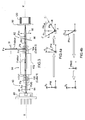
- the figure 3 shows an extended cavity laser source according to the invention.
- a reflection axis rr ' forming the useful laser beam Fu and in a transmitted beam T, along a transmission axis tt' perpendicular to the reflection axis rr '.
- the polarization separator 104 is inclined relative to the axis XX 'of the extended cavity 82 so that its transmission axis tt' is oriented at an angle - ⁇ 1 of opposite sign and of the same value as the rotation angle of polarization ⁇ 1 at the output of the rotator 104, its reflection axis rr 'being oriented from the complementary angle (90- ⁇ 1 ) to 90 degrees.
- the transmitted beam Ftr in the optical path of the cavity is intended to be reflected towards the laser diode DL by the mirror 92 of the cavity forming optical resonances in the cavity extended between the mirror 92 in the extended cavity and the reflecting plate 48 of the cavity. resonator of the DL laser diode.
- the output of the useful beam Fu of the laser source is effected, unlike the sources of the state of the art, laterally along an axis YY 'perpendicular to the axis XX' of the optical path of the beam Fd generated by the laser diode DL in the cavity.
- the polarization rotation angle ⁇ 1 of the beam Frt at the output of the polarization rotator 102 is chosen to be +28 degrees.
- the transmission axis tt 'of the separator of polarization 104 is oriented by -28 degrees and the reflection axis rr 'of 90- ⁇ 1 , ie +62 degrees.
- the reflected beam R is the useful beam Fu coming out laterally of the cavity by an output SI.
- the transmitted beam T in the main direction of the cavity after passing through the standard blade 86 and the cat lens 90e is reflected by the mirror 92 to the laser diode DL.
- the polarizer 100 is a cube 1, for example of a type having a polarization separation plane Pp. Only the 0 degree polarization will be transmitted by the laser beam Fd generated by the laser diode DL in the optical path of the cavity.
- the polarization splitter 104 is another cube 2 having a plane Ps of polarization separation.
- the polarization rotator 102 is a Faraday rotator. In this type of rotator the polarization rotation is a function of the intensity of a magnetic field applied to the rotator.
- the polarizer 100 is an obstruction-type polarizer blocking the Fretour return beam.
- the polarizer 100 is a reflective type polarizer reflecting the Fretour return beam perpendicularly to the transmission axis preventing light Fretour from passing to the laser diode DL
- the Figures 4a and 4b show the polarization of the different laser beams in the extended cavity of the figure 3 .
- the laser diode DL is configured to provide a linear polarization laser beam Fd with a reference polarization angle ⁇ 0 equal to 0 degrees, represented in FIG. figure 4a
- the cube 1 (polarizer 100) is oriented to transmit, along the axis XX 'of the cavity, a beam Fc1 with 100% of this polarization at 0 degrees, reflecting perpendicular to the axis XX' of the optical path of the cavity any part of the beam does not have the same polarization.
- the beam Fc1 with a 0 degree polarization at the output of the cube 1 passes through the polarization rotator 102 producing a rotation of its polarization of + 28 degrees.
- the figure 4a shows the polarization Pfrt of the beam Frt at +28degrees at the output of the rotator 102.
- the beam Frt at the output of the rotator 102 passes into the cube 2 whose test transmission axis is oriented at -28 degrees and the reflection axis R at +62 degrees.
- the intensity transmitted It by the cube 2 will be 30% of the intensity of the beam Frt arriving on the cube 2 and the reflected intensity Ir of 70%.
- the power of the useful beam Fu represents 70% of the beam generated by the laser diode DL which is much greater than the yield of the laser sources of the state of the art using the same laser diode DL.
- the transmitted beam Ftr to the mirror 92 of the extended cavity.
- the transmitted beam Ftr with a polarization of -28 degrees, is reflected by the cavity mirror 92 through the cat-eye lens 90 and the standard plate 86 forms a beam reflected in the cavity Ftrc.
- the reflected beam Ftrc passes through the cube 2 and the Faraday rotator 102.
- the polarization Pftrc of the reflected beam Ftrc in the cavity is turned by +28 by the polarization rotator 102 which is located with a polarization Pftrc0 at 0 degrees (see figure 4b ).
- the beam reflected in the cavity is transmitted by the cube 1, beam Ftrf0 which returns to the laser diode DL with the same polarization at 0 degrees.
- the return beam Fretour reflected by the cube 2 to the laser diode DL on the optical path of the cavity along the axis XX ', passes into the rotator 102 rotating its polarization of +28 degrees.
- the polarization of the return beam Fretour will be its initial polarization of +62 (polarization of the useful beam Fu) increased by the rotation of polarization in the rotator 102 is + 62 + 28 degrees or 90 degrees.
- the cube 1 (polarizer) 100 reflects this return beam perpendicular to the optical path XX 'of the cavity preventing its passage to the laser diode DL.
- the optical device 94 in the extended cavity behaves like a circulator allowing the passage of the beams in multiple back / forth (Fd, Ftrc) in the optical path of the cavity in resonance but isolating the return beams Fretour returning through the output SI of the cavity thus avoiding disturbing the laser diode DL.
- a piezoelectric wedge 120 for the modulation of position of the mirror 92 in the extended cavity can be made from a cube or a solid cylinder having a reflecting face.
- This reflecting face mirror 92 can be made by metallization of one of the faces of the piezoelectric wedge for the reflection of the laser beam in the cavity.
- the piezoelectric wedge 120 no longer needs to include a passage 50 (see figure 2 ) for the useful beam Fu coming out of the cavity.
- a piezoelectric wedge with a high resonant frequency typically of 300 kHz can then be used and allows servocontrol on a large frequency band.
- FIGS. 5a and 5b show a physical embodiment of the compact laser source according to the invention.
- the figure 5a shows the optical elements of the source according to the invention and the figure 5b optical elements mounted in a mechanical support.
- the figure 5a shows, aligned along the axis of the optical path XX 'of the extended cavity 82, the laser diode DL.
- the extended cavity 82 comprises the optical device 94 (not visible on the figure 5a ) the polarization separator 104 of the optical device 94, the calibration blade 86, the cat-eye focusing lens 90 and the piezoelectric wedge 120 with its mirror 92.
- the figure 5b shows the different optical elements of the source according to the invention mounted in a mechanical support 140 ensuring positioning of the optical elements.
- the mechanical support 140 has an output aperture SI for the useful laser beam Fu.
- the useful laser beam Fu exits through the output SI in a direction YY 'perpendicular to the axis XX' of the extended cavity.
- the value of the rotation angle ⁇ 1 of the rotator 102 and therefore the inclination of the transmission axis - ⁇ 1 of the polarization separator 104 can be chosen as a function of the reflected power desired by the polarization separator and therefore the useful power Pu at the output of the laser source.
Landscapes
- Physics & Mathematics (AREA)
- Condensed Matter Physics & Semiconductors (AREA)
- General Physics & Mathematics (AREA)
- Electromagnetism (AREA)
- Optics & Photonics (AREA)
- Semiconductor Lasers (AREA)
- Lasers (AREA)
- Spectrometry And Color Measurement (AREA)
Claims (10)
- Laserquelle mit externem Resonator, die einen nützlichen Laserstrahl (Fu) erzeugt und Folgendes umfasst: wenigstens eine Laserdiode DL (10), die in einem erweiterten optischen Hohlraum (30, 82) montiert ist, der sich zwischen zwei reflektierenden Flächen (92, 48) befindet, die einen optischen Pfad für einen von der Laserdiode DL erzeugten Laserstrahl Fd bilden, ein Modenauswahlfilter (44, 86) in dem optischen Pfad des Hohlraums zum Auswählen einer Resonanzmode aus einem Resonanzmodenkamm des Laserstrahls in dem Hohlraum, einen Polarisationsrotator (102) und einen Polarisationsseparator (104),
dadurch gekennzeichnet, dass der erweiterte Hohlraum (82) in seinem optischen Pfad eine optische Vorrichtung (94) aufweist, die Folgendes umfasst: einen Polarisator (100), der 100% einer geradlinigen Polarisation des von der Laserdiode erzeugten Strahls Fd durchlässt, mit einem Referenzpolarisationswinkel θ0 gleich 0 Grad, wobei der Polarisationsrotator (102) des Strahls am Ausgang des Polarisators (Fc1) einen vorbestimmten Rotationswinkel θ1 hat, wobei der Polarisationsseparator (104) des Strahls (Frt) am Ausgang des Polarisationsrotators in dem Hohlraum so geneigt ist, dass seine Transmissionsachse (tt') in einem Winkel (-θ1) mit dem entgegengesetzten Vorzeichen und demselben Wert geneigt ist wie der Polarisationswinkel des Strahls (Frt) am Ausgang des Rotators (102), wobei die optische Vorrichtung eine Rückkehr eines Reflexionsstrahls (Fretour) des nützlichen Strahls (Fu) zur Laserdiode DL verhindert. - Laserquelle mit externem Resonator nach Anspruch 1, dadurch gekennzeichnet, dass der Polarisationsseparator (104) den Strahl (Frt) am Ausgang des Polarisationsrotators (102) in einen entlang seiner den nützlichen Laserstrahl (Fu) bildenden Reflexionsachse (rr') reflektierten Strahl und in einen entlang einer Transmissionsachse (tt') lotrecht zur Reflexionsachse (rr') transmittierten Strahl (Ftr) spaltet, der dazu bestimmt ist, von einer der beiden reflektierenden Flächen (92) des erweiterten Hohlraums zur Laserdiode DL reflektiert zu werden.
- Laserquelle mit externem Resonator nach Anspruch 1 oder 2, dadurch gekennzeichnet, dass die optische Vorrichtung (94) so konfiguriert ist, dass einerseits der von einer der beiden reflektierenden Flächen (92) des Hohlraums zur Laserdiode DL durch die optische Vorrichtung (94) reflektierte Strahl dieselbe Polarisation bei 0 Grad hat wie der Strahl (Fd) am Ausgang der Laserdiode DL, um die Resonanz in dem erweiterten Hohlraum zu erzeugen, und dadurch, dass andererseits der reflektierte Strahl (Fretour) des über den Ausgang SI der Quelle durch den Polarisationsseparator (104) und den Polarisationsrotator (102) zurückkehrenden nützlichen Strahls (Fu) eine Polarisation lotrecht zur Polarisation des Strahls (Fc1) am Ausgang des Polarisators (100) hat, wobei der Polarisator (100) eine Rückkehr des reflektierten Strahls (Fretour) zur Laserdiode DL verhindert.
- Laserquelle mit externem Resonator nach Anspruch 1 oder 3, dadurch gekennzeichnet, dass sie entlang einer Hauptachse XX' der Ausbreitung des Laserstrahls in dem Hohlraum Folgendes beinhaltet:- eine Laserdiode DL (80), die in einem erweiterten Hohlraum (82) montiert ist, der einen optischen Pfad für einen Laserstrahl (Fd) mit geradliniger Polarisation bildet, mit einem Referenzpolarisationswinkel θ0 von gleich 0 Grad, erzeugt durch die Laserdiode, wobei der erweiterte Hohlraum (82) zwischen zwei reflektierenden Flächen begrenzt wird, wobei ein Spiegel (92) an einem Ende des Hohlraums positioniert ist, der eine erste reflektierende Fläche des Hohlraums bildet, und eine reflektierende Platte (48) des Resonators der Laserdiode DL am anderen Ende des erweiterten Hohlraums (82), die eine zweite reflektierende Fläche bildet,- eine Eingangskollimationslinse (84) des Laserstrahls (Fd) in dem Hohlraum;- eine Etalonplatte (86) zum Auswählen einer Resonanzmode in dem erweiterten Hohlraum;- eine Katzenaugen-Ausgangslinse (90), die den Laserstrahl auf den Spiegel (92) des Hohlraums fokussiert, und- die optische Vorrichtung (94) zwischen der Eingangskollimationslinse (84) und der Etalonplatte (86) (Modenauswahlfilter).
- Laserquelle mit externem Resonator nach Anspruch 1 oder 4, dadurch gekennzeichnet, dass der Rotationswinkel (θ1) der Polarisation des Strahls (Frt) am Rotatorausgang (102) sowie der Winkel der Transmissionsachse (-θ1) des Polarisationsseparators (104) in Abhängigkeit von den gewünschten Intensitäten der transmittierten It und reflektierten Ir Strahlen von dem Polarisationsseparator (104) bestimmt werden, wobei diese Intensitäten definiert werden durch:


- Laserquelle mit externem Resonator nach einem der Ansprüche 1 bis 5, dadurch gekennzeichnet, dass als Wert des Rotationswinkels (θ1) der Polarisation des Strahls (Frt) am Ausgang des Polarisationsrotators (102) +28 Grad gewählt wird, wobei die Transmissionsachse (tt') des Polarisationsseparators (104) in diesem Fall mit -28 Grad und die Reflexionsachse (rr') mit 90-θ1, das heißt mit +62 Grad ausgerichtet ist.
- Laserquelle mit externem Resonator nach einem der Ansprüche 1 bis 6, dadurch gekennzeichnet, dass der Rotator (102) ein Faraday-Rotator ist.
- Laserquelle mit externem Resonator nach einem der Ansprüche 1 bis 7, dadurch gekennzeichnet, dass das Modenauswahlfilter (86) ein Interferenzfilter ist.
- Laserquelle mit externem Resonator nach einem der Ansprüche 1 to 8, dadurch gekennzeichnet, dass sie ein piezoelektrisches Füllstück (120) zum Modulieren der Position des Spiegels (92) im erweiterten Hohlraum aufweist, der von einem massiven Würfel oder Zylinder mit einer reflektierenden Fläche gebildet ist.
- Laserquelle mit externem Resonator nach Anspruch 9, dadurch gekennzeichnet, dass die als Spiegel (92) dienende reflektierende Fläche durch Metallisieren von einer der Flächen des piezoelektrischen Füllstücks erzeugt wird, die zum Reflektieren des Laserstrahls in dem Hohlraum bestimmt ist.
Applications Claiming Priority (2)
| Application Number | Priority Date | Filing Date | Title |
|---|---|---|---|
| FR0703099A FR2915631B1 (fr) | 2007-04-27 | 2007-04-27 | Source laser compacte a faible largeur spectrale. |
| PCT/EP2008/055033 WO2008135404A1 (fr) | 2007-04-27 | 2008-04-24 | Source laser compacte a faible largeur spectrale |
Publications (2)
| Publication Number | Publication Date |
|---|---|
| EP2143181A1 EP2143181A1 (de) | 2010-01-13 |
| EP2143181B1 true EP2143181B1 (de) | 2010-10-20 |
Family
ID=38926144
Family Applications (1)
| Application Number | Title | Priority Date | Filing Date |
|---|---|---|---|
| EP08736560A Not-in-force EP2143181B1 (de) | 2007-04-27 | 2008-04-24 | Kompakte laserquelle mit verringerter spektraler breite |
Country Status (8)
| Country | Link |
|---|---|
| US (1) | US8385376B2 (de) |
| EP (1) | EP2143181B1 (de) |
| JP (1) | JP5433901B2 (de) |
| AT (1) | ATE485612T1 (de) |
| DE (1) | DE602008003115D1 (de) |
| FR (1) | FR2915631B1 (de) |
| RU (1) | RU2457591C2 (de) |
| WO (1) | WO2008135404A1 (de) |
Families Citing this family (8)
| Publication number | Priority date | Publication date | Assignee | Title |
|---|---|---|---|---|
| US9984675B2 (en) | 2013-05-24 | 2018-05-29 | Google Technology Holdings LLC | Voice controlled audio recording system with adjustable beamforming |
| CN106200022B (zh) * | 2016-07-27 | 2019-01-11 | 中国科学院武汉物理与数学研究所 | 一种光纤原子滤光装置 |
| RU2725639C2 (ru) * | 2018-04-09 | 2020-07-03 | Акционерное общество "Российская корпорация ракетно-космического приборостроения и информационных систем" (АО "Российские космические системы") | Перестраиваемый диодный лазер с внешним резонатором |
| RU2683875C1 (ru) * | 2018-04-09 | 2019-04-02 | Акционерное общество "Российская корпорация ракетно-космического приборостроения и информационных систем" (АО "Российские космические системы") | Диодный лазер с внешним резонатором |
| CN111193177A (zh) * | 2018-11-14 | 2020-05-22 | 方砾琳 | 一种激光回光噪声处理系统 |
| CN109596043B (zh) * | 2018-11-29 | 2020-10-30 | 华东师范大学 | 非对称量子干涉仪及方法 |
| JP7364850B2 (ja) * | 2019-04-16 | 2023-10-19 | 日亜化学工業株式会社 | 外部共振器型半導体レーザ |
| CN113655700B (zh) * | 2021-08-19 | 2022-09-13 | 中国计量科学研究院 | 应用于冷原子喷泉钟的小型化主激光光路装置及调整方法 |
Family Cites Families (11)
| Publication number | Priority date | Publication date | Assignee | Title |
|---|---|---|---|---|
| US4088964A (en) * | 1975-01-22 | 1978-05-09 | Clow Richard G | Multi-mode threshold laser |
| SU813570A1 (ru) * | 1978-05-03 | 1985-10-23 | Ордена Трудового Красного Знамени Институт Физики Ан Бсср | Лазер |
| CA1251846A (en) * | 1983-09-26 | 1989-03-28 | Masataka Shirasaki | Laser light source device |
| JPH01303777A (ja) * | 1988-06-01 | 1989-12-07 | Hitachi Ltd | 半導体レーザモジユール |
| SU1616471A1 (ru) * | 1989-02-06 | 1996-02-10 | Институт прикладной физики АН СССР | Лазер |
| US5450427A (en) * | 1994-10-21 | 1995-09-12 | Imra America, Inc. | Technique for the generation of optical pulses in modelocked lasers by dispersive control of the oscillation pulse width |
| US5572358A (en) * | 1994-12-16 | 1996-11-05 | Clark-Mxr, Inc. | Regenerative amplifier incorporating a spectral filter within the resonant cavity |
| US5627848A (en) * | 1995-09-05 | 1997-05-06 | Imra America, Inc. | Apparatus for producing femtosecond and picosecond pulses from modelocked fiber lasers cladding pumped with broad area diode laser arrays |
| JP2001013379A (ja) * | 1999-06-30 | 2001-01-19 | Kyocera Corp | 光モジュール |
| DE60100877T2 (de) * | 2001-05-15 | 2004-09-09 | Agilent Technologies, Inc. (n.d.Ges.d.Staates Delaware), Palo Alto | Optische Anordnung zum Auskoppeln von Licht |
| EP1265324A3 (de) * | 2001-05-15 | 2005-01-19 | Agilent Technologies, Inc. | Laserresonator mit richtungsabhängiger Auskopplung |
-
2007
- 2007-04-27 FR FR0703099A patent/FR2915631B1/fr not_active Expired - Fee Related
-
2008
- 2008-04-24 DE DE602008003115T patent/DE602008003115D1/de active Active
- 2008-04-24 WO PCT/EP2008/055033 patent/WO2008135404A1/fr not_active Ceased
- 2008-04-24 US US12/597,889 patent/US8385376B2/en not_active Expired - Fee Related
- 2008-04-24 RU RU2009143918/28A patent/RU2457591C2/ru not_active IP Right Cessation
- 2008-04-24 EP EP08736560A patent/EP2143181B1/de not_active Not-in-force
- 2008-04-24 JP JP2010504700A patent/JP5433901B2/ja not_active Expired - Fee Related
- 2008-04-24 AT AT08736560T patent/ATE485612T1/de not_active IP Right Cessation
Also Published As
| Publication number | Publication date |
|---|---|
| WO2008135404A1 (fr) | 2008-11-13 |
| ATE485612T1 (de) | 2010-11-15 |
| RU2009143918A (ru) | 2011-06-10 |
| JP5433901B2 (ja) | 2014-03-05 |
| JP2010525594A (ja) | 2010-07-22 |
| EP2143181A1 (de) | 2010-01-13 |
| RU2457591C2 (ru) | 2012-07-27 |
| FR2915631A1 (fr) | 2008-10-31 |
| US8385376B2 (en) | 2013-02-26 |
| FR2915631B1 (fr) | 2009-07-10 |
| US20110038389A1 (en) | 2011-02-17 |
| DE602008003115D1 (de) | 2010-12-02 |
Similar Documents
| Publication | Publication Date | Title |
|---|---|---|
| EP2143181B1 (de) | Kompakte laserquelle mit verringerter spektraler breite | |
| FR2833768A1 (fr) | Laser a resonnateur externe accordable en longueur d'onde utilisant un deflecteur optique | |
| EP1030418B1 (de) | Optischer Reflektor und dessen Benutzung in einem Laser mit externem Resonator | |
| US20130177033A1 (en) | Tunable external resonator laser | |
| FR2658367A1 (fr) | Laser fournissant deux ondes a des frequences differentes. | |
| US7221452B2 (en) | Tunable optical filter, optical apparatus for use therewith and method utilizing same | |
| FR2696286A1 (fr) | Laser à semiconducteur commandé par cavité externe. | |
| FR3056837A1 (fr) | Systeme laser avec retroaction optique | |
| FR2784185A1 (fr) | Dispositif pour l'harmonisation entre une voie d'emission laser et une voie passive d'observation | |
| FR2718256A1 (fr) | Oscillateur paramétrique optique au BBO à largeur de trait étroite utilisant la résonance extraordinaire. | |
| EP0938171B1 (de) | Laserquelle mit kontinuierlich abstimmbarer Wellenlänge | |
| EP1030195B1 (de) | Selbstausrichtendes retroreflektierendes optisches System zur Wellenlängenfilterung und dessen Verwendung in Monochromatoren und Lasern | |
| FR2953945A1 (fr) | Dispositif pour la compensation de la dispersion temporelle appliquee a la generation d'impulsions lumineuses ultra breves. | |
| US20090003403A1 (en) | Wavelength tunable ring-resonator | |
| EP0708509A1 (de) | Einzelnen Wellenlange emittierende Vorrichtung | |
| CA2251486C (en) | External cavity laser type light source | |
| EP1327289B1 (de) | Monomode abstimmbare laserquelle | |
| CN103814488B (zh) | 一种外腔激光器 | |
| EP1031172B1 (de) | Sendeeinrichtung für mikrowellen und anwendung für radar und telekommunikation | |
| WO2012101367A1 (fr) | Cavite laser bifrequences accordable et procede de reglage de la difference de frequence entre une onde ordinaire et une onde extraordinaire d'un laser bifrequences | |
| EP1172906B1 (de) | Optische Anordnung zum Auskoppeln von Licht | |
| US20050094681A1 (en) | Tunable laser source | |
| EP1014110A1 (de) | Lidarsystem und Anwendung in einem Radarsystem | |
| FR2679387A1 (fr) | Laser a effet raman. | |
| WO2010142865A1 (fr) | Source laser comportant un filtre optique auto-accordable a l'interieur du resonateur |
Legal Events
| Date | Code | Title | Description |
|---|---|---|---|
| PUAI | Public reference made under article 153(3) epc to a published international application that has entered the european phase |
Free format text: ORIGINAL CODE: 0009012 |
|
| 17P | Request for examination filed |
Effective date: 20091019 |
|
| AK | Designated contracting states |
Kind code of ref document: A1 Designated state(s): AT BE BG CH CY CZ DE DK EE ES FI FR GB GR HR HU IE IS IT LI LT LU LV MC MT NL NO PL PT RO SE SI SK TR |
|
| GRAP | Despatch of communication of intention to grant a patent |
Free format text: ORIGINAL CODE: EPIDOSNIGR1 |
|
| GRAC | Information related to communication of intention to grant a patent modified |
Free format text: ORIGINAL CODE: EPIDOSCIGR1 |
|
| RIC1 | Information provided on ipc code assigned before grant |
Ipc: H01S 5/14 20060101AFI20100416BHEP |
|
| DAX | Request for extension of the european patent (deleted) | ||
| DAX | Request for extension of the european patent (deleted) | ||
| GRAS | Grant fee paid |
Free format text: ORIGINAL CODE: EPIDOSNIGR3 |
|
| GRAA | (expected) grant |
Free format text: ORIGINAL CODE: 0009210 |
|
| AK | Designated contracting states |
Kind code of ref document: B1 Designated state(s): AT BE BG CH CY CZ DE DK EE ES FI FR GB GR HR HU IE IS IT LI LT LU LV MC MT NL NO PL PT RO SE SI SK TR |
|
| REG | Reference to a national code |
Ref country code: GB Ref legal event code: FG4D Free format text: NOT ENGLISH |
|
| RIN2 | Information on inventor provided after grant (corrected) |
Inventor name: HOLLEVILLE, DAVID Inventor name: DIMARCQ, NOEL |
|
| REG | Reference to a national code |
Ref country code: CH Ref legal event code: EP |
|
| REG | Reference to a national code |
Ref country code: IE Ref legal event code: FG4D Free format text: LANGUAGE OF EP DOCUMENT: FRENCH |
|
| REF | Corresponds to: |
Ref document number: 602008003115 Country of ref document: DE Date of ref document: 20101202 Kind code of ref document: P |
|
| REG | Reference to a national code |
Ref country code: CH Ref legal event code: NV Representative=s name: SERVOPATENT GMBH |
|
| REG | Reference to a national code |
Ref country code: NL Ref legal event code: VDEP Effective date: 20101020 |
|
| LTIE | Lt: invalidation of european patent or patent extension |
Effective date: 20101020 |
|
| PG25 | Lapsed in a contracting state [announced via postgrant information from national office to epo] |
Ref country code: LT Free format text: LAPSE BECAUSE OF FAILURE TO SUBMIT A TRANSLATION OF THE DESCRIPTION OR TO PAY THE FEE WITHIN THE PRESCRIBED TIME-LIMIT Effective date: 20101020 Ref country code: NO Free format text: LAPSE BECAUSE OF FAILURE TO SUBMIT A TRANSLATION OF THE DESCRIPTION OR TO PAY THE FEE WITHIN THE PRESCRIBED TIME-LIMIT Effective date: 20110120 |
|
| REG | Reference to a national code |
Ref country code: IE Ref legal event code: FD4D |
|
| PG25 | Lapsed in a contracting state [announced via postgrant information from national office to epo] |
Ref country code: SE Free format text: LAPSE BECAUSE OF FAILURE TO SUBMIT A TRANSLATION OF THE DESCRIPTION OR TO PAY THE FEE WITHIN THE PRESCRIBED TIME-LIMIT Effective date: 20101020 Ref country code: AT Free format text: LAPSE BECAUSE OF FAILURE TO SUBMIT A TRANSLATION OF THE DESCRIPTION OR TO PAY THE FEE WITHIN THE PRESCRIBED TIME-LIMIT Effective date: 20101020 Ref country code: LV Free format text: LAPSE BECAUSE OF FAILURE TO SUBMIT A TRANSLATION OF THE DESCRIPTION OR TO PAY THE FEE WITHIN THE PRESCRIBED TIME-LIMIT Effective date: 20101020 Ref country code: IS Free format text: LAPSE BECAUSE OF FAILURE TO SUBMIT A TRANSLATION OF THE DESCRIPTION OR TO PAY THE FEE WITHIN THE PRESCRIBED TIME-LIMIT Effective date: 20110220 Ref country code: SI Free format text: LAPSE BECAUSE OF FAILURE TO SUBMIT A TRANSLATION OF THE DESCRIPTION OR TO PAY THE FEE WITHIN THE PRESCRIBED TIME-LIMIT Effective date: 20101020 Ref country code: PT Free format text: LAPSE BECAUSE OF FAILURE TO SUBMIT A TRANSLATION OF THE DESCRIPTION OR TO PAY THE FEE WITHIN THE PRESCRIBED TIME-LIMIT Effective date: 20110221 Ref country code: NL Free format text: LAPSE BECAUSE OF FAILURE TO SUBMIT A TRANSLATION OF THE DESCRIPTION OR TO PAY THE FEE WITHIN THE PRESCRIBED TIME-LIMIT Effective date: 20101020 Ref country code: FI Free format text: LAPSE BECAUSE OF FAILURE TO SUBMIT A TRANSLATION OF THE DESCRIPTION OR TO PAY THE FEE WITHIN THE PRESCRIBED TIME-LIMIT Effective date: 20101020 Ref country code: BG Free format text: LAPSE BECAUSE OF FAILURE TO SUBMIT A TRANSLATION OF THE DESCRIPTION OR TO PAY THE FEE WITHIN THE PRESCRIBED TIME-LIMIT Effective date: 20110120 Ref country code: HR Free format text: LAPSE BECAUSE OF FAILURE TO SUBMIT A TRANSLATION OF THE DESCRIPTION OR TO PAY THE FEE WITHIN THE PRESCRIBED TIME-LIMIT Effective date: 20101020 |
|
| PG25 | Lapsed in a contracting state [announced via postgrant information from national office to epo] |
Ref country code: GR Free format text: LAPSE BECAUSE OF FAILURE TO SUBMIT A TRANSLATION OF THE DESCRIPTION OR TO PAY THE FEE WITHIN THE PRESCRIBED TIME-LIMIT Effective date: 20110121 |
|
| PG25 | Lapsed in a contracting state [announced via postgrant information from national office to epo] |
Ref country code: ES Free format text: LAPSE BECAUSE OF FAILURE TO SUBMIT A TRANSLATION OF THE DESCRIPTION OR TO PAY THE FEE WITHIN THE PRESCRIBED TIME-LIMIT Effective date: 20110131 Ref country code: IE Free format text: LAPSE BECAUSE OF FAILURE TO SUBMIT A TRANSLATION OF THE DESCRIPTION OR TO PAY THE FEE WITHIN THE PRESCRIBED TIME-LIMIT Effective date: 20101020 Ref country code: CZ Free format text: LAPSE BECAUSE OF FAILURE TO SUBMIT A TRANSLATION OF THE DESCRIPTION OR TO PAY THE FEE WITHIN THE PRESCRIBED TIME-LIMIT Effective date: 20101020 Ref country code: EE Free format text: LAPSE BECAUSE OF FAILURE TO SUBMIT A TRANSLATION OF THE DESCRIPTION OR TO PAY THE FEE WITHIN THE PRESCRIBED TIME-LIMIT Effective date: 20101020 |
|
| PLBE | No opposition filed within time limit |
Free format text: ORIGINAL CODE: 0009261 |
|
| STAA | Information on the status of an ep patent application or granted ep patent |
Free format text: STATUS: NO OPPOSITION FILED WITHIN TIME LIMIT |
|
| PG25 | Lapsed in a contracting state [announced via postgrant information from national office to epo] |
Ref country code: RO Free format text: LAPSE BECAUSE OF FAILURE TO SUBMIT A TRANSLATION OF THE DESCRIPTION OR TO PAY THE FEE WITHIN THE PRESCRIBED TIME-LIMIT Effective date: 20101020 Ref country code: SK Free format text: LAPSE BECAUSE OF FAILURE TO SUBMIT A TRANSLATION OF THE DESCRIPTION OR TO PAY THE FEE WITHIN THE PRESCRIBED TIME-LIMIT Effective date: 20101020 Ref country code: DK Free format text: LAPSE BECAUSE OF FAILURE TO SUBMIT A TRANSLATION OF THE DESCRIPTION OR TO PAY THE FEE WITHIN THE PRESCRIBED TIME-LIMIT Effective date: 20101020 Ref country code: PL Free format text: LAPSE BECAUSE OF FAILURE TO SUBMIT A TRANSLATION OF THE DESCRIPTION OR TO PAY THE FEE WITHIN THE PRESCRIBED TIME-LIMIT Effective date: 20101020 |
|
| 26N | No opposition filed |
Effective date: 20110721 |
|
| BERE | Be: lapsed |
Owner name: OBSERVATOIRE DE PARIS Effective date: 20110430 Owner name: THALES Effective date: 20110430 Owner name: CENTRE NATIONAL D'ETUDES SPATIALES Effective date: 20110430 |
|
| REG | Reference to a national code |
Ref country code: DE Ref legal event code: R097 Ref document number: 602008003115 Country of ref document: DE Effective date: 20110721 |
|
| PG25 | Lapsed in a contracting state [announced via postgrant information from national office to epo] |
Ref country code: MC Free format text: LAPSE BECAUSE OF NON-PAYMENT OF DUE FEES Effective date: 20110430 |
|
| PG25 | Lapsed in a contracting state [announced via postgrant information from national office to epo] |
Ref country code: MT Free format text: LAPSE BECAUSE OF FAILURE TO SUBMIT A TRANSLATION OF THE DESCRIPTION OR TO PAY THE FEE WITHIN THE PRESCRIBED TIME-LIMIT Effective date: 20101020 |
|
| PG25 | Lapsed in a contracting state [announced via postgrant information from national office to epo] |
Ref country code: BE Free format text: LAPSE BECAUSE OF NON-PAYMENT OF DUE FEES Effective date: 20110430 |
|
| PG25 | Lapsed in a contracting state [announced via postgrant information from national office to epo] |
Ref country code: LU Free format text: LAPSE BECAUSE OF NON-PAYMENT OF DUE FEES Effective date: 20110424 Ref country code: CY Free format text: LAPSE BECAUSE OF EXPIRATION OF PROTECTION Effective date: 20101020 |
|
| PG25 | Lapsed in a contracting state [announced via postgrant information from national office to epo] |
Ref country code: TR Free format text: LAPSE BECAUSE OF FAILURE TO SUBMIT A TRANSLATION OF THE DESCRIPTION OR TO PAY THE FEE WITHIN THE PRESCRIBED TIME-LIMIT Effective date: 20101020 |
|
| PG25 | Lapsed in a contracting state [announced via postgrant information from national office to epo] |
Ref country code: HU Free format text: LAPSE BECAUSE OF FAILURE TO SUBMIT A TRANSLATION OF THE DESCRIPTION OR TO PAY THE FEE WITHIN THE PRESCRIBED TIME-LIMIT Effective date: 20101020 |
|
| REG | Reference to a national code |
Ref country code: FR Ref legal event code: PLFP Year of fee payment: 9 |
|
| PGFP | Annual fee paid to national office [announced via postgrant information from national office to epo] |
Ref country code: FR Payment date: 20160323 Year of fee payment: 9 |
|
| PGFP | Annual fee paid to national office [announced via postgrant information from national office to epo] |
Ref country code: CH Payment date: 20160411 Year of fee payment: 9 Ref country code: DE Payment date: 20160419 Year of fee payment: 9 Ref country code: GB Payment date: 20160420 Year of fee payment: 9 |
|
| PGFP | Annual fee paid to national office [announced via postgrant information from national office to epo] |
Ref country code: IT Payment date: 20160418 Year of fee payment: 9 |
|
| REG | Reference to a national code |
Ref country code: DE Ref legal event code: R119 Ref document number: 602008003115 Country of ref document: DE |
|
| REG | Reference to a national code |
Ref country code: CH Ref legal event code: PL |
|
| GBPC | Gb: european patent ceased through non-payment of renewal fee |
Effective date: 20170424 |
|
| REG | Reference to a national code |
Ref country code: FR Ref legal event code: ST Effective date: 20171229 |
|
| PG25 | Lapsed in a contracting state [announced via postgrant information from national office to epo] |
Ref country code: FR Free format text: LAPSE BECAUSE OF NON-PAYMENT OF DUE FEES Effective date: 20170502 Ref country code: DE Free format text: LAPSE BECAUSE OF NON-PAYMENT OF DUE FEES Effective date: 20171103 |
|
| PG25 | Lapsed in a contracting state [announced via postgrant information from national office to epo] |
Ref country code: LI Free format text: LAPSE BECAUSE OF NON-PAYMENT OF DUE FEES Effective date: 20170430 Ref country code: CH Free format text: LAPSE BECAUSE OF NON-PAYMENT OF DUE FEES Effective date: 20170430 Ref country code: GB Free format text: LAPSE BECAUSE OF NON-PAYMENT OF DUE FEES Effective date: 20170424 |
|
| PG25 | Lapsed in a contracting state [announced via postgrant information from national office to epo] |
Ref country code: IT Free format text: LAPSE BECAUSE OF NON-PAYMENT OF DUE FEES Effective date: 20170424 |