EP2143392A2 - Chirurgische Dichtelementhalterung zum Halten eines chirurgischen Dichtelements und chirurgisches Abdichtungssystem - Google Patents
Chirurgische Dichtelementhalterung zum Halten eines chirurgischen Dichtelements und chirurgisches Abdichtungssystem Download PDFInfo
- Publication number
- EP2143392A2 EP2143392A2 EP09163064A EP09163064A EP2143392A2 EP 2143392 A2 EP2143392 A2 EP 2143392A2 EP 09163064 A EP09163064 A EP 09163064A EP 09163064 A EP09163064 A EP 09163064A EP 2143392 A2 EP2143392 A2 EP 2143392A2
- Authority
- EP
- European Patent Office
- Prior art keywords
- sealing element
- surgical
- holder
- sealing
- element holder
- Prior art date
- Legal status (The legal status is an assumption and is not a legal conclusion. Google has not performed a legal analysis and makes no representation as to the accuracy of the status listed.)
- Granted
Links
Images






Classifications
-
- A—HUMAN NECESSITIES
- A61—MEDICAL OR VETERINARY SCIENCE; HYGIENE
- A61B—DIAGNOSIS; SURGERY; IDENTIFICATION
- A61B17/00—Surgical instruments, devices or methods
- A61B17/34—Trocars; Puncturing needles
- A61B17/3498—Valves therefor, e.g. flapper valves, slide valves
-
- A—HUMAN NECESSITIES
- A61—MEDICAL OR VETERINARY SCIENCE; HYGIENE
- A61B—DIAGNOSIS; SURGERY; IDENTIFICATION
- A61B17/00—Surgical instruments, devices or methods
- A61B17/34—Trocars; Puncturing needles
- A61B17/3417—Details of tips or shafts, e.g. grooves, expandable, bendable; Multiple coaxial sliding cannulas, e.g. for dilating
- A61B17/3421—Cannulas
-
- A—HUMAN NECESSITIES
- A61—MEDICAL OR VETERINARY SCIENCE; HYGIENE
- A61B—DIAGNOSIS; SURGERY; IDENTIFICATION
- A61B17/00—Surgical instruments, devices or methods
- A61B17/34—Trocars; Puncturing needles
- A61B17/3462—Trocars; Puncturing needles with means for changing the diameter or the orientation of the entrance port of the cannula, e.g. for use with different-sized instruments, reduction ports, adapter seals
- A61B2017/3464—Trocars; Puncturing needles with means for changing the diameter or the orientation of the entrance port of the cannula, e.g. for use with different-sized instruments, reduction ports, adapter seals with means acting on inner surface of valve or seal for expanding or protecting, e.g. inner pivoting fingers
Definitions
- the present invention relates to a surgical sealing element holder for holding a surgical, an expandable insertion opening sealing element of a surgical trocar comprising a trocar sleeve sealing system.
- the present invention relates to a surgical sealing system comprising a trocar with a trocar sleeve and a surgical sealing element holder for holding a surgical, an expandable insertion opening having sealing element.
- a surgical sealing element holder and a surgical sealing system of the type described above are for example from the DE 20 2006 005 442 U1 known.
- Such sealing systems are usually configured wholly or partially reusable.
- sealing units of the sealing systems can lead to increased wear due to the introduction of instruments, so that they can only pass through a limited number of reprocessing cycles, that is, in particular cleaning and subsequent sterilization.
- sealing element holder has a holder sealing element for sealing the sealing element holder with respect to an inner wall surface of the trocar sleeve.
- the support sealing element fluid losses, in particular gas losses, can be prevented by the sealing system in a simple manner.
- An instrument insertion channel defined by the trocar sleeve can thus be optimally sealed, firstly by the retaining seal element and secondly, in particular, by a sealing element inserted into the sealing element holder.
- the sealing element holder also has the advantage that, in particular, wearing parts of the sealing system, for example the sealing element, can be exchanged in a simple manner.
- the bracket sealing element can also ensure a play-free fixation of the sealing unit in the trocar or a sealing housing thereof. Furthermore, manufacturing tolerances of the sealing element holder and / or the trocar sleeve can be easily and reliably compensated by the holder sealing element.
- the sealing element holder is designed for releasable connection to the trocar sleeve. This allows the sealing element holder with a sealing element arranged thereon, fast, easy and safe exchange.
- the sealing element holder becomes particularly simple in design and in production when the holder sealing element is designed in the form of a flange projecting in the radial direction from the sealing element holder.
- the bracket sealing element can thus be integrated directly into the sealing element holder.
- Manufacturing tolerances can be compensated for particularly well by the sealing element holder if the flange is inclined somewhat pointing in the distal direction relative to a plane extending transversely to a longitudinal axis of the sealing element holder.
- An inclination angle may be in a range of 1 ° to 15 °, preferably in a range of 1 ° to 8 °.
- the flange can thus be deformed somewhat in the proximal direction after application to a corresponding sealing surface of the trocar sleeve and can thus press against the sealing surface in particular under prestress in order to ensure a permanent seal.
- the compensation of manufacturing tolerances on the trocar sleeve and / or the sealing element holder can be achieved in a simple manner.
- the sealing element holder can be produced in a particularly simple and cost-effective manner if the holder sealing element is formed integrally with the sealing element holder.
- the sealing element holder can be made for example of a plastic by injection molding in one step.
- the holder sealing element is at least partially elastically deformable.
- manufacturing tolerances can be compensated in a simple manner.
- a flexible, axially slightly resilient embodiment of the Garrungsêtlements Under a sectionwise elastic deformability is to be understood in particular a deformability along a part of a radial extent of the support sealing element.
- the holder sealing element carries a further seal.
- the further seal is arranged such that it bears against a corresponding sealing surface of the trocar sleeve when the sealing element holder is connected to the trocar sleeve.
- the further seal is permanently connected to the retaining seal element.
- the further seal is integrally formed on the mounting seal element, in particular molded. In this way, the sealing element holder can be easily and inexpensively manufactured.
- a particularly good and secure seal between the sealing element holder and the trocar sleeve can be achieved if the further seal is made of an elastomer.
- the sealing element holder of the sealing system is one of the sealing element holders described above. With such a sealing element holder, the handling and operation of the sealing system improve overall in the manner described above in each case.
- the sealing element holder is detachably connectable to the trocar sleeve.
- the sealing element holder which in particular a surgical sealing element can be held to easily detach from the trocar sleeve in the event of wear or damage which has occurred on the sealing element or the sealing element holder.
- the trocar sleeve has a sealing element holder receptacle for inserting the sealing element holder. It is thus possible to assemble the parts of the sealing system simply and safely and, if necessary, replace them again.
- a sealing of the sealing element holder can be achieved relative to the trocar sleeve, when the holder sealing element rests against a in proximal or substantially in the proximal direction facing annular surface of the trocar sleeve.
- Such a one-handed operation is not possible, especially when acting in the radial direction sealing elements, for example, when pushed onto an outer surface of the sealing element holder sealing rings.
- the annular surface carries an additional seal.
- the additional seal is arranged such that it bears against the holder sealing element when the sealing element holder is connected to the trocar sleeve.
- the additional seal is permanently connected to the annular surface.
- the additional seal is to the bracket sealing element molded, in particular molded. In this way, the trocar can be easily and inexpensively manufactured.
- a particularly good and secure seal between the sealing element holder and the trocar sleeve can be achieved if the additional seal is made of an elastomer.
- the diameter taper may be formed towards a distal end of the trocar sleeve.
- it may also be gradual or continuous and inclined to a plane transverse to the longitudinal axis of the trocar sleeve, for example an angle of inclination in a range of 10 ° to 80 °, preferably 30 ° to 60 °.
- the sealing system has a sealing element on the holding a surgical, an expandable insertion having sealing element for sealing the insertion opening during insertion of a surgical instrument.
- the sealing system comprises a surgical protective device for the sealing element, which protective device can be arranged on the trocar or on a part thereof, annularly closed or substantially annularly closed and having an opening with several circumferentially arranged and parallel or on a protective device which points towards the longitudinal axis of the protective device, which protective elements have substantially free ends pointing in the distal direction, wherein at least one part have the protective elements at their free ends or in the region of their free ends on its outer side at least one retaining element for engaging with the sealing element.
- the protective elements of the protective device can cover an inner surface of the sealing element substantially completely, so that when inserting an instrument into the trocar sleeve, the instrument initially comes into contact with the protective elements and expands them if necessary, in which case the protective elements make contact with the sealing element and expand it can.
- injuries or damage to the sealing element can be avoided by introduced into the trocar sleeve instruments.
- the provision of retaining elements on at least some of the protective elements has the advantage that targeted locking of the protective device with the sealing element can occur, which is just to be avoided when inserting an instrument.
- bringing the retaining elements into engagement with the sealing element has the advantage of ensuring that the sealing element is protected up to the area of the sealing element which rests against the inserted instrument shaft, ie in particular a defined sealing line or sealing lip can be.
- a widening of the insertion opening of the protective device automatically also leads to an expansion of the sealing element.
- a relative movement of the protective device and the sealing element is substantially prevented. This has the advantage that from the engagement of the retaining elements with the sealing element predetermined covering the same in the axial direction of the protective device can be ensured independently of an insertion position of the listed instrument.
- a bringing into engagement can take place, in particular, if the retaining element has a minimum diameter, so that when it hits, for example, a sealing element made of an elastomer, its wall can bulge and thus virtually define a corresponding recess into which the retaining element intervenes. However, the bulging will cause the sealing element to slide along buckling article prevents the sealing element.
- a single retaining element is provided on the respective protective elements.
- the at least one retaining element is designed in the form of a retaining projection protruding from the respective protective element.
- Such retaining elements are particularly easy to manufacture and can be dimensioned accordingly to ensure a targeted hooking or otherwise engaging the retaining projections with the sealing element.
- retaining projections project perpendicularly or substantially perpendicularly from the protective elements.
- a configuration of the retaining projections is particularly easy to manufacture. Hooking or engaging the retaining projections with the sealing element can be improved, in particular when the protective elements protrude parallel to a longitudinal axis defined by the sealing element on the base body, if at least a portion of the retaining projections obliquely relative to an extension of the protective elements in the region of their free ends pointing away from them.
- such retaining projections have away from the base body and outwardly in the direction of the sealing element.
- a trocar system generally designated by reference numeral 10, forming a surgical sealing system is shown. It comprises a trocar sleeve 14 defining a longitudinal axis 12 with a seal housing 16 and a shaft 18 extending distally therefrom, a seal assembly 20 disposed in the seal housing 16, and an obturator 22 which is a distal end shaped specifically for severing and expanding body tissue and is inserted into the trocar sleeve 14 prior to insertion of the trocar sleeve 14 into a patient's body to facilitate insertion of the trocar sleeve 14 into the patient's body.
- the trocar sleeve 14 is formed substantially rotationally symmetrical and defined in the interior of the seal housing 16 a receptacle 24 for the seal assembly 20.
- a minimum inner diameter of the trocar sleeve 14 is defined by the shaft 18.
- a first transition region 26 from the shaft 18 to the seal housing 16 expands the Inner diameter of the shaft 18 continuously and remains constant in the region of a first extension space 28.
- a second transition region 30 adjoins the first expansion space 28, in which the inner diameter of the trocar sleeve 14 is continuously expanded again up to a distal part 32 of the receptacle 24.
- An inner diameter of the seal housing 16 expands in one stage during the transition from the distal part 32 to a proximal part 34 thereof, so that an annular surface 36 pointing in the proximal direction is defined.
- the annular surface may optionally carry an additional seal 37, which is produced by injection molding of an elastomer and exemplified in FIG. 3 dotted is marked.
- a flat recess 38 in the annular surface thus defines a planar sealing surface 40 protruding slightly in the proximal direction, which is separated from an inner wall 42 of the proximal part 34 by the recess 38.
- two mutually symmetrical locking receptacles 46 are formed, each having two lateral undercuts 48, which are open in opposite directions in the circumferential direction.
- the locking receptacles 46 form part of a latching connection, with which the seal assembly 20 can be locked in the seal housing 16, as will be explained in detail below.
- a slightly tapered recess 50 formed symmetrically between the locking receptacles 46, in which a corresponding projection 250 of the obturator 22 engages when the obturator 22 completely inserted into the trocar sleeve 14 is like this in FIG. 12 is shown.
- a connecting piece 54 is integrally formed in the region of the second transition region 30 on one side, which defines a channel 56 extending perpendicularly to the longitudinal axis 12. Inserted into the channel 56 is a connection piece 57 of a closure element 58 with a standardized Luer-lock connection 60 protruding in the opposite direction.
- the closure element 58 comprises a cylindrical valve housing 62, in which a correspondingly formed cylindrical closure piston 64 is inserted with an integrally formed actuating lever 66.
- the closure piston 64 is provided with a bore 68, so that depending on a rotational position of the closure piston 64 relative to the valve housing 62, the channel 56 can be opened or closed for fluids.
- any other types of known closure elements may be provided, in particular also special, spring-loaded and thus self-closing luer-lock connections.
- the seal assembly 20 includes two seals, namely a Phillips valve 70, which is held on a retaining ring 72, and a sealing element 74, which in its basic structure in the German utility model 20 2006 005 442 is described in detail. The description therein is hereby incorporated in full in the present description.
- the sealing element 74 is held in the interior of a sealing element holder 76, which is detachably connectable to the retaining ring 72.
- a protective device 78 is releasably held on the sealing element 74, so that the sealing element 74 can be removed together with the protection device 78 if necessary from the sealing element holder 76.
- Proximal lake the sealing element holder 76 can still be closed with a lid 80.
- the retaining ring 72 comprises a circular cross-section ring 82, from the proximal-side edge of a protruding in the proximal direction annular flange 84 is formed, which does not extend over an entire width of a wall of the ring 82, but only about half.
- connecting wings 86 are each other, relative to the longitudinal axis 12, diametrically opposite in the proximal direction.
- the connecting wings 86 each have two substantially rectangular apertures 88, which are oriented transversely to the longitudinal axis 12.
- the connecting wings 86 are arranged slightly spaced from the flange 84, so that in each case a groove 90 is formed between the flange 84 and the connecting wings 86.
- the cross-slot valve 70 includes an annular mounting flange 92 on the proximal side, which carries a distally facing annular projection 94, which is formed in its height and in its outer dimensions corresponding to the grooves 90.
- the cross-slot valve 70 further includes a valve body 96 projecting distally on the attachment flange 92, which opens distally into a cross-shaped end face 98 which is provided with two mutually perpendicular slots 100.
- the valve body 96 is in a basic position, as for example in the Figures 2 and 4 is formed so formed that the separated by the slots 100 cut surfaces 102 of the valve body 96 abut directly against each other and so completely close a defined by the mounting flange 92 annular opening 104 slightly distal side of the mounting flange 92.
- the valve body 96 is formed on the proximal side directly to an inner edge of the mounting flange 92, so that between the valve body 96 and the annular projection 94, an annular groove 106 is formed, in which the flange 84 can engage substantially form-fitting manner.
- the mounting flange 92 is further provided with two radially facing recesses 108, in which the connecting wings 86 engage when the valve body 96 is inserted into the retaining ring 72 and at least partially with the valve body 96, in particular with its slots 100 having end face 98, projects beyond a distal edge of the ring 82.
- the sealing element holder 76 is formed substantially elongated sleeve-shaped. It comprises a central, coaxially with the longitudinal axis 22 formed sleeve body 110. An inner surface 112 of the sleeve body 110 is formed completely rotationally symmetrical. The inner surface 112 defines and defines a longitudinal channel 114 in which the sealing element 74 is inserted. An inner diameter of the sleeve body 110 widens slightly toward the distal and proximal ends thereof, respectively. On the distal side and on the proximal side, ring-shaped annular projections 116 and 118, which point in the proximal or distal direction, are designed to engage with corresponding flanges or grooves on the sealing element 74.
- the sleeve body 110 On an outer side of the sleeve body 110 are slightly proximal to the distal side annular projection 118 two relative to the longitudinal axis 12 diametrically opposed and pointing in opposite directions locking lugs 120 which outwardly facing, slightly distally inclined sliding surfaces 122 and thus also in the proximal direction define facing annular edge 124.
- the latching lugs 120 are formed corresponding to the openings 88 on the connecting wings 86.
- the connecting wings 86 can be pushed over the sliding surfaces 122 coming from distally so that they pivot outward in the radial direction away from the longitudinal axis 12. Once the detents 120 can fully engage in the openings 88, the connecting wings 86 spring back in the direction of the longitudinal axis 12 back. In the manner described, the retaining ring 72 and the sealing element holder 76 can be locked together.
- two coupling members 126 are disposed diametrically opposite one another from an outer side of the sealing element holder 76. They each comprise a transverse web 128 protruding directly from the sleeve body 110 in the radial direction, from which a spring part 130 extending substantially parallel to the sleeve body 110 in the proximal direction extends away. At a proximal end of the spring part 130 on both sides of the spring part 130 substantially in the circumferential direction facing and protruding locking projections 132 are formed, each of which from the longitudinal axis 12 facing away sliding surfaces 134 define. Between the sliding surfaces 134, an essentially cuboidal operating element 136 is arranged on an outer side of the spring parts 130, which protrudes slightly beyond the end of the spring part 130 on the proximal side.
- the distal end of the sealing element holder 76 is inserted into the seal housing 16 until the undercuts 46 laterally delimiting projections 49 come into contact with the sliding surfaces 134 and the spring parts 130 due to the sliding something in the direction of the Swivel longitudinal axis 12 towards.
- the spring parts 130 spring slightly outward in the radial direction and the end face 130 lies on a distal one Direction facing edge of the projection 49 on.
- the control elements 136 can be acted upon by a force acting in the direction of the longitudinal axis 12, so that the spring parts 130 are pivoted in the direction of the longitudinal axis 12 and the locking projections 132 release the undercut 48 again.
- the sealing element holder 76 can then be pulled out of the seal housing 16 in the proximal direction.
- a retaining seal element 140 is formed, in the form of a substantially radially projecting annular flange, which is slightly inclined in the distal direction, by about 2 ° relative to a transverse to the longitudinal axis 12 transverse plane.
- the holder sealing element 140 has a thickness which predetermines a certain elasticity or flexibility of the holder sealing element 140. It can thus somewhat feather in the axial direction and compensate for manufacturing tolerances on the trocar sleeve 14 and the sealing element holder 76.
- the retainer seal member 140 is disposed on the seal member retainer 76 such that when the retainer retainer 76 is latchingly connected to the seal housing 16 in the manner described, a distal facing seal surface 142 of the seal retainer 76 abuts the annular surface 36, optionally biased slightly and thus a perfect sealing of the sealing element holder 76 relative to an inner wall 144 of the sealing housing 16 of the trocar sleeve is achieved.
- the support seal member 140 can optionally support a further seal 141 for improving a sealing effect, which is produced by injection molding of an elastomer and exemplified in FIG. 11 dotted is marked.
- the sealing element 74 is formed with respect to the longitudinal axis 12 is substantially rotationally symmetrical. Further, it is formed with respect to a transverse to the longitudinal axis extending opening plane 146 substantially mirror-symmetrical.
- the opening plane 146 is parallel to two two-sided Flange rings 148 which limit the sealing element 74 distally and proximally and define a maximum outer diameter of the sealing element 74.
- Of the flange rings 148 are at most far outward on them and in each case in the direction of the other flange ring 148 out facing annular projections 150 from which the ring projections 116 and 118 can engage around the outside.
- the sealing element 74 can thus be suspended or tensioned in a simple manner via the annular projections 116 and 118 and held in the interior of the sealing element holder 76.
- first transverse portion 152 which merges into a first, outwardly bent back first bead portion 154, which in turn merges directly into a second bead portion 156, which in turn on the longitudinal axis 12 back having directed end.
- the second bead portion 156 thus defines an annular groove 158 opened in the direction of the longitudinal axis.
- a short cylindrical section 160 which merges into a thickened bead 162 protruding outside on the sealing element 74.
- the wall 164 folds like a curtain up to the opening plane 146.
- the folding creates a sealing line 166, which defines in the form of a wavy line wave peaks 170 on the proximal side of the opening plane 146 and wave troughs 172 on the distal side of the opening plane 146.
- the wavy line 168 is slightly reinforced and formed in the form of a sealing lip 174, which is thus located partially proximal and partially distal side of the opening plane 146.
- the sealing line 166 and thus also the sealing lip 174 delimit an annular opening 176 of the sealing element 74.
- the opening 176 has in a basic position, as for example in the FIGS. 3 to 6 is shown, a minimum Inside diameter.
- the opening 176 may, as in FIG. 11 are expanded so far that an inner diameter thereof corresponds to an inner diameter of the sealing element 74 in the region of the beads 162.
- the folded wall 164 unfolds, is virtually completely folded over the entire length between the beads 162 and thus defines a substantially cylindrical wall surface.
- reinforcing ribs 178 reaching from the beads 164 to the sealing lip 166 are formed on an outer side of the wall 164.
- the sealing element 74 is molded in one piece as a whole from a plastic, which preferably has elastomeric properties.
- two, diametrically opposite recesses 180 are provided on the flange rings 148, which are formed corresponding to two in the radial direction of the sealing element holder 76 in the direction of the longitudinal axis 12 projecting projections 182.
- the recesses 180 in conjunction with the projections 182 form an anti-rotation, so that the sealing element 74 and the sealing element holder 76 in an example in the Figures 2 and 3 Assembly position not shown about the longitudinal axis 12 are rotatable relative to each other.
- the sealing element holder 76 After loading the retaining ring 72 with the Phillips valve 70, the sealing element holder 76, in which the sealing element 74 is inserted in the manner described above, are connected to the retaining ring 72. On the distal side, a distally facing annular end surface 184 of the sealing member 74 forms a locating surface for the mounting flange 92.
- the mounting flange 92 and the flange ring 148 are pressed against each other to form a perfect one Seal.
- the protective device 78 comprises an annular, self-contained base body 190, which defines a circular opening 192. From the main body 190, a ring projection 196 protrudes outward in the radial direction and adjacent to a proximal end 194. A little further distal side, the connecting elements 188 are arranged in the form of short web-like projections.
- the base body 190 can thus be mounted directly on the sealing element 74, for which purpose the connecting elements 188 engage positively in the depressions 168. They thus simultaneously form an anti-rotation of the protective device 78 relative to the sealing element 74. Furthermore, they also form a positioning aid of the protective device 78 relative to the sealing element 74th
- a total of 10 in each case five lamellar short protective elements 200 and five long protective elements 202 extend in the distal direction. They point in longitudinal section, as in FIG. 8 shown, a constant over its entire length thickness.
- the short protective elements 200 are essentially the same width up to their free end 204
- the long protective elements 202 are approximately the same length as the short protective elements 200, but then a width of the long protective elements 202 clearly decreases towards its distal end 206, so that a narrow protective element section 208 is formed, which is formed in its outer contour substantially corresponding to a wave trough 172.
- the long protective elements 202 each carry a retaining element 212 projecting from an outer side 210 slightly inclined in the distal direction and having a length of less than 1 mm.
- the retaining element has a substantially frusto-conical shape and has a rounded tip 214.
- the protective elements 200 and 202 which are flexible due to their small thickness, fold in the direction of the longitudinal axis 12 and engage in the FIGS. 6 to 8 shown position.
- the long protective elements 202 extend distally from the edge 198 on the distal side of the connecting elements 188, the short protective elements 200 in the regions of the edge 198 to which no connecting element 188 corresponds.
- the protective device 78 can be connected in the correct position with the sealing element 74, this means that in a basic position all five protective element sections 208 dive into corresponding wave troughs 172. This ensures that the distal ends 204 and 206 of the protective device 78 practically reach as far as the sealing line 166 and substantially completely cover an inner wall surface 216 of the sealing element 74.
- the protective elements 200 and 202 are in the mounted basic position already slightly distal side of the bead 162 from the wall surface 216 from and touch them at most near their ends 204 and 206. In the basic position, the protective elements 200 and 202 are arranged overlapping each other, wherein the short protective elements 200th As a result, only the retaining elements 212 adjacent to the sealing line 166 touch the wall 164 of the sealing element 74.
- the obturator 22 coming from proximal introduced into the sealing element 74, so it first comes in contact with inner surfaces of the short protective elements 200. If an outer diameter, as is the case with the obturator 22 of an instrument greater than the opening 176, then the short protective elements 200 are pressed against the long protective elements 202 and pivoted outwardly. In this case, the retaining elements 212 are pressed with their tips 214 in the wall 164 of the sealing element 74. This results in a bulge 218 of the wall 164 by the retaining elements 212, so that they get caught in the wall 164, it can also be said, the retaining elements 212 and the sealing element 74 are engaged with each other.
- the distal ends 206 of the long protective elements 202 Due to the hooking of the retaining elements 212 in the wall 164, a relative movement of the distal ends 206 of the long protective elements 202 relative to the sealing element 74 is virtually prevented. Regardless of a widening or unfolding of the wall 164 as a function of a diameter of the inserted instrument, the distal ends 206 of the long protective elements 202 always extend to the sealing line 166 and protect the sealing element 74 from the possible damage described at the beginning as a result of the wall coming into contact 164 with sharp edges of the inserted instruments.
- the Verhake bin of the retaining elements 212 is maintained.
- a connecting device 220 formed by the recesses 186 and the connecting elements 188 a tilting of the instrument shaft initially resting against the protective device is transmitted directly to the sealing element 74, specifically in the region of the bead 162, so that the sealing element 74 is analogous to a tilting of the protective device 78 is tilted with.
- the special arrangement of the protective device 78 on the sealing element 74 thus also forms, as it were, a tilt adjustment in the introduction of instruments.
- the first bead section 154 which has both a tilting movement and a transverse movement, at least as far as the first bead section, is particularly suitable for this purpose 154 is spaced from an inner wall of the sealing element holder 76 allowed.
- the cover 80 also has two pointing in the distal direction, opposing tabs 228 which have locking projections 230 at free ends, which can be brought into engagement with corresponding, not shown in the figures locking edges on the sealing element holder 76.
- the lid 80 can then be snapped onto the sealing element holder 76 in a simple manner after mounting the sealing element holder 76 on the seal housing 16.
- the obturator 22 is provided. It comprises a hollow shaft 232 extending coaxially with the longitudinal axis 12, which continuously tapers in a distal end region 234 in its outer diameter and defines a rounded tip 236.
- the end portion 234 is not circular in cross-section at any point, but formed in sequence of defined, parallel to the longitudinal axis 12 extending recesses 238 asymmetrically.
- each Retaining projections 242 arranged offset from one another by 90 ° are provided, which serve to support and connect a cover 244 which essentially has the shape of a hemisphere.
- a cover 244 which essentially has the shape of a hemisphere.
- projections 246 are formed on an inner side.
- the lid 244 may also be screwed or glued to the shaft 232 and its retaining projections 242.
- the obturator 22 can be used with a defined orientation with respect to the longitudinal axis 12 in the trocar sleeve 14. If the obturator 22 is inserted completely into the trocar sleeve 14, the distal end region 234 projects beyond an end surface 252 of the shaft 18 which is inclined by approximately 45 ° with respect to the longitudinal axis 12, as shown in FIG FIG. 12 is shown.
- the phillips valve 70 is first formed by means of a distal end of an instrument or, for example, the tip 236 of the obturator 22 can be opened when the insertion of an instrument whose shaft, for example, the shaft 232 of the obturator 22, by means of the sealing lip 144 of the sealing element 74 is sealed. This ensures that either the cross-slot valve 70 is closed or a seal by means of the sealing element 74 relative to the imported instrument.
- the trocar sleeve 14, the retaining ring 72, the cross-slot valve 70, the sealing element 74, the protection device 78, the sealing element holder 76 and the cover 80 are each formed in one piece and preferably injected from a sterilizable plastic material.
- the obturator 22 is formed in two parts as described and may also be made of a plastic material by injection molding.
- a gas or a liquid can be introduced or removed through the shaft 18 into the interior of a patient's body via the closure element 58, even if an instrument, for example the obturator 22, is inserted into the trocar sleeve 14 and a through the Trocar sleeve 14 defined channel on the proximal side of the connecting piece 54 is sealed.
Landscapes
- Health & Medical Sciences (AREA)
- Surgery (AREA)
- Life Sciences & Earth Sciences (AREA)
- Biomedical Technology (AREA)
- Nuclear Medicine, Radiotherapy & Molecular Imaging (AREA)
- Engineering & Computer Science (AREA)
- Pathology (AREA)
- Heart & Thoracic Surgery (AREA)
- Medical Informatics (AREA)
- Molecular Biology (AREA)
- Animal Behavior & Ethology (AREA)
- General Health & Medical Sciences (AREA)
- Public Health (AREA)
- Veterinary Medicine (AREA)
- Surgical Instruments (AREA)
Abstract
Description
- Die vorliegende Erfindung betrifft eine chirurgische Dichtelementhalterung zum Halten eines chirurgischen, eine erweiterbare Einführöffnung aufweisenden Dichtelements eines chirurgischen, einen Trokar mit einer Trokarhülse umfassenden Abdichtungssystems.
- Ferner betrifft die vorliegende Erfindung ein chirurgisches Abdichtungssystem umfassend einen Trokar mit einer Trokarhülse und eine chirurgische Dichtelementhalterung zum Halten eines chirurgischen, eine erweiterbare Einführöffnung aufweisenden Dichtelements.
- Eine chirurgische Dichtelementhalterung sowie ein chirurgisches Abdichtungssystem der eingangs beschriebenen Art sind beispielsweise aus der
DE 20 2006 005 442 U1 bekannt. Derartige Abdichtungssysteme sind üblicherweise ganz oder teilweise wiederverwendbar ausgestaltet. Insbesondere bei Dichteinheiten der Abdichtungssysteme kann es zu einem erhöhten Verschleiß aufgrund des Einführens von Instrumenten kommen, so dass diese nur eine begrenzte Zahl von Wiederaufbereitungszyklen, das heißt insbesondere Reinigung und nachfolgende Sterilisation, durchlaufen können. Insbesondere bei nur teilweise wiederverwendbaren Systemen ist es wichtig, dass das Dichtelement auf einfache und sichere Weise ausgetauscht und ein von der Trokarhülse definierter Kanal sicher gegen Gasverlust abgedichtet werden kann. - Es ist daher Aufgabe der vorliegenden Erfindung, eine chirurgische Dichtelementhalterung und ein chirurgisches Abdichtungssystem der eingangs beschriebenen Art so zu verbessern, dass ein Dichtelement des Abdichtungssystems einfach und sicher ausgewechselt werden und eine jederzeit perfekte Abdichtung gegenüber einem Kanal der Trokarhülse gewährleistet ist.
- Diese Aufgabe wird bei einer chirurgischen Dichtelementhalterung sowie einem chirurgischen Abdichtungssystem der eingangs beschriebenen Art erfindungsgemäß dadurch gelöst, dass die Dichtelementhalterung ein Halterungsdichtelement zum Abdichten der Dichtelementhalterung mit Bezug zu einer inneren Wandfläche der Trokarhülse aufweist.
- Durch das Halterungsdichtelement können auf einfache Weise Fluidverluste, insbesondere Gasverluste, durch das Abdichtungssystem hindurch verhindert werden. Ein durch die Trokarhülse definierter Instrumenteneinführkanal kann so optimal abgedichtet werden, zum einen durch das Halterungsdichtelement und zum anderen insbesondere durch ein in die Dichtelementhalterung eingesetztes Dichtelement. Die Dichtelementhalterung hat ferner den Vorteil, dass insbesondere Verschleißteile des Dichtungssystems, beispielsweise das Dichtelement, auf einfache Weise ausgetauscht werden können. Das Halterungsdichtelement kann zudem eine spielfreie Fixierung der Dichteinheit in der Trokarhülse oder einem Dichtungsgehäuse derselben sicherstellen. Des Weiteren lassen sich Fertigungstoleranzen der Dichtelementhalterung und/oder der Trokarhülse durch das Halterungsdichtelement einfach und sicher ausgleichen. Es werden keine weiteren Dichtungselemente benötigt, um die Dichtelementhalterung relativ zur Trokarhülse abzudichten. Dies vereinfacht sowohl die Montage als auch die Demontage der Dichtelementhalterung von der Trokarhülse. Des Weiteren können so auch Kosten des Abdichtungssystems insgesamt reduziert werden, da beispielsweise das Halterungsdichtelement direkt in die Dichtelementhalterung integriert werden kann.
- Günstigerweise ist die Dichtelementhalterung ausgebildet zum lösbaren Verbinden mit der Trokarhülse. Dies gestattet es, die Dichtelementhalterung mit einem daran angeordneten Dichtelement, schnell, einfach und sicher auszutauschen.
- Besonders einfach in der Konstruktion sowie in der Herstellung wird die Dichtelementhalterung, wenn das Halterungsdichtelement in Form eines in radialer Richtung von der Dichtelementhalterung abstehenden Flansches ausgebildet ist. Das Halterungsdichtelement lässt sich so direkt in die Dichtelementhalterung integrieren.
- Besonders gut lassen sich Fertigungstoleranzen durch die Dichtelementhalterung ausgleichen, wenn der Flansch etwas in distaler Richtung weisend bezogen auf eine quer zu einer Längsachse der Dichtelementhalterung verlaufende Ebene geneigt ist. Ein Neigungswinkel kann in einem Bereich von 1° bis 15° liegen, vorzugsweise in einem Bereich von 1° bis 8°. Zum Abdichten kann so der Flansch nach Anlegen an eine entsprechende Dichtfläche der Trokarhülse etwas in proximaler Richtung verformt werden und kann so insbesondere unter Vorspannung gegen die Dichtfläche drücken, um eine dauerhafte Abdichtung sicherzustellen. Auch der Ausgleich von Fertigungstoleranzen an der Trokarhülse und/oder der Dichtelementhalterung kann so auf einfache Weise erreicht werden.
- Besonders einfach und kostengünstig herstellen lässt sich die Dichtelementhalterung, wenn das Halterungsdichtelement einstückig mit der Dichtelementhalterung ausgebildet ist. Die Dichtelementhalterung kann so beispielsweise aus einem Kunststoff durch Spritzgießen in einem Arbeitsschritt hergestellt werden.
- Vorteilhafterweise ist das Halterungsdichtelement mindestens abschnittsweise elastisch verformbar. Insbesondere können so Fertigungstoleranzen auf einfache Weise ausgeglichen werden. Günstig ist auch eine flexible, axial etwas federnde Ausgestaltung des Halterungsdichtelements. Unter einer abschnittsweisen elastischen Verformbarkeit ist insbesondere eine Verformbarkeit längs eines Teil einer radialen Erstreckung des Halterungsdichtelements zu verstehen.
- Günstig ist es, wenn das Halterungsdichtelement eine weitere Dichtung trägt. Insbesondere dann, wenn das Halterungsdichtelement selbst nur wenig oder gar nicht elastisch oder flexibel ausgebildet ist, ermöglichst es die weitere Dichtung, eine optimale Abdichtung relativ zur Trokarhülse zu realisieren. Vorzugsweise ist die weitere Dichtung derart angeordnet, dass sie an einer korrespondierenden Dichtfläche der Trokarhülse anliegt, wenn die Dichtelementhalterung mit der Trokarhülse verbunden ist.
- Vorteilhaft ist es, wenn die weitere Dichtung mit dem Halterungsdichtelement unlösbar verbunden ist. Auf diese Weise wird es insbesondere möglich, die Dichtelementhalterung mit nur einer Hand mit der Trokarhülse zu verbinden oder von dieser zu lösen. Vorzugsweise ist die weitere Dichtung an das Halterungsdichtelement angeformt, insbesondere angespritzt. Auf diese Weise kann die Dichtelementhalterung einfach und kostengünstig hergestellt werden.
- Eine besonders gute und sichere Abdichtung zwischen der Dichtelementhalterung und der Trokarhülse kann erreicht werden, wenn die weitere Dichtung aus einem Elastomer hergestellt ist.
- Besonders vorteilhaft ist es, wenn die Dichtelementhalterung des Abdichtungssystems eine der oben beschriebenen Dichtelementhalterungen ist. Mit einer solchen Dichtelementhalterung verbessern sich die Handhabung und Bedienung auch des Abdichtungssystems insgesamt in der jeweils oben beschriebenen Weise.
- Vorzugsweise ist die Dichtelementhalterung mit der Trokarhülse lösbar verbindbar. Dies ermöglicht es, die Dichtelementhalterung, an welcher insbesondere ein chirurgisches Dichtelement gehalten werden kann, bei einem am Dichtelement oder der Dichtelementhalterung aufgetretenen Verschleiß oder einer Beschädigung auf einfache Weise von der Trokarhülse zu lösen.
- Vorzugsweise weist die Trokarhülse eine Dichtelementhalterungsaufnahme auf zum Einsetzen der Dichtelementhalterung. Es ist so möglich, die Teile des Abdichtungssystems einfach und sicher zusammenzusetzen und gegebenenfalls wieder auszutauschen.
- Auf einfache und sichere Weise kann eine Abdichtung der Dichtelementhalterung relativ zur Trokarhülse erreicht werden, wenn das Halterungsdichtelement an einer in proximaler oder im Wesentlichen in proximaler Richtung weisenden Ringfläche der Trokarhülse anliegt. Insbesondere wird es so auf einfache Weise möglich, die Dichtelementhalterung mit der Trokarhülse mit nur einer Hand zu verbinden oder auch wieder von ihr zu lösen. Eine solche Einhandbedienung ist gerade bei in radialer Richtung wirkenden Dichtelementen, beispielsweise bei auf eine Außenfläche der Dichtelementhalterung aufgeschobenen Dichtringen, nicht möglich.
- Günstig ist es, wenn die Ringfläche eine zusätzliche Dichtung trägt. Insbesondere dann, wenn das Halterungsdichtelement selbst nur wenig oder gar nicht elastisch oder flexibel ausgebildet ist, ermöglichst es die zusätzliche Dichtung, eine optimale Abdichtung relativ zur Dichtelementhalterung, insbesondere relativ zum Halterungsdichtelement, zu realisieren. Vorzugsweise ist die zusätzliche Dichtung derart angeordnet, dass sie am Halterungsdichtelement anliegt, wenn die Dichtelementhalterung mit der Trokarhülse verbunden ist.
- Vorteilhaft ist es, wenn die zusätzliche Dichtung mit der Ringfläche unlösbar verbunden ist. Auf diese Weise wird es insbesondere möglich, die Dichtelementhalterung mit nur einer Hand mit der Trokarhülse zu verbinden oder von dieser zu lösen. Vorzugsweise ist die zusätzliche Dichtung an das Halterungsdichtelement angeformt, insbesondere angespritzt. Auf diese Weise kann die Trokarhülse einfach und kostengünstig hergestellt werden.
- Eine besonders gute und sichere Abdichtung zwischen der Dichtelementhalterung und der Trokarhülse kann erreicht werden, wenn die zusätzliche Dichtung aus einem Elastomer hergestellt ist.
- Besonders einfach wird der Aufbau des Abdichtungssystems, wenn die Ringfläche durch eine einstufige Durchmesserverjüngung eines Innendurchmessers der Trokarhülse definiert ist. Insbesondere kann die Durchmesserverjüngung in Richtung auf ein distales Ende der Trokarhülse hin ausgebildet sein. Sie kann jedoch auch schrittweise oder kontinuierlich verlaufen und gegenüber einer quer zur Längsachse der Trokarhülse verlaufenden Ebene geneigt sein, zum Beispiel um einen Neigungswinkel in einem Bereich von 10° bis 80°, vorzugsweise 30° bis 60°.
- Um einen Schaft eines in den Trokar einführbaren Instruments gegen Gasverluste abzudichten, wenn der Instrumentenschaft für einen chirurgischen Eingriff die Trokarhülse durchsetzt, ist es günstig, wenn das Abdichtungssystem ein an der Dichtelementhalterung gehaltenes chirurgisches, eine erweiterbare Einführöffnung aufweisendes Dichtelement zum Abdichten der Einführöffnung beim Einführen eines chirurgischen Instruments umfasst.
- Des Weiteren ist es günstig, wenn das Abdichtungssystem eine chirurgische Schutzvorrichtung für das Dichtelement umfasst, welche Schutzvorrichtung einen am Trokar oder an einem Teil desselben anordenbaren, ringförmig geschlossenen oder im Wesentlichen ringförmig geschlossenen und eine Durchbrechung aufweisenden Grundkörper mit mehreren in Umfangsrichtung angeordneten und parallel oder auf eine Längsachse der Schutzvorrichtung hin weisenden Schutzelemente umfasst, welche Schutzelemente im Wesentlichen in distaler Richtung weisende freie Enden aufweisen, wobei mindestens ein Teil der Schutzelementen an ihren freien Enden oder im Bereich ihrer freien Enden auf ihrer Außenseite mindestens ein Rückhalteelement zum in Eingriff Bringen mit dem Dichtelement aufweisen. Die Schutzelemente der Schutzvorrichtung können eine Innenfläche des Dichtelements im Wesentlichen vollständig verdecken, so dass beim Einführen eines Instruments in die Trokarhülse zunächst das Instrument mit den Schutzelementen in Kontakt tritt und diese erforderlichenfalls aufweitet, wobei dann die Schutzelemente mit dem Dichtelement in Kontakt treten und dieses aufweiten können. So können Verletzungen oder Beschädigungen des Dichtelements durch in die Trokarhülse eingeführte Instrumente vermieden werden. Die Rückhalteelemente an zumindest einigen der Schutzelemente vorzusehen, hat den Vorteil, dass es gezielt zu einem Verhaken der Schutzvorrichtung mit dem Dichtelement kommen kann, das beim Einführen eines Instruments gerade vermieden werden soll. Beim Einführen von Instrumenten hat das in Eingriff Bringen der Rückhalteelemente mit dem Dichtelement den Vorteil, dass so sichergestellt ist, dass ein Schutz des Dichtelements bis an den Bereich des Dichtelements heran, welcher am eingeführten Instrumentenschaft anliegt, also insbesondere eine definierte Dichtlinie oder Dichtlippe, sichergestellt werden kann. Durch das in Eingriff Bringen der Rückhalteelemente mit dem Dichtelement führt eine Aufweitung der Einführöffnung der Schutzvorrichtung automatisch auch zu einer Aufdehnung des Dichtelements. Eine Relativbewegung der Schutzvorrichtung und des Dichtelements wird jedoch im Wesentlichen verhindert. Dies hat den Vorzug, dass eine ab dem in Eingriff Bringen der Rückhalteelemente mit dem Dichtelement vorgegebene Bedeckung desselben in axialer Richtung der Schutzvorrichtung unabhängig von einer Einführstellung des angeführten Instruments sichergestellt werden kann. Ein in Eingriff Bringen kann insbesondere dann erfolgen, wenn das Rückhalteelement einen minimalen Durchmesser aufweist, so dass es dann, wenn es auf beispielsweise ein aus einem Elastomer hergestelltes Dichtelement trifft, dessen Wand ausbeulen und so quasi eine korrespondierende Ausnehmung definieren kann, in welche das Rückhalteelement eingreift. Durch das Ausbeulen wird jedoch ein Entlanggleiten des das Dichtelement ausbeulenden Gegenstands am Dichtelement verhindert. Vorzugsweise ist an den jeweiligen Schutzelementen ein einziges Rückhalteelement vorgesehen. Prinzipiell wäre es auch denkbar, mehrere Rückhalteelemente, also zwei, drei oder mehr an jeweils einem Schutzelement vorzusehen, um durch in Eingriff bringen der Rückhalteelemente mit dem Dichtelement eine Relativbewegung der beiden Teile beim Auffalten des Dichtelements zum Aufweiten der Einführöffnung zu verhindern.
- Günstig ist es, wenn das mindestens eine Rückhalteelement in Form eines vom jeweiligen Schutzelement abstehenden Rückhaltevorsprungs ausgebildet ist. Derartige Rückhalteelemente sind besonders einfach herzustellen und können entsprechend dimensioniert werden, um ein gezieltes Verhaken oder anderweitiges in Eingriff Bringen der Rückhaltevorsprünge mit dem Dichtelement sicherzustellen.
- Je nach Orientierung der Schutzelemente in einer Grundstellung oder auch einer aufgeweiteten Stellung ist es vorteilhaft, wenn mindestens ein Teil der Rückhaltevorsprünge senkrecht oder im Wesentlichen senkrecht von den Schutzelementen absteht. Zudem ist eine derartige Ausgestaltung der Rückhaltevorsprünge besonders einfach herzustellen. Ein Verhaken oder in Eingriff Bringen der Rückhaltevorsprünge mit dem Dichtelement kann insbesondere dann, wenn die Schutzelemente parallel zu einer vom Dichtelement definierten Längsachse am Grundkörper abstehen, verbessert werden, wenn mindestens ein Teil der Rückhaltevorsprünge schräg bezogen auf eine Erstreckung der Schutzelemente im Bereich ihrer freien Enden von diesen weg weisend absteht. Insbesondere weisen derartige Rückhaltevorsprünge vom Grundkörper weg und nach außen in Richtung auf das Dichtelement hin. So kann einfach und sicher ein Verhaken der Rückhaltevorsprünge mit dem Dichtelement sichergestellt werden.
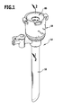
- Die nachfolgende Beschreibung bevorzugter Ausführungsformen der Erfindung dient im Zusammenhang mit der Zeichnung der näheren Erläuterung. Es zeigen:
- Figur 1:
- eine perspektivische Gesamtansicht eines chirurgischen Abdichtungssystems;
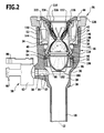
- Figur 2:
- eine Schnittansicht längs Linie 2-2 in
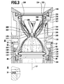
Figur 1 ; - Figur 3:
- eine vergrößerte Teilansicht der Schnittansicht in
Figur 2 ; - Figur 4:
- eine perspektivische Explosionsdarstellung des Abdichtungssystems aus
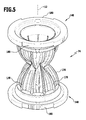
Figur 1 ; - Figur 5:
- eine perspektivische Ansicht des Dichtungselements aus
Figur 4 ; - Figur 6:
- eine Schnittansicht längs Linie 6-6 in
Figur 3 ; - Figur 7:
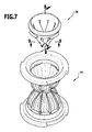
- eine perspektivische Explosionsdarstellung eines Dichtelements mit Schutzvorrichtung;
- Figur 8:
- eine Schnittansicht längs Linie 8-8 in
Figur 7 ; - Figur 9:
- eine Schnittansicht längs Linie 9-9 in
Figur 7 ; - Figur 10:
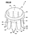
- eine perspektivische Ansicht der Schutzvorrichtung in einer maximal aufgeweiteten Stellung;
- Figur 11:
- eine Schnittansicht analog
Figur 3 beim Einführen eines Obturators des Abdichtungssystems; - Figur 12:
- eine Ansicht analog
Figur 1 des Abdichtungssystems mit eingesetztem Obturator; - Figur 13:
- eine Längsschnittansicht des in
Figur 12 dargestellten Obturators; und - Figur 14:
- eine Schnittansicht längs Linie 14-14 in
Figur 13 . - In den
Figuren 1 bis 13 ist ein insgesamt mit dem Bezugszeichen 10 versehenes, ein chirurgisches Abdichtungssystem bildendes Trokarsystem dargestellt. Es umfasst eine eine Längsachse 12 definierende Trokarhülse 14 mit einem Dichtungsgehäuse 16 und einem sich von diesem weg in distaler Richtung erstreckenden Schaft 18, eine im Dichtungsgehäuse 16 angeordnete Dichtungsanordnung 20 sowie einen Obturator 22, welcher ein speziell zum Trennen und Aufweiten von Körpergewebe geformtes distales Ende aufweist und vor dem Einführen der Trokarhülse 14 in einen Patientenkörper in die Trokarhülse 14 eingeschobenen wird, um das Einführen der Trokarhülse 14 in den Patientenkörper zu Erleichtern. - Die Trokarhülse 14 ist im Wesentlichen rotationssymmetrisch ausgebildet und definiert im Inneren des Dichtungsgehäuses 16 eine Aufnahme 24 für die Dichtungsanordnung 20. Ein minimaler Innendurchmesser der Trokarhülse 14 wird definiert durch den Schaft 18. In einem ersten Übergangsbereich 26 vom Schaft 18 zum Dichtungsgehäuse 16 erweitert sich der Innendurchmesser des Schafts 18 kontinuierlich und bleibt im Bereich eines ersten Erweiterungsraums 28 konstant. An den ersten Erweiterungsraum 28 schließt sich ein zweiter Übergangsbereich 30 an, in dem sich der Innendurchmesser der Trokarhülse 14 nochmals kontinuierlich erweitert bis zu einem distalen Teil 32 der Aufnahme 24.
- Ein Innendurchmesser des Dichtungsgehäuses 16 erweitert sich einstufig beim Übergang vom distalen Teil 32 zu einem proximalen Teil 34 desselben, so dass eine in proximaler Richtung weisende Ringfläche 36 definiert wird. Die Ringfläche kann optional eine zusätzliche Dichtung 37 tragen, welche durch Anspritzen eines Elastomers hergestellt und beispielhaft in
Figur 3 punktiert eingezeichnet ist. Eine flache Ausnehmung 38 in der Ringfläche definiert somit eine etwas in proximaler Richtung vorstehende ebene Dichtfläche 40, welche von einer Innenwand 42 des proximalen Teils 34 durch die Ausnehmung 38 getrennt ist. - Ausgehend von einem proximalen Ende 44 des Dichtungsgehäuses 16 sind diametral bezogen auf die Längsachse 12 einander gegenüberliegend zwei zueinander symmetrische Verriegelungsaufnahmen 46 ausgebildet, welche jeweils zwei seitliche Hinterschneidungen 48 aufweisen, welche in Umfangsrichtung in einander entgegengesetzte Richtungen geöffnet sind. Die Verriegelungsaufnahmen 46 bilden einen Teil einer Rastverbindung, mit welcher die Dichtungsanordnung 20 im Dichtungsgehäuse 16 verriegelt werden kann, wie nachfolgend noch im Einzelnen noch erläutert wird.
- Ferner ist ausgehend vom Ende 44 in einer Wand 52 des Dichtungsgehäuses 16 eine sich in distaler Richtung etwas verjüngende Aussparung 50 symmetrisch zwischen den Verriegelungsaufnahmen 46 ausgebildet, in welche ein entsprechender Vorsprung 250 des Obturators 22 eingreift, wenn der Obturator 22 vollständig in die Trokarhülse 14 eingeführt ist, wie dies in
Figur 12 dargestellt ist. - Am Dichtungsgehäuse 16 ist im Bereich des zweiten Übergangsbereichs 30 einseitig ein Anschlussstutzen 54 angeformt, welcher einen senkrecht zur Längsachse 12 verlaufenden Kanal 56 definiert. In den Kanal 56 eingesteckt ist ein Stutzen 57 eines Verschlusselements 58 mit einem in entgegengesetzter Richtung abstehenden, standardisierten Luer-Lock-Anschluss 60. Das Verschlusselement 58 umfasst ein zylindrisches Ventilgehäuse 62, in welchen ein korrespondierend ausgebildeter zylindrischer Verschlusskolben 64 mit einem angeformten Betätigungshebel 66 eingesetzt ist. Der Verschlusskolben 64 ist mit einer Bohrung 68 versehen, so dass in Abhängigkeit einer Verdrehstellung des Verschlusskolbens 64 relativ zum Ventilgehäuse 62 den Kanal 56 für Fluide geöffnet oder geschlossen werden kann. Statt des beschriebenen Verschlusselements 58 können auch beliebige andere Arten bekannter Verschlusselemente vorgesehen sein, insbesondere auch spezielle, federbelastete und dadurch selbstschließende Luer-Lock-Anschlüsse.
- Die Dichtungsanordnung 20 umfasst zwei Dichtungen, nämlich ein Kreuzschlitzventil 70, welches an einem Haltering 72 gehalten ist, sowie ein Dichtelement 74, welches in seinem prinzipiellen Aufbau im deutschen Gebrauchsmuster
20 2006 005 442 detailliert beschrieben ist. Die dortige Beschreibung wird hiermit in vollem Umfang in die vorliegende Beschreibung mit einbezogen. - Das Dichtelement 74 ist im Inneren einer Dichtelementhalterung 76 gehalten, welche mit dem Haltering 72 lösbar verbindbar ist. Proximalseitig ist am Dichtelement 74 eine Schutzvorrichtung 78 lösbar gehalten, so dass das Dichtelement 74 zusammen mit der Schutzvorrichtung 78 bei Bedarf aus der Dichtelementhalterung 76 entnommen werden kann. Proximalseitig kann die Dichtelementhalterung 76 noch mit einem Deckel 80 verschlossen werden.
- Die einzelnen Teile der Dichtungsanordnung 20 werden nachfolgend im Einzelnen näher beschrieben.
- Der Haltering 72 umfasst einen im Querschnitt kreisförmigen Ring 82, von dessen proximalseitigem Rand ein in proximaler Richtung abstehender ringförmiger Flansch 84 ausgebildet ist, welcher sich jedoch nicht über eine gesamte Breite einer Wand des Rings 82 erstreckt, sondern nur etwa über die Hälfte.
- Vom proximalen Rand des Rings 82 stehen ferner zwei zueinander symmetrisch ausgebildete Verbindungsflügel 86 einander, bezogen auf die Längsachse 12, diametral gegenüberliegend in proximaler Richtung ab. Die Verbindungsflügel 86 weisen jeweils zwei im Wesentlichen rechteckige Durchbrechungen 88 auf, welche quer zur Längsachse 12 orientiert sind. Die Verbindungsflügel 86 sind vom Flansch 84 etwas beabstandet angeordnet, so dass zwischen dem Flansch 84 und den Verbindungsflügeln 86 jeweils eine Nut 90 ausgebildet ist.
- Das Kreuzschlitzventil 70 umfasst proximalseitig einen ringförmigen Befestigungsflansch 92, welcher einen in distaler Richtung weisenden Ringvorsprung 94 trägt, welcher in seiner Höhe sowie in seinen äußeren Abmessungen korrespondierend zu den Nuten 90 ausgebildet ist. Das Kreuzschlitzventil 70 umfasst ferner einen am Befestigungsflansch 92 in distaler Richtung abstehenden Ventilkörper 96, welcher distalseitig in eine kreuzförmige Endfläche 98 mündet, die mit zwei zueinander senkrechten Schlitzen 100 versehen ist. Der Ventilkörper 96 ist in einer Grundstellung, wie sie beispielsweise in den
Figuren 2 und4 dargestellt ist, so ausgebildet, dass die durch die Schlitze 100 getrennten Schnittflächen 102 des Ventilkörpers 96 direkt aneinander anliegen und so eine durch den Befestigungsflansch 92 definierte ringförmige Öffnung 104 etwas distalseitig des Befestigungsflanschs 92 vollständig verschließen. Der Ventilkörper 96 ist proximalseitig direkt an einen Innenrand des Befestigungsflansch 92 angeformt, so dass zwischen dem Ventilkörper 96 und dem Ringvorsprung 94 eine Ringnut 106 ausgebildet wird, in welche der Flansch 84 im Wesentlichen formschlüssig eingreifen kann. - Der Befestigungsflansch 92 ist ferner mit zwei in radialer Richtung weisenden Aussparungen 108 versehen, in welche die Verbindungsflügel 86 eingreifen, wenn der Ventilkörper 96 in den Haltering 72 eingesetzt ist und mindestens teilweise mit dem Ventilkörper 96, insbesondere mit dessen die Schlitze 100 aufweisender Endfläche 98, über einen distalseitigen Rand des Rings 82 vorsteht.
- Die Dichtelementhalterung 76 ist im Wesentlichen langgestreckt hülsenförmig ausgebildet. Sie umfasst einen zentralen, koaxial zur Längsachse 22 ausgebildeten Hülsenkörper 110. Eine Innenfläche 112 des Hülsenkörpers 110 ist vollständig rotationssymmetrisch ausgebildet. Die Innenfläche 112 definiert und begrenzt einen Längskanal 114, in welchen das Dichtelement 74 eingesetzt ist. Ein Innendurchmesser des Hülsenkörpers 110 erweitert sich jeweils zum distalen und proximalen Ende desselben hin etwas. Distalseitig und proximalseitig sind jeweils ringförmige, in proximaler beziehungsweise distaler Richtung weisende Ringvorsprünge 116 und 118 ausgebildet, zum in Eingriff Bringen mit korrespondierenden Flanschen beziehungsweise Nuten am Dichtelement 74.
- Auf einer Außenseite des Hülsenkörpers 110 sind etwas proximalseitig des distalseitigen Ringvorsprungs 118 zwei bezogen auf die Längsachse 12 einander diametral gegenüberliegende und in entgegengesetzte Richtungen weisende Rastnasen 120 ausgebildet, welche nach außen weisende, etwas in distaler Richtung geneigte Aufgleitflächen 122 und somit auch eine in proximaler Richtung weisende Ringkante 124 definieren. Die Rastnasen 120 sind korrespondierend zu den Durchbrechungen 88 an den Verbindungsflügeln 86 ausgebildet. Die Verbindungsflügel 86 können von distal her kommend über die Aufgleitflächen 122 geschoben werden, so dass sie etwas in radialer Richtung von der Längsachse 12 weg nach außen ausschwenken. Sobald die Rastnasen 120 ganz in die Durchbrechungen 88 eingreifen können, federn die Verbindungsflügel 86 wieder in Richtung auf die Längsachse 12 zurück. Auf die beschriebene Weise können der Haltering 72 und die Dichtelementhalterung 76 rastend miteinander verbunden werden.
- Zwischen den Rastnasen 120, also um 90° relativ zu diesen in Umfangsrichtung versetzt, sind im Hülsenkörper 110 zwei rechteckige Durchbrechungen 123 vorgesehen, welche einen Innenraum 125 des Hülsenkörpers 110 mit einer Außenseite desselben verbinden. Auf diese Weise kann ein Druckausgleich zwischen dem Innenraum 125 und einer Umgebung der Dichtelementhalterung 76 erreicht werden. Der so erreichbare Druckausgleich zwischen einem im Körper eines Patienten herrschenden Gasdrucks und dem Innenraum 125 bzw. die so mögliche Ent-/Belüftung des Innenraums 125 verhindert, dass eine Aufweitung des Dichtelements 74 gegen ein Gasvolumen im Innenraum erfolgen muss, welches nach Montage des Dichtelements 74 an der Dichtelementhalterung 76 eingeschlossen würde.
- Zum Verbinden der Dichtelementhalterung 76 mit dem Dichtungsgehäuse 16 sind von einer Außenseite der Dichtelementhalterung 76 zwei Kupplungsglieder 126 einander diametral gegenüberliegend abstehend angeordnet. Sie umfassen jeweils einen direkt vom Hülsenkörper 110 in radialer Richtung abstehenden Quersteg 128, von welchem sich ein im Wesentlichen parallel zum Hülsenkörper 110 in proximaler Richtung erstreckender Federteil 130 weg erstreckt. An einem proximalen Ende des Federteils 130 sind beidseits des Federteils 130 im Wesentlichen in Umfangsrichtung weisende und überstehende Rastvorsprünge 132 ausgebildet, welche jeweils von der Längsachse 12 weg weisende Aufgleitflächen 134 definieren. Zwischen den Aufgleitflächen 134 ist auf einer Außenseite der Federteile 130 ein im Wesentlichen quaderförmiges Bedienelement 136 angeordnet, welches proximalseitig etwas über das Ende des Federteils 130 vorsteht.
- Zum Verbinden der Dichtelementhalterung 76 mit dem Dichtungsgehäuse 16 wird das distale Ende der Dichtelementhalterung 76 in das Dichtungsgehäuse 16 eingeführt, bis die die Hinterschneidungen 46 seitlich begrenzende Vorsprünge 49 mit den Aufgleitflächen 134 in Kontakt kommen und die Federteile 130 infolge des Aufgleitens etwas in Richtung auf die Längsachse 12 hin verschwenken. Sobald eine proximale Endfläche 138 der Federteile 130 in die Hinterschneidung 48 eintauchen kann, federn die Federteile 130 in radialer Richtung etwas nach außen und die Endfläche 130 liegt an einer in distaler Richtung weisenden Kante des Vorsprungs 49 an. Zum Lösen der Dichtelementhalterung 76 von der Trokarhülse 14 können die Bedienelemente 136 mit einer in Richtung auf die Längsachse 12 wirkenden Kraft beaufschlagt werden, so dass die Federteile 130 in Richtung auf die Längsachse 12 verschwenkt werden und die Rastvorsprünge 132 wieder die Hinterschneidung 48 freigeben. Die Dichtelementhalterung 76 kann dann in proximaler Richtung aus dem Dichtungsgehäuse 16 herausgezogen werden.
- Etwas distalseitig der Querstege 128 ist ein Halterungsdichtelement 140 ausgebildet, und zwar in Form eines im Wesentlichen in radialer Richtung abstehenden Ringflansches, welcher etwas in distaler Richtung geneigt ist, und zwar um etwa 2° bezogen auf eine senkrecht zur Längsachse 12 verlaufende Querebene. Das Halterungsdichtelement 140 weist eine Dicke auf, welche eine gewisse Elastizität beziehungsweise Flexibilität des Halterungsdichtelements 140 vorgibt. Es kann so in axialer Richtung etwas federn und Fertigungstoleranzen an der Trokarhülse 14 und der Dichtelementhalterung 76 ausgleichen. Das Halterungsdichtelement 140 ist an der Dichtelementhalterung 76 derart angeordnet, dass dann, wenn die Dichtelementhalterung 76 rastend in der beschriebenen Weise mit dem Dichtungsgehäuse 16 verbunden ist, eine in distaler Richtung weisende Dichtfläche 142 der Dichtelementhalterung 76 an der Ringfläche 36, optional etwas vorgespannt, anliegt und so eine perfekte Abdichtung der Dichtelementhalterung 76 bezogen auf eine Innenwand 144 des Dichtungsgehäuses 16 der Trokarhülse erreicht wird. Das Halterungsdichtelement 140 kann zur Verbesserung einer Abdichtungswirkung optional eine weitere Dichtung 141 tragen, welche durch Anspritzen eines Elastomers hergestellt und beispielhaft in
Figur 11 punktiert eingezeichnet ist. - Das Dichtelement 74 ist bezogen auf die Längsachse 12 im Wesentlichen rotationssymmetrisch ausgebildet. Ferner ist es bezogen auf eine quer zur Längsachse verlaufende Öffnungsebene 146 im Wesentlichen spiegelsymmetrisch ausgebildet. Die Öffnungsebene 146 verläuft parallel zu zwei beidseitigen Flanschringen 148, welche das Dichtelement 74 distal- und proximalseitig begrenzen und einen maximalen Außendurchmesser des Dichtelements 74 definieren. Von den Flanschringen 148 stehen maximal weit außen an ihnen und jeweils in die Richtung des anderen Flanschrings 148 hin weisend Ringvorsprünge 150 ab, welche die Ringvorsprünge 116 und 118 außen umgreifen können. Das Dichtelement 74 kann so auf einfache Weise über die Ringvorsprünge 116 und 118 gehängt oder gespannt und im Inneren der Dichtelementhalterung 76 gehalten werden.
- Von den Flanschringen 148 erstreckt sich in radialer Richtung auf die Längsachse 12 hin ein erster Querabschnitt 152, welche in einen ersten, nach außen zurückgebogenen ersten Wulstabschnitt 154 übergeht, welcher wiederum direkt in einen zweiten Wulstabschnitt 156 übergeht, welcher wiederum ein auf die Längsachse 12 hin gerichtetes Ende aufweist. Der zweite Wulstabschnitt 156 definiert so eine in Richtung auf die Längsachse hin geöffnete Ringnut 158.
- Distalseitig schließt sich an den zweiten Wulstabschnitt 156 ein kurzer zylindrischer Abschnitt 160 an, welcher in einen verdickten, außen am Dichtelement 74 abstehenden Wulst 162 übergeht. Ausgehend von den Wulsten 162, an denen eine Wand 164 des Dichtelements 74 im Wesentlichen faltenfrei absteht, faltet sich die Wand 164 gardinenartig bis zur Öffnungsebene 146 hin. Durch die Faltung entsteht eine Dichtlinie 166, welche in Form einer Wellenlinie Wellenberge 170 proximalseitig der Öffnungsebene 146 und Wellentäler 172 distalseitig der Öffnungsebene 146 definiert. Die Wellenlinie 168 ist etwas verstärkt und in Form einer Dichtlippe 174 ausgebildet, welche sich somit teilweise proximalseitig und teilweise distalseitig der Öffnungsebene 146 befindet. In einer Draufsicht, wie in
Figur 6 dargestellt, ist jedoch erkennbar, dass die Dichtlinie 166 und damit auch die Dichtlippe 174 eine kreisringförmige Öffnung 176 des Dichtelements 74 begrenzen. Die Öffnung 176 weist in einer Grundstellung, wie sie beispielsweise in denFiguren 3 bis 6 dargestellt ist, einen minimalen Innendurchmesser auf. Die Öffnung 176 kann, wie beispielsweise inFigur 11 dargestellt, so weit aufgeweitet werden, dass ein Innendurchmesser derselben einem Innendurchmesser des Dichtelements 74 im Bereich der Wulste 162 entspricht. Die gefaltete Wand 164 entfaltet sich dabei, ist praktisch auf der gesamten Länge zwischen den Wulsten 162 vollständig umfaltet und definiert so eine im Wesentlichen zylindrische Wandfläche. - Zur Stabilisierung des Dichtelements 74 sind auf einer Außenseite der Wand 164 ausgehend von den Wulsten 164 bis an die Dichtlippe 166 heranreichende Verstärkungsrippen 178 ausgebildet. Das Dichtelement 74 ist insgesamt einstückig aus einem Kunststoff gespritzt, welcher vorzugsweise elastomerische Eigenschaften aufweist. Ferner sind an den Flanschringen 148 jeweils zwei, einander diametral gegenüberliegende Aussparungen 180 vorgesehen, welche korrespondierend zu zwei in radialer Richtung von der Dichtelementhalterung 76 in Richtung auf die Längsachse 12 hin vorstehenden Vorsprüngen 182 ausgebildet sind. Die Aussparungen 180 in Verbindung mit den Vorsprüngen 182 bilden eine Verdrehsicherung, so dass das Dichtelement 74 und die Dichtelementhalterung 76 in einer beispielsweise in den
Figuren 2 und3 dargestellten Montagestellung nicht um die Längsachse 12 relativ zueinander verdrehbar sind. - Nach Bestücken des Halterings 72 mit dem Kreuzschlitzventil 70 kann die Dichtelementhalterung 76, in welche das Dichtelement 74 in der oben beschriebenen Weise eingesetzt ist, mit dem Haltering 72 verbunden werden. Distalseitig bildet eine in distaler Richtung weisende ringförmige Stirnfläche 184 des Dichtelements 74 ein Anlagefläche für den Befestigungsflansch 92. Durch rastendes Verbinden des Halterings 72 mit der Dichtelementhalterung 76 in der oben beschriebenen Weise, werden der Befestigungsflansch 92 und der Flanschring 148 gegeneinander gedrückt und bilden eine perfekte Abdichtung.
- Zumindest im proximalseitigen Wulst 162 sind vier gleichmäßig über den Umfang verteilte, in radialer Richtung auf die Längsachse 12 hin geöffnete und Verbindungsglieder bildende Vertiefungen 186 vorgesehen, welche der Aufnahme korrespondierender Verbindungselemente 188 der Schutzvorrichtung 78 dienen. Die Schutzvorrichtung 78 umfasst einen ringförmigen, in sich geschlossenen Grundkörper 190, welcher eine kreisförmige Durchbrechung 192 definiert. Vom Grundkörper 190 steht ein in radialer Richtung nach außen weisend benachbart einem proximalen Ende 194 ein Ringvorsprung 196 ab. Etwas weiter distalseitig sind die Verbindungselemente 188 in Form kurzer stegartiger Vorsprünge angeordnet. Sie erstrecken sich im Umfang über etwa 1/8 des Gesamtumfangs des Grundkörpers 190 und sind korrespondierend zu den Vertiefungen 186 ausgebildet. Der Grundkörper 190 kann somit direkt am Dichtelement 74 gelagert werden, wobei hierfür die Verbindungselemente 188 formschlüssig in die Vertiefungen 168 eingreifen. Sie bilden somit gleichzeitig eine Verdrehsicherung der Schutzvorrichtung 78 relativ zum Dichtelement 74. Ferner bilden sie auch eine Positionierhilfe der Schutzvorrichtung 78 relativ zum Dichtelement 74.
- Von einem distalseitigen Rand 198 des Grundkörpers 190 erstrecken sich insgesamt 10, jeweils fünf lamellenförmige kurze Schutzelemente 200 und fünf lange Schutzelemente 202 in distaler Richtung. Sie weisen im Längsschnitt, wie in
Figur 8 dargestellt, eine über ihre gesamte Länge konstante Dicke auf. Die kurzen Schutzelemente 200 sind im Wesentlichen bis zu ihrem freien Ende 204 nahezu gleich breit, die langen Schutzelemente 202 in etwa auf derselben Länge wie die kurzen Schutzelemente 200, allerdings nimmt dann eine Breite der langen Schutzelemente 202 auf deren distales Ende 206 hin deutlich ab, so dass ein schmaler Schutzelementabschnitt 208 ausgebildet wird, welcher in seiner Außenkontur im Wesentlichen korrespondierend zu einem Wellental 172 ausgebildet ist. - Die langen Schutzelemente 202 tragen jeweils ein von einer Außenseite 210 etwas in distaler Richtung geneigt abstehendes Rückhalteelement 212, welches eine Länge von weniger als 1mm aufweist. Das Rückhalteelement ist im Wesentlichen kegelstumpfförmig ausgebildet und weist eine abgerundete Spitze 214 auf.
- Wenn der Grundkörper 190 in der oben beschriebenen Weise mit dem Dichtelement 174 verbunden ist, falten sich die aufgrund ihrer geringen Dicke flexiblen Schutzelemente 200 und 202 in Richtung auf die Längsachse 12 hin und nehmen die in den
Figuren 6 bis 8 dargestellte Stellung ein. Es sei angemerkt, dass sich die langen Schutzelemente 202 distalseitig der Verbindungselemente 188 vom Rand 198 weg erstrecken, die kurzen Schutzelemente 200 in den Bereichen des Rands 198, zu welchem kein Verbindungselement 188 korrespondiert. Durch die entsprechend vorgesehenen Vertiefungen 186 kann die Schutzvorrichtung 78 positionsrichtig mit dem Dichtelement 74 verbunden werden, dies bedeutet, dass in einer Grundstellung alle fünf Schutzelementabschnitte 208 in korrespondierende Wellentäler 172 eintauchen. Damit ist sichergestellt, dass die distalen Enden 204 und 206 der Schutzvorrichtung 78 praktisch bis an die Dichtlinie 166 heranreichen und im Wesentlichen eine innere Wandfläche 216 des Dichtelements 74 vollständig verdecken. - Die Schutzelemente 200 und 202 stehen in der montierten Grundstellung bereits wenig distalseitig des Wulsts 162 von der Wandfläche 216 ab und berühren diese allenfalls nahe ihrer Enden 204 und 206. In der Grundstellung sind die Schutzelemente 200 und 202 einander überlappend angeordnet, wobei die kurzen Schutzelemente 200 näher an der Längsachse 12 liegen als die langen Schutzelemente 202. Dadurch berühren lediglich die Rückhalteelemente 212 benachbart der Dichtlinie 166 die Wand 164 des Dichtelements 74.
- Wird ein Instrument, oder wie beispielsweise in
Figur 11 dargestellt, der Obturator 22, von proximal her kommend in das Dichtelement 74 eingeführt, so tritt es zunächst in Kontakt mit Innenflächen der kurzen Schutzelemente 200. Ist ein Außendurchmesser, wie dies beim Obturator 22 der Fall ist, eines Instruments größer als die Öffnung 176, dann werden die kurzen Schutzelemente 200 gegen die langen Schutzelemente 202 gedrückt und nach außen verschwenkt. Dabei werden auch die Rückhalteelemente 212 mit ihren Spitzen 214 in die Wand 164 des Dichtelements 74 eingedrückt. Dies führt zu einer Auswölbung 218 der Wand 164 durch die Rückhalteelemente 212, so dass sich diese in der Wand 164 verhaken, man kann auch sagen, die Rückhalteelemente 212 und das Dichtelement 74 stehen miteinander in Eingriff. Durch das Verhaken der Rückhalteelemente 212 in der Wand 164 wird eine Relativbewegung der distalen Enden 206 der langen Schutzelemente 202 relativ zum Dichtelement 74 praktisch verhindert. Unabhängig von einer Aufweitung oder Auffaltung der Wand 164 in Abhängigkeit eines Durchmessers des eingeführten Instruments reichen die distalen Enden 206 der langen Schutzelemente 202 stets bis an die Dichtlinie 166 heran und schützen das Dichtelement 74 vor den eingangs beschriebenen möglichen Beschädigungen infolge des in Kontakt Tretens der Wand 164 mit spitzen Kanten der eingeführten Instrumente. - Selbst dann, wenn eine Längsachse des eingeführten Instruments relativ zur Längsachse 12 etwas verkippt wird, bleibt der Verhakeeffekt der Rückhalteelemente 212 erhalten. Durch eine von den Vertiefungen 186 und den Verbindungselementen 188 ausgebildete Verbindungseinrichtung 220 wird eine Verkippung des zunächst an der Schutzvorrichtung anliegenden Instrumentenschafts direkt auf das Dichtelement 74 übertragen, und zwar im Bereich des Wulstes 162, so dass das Dichtelement 74 analog zu einer Verkippung der Schutzvorrichtung 78 mit verkippt wird. Die besondere Anordnung der Schutzvorrichtung 78 am Dichtelement 74 bildet somit quasi auch eine Neigungsanpassung bei der Einführung von Instrumenten. Hierfür dienlich ist zudem insbesondere der erste Wulstabschnitt 154, welcher sowohl eine Verkippbewegung als auch eine transversale Bewegung, zumindest soweit der erste Wulstabschnitt 154 von einer Innenwand der Dichtelementhalterung 76 beabstandet ist, gestattet.
- Durch die Wölbung der Schutzelemente 200 und 202 schwach konvex von der Wand 164 weg, ist sichergestellt, dass ein eingeführtes Instrument zunächst mit distalen Endbereichen der Schutzelemente 200 und 202 in Kontakt tritt, bevor es die Dichtlippe 174 berühren kann.
- Zum Verschließen des Dichtungsgehäuses 16 dient der Deckel 80. Er umfasst einen ringförmigen Rahmen 222, von dem sich im Innern und in distaler Richtung eine sich im Durchmesser konisch verjüngende Deckelfläche 224 bis zu einer Deckelöffnung 226 erstreckt, welche einen maximalen Innendurchmesser der Dichtungsanordnung 20 definiert. Instrumente mit Schaftdurchmessern, welche größer sind als ein Innendurchmesser der Deckeöffnung 226, können nicht in die Trokarhülse 14 eingeführt werden. Der Deckel 80 weist ferner zwei in distaler Richtung weisende, einander gegenüberliegende Laschen 228 auf, welche an freien Enden Rastvorsprünge 230 aufweisen, welche mit korrespondierenden, in den Figuren nicht dargestellten Rastkanten an der Dichtelementhalterung 76 in Eingriff gebracht werden können. Der Deckel 80 kann dann nach Montage der Dichtelementhalterung 76 am Dichtungsgehäuse 16 auf einfache Weise auf die Dichtelementhalterung 76 aufgeschnappt werden.
- Um die Trokarhülse 14 in einen menschlichen oder tierischen Körper einführen zu können, ist der Obturator 22 vorgesehen. Er umfasst einen hohlen, koaxial zur Längsachse 12 verlaufenden Schaft 232, welcher sich in einem distalen Endbereich 234 im Außendurchmesser kontinuierlich verjüngt und eine abgerundete Spitze 236 definiert. Der Endbereich 234 ist im Querschnitt an keiner Stelle kreisförmig, sondern in Folge definierter, sich parallel zur Längsachse 12 erstreckender Vertiefungen 238 unsymmetrisch ausgebildet. In einem proximalen Endbereich 240 sind an einer Außenseite des Schafts 232 vier jeweils 90° zueinander versetzt angeordnete Haltevorsprünge 242 vorgesehen, welche der Lagerung und Verbindung eines im Wesentlichen die Form einer Halbkugel aufweisenden Deckels 244 dienen. Am Deckel 244 sind auf einer Innenseite korrespondiere Vorsprünge 246 ausgebildet. Optional kann der Deckel 244 auch mit dem Schaft 232 und dessen Haltevorsprüngen 242 verschraubt oder verklebt sein. Des Weiteren steht vom Deckel 244 in distaler Richtung weisend der lappenförmige Vorsprung 250 ab, welcher korrespondierend zur Aussparung 50 ausgebildet ist, so dass der Obturator 22 mit einer definierten Orientierung bezogen auf die Längsachse 12 in die Trokarhülse 14 eingesetzt werden kann. Ist der Obturator 22 vollständig in die Trokarhülse 14 eingeschoben, steht der distale Endbereich 234 über eine bezogen auf die Längsachse 12 um etwa 45° geneigte Endfläche 252 des Schafts 18 vor, wie dies in
Figur 12 dargestellt ist. - Im Inneren des Dichtungsgehäuses 16 erfolgt eine Abdichtung über das Dichtelement 74 sowie zu einem Außenbereich der Dichtelementhalterung 76 und der Innenwand 144 der Trokarhülse 14 mittels des Halterungsdichtelements 140. Wird der Obturator 22 aus der Trokarhülse 14 entfernt, verschließt das Kreuzschlitzventil 70 einen sich längs der Trokarhülse 14 erstreckenden Kanal fluiddicht. Aufgrund der etwas von der Längsachse 12 weg weisenden Außenflächen des Ventilkörpers 96 werden diese, falls im Körperinneren und somit im Bereich des Schafts 18 ein Überdruck besteht, die Schnittflächen 102 zusätzlich gegeneinander gedrückt, um die Schlitze 100 zu verschließen. Damit kann bei laparoskopischen Eingriffen, bei denen im Bauchraum eines Patienten mittels eines Gases ein Überdruck erzeugt wird, um einen Operationssitus freizuhalten, dieser Überdruck gehalten werden, auch dann, wenn Instrumente, oder zum Beispiel in analoger Weise der Obturator 22, mittels des Trokarsystems 10 ins Körperinnere eingeführt werden.
- Zu beachten ist ferner, dass das Kreuzschlitzventil 70 erst mittels eines distalen Endes eines Instruments oder beispielsweise der Spitze 236 des Obturators 22 geöffnet werden kann, wenn beim Einführen eines Instruments dessen Schaft, beispielsweise der Schafts 232 des Obturators 22, mittels der Dichtlippe 144 des Dichtelements 74 abgedichtet ist. So ist sichergestellt, dass entweder das Kreuzschlitzventil 70 geschlossen oder eine Abdichtung mittels des Dichtelements 74 relativ zum eingeführten Instrument erfolgt.
- Die Trokarhülse 14, der Haltering 72, das Kreuzschlitzventil 70, das Dichtungselement 74, die Schutzvorrichtung 78, die Dichtelementhalterung 76 sowie der Deckel 80 sind jeweils einstückig ausgebildet und vorzugsweise aus einem sterilisierbaren Kunststoffmaterial gespritzt. Der Obturator 22 ist wie beschrieben zweiteilig ausgebildet und kann ebenfalls an einem Kunststoffmaterial durch Spritzgießen hergestellt sein.
- Über das Verschlusselement 58 kann bei entsprechender Stellung des Verschlusskolbens 64 ein Gas oder eine Flüssigkeit durch den Schaft 18 ins Innere eines Patientenkörpers eingeleitet oder auch abgeführt werden, selbst dann, wenn ein Instrument, beispielsweise der Obturator 22 in die Trokarhülse 14 eingeführt und ein durch die Trokarhülse 14 definierter Kanal proximalseitig des Anschlussstutzens 54 abgedichtet ist.
Claims (15)
- Chirurgische Dichtelementhalterung (76) zum Halten eines chirurgischen, eine erweiterbare Einführöffnung (176) aufweisenden Dichtelements (74) eines chirurgischen, einen Trokar (14, 22) mit einer Trokarhülse (14) umfassenden Abdichtungssystems (10), gekennzeichnet durch ein Halterungsdichtelement (140) zum Abdichten der Dichtelementhalterung (76) mit Bezug zu einer inneren Wandfläche (144) der Trokarhülse (14).
- Chirurgische Dichtelementhalterung nach Anspruch 1, dadurch gekennzeichnet, dass die Dichtelementhalterung (76) ausgebildet ist zum lösbaren Verbinden mit der Trokarhülse (14).
- Chirurgische Dichtelementhalterung nach Anspruch 1 oder 2, dadurch gekennzeichnet, dass das Halterungsdichtelement (140) in Form eines in radialer Richtung von der Dichtelementhalterung (76) abstehenden Flansches (140) ausgebildet ist.
- Chirurgische Dichtelementhalterung nach einem der voranstehenden Ansprüche, dadurch gekennzeichnet, dass das Halterungsdichtelement (140) einstückig mit der Dichtelementhalterung (76) ausgebildet ist.
- Chirurgische Dichtelementhalterung nach einem der voranstehenden Ansprüche, dadurch gekennzeichnet, dass das Halterungsdichtelement (140) mindestens abschnittsweise elastisch verformbar ist.
- Chirurgische Dichtelementhalterung nach einem der voranstehenden Ansprüche, dadurch gekennzeichnet, dass das Halterungsdichtelement (140) eine weitere Dichtung trägt.
- Chirurgische Dichtelementhalterung nach Anspruch 6, dadurch gekennzeichnet, dass die weitere Dichtung an das Halterungsdichtelement (140) angeformt ist.
- Chirurgische Dichtelementhalterung nach Anspruch 7 oder 8, dadurch gekennzeichnet, dass die weitere Dichtung aus einem Elastomer hergestellt ist.
- Chirurgisches Abdichtungssystem (10) umfassend einen Trokar (14, 22) mit einer Trokarhülse (14) und eine chirurgische Dichtelementhalterung (76) zum Halten eines chirurgischen, eine erweiterbare Einführöffnung (176) aufweisenden Dichtelements (74), dadurch gekennzeichnet, dass die Dichtelementhalterung (76) ein Halterungsdichtelement (140) zum Abdichten der Dichtelementhalterung (76) mit Bezug zu einer inneren Wandfläche (144) der Trokarhülse (14) aufweist.
- Chirurgisches Abdichtungssystem nach Anspruch 9, gekennzeichnet durch eine Dichtelementhalterung (76) nach einem der Ansprüche 2 bis 9.
- Chirurgisches Abdichtungssystem nach Anspruch 9 oder 10, dadurch gekennzeichnet, dass das Halterungsdichtelement (140) an einer in proximaler oder im Wesentlichen in proximaler Richtung weisenden Ringfläche (36) der Trokarhülse (14) anliegt.
- Chirurgisches Abdichtungssystem nach Anspruch 11, dadurch gekennzeichnet, dass die Ringfläche (36) eine in zusätzliche Dichtung trägt.
- Chirurgisches Abdichtungssystem nach Anspruch 12, dadurch gekennzeichnet, dass die zusätzliche Dichtung an die Ringfläche (36) angeformt ist.
- Chirurgisches Abdichtungssystem nach Anspruch 12 oder 13, dadurch gekennzeichnet, dass die zusätzliche Dichtung aus einem Elastomer hergestellt ist.
- Chirurgisches Abdichtungssystem nach einem der Ansprüche 11 bis 14, dadurch gekennzeichnet, dass die Ringfläche (36) durch eine einstufige Durchmesserverjüngung eines Innendurchmesser der Trokarhülse (14) definiert ist.
Applications Claiming Priority (1)
| Application Number | Priority Date | Filing Date | Title |
|---|---|---|---|
| DE102008033375A DE102008033375A1 (de) | 2008-07-09 | 2008-07-09 | Chirurgische Dichtelementhalterung zum Halten eines chirurgischen Dichtelements und chirurgisches Abdichtungssystem |
Publications (3)
| Publication Number | Publication Date |
|---|---|
| EP2143392A2 true EP2143392A2 (de) | 2010-01-13 |
| EP2143392A3 EP2143392A3 (de) | 2010-11-03 |
| EP2143392B1 EP2143392B1 (de) | 2015-12-16 |
Family
ID=41256056
Family Applications (1)
| Application Number | Title | Priority Date | Filing Date |
|---|---|---|---|
| EP09163064.0A Active EP2143392B1 (de) | 2008-07-09 | 2009-06-18 | Chirurgische Dichtelementhalterung zum Halten eines chirurgischen Dichtelements und chirurgisches Abdichtungssystem |
Country Status (4)
| Country | Link |
|---|---|
| US (2) | US8246586B2 (de) |
| EP (1) | EP2143392B1 (de) |
| DE (1) | DE102008033375A1 (de) |
| ES (1) | ES2561361T3 (de) |
Cited By (2)
| Publication number | Priority date | Publication date | Assignee | Title |
|---|---|---|---|---|
| WO2016144180A1 (en) * | 2015-03-12 | 2016-09-15 | Mofixx B.V. | Guiding trocar and system for connecting to a guiding trocar |
| CN108652712A (zh) * | 2017-04-01 | 2018-10-16 | 江苏风和医疗器材股份有限公司 | 穿刺器、密封组件及用于穿刺器的密封膜 |
Families Citing this family (12)
| Publication number | Priority date | Publication date | Assignee | Title |
|---|---|---|---|---|
| JP5497186B2 (ja) * | 2009-10-07 | 2014-05-21 | イューエムセー ユトレヒト ホールディング ベースローテン フェンノートシャップ | 手動操作医療装置を保持するための保持装置 |
| CN102551845B (zh) * | 2010-12-21 | 2016-03-02 | 周星 | 用于穿刺器的环型密封装置及穿刺器 |
| US9795409B2 (en) | 2012-11-20 | 2017-10-24 | Trokasure Gbr | Trocar device and use thereof |
| JP6483619B2 (ja) * | 2012-12-19 | 2019-03-13 | サージクェスト,インコーポレーテッド | トロカールに管セットを接続するための結合器 |
| US9545264B2 (en) * | 2014-06-06 | 2017-01-17 | Surgiquest, Inc. | Trocars and obturators |
| ES2699383T3 (es) | 2014-07-08 | 2019-02-11 | Applied Med Resources | Cierre de instrumento altamente sensible |
| US20160192828A1 (en) * | 2015-01-07 | 2016-07-07 | Nicholes Sexton | Retractor cannula and method of use |
| US10980952B2 (en) * | 2016-05-13 | 2021-04-20 | Intuitive Surgical Operations, Inc. | Universal cannula seal |
| US10568706B2 (en) * | 2016-12-15 | 2020-02-25 | Ethicon Llc | Trocar Simulation |
| CN113827312B (zh) * | 2021-09-18 | 2023-06-13 | 晨兴(南通)医疗器械有限公司 | 肺动脉取栓器用输送系统 |
| CN115399841B (zh) * | 2022-07-28 | 2025-07-18 | 澳灵特视医疗器械(杭州)有限公司 | 一种气压自锁穿刺器 |
| CN121774604A (zh) * | 2023-12-07 | 2026-04-03 | 广州迪克医疗器械有限公司 | 用于穿刺器的密封圈保护片、端密封组件及穿刺器 |
Citations (1)
| Publication number | Priority date | Publication date | Assignee | Title |
|---|---|---|---|---|
| DE202006005442U1 (de) | 2006-03-27 | 2006-06-14 | Aesculap Ag & Co. Kg | Chirurgisches Dichtelement, chirurgische Dichtung und chirurgisches Abdichtungssystem |
Family Cites Families (111)
| Publication number | Priority date | Publication date | Assignee | Title |
|---|---|---|---|---|
| US3712298A (en) * | 1970-08-25 | 1973-01-23 | Nat Res Dev | Medical treatment apparatus |
| SE363734B (de) | 1972-06-09 | 1974-02-04 | Moelnlycke Ab | |
| GB1466242A (en) | 1973-06-29 | 1977-03-02 | Matburn Ltd | Catheter valve |
| US4265694A (en) * | 1978-12-14 | 1981-05-05 | The United States Of America As Represented By The Department Of Health, Education And Welfare | Method of making unitized three leaflet heart valve |
| US5308336A (en) * | 1982-09-28 | 1994-05-03 | Applied Medical Resources | Seal protection mechanism |
| US4929235A (en) * | 1985-07-31 | 1990-05-29 | Universal Medical Instrument Corp. | Self-sealing percutaneous tube introducer |
| EP0312219B1 (de) | 1987-10-13 | 1994-12-14 | United States Surgical Corporation | Trokarbesteck |
| US5215526A (en) * | 1988-07-06 | 1993-06-01 | Ethicon, Inc. | Safety trocar |
| GB8816033D0 (en) | 1988-07-06 | 1988-08-10 | Ethicon Inc | Improved safety trocar |
| US5267965A (en) * | 1988-07-06 | 1993-12-07 | Ethicon, Inc. | Safety trocar |
| US4924923A (en) * | 1989-05-17 | 1990-05-15 | Vernay Laboratories, Inc. | Fuel filler pipe seal |
| US5127626A (en) * | 1989-10-31 | 1992-07-07 | Applied Vascular Devices, Inc. | Apparatus for sealing around members extending therethrough |
| FR2657941B1 (fr) | 1990-02-07 | 1992-04-17 | Caoutchouc Manuf Plastique | Armature de renfort articulee pour talon de renforcement de structure tubulaire souple et structure tubulaire souple comportant une telle armature de renfort. |
| US5114407A (en) * | 1990-08-30 | 1992-05-19 | Ethicon, Inc. | Safety mechanism for trocar |
| AU644900B2 (en) * | 1990-10-05 | 1993-12-23 | United States Surgical Corporation | Safety trocar |
| GR1000973B (el) | 1990-12-14 | 1993-03-16 | Ethicon Inc | Εν?ετο για τροκάρ με προφυλακτήρα. |
| US5261891A (en) * | 1991-01-15 | 1993-11-16 | Ethicon, Inc. | Trocar |
| US5104382A (en) | 1991-01-15 | 1992-04-14 | Ethicon, Inc. | Trocar |
| AU648135B2 (en) * | 1991-01-15 | 1994-04-14 | Ethicon Inc. | Knife for surgical trocar |
| US5474539A (en) * | 1991-02-07 | 1995-12-12 | Origin Medsystems, Inc. | Trocar with retracting tip |
| US5152754A (en) | 1991-02-15 | 1992-10-06 | Minnesota Mining And Manufacturing Company | Trocar |
| US5295993A (en) | 1991-04-30 | 1994-03-22 | United States Surgical Corporation | Safety trocar |
| US5180373A (en) | 1991-06-07 | 1993-01-19 | United States Surgical Corporation | Valve system for introducing objects into anatomical body portions |
| CA2069060C (en) | 1991-06-26 | 2003-07-29 | Daniel Shichman | Powered trocar |
| US5269763A (en) * | 1991-07-18 | 1993-12-14 | Vernay Laboratories, Inc. | Self-sealing cannula cap |
| US5385553A (en) | 1991-07-18 | 1995-01-31 | Applied Medical Resources Corporation | Trocar with floating septum seal |
| DE600921T1 (de) | 1991-08-30 | 1995-04-20 | Origin Medsystems Inc | Trokar mit zurückziehbarer spitze. |
| US5141498A (en) * | 1991-09-10 | 1992-08-25 | Unisurge, Incorporated | Flexible valve and device incorporating the same |
| US5203773A (en) * | 1991-10-18 | 1993-04-20 | United States Surgical Corporation | Tissue gripping apparatus for use with a cannula or trocar assembly |
| US5197955A (en) * | 1991-10-18 | 1993-03-30 | Ethicon, Inc. | Universal seal for trocar assembly |
| US5441513A (en) | 1992-03-12 | 1995-08-15 | United States Surgical Corporation | Retracting tip trocar assembly |
| DE4303026C2 (de) | 1992-04-02 | 1995-05-24 | Kuehlmann Manfred | Trokar für minimal invasive Chirurgie |
| CA2093754C (en) | 1992-04-24 | 1996-08-13 | David T. Green | Valve assembly for introducing instruments into body cavities |
| US5405328A (en) * | 1992-06-17 | 1995-04-11 | Minnesota Mining And Manufacturing Company | Trocar with replaceable obturator |
| US5256147A (en) * | 1992-06-17 | 1993-10-26 | Minnesota Mining And Manufacturing Company | Reusable trocar with easily replaceable obturator |
| US5443452A (en) | 1992-07-02 | 1995-08-22 | Applied Medical Resources | Seal assembly for access device |
| US5356421A (en) | 1992-10-07 | 1994-10-18 | United States Surgical Corporation | Safety trocar with locking handles |
| US5476475A (en) * | 1992-11-23 | 1995-12-19 | Applied Medical Resources | Trocar with universal seal protector |
| US5314417A (en) | 1992-12-22 | 1994-05-24 | Ethicon, Inc. | Safety trocar |
| US5387197A (en) * | 1993-02-25 | 1995-02-07 | Ethicon, Inc. | Trocar safety shield locking mechanism |
| US5462532A (en) * | 1993-03-17 | 1995-10-31 | Origin Medsystems, Inc. | Trocar with safety sensing sleeve |
| US5342315A (en) * | 1993-04-12 | 1994-08-30 | Ethicon, Inc. | Trocar seal/protector assemblies |
| US5346459A (en) | 1993-04-14 | 1994-09-13 | Minnesota Mining And Manufacturing Company | Trocar |
| US5657963A (en) | 1993-06-16 | 1997-08-19 | United States Surgical Corporation | Seal assembly for accommodating introduction of surgical instruments |
| US5441041A (en) * | 1993-09-13 | 1995-08-15 | United States Surgical Corporation | Optical trocar |
| US5690664A (en) * | 1993-09-13 | 1997-11-25 | United States Surgical Corporation | Trocar having movable blade |
| US5467762A (en) | 1993-09-13 | 1995-11-21 | United States Surgical Corporation | Optical trocar |
| CA2134174A1 (en) | 1993-10-26 | 1995-04-27 | Joseph Young | Trocar with a retractable cannula |
| US5330437A (en) | 1993-11-12 | 1994-07-19 | Ethicon Endo-Surgery | Self sealing flexible elastomeric valve and trocar assembly for incorporating same |
| WO1995022289A2 (en) | 1994-02-18 | 1995-08-24 | Gaya Limited | Surgical apparatus |
| CA2149290C (en) * | 1994-05-26 | 2006-07-18 | Carl T. Urban | Optical trocar |
| US5603702A (en) * | 1994-08-08 | 1997-02-18 | United States Surgical Corporation | Valve system for cannula assembly |
| AU699844B2 (en) | 1994-08-25 | 1998-12-17 | Ethicon Endo-Surgery, Inc. | Safety trocar |
| US5522833A (en) * | 1994-08-29 | 1996-06-04 | Ethicon Endo-Surgery, Inc. | Retractable obturator for a trocar |
| US5752938A (en) | 1994-09-12 | 1998-05-19 | Richard-Allan Medical Industries, Inc. | Seal for surgical instruments |
| US5618297A (en) | 1994-10-13 | 1997-04-08 | Applied Medical Resources | Obturator with internal tip protector |
| US5569292A (en) * | 1995-02-01 | 1996-10-29 | Ethicon Endo-Surgery, Inc. | Surgical penetration instrument with transparent blades and tip cover |
| US5584850A (en) | 1995-05-25 | 1996-12-17 | Applied Medical Resources Corporation | Trocar having an anti-inversion seal |
| US5662615A (en) * | 1995-09-01 | 1997-09-02 | Blake, Iii; Joseph W. | Valve and valve cartridge for trocar |
| US5609604A (en) | 1995-10-16 | 1997-03-11 | Ethicon Endo-Surgery, Inc. | Trocar with improved blade attachment |
| US5709671A (en) | 1995-10-16 | 1998-01-20 | Ethicon Endo-Surgery, Inc. | Trocar having an improved tip configuration |
| US5807338A (en) | 1995-10-20 | 1998-09-15 | United States Surgical Corporation | Modular trocar system and methods of assembly |
| US5669885A (en) | 1996-05-14 | 1997-09-23 | United States Surgical Corporation | Trocar assembly with spring-loaded mechanism |
| US5792113A (en) * | 1996-12-12 | 1998-08-11 | Ethicon Endo-Surgerym Inc. | Universal seal for a trocar |
| US5879332A (en) | 1997-03-26 | 1999-03-09 | Ethicon Endo-Surgery, Inc. | Trocar having protector with flexible end |
| US5906595A (en) * | 1997-04-25 | 1999-05-25 | Ethicon Endo-Surgery, Inc. | Trocar having protector with flexible end and improved seal assembly |
| DE69841230D1 (de) | 1997-05-02 | 2009-11-19 | United States Surgical Corp | Kanülenanordnung |
| US5817061A (en) * | 1997-05-16 | 1998-10-06 | Ethicon Endo-Surgery, Inc. | Trocar assembly |
| US6004326A (en) | 1997-09-10 | 1999-12-21 | United States Surgical | Method and instrumentation for implant insertion |
| US5904699A (en) * | 1997-09-19 | 1999-05-18 | Ethicon Endo-Surgery, Inc. | Trocar for penetration and skin incision |
| US5916232A (en) * | 1997-10-10 | 1999-06-29 | Applied Medical Resources Corporation | Asymmetrical obturator |
| US5989224A (en) * | 1998-02-23 | 1999-11-23 | Dexide Corporation | Universal seal for use with endoscopic cannula |
| US6113078A (en) | 1998-03-18 | 2000-09-05 | Lytesyde, Llc | Fluid processing method |
| CA2294054C (en) | 1998-04-13 | 2006-09-26 | Applied Medical Resources Corporation | Cone-shaped universal seal having nonuniform surface and seal assembly including same |
| US6319266B1 (en) * | 2000-03-16 | 2001-11-20 | United States Surgical Corporation | Trocar system and method of use |
| GB0012461D0 (en) | 2000-05-24 | 2000-07-12 | Surgical Innovations Ltd | Surgical seal |
| US6942671B1 (en) * | 2000-11-06 | 2005-09-13 | Tyco Healthcare Group Lp | Surgical sealing apparatus |
| US20040260244A1 (en) * | 2001-08-31 | 2004-12-23 | Piechowicz Michael E. | Seals for trocars |
| EP2428171B1 (de) * | 2001-09-24 | 2014-02-19 | Applied Medical Resources Corporation | Obturator ohne Klinge |
| CA2466929A1 (en) * | 2001-11-13 | 2003-05-30 | Applied Medical Resources Corporation | Multi-seal trocar system |
| DE10214552A1 (de) | 2002-04-02 | 2003-10-16 | Pajunk Ohg Besitzverwaltung | Trokarhülse |
| WO2003096879A2 (en) * | 2002-05-16 | 2003-11-27 | Applied Medical Resources Corporation | Cone tip obturator |
| US7014374B2 (en) * | 2002-09-25 | 2006-03-21 | Seiko Epson Corporation | Printing apparatus and printing method for performing pre-communication with an external device |
| WO2004043275A1 (en) | 2002-11-08 | 2004-05-27 | Tyco Healthcare Group, Lp | Self sealing cannula |
| US7390317B2 (en) * | 2002-12-02 | 2008-06-24 | Applied Medical Resources Corporation | Universal access seal |
| US8147457B2 (en) * | 2003-03-21 | 2012-04-03 | Ethicon Endo-Surgery, Inc. | Conical trocar seal |
| US9486241B2 (en) | 2003-03-21 | 2016-11-08 | Ethicon Endo-Surgery, Llc | Trocar seal assembly |
| US20050059934A1 (en) * | 2003-04-25 | 2005-03-17 | Thomas Wenchell | Surgical access apparatus |
| US7597701B2 (en) | 2003-09-30 | 2009-10-06 | Ethican Endo-Surgery, Inc. | Instrument lock assembly for trocar |
| US8012128B2 (en) | 2003-09-30 | 2011-09-06 | Ethicon Endo-Surgery Inc. | Button latching system for a trocar |
| US8034032B2 (en) * | 2003-09-30 | 2011-10-11 | Ethicon Endo-Surgery, Inc. | Multi-angled duckbill seal assembly |
| US7785294B2 (en) | 2003-09-30 | 2010-08-31 | Ethicon Endo-Surgery, Inc. | Woven protector for trocar seal assembly |
| EP2545863B1 (de) | 2003-10-03 | 2020-06-17 | Applied Medical Resources Corporation | Optischer Obturator ohne Klinge |
| GB2408561B (en) | 2003-11-27 | 2006-01-25 | Bespak Plc | Check valve |
| EP1696808A1 (de) | 2003-12-12 | 2006-09-06 | Applied Medical Resources Corporation | Abgeschirmte septum-trokardichtung |
| US20050203467A1 (en) | 2004-03-15 | 2005-09-15 | O'heeron Peter T. | Trocar seal |
| US20050288634A1 (en) | 2004-06-28 | 2005-12-29 | O'heeron Peter T | Universal seal |
| EP1765197B1 (de) | 2004-06-29 | 2017-03-29 | Applied Medical Resources Corporation | Insufflierendes optisches operationsinstrument |
| US20060217665A1 (en) * | 2004-11-18 | 2006-09-28 | Laparoscopic Partners Llc | Surgical instrument seal assembly and triple lead thread |
| US20060211992A1 (en) * | 2004-11-18 | 2006-09-21 | Laparoscopic Partners Llc | Surgical instrument seal assembly and triple lead thread |
| US7163525B2 (en) | 2004-12-17 | 2007-01-16 | Ethicon Endo-Surgery, Inc. | Duckbill seal protector |
| US20060229655A1 (en) * | 2005-03-30 | 2006-10-12 | Ethicon Endo-Surgery, Inc. | Two part bullet assembly |
| US7637896B2 (en) * | 2005-03-30 | 2009-12-29 | Ethicon Endo-Surgery, Inc. | Obturator tip assembly for a trocar |
| US7717878B2 (en) * | 2005-04-25 | 2010-05-18 | Tyco Healthcare Group Lp | Surgical portal with seal system |
| US8430851B2 (en) * | 2005-10-14 | 2013-04-30 | Applied Medical Resources Corporation | Surgical access port |
| US7731694B2 (en) | 2005-10-24 | 2010-06-08 | Cardiac Pacemakers, Inc. | Hemostasis seal |
| US20080249475A1 (en) * | 2006-02-22 | 2008-10-09 | Applied Medical Resources Corporation | Trocar seal |
| DE102006015690A1 (de) | 2006-03-27 | 2007-10-11 | Aesculap Ag & Co. Kg | Chirurgisches Dichtelement, chirurgische Dichtung und chirurgisches Abdichtungssystem |
| US7789861B2 (en) * | 2006-04-18 | 2010-09-07 | Ethicon Endo-Surgery, Inc. | Pleated trocar seal |
| EP1889580B1 (de) | 2006-07-07 | 2012-08-08 | Tyco Healthcare Group LP | Chirurgisches Abdichtungsgerät |
| DE102008033374A1 (de) | 2008-07-09 | 2010-01-14 | Aesculap Ag | Chirurgisches Schutzvorrichtung für ein chirurgisches Dichtelement und chirurgisches Abdichtungssystem |
-
2008
- 2008-07-09 DE DE102008033375A patent/DE102008033375A1/de not_active Withdrawn
-
2009
- 2009-06-18 ES ES09163064.0T patent/ES2561361T3/es active Active
- 2009-06-18 EP EP09163064.0A patent/EP2143392B1/de active Active
- 2009-06-24 US US12/459,018 patent/US8246586B2/en active Active
-
2012
- 2012-05-30 US US13/483,431 patent/US8696636B2/en active Active
Patent Citations (1)
| Publication number | Priority date | Publication date | Assignee | Title |
|---|---|---|---|---|
| DE202006005442U1 (de) | 2006-03-27 | 2006-06-14 | Aesculap Ag & Co. Kg | Chirurgisches Dichtelement, chirurgische Dichtung und chirurgisches Abdichtungssystem |
Cited By (3)
| Publication number | Priority date | Publication date | Assignee | Title |
|---|---|---|---|---|
| WO2016144180A1 (en) * | 2015-03-12 | 2016-09-15 | Mofixx B.V. | Guiding trocar and system for connecting to a guiding trocar |
| US10639067B2 (en) | 2015-03-12 | 2020-05-05 | Mofixx B.V. | Guiding trocar and system for connecting to a guiding trocar |
| CN108652712A (zh) * | 2017-04-01 | 2018-10-16 | 江苏风和医疗器材股份有限公司 | 穿刺器、密封组件及用于穿刺器的密封膜 |
Also Published As
| Publication number | Publication date |
|---|---|
| US20120238957A1 (en) | 2012-09-20 |
| US8696636B2 (en) | 2014-04-15 |
| US20100010446A1 (en) | 2010-01-14 |
| EP2143392A3 (de) | 2010-11-03 |
| DE102008033375A1 (de) | 2010-01-14 |
| ES2561361T3 (es) | 2016-02-25 |
| EP2143392B1 (de) | 2015-12-16 |
| US8246586B2 (en) | 2012-08-21 |
Similar Documents
| Publication | Publication Date | Title |
|---|---|---|
| EP2143392B1 (de) | Chirurgische Dichtelementhalterung zum Halten eines chirurgischen Dichtelements und chirurgisches Abdichtungssystem | |
| EP2143393B1 (de) | Chirurgische Schutzvorrichtung für ein chirurgisches Dichtelement und chirurgisches Abdichtungssystem | |
| DE202008009527U1 (de) | Chirurgische Schutzvorrichtung für ein chirurgisches Dichtelement und chirurgisches Abdichtungssystem | |
| EP2897540B1 (de) | Chirurgische schutzvorrichtung für ein chirurgisches dichtelement und chirurgisches abdichtungssystem | |
| EP2329775B1 (de) | Chirurgische Dichtung und chirurgisches Abdichtungssystem | |
| DE69818710T2 (de) | Universelle dichtung zur verwendung mit einer endoskopkanüle | |
| DE69414471T2 (de) | Dichtungsanordnung zur Einführung von chirurgischen Instrumenten | |
| DE69505750T2 (de) | Ventilvorrichtung für Kanülenanordnung | |
| DE69407867T2 (de) | Dichtungselement für chirurgischer Trokar | |
| DE69413644T2 (de) | Selbstdichtendes flexibles Ventil aus Elastomerkunststoff und Trokar, in welchem das Ventil angeordnet ist | |
| DE69827193T2 (de) | Arthroskopie-Kanüle mit Flüssigkeitsdichtungen | |
| DE69521995T2 (de) | Trokarventileinheit | |
| EP2604203B1 (de) | Dichteinrichtung zur Abdichtung einer Durchführung für ein medizinisches Instrument | |
| EP1852074B1 (de) | Dichtung für eine Trokarhülse sowie derartige Trokarhülse | |
| EP2147646B1 (de) | Medizinisches Instrument mit einem flexiblen Dichtungssystem | |
| EP2529684B1 (de) | Trokarhülse | |
| EP2762094A1 (de) | Dichteinrichtung zur Abdichtung einer Durchführung für ein medizinisches Instrument | |
| EP2147645B1 (de) | Medizinisches Instrument mit seitlich versetzbarer Dichtung | |
| DE202006005442U1 (de) | Chirurgisches Dichtelement, chirurgische Dichtung und chirurgisches Abdichtungssystem | |
| EP2452639A1 (de) | Chirugisches Dichtelement, chirurgische Dichtung sowie chirurgisches Abdichtungssystem | |
| DE202008009529U1 (de) | Chirurgische Dichtelementhalterung zum Halten eines chirurgischen Dichtelements und chirurgisches Abdichtungssystem | |
| DE4210984C2 (de) | Trokar für minimal invasive Chirurgie | |
| DE202010009008U1 (de) | Chirurgisches Dichtelement, chirurgische Dichtung und chirurgisches Abdichtungssystem | |
| EP4355390B1 (de) | Sicherheitskanülenanordnung | |
| DE102009022494B4 (de) | Trokarhülse zum gasdichten Durchführen von medizinischen Instrumenten |
Legal Events
| Date | Code | Title | Description |
|---|---|---|---|
| PUAI | Public reference made under article 153(3) epc to a published international application that has entered the european phase |
Free format text: ORIGINAL CODE: 0009012 |
|
| AK | Designated contracting states |
Kind code of ref document: A2 Designated state(s): AT BE BG CH CY CZ DE DK EE ES FI FR GB GR HR HU IE IS IT LI LT LU LV MC MK MT NL NO PL PT RO SE SI SK TR |
|
| PUAL | Search report despatched |
Free format text: ORIGINAL CODE: 0009013 |
|
| AK | Designated contracting states |
Kind code of ref document: A3 Designated state(s): AT BE BG CH CY CZ DE DK EE ES FI FR GB GR HR HU IE IS IT LI LT LU LV MC MK MT NL NO PL PT RO SE SI SK TR |
|
| 17P | Request for examination filed |
Effective date: 20110503 |
|
| GRAP | Despatch of communication of intention to grant a patent |
Free format text: ORIGINAL CODE: EPIDOSNIGR1 |
|
| INTG | Intention to grant announced |
Effective date: 20150629 |
|
| GRAS | Grant fee paid |
Free format text: ORIGINAL CODE: EPIDOSNIGR3 |
|
| GRAA | (expected) grant |
Free format text: ORIGINAL CODE: 0009210 |
|
| AK | Designated contracting states |
Kind code of ref document: B1 Designated state(s): AT BE BG CH CY CZ DE DK EE ES FI FR GB GR HR HU IE IS IT LI LT LU LV MC MK MT NL NO PL PT RO SE SI SK TR |
|
| REG | Reference to a national code |
Ref country code: GB Ref legal event code: FG4D Free format text: NOT ENGLISH |
|
| REG | Reference to a national code |
Ref country code: CH Ref legal event code: EP |
|
| REG | Reference to a national code |
Ref country code: IE Ref legal event code: FG4D Free format text: LANGUAGE OF EP DOCUMENT: GERMAN |
|
| REG | Reference to a national code |
Ref country code: AT Ref legal event code: REF Ref document number: 765127 Country of ref document: AT Kind code of ref document: T Effective date: 20160115 |
|
| REG | Reference to a national code |
Ref country code: DE Ref legal event code: R096 Ref document number: 502009011922 Country of ref document: DE |
|
| REG | Reference to a national code |
Ref country code: ES Ref legal event code: FG2A Ref document number: 2561361 Country of ref document: ES Kind code of ref document: T3 Effective date: 20160225 |
|
| REG | Reference to a national code |
Ref country code: NL Ref legal event code: FP |
|
| REG | Reference to a national code |
Ref country code: LT Ref legal event code: MG4D |
|
| PG25 | Lapsed in a contracting state [announced via postgrant information from national office to epo] |
Ref country code: HR Free format text: LAPSE BECAUSE OF FAILURE TO SUBMIT A TRANSLATION OF THE DESCRIPTION OR TO PAY THE FEE WITHIN THE PRESCRIBED TIME-LIMIT Effective date: 20151216 Ref country code: NO Free format text: LAPSE BECAUSE OF FAILURE TO SUBMIT A TRANSLATION OF THE DESCRIPTION OR TO PAY THE FEE WITHIN THE PRESCRIBED TIME-LIMIT Effective date: 20160316 Ref country code: LT Free format text: LAPSE BECAUSE OF FAILURE TO SUBMIT A TRANSLATION OF THE DESCRIPTION OR TO PAY THE FEE WITHIN THE PRESCRIBED TIME-LIMIT Effective date: 20151216 |
|
| PG25 | Lapsed in a contracting state [announced via postgrant information from national office to epo] |
Ref country code: SE Free format text: LAPSE BECAUSE OF FAILURE TO SUBMIT A TRANSLATION OF THE DESCRIPTION OR TO PAY THE FEE WITHIN THE PRESCRIBED TIME-LIMIT Effective date: 20151216 Ref country code: FI Free format text: LAPSE BECAUSE OF FAILURE TO SUBMIT A TRANSLATION OF THE DESCRIPTION OR TO PAY THE FEE WITHIN THE PRESCRIBED TIME-LIMIT Effective date: 20151216 Ref country code: LV Free format text: LAPSE BECAUSE OF FAILURE TO SUBMIT A TRANSLATION OF THE DESCRIPTION OR TO PAY THE FEE WITHIN THE PRESCRIBED TIME-LIMIT Effective date: 20151216 Ref country code: GR Free format text: LAPSE BECAUSE OF FAILURE TO SUBMIT A TRANSLATION OF THE DESCRIPTION OR TO PAY THE FEE WITHIN THE PRESCRIBED TIME-LIMIT Effective date: 20160317 |
|
| REG | Reference to a national code |
Ref country code: FR Ref legal event code: PLFP Year of fee payment: 8 |
|
| PG25 | Lapsed in a contracting state [announced via postgrant information from national office to epo] |
Ref country code: CZ Free format text: LAPSE BECAUSE OF FAILURE TO SUBMIT A TRANSLATION OF THE DESCRIPTION OR TO PAY THE FEE WITHIN THE PRESCRIBED TIME-LIMIT Effective date: 20151216 |
|
| PG25 | Lapsed in a contracting state [announced via postgrant information from national office to epo] |
Ref country code: RO Free format text: LAPSE BECAUSE OF FAILURE TO SUBMIT A TRANSLATION OF THE DESCRIPTION OR TO PAY THE FEE WITHIN THE PRESCRIBED TIME-LIMIT Effective date: 20151216 Ref country code: IS Free format text: LAPSE BECAUSE OF FAILURE TO SUBMIT A TRANSLATION OF THE DESCRIPTION OR TO PAY THE FEE WITHIN THE PRESCRIBED TIME-LIMIT Effective date: 20160416 Ref country code: PT Free format text: LAPSE BECAUSE OF FAILURE TO SUBMIT A TRANSLATION OF THE DESCRIPTION OR TO PAY THE FEE WITHIN THE PRESCRIBED TIME-LIMIT Effective date: 20160418 Ref country code: EE Free format text: LAPSE BECAUSE OF FAILURE TO SUBMIT A TRANSLATION OF THE DESCRIPTION OR TO PAY THE FEE WITHIN THE PRESCRIBED TIME-LIMIT Effective date: 20151216 Ref country code: SK Free format text: LAPSE BECAUSE OF FAILURE TO SUBMIT A TRANSLATION OF THE DESCRIPTION OR TO PAY THE FEE WITHIN THE PRESCRIBED TIME-LIMIT Effective date: 20151216 |
|
| REG | Reference to a national code |
Ref country code: DE Ref legal event code: R097 Ref document number: 502009011922 Country of ref document: DE |
|
| PLBE | No opposition filed within time limit |
Free format text: ORIGINAL CODE: 0009261 |
|
| STAA | Information on the status of an ep patent application or granted ep patent |
Free format text: STATUS: NO OPPOSITION FILED WITHIN TIME LIMIT |
|
| PG25 | Lapsed in a contracting state [announced via postgrant information from national office to epo] |
Ref country code: DK Free format text: LAPSE BECAUSE OF FAILURE TO SUBMIT A TRANSLATION OF THE DESCRIPTION OR TO PAY THE FEE WITHIN THE PRESCRIBED TIME-LIMIT Effective date: 20151216 Ref country code: PL Free format text: LAPSE BECAUSE OF FAILURE TO SUBMIT A TRANSLATION OF THE DESCRIPTION OR TO PAY THE FEE WITHIN THE PRESCRIBED TIME-LIMIT Effective date: 20151216 |
|
| 26N | No opposition filed |
Effective date: 20160919 |
|
| PG25 | Lapsed in a contracting state [announced via postgrant information from national office to epo] |
Ref country code: BE Free format text: LAPSE BECAUSE OF NON-PAYMENT OF DUE FEES Effective date: 20160630 |
|
| PG25 | Lapsed in a contracting state [announced via postgrant information from national office to epo] |
Ref country code: MC Free format text: LAPSE BECAUSE OF FAILURE TO SUBMIT A TRANSLATION OF THE DESCRIPTION OR TO PAY THE FEE WITHIN THE PRESCRIBED TIME-LIMIT Effective date: 20151216 |
|
| REG | Reference to a national code |
Ref country code: CH Ref legal event code: PL |
|
| PG25 | Lapsed in a contracting state [announced via postgrant information from national office to epo] |
Ref country code: SI Free format text: LAPSE BECAUSE OF FAILURE TO SUBMIT A TRANSLATION OF THE DESCRIPTION OR TO PAY THE FEE WITHIN THE PRESCRIBED TIME-LIMIT Effective date: 20151216 |
|
| REG | Reference to a national code |
Ref country code: IE Ref legal event code: MM4A |
|
| PG25 | Lapsed in a contracting state [announced via postgrant information from national office to epo] |
Ref country code: LI Free format text: LAPSE BECAUSE OF NON-PAYMENT OF DUE FEES Effective date: 20160630 Ref country code: CH Free format text: LAPSE BECAUSE OF NON-PAYMENT OF DUE FEES Effective date: 20160630 |
|
| PG25 | Lapsed in a contracting state [announced via postgrant information from national office to epo] |
Ref country code: IE Free format text: LAPSE BECAUSE OF NON-PAYMENT OF DUE FEES Effective date: 20160618 |
|
| REG | Reference to a national code |
Ref country code: FR Ref legal event code: PLFP Year of fee payment: 9 |
|
| REG | Reference to a national code |
Ref country code: AT Ref legal event code: MM01 Ref document number: 765127 Country of ref document: AT Kind code of ref document: T Effective date: 20160618 |
|
| PG25 | Lapsed in a contracting state [announced via postgrant information from national office to epo] |
Ref country code: AT Free format text: LAPSE BECAUSE OF NON-PAYMENT OF DUE FEES Effective date: 20160618 |
|
| PG25 | Lapsed in a contracting state [announced via postgrant information from national office to epo] |
Ref country code: CY Free format text: LAPSE BECAUSE OF FAILURE TO SUBMIT A TRANSLATION OF THE DESCRIPTION OR TO PAY THE FEE WITHIN THE PRESCRIBED TIME-LIMIT Effective date: 20151216 Ref country code: HU Free format text: LAPSE BECAUSE OF FAILURE TO SUBMIT A TRANSLATION OF THE DESCRIPTION OR TO PAY THE FEE WITHIN THE PRESCRIBED TIME-LIMIT; INVALID AB INITIO Effective date: 20090618 |
|
| REG | Reference to a national code |
Ref country code: FR Ref legal event code: PLFP Year of fee payment: 10 |
|
| PG25 | Lapsed in a contracting state [announced via postgrant information from national office to epo] |
Ref country code: LU Free format text: LAPSE BECAUSE OF NON-PAYMENT OF DUE FEES Effective date: 20160618 Ref country code: MK Free format text: LAPSE BECAUSE OF FAILURE TO SUBMIT A TRANSLATION OF THE DESCRIPTION OR TO PAY THE FEE WITHIN THE PRESCRIBED TIME-LIMIT Effective date: 20151216 Ref country code: TR Free format text: LAPSE BECAUSE OF FAILURE TO SUBMIT A TRANSLATION OF THE DESCRIPTION OR TO PAY THE FEE WITHIN THE PRESCRIBED TIME-LIMIT Effective date: 20151216 Ref country code: MT Free format text: LAPSE BECAUSE OF FAILURE TO SUBMIT A TRANSLATION OF THE DESCRIPTION OR TO PAY THE FEE WITHIN THE PRESCRIBED TIME-LIMIT Effective date: 20151216 |
|
| PG25 | Lapsed in a contracting state [announced via postgrant information from national office to epo] |
Ref country code: BG Free format text: LAPSE BECAUSE OF FAILURE TO SUBMIT A TRANSLATION OF THE DESCRIPTION OR TO PAY THE FEE WITHIN THE PRESCRIBED TIME-LIMIT Effective date: 20151216 |
|
| REG | Reference to a national code |
Ref country code: DE Ref legal event code: R082 Ref document number: 502009011922 Country of ref document: DE Representative=s name: HOEGER, STELLRECHT & PARTNER PATENTANWAELTE MB, DE |
|
| P01 | Opt-out of the competence of the unified patent court (upc) registered |
Effective date: 20230925 |
|
| PGFP | Annual fee paid to national office [announced via postgrant information from national office to epo] |
Ref country code: DE Payment date: 20250618 Year of fee payment: 17 |
|
| PGFP | Annual fee paid to national office [announced via postgrant information from national office to epo] |
Ref country code: GB Payment date: 20250620 Year of fee payment: 17 |
|
| PGFP | Annual fee paid to national office [announced via postgrant information from national office to epo] |
Ref country code: NL Payment date: 20250618 Year of fee payment: 17 |
|
| PGFP | Annual fee paid to national office [announced via postgrant information from national office to epo] |
Ref country code: FR Payment date: 20250618 Year of fee payment: 17 |
|
| PGFP | Annual fee paid to national office [announced via postgrant information from national office to epo] |
Ref country code: ES Payment date: 20250718 Year of fee payment: 17 |
|
| PGFP | Annual fee paid to national office [announced via postgrant information from national office to epo] |
Ref country code: IT Payment date: 20250630 Year of fee payment: 17 |