EP2143632A2 - Procédé et dispositif de commande de poussée d'hélices d'un système d'entraînement de bateau entraîné électriquement - Google Patents
Procédé et dispositif de commande de poussée d'hélices d'un système d'entraînement de bateau entraîné électriquement Download PDFInfo
- Publication number
- EP2143632A2 EP2143632A2 EP09163542A EP09163542A EP2143632A2 EP 2143632 A2 EP2143632 A2 EP 2143632A2 EP 09163542 A EP09163542 A EP 09163542A EP 09163542 A EP09163542 A EP 09163542A EP 2143632 A2 EP2143632 A2 EP 2143632A2
- Authority
- EP
- European Patent Office
- Prior art keywords
- current
- value
- torque
- speed
- limit
- Prior art date
- Legal status (The legal status is an assumption and is not a legal conclusion. Google has not performed a legal analysis and makes no representation as to the accuracy of the status listed.)
- Withdrawn
Links
- 238000000034 method Methods 0.000 title claims abstract description 25
- 230000003068 static effect Effects 0.000 claims abstract description 45
- 230000006870 function Effects 0.000 claims description 34
- 230000000694 effects Effects 0.000 claims description 19
- 230000002441 reversible effect Effects 0.000 claims description 19
- 230000009467 reduction Effects 0.000 claims description 17
- 230000007935 neutral effect Effects 0.000 claims description 16
- 230000000670 limiting effect Effects 0.000 claims description 13
- 230000002829 reductive effect Effects 0.000 claims description 13
- 230000008569 process Effects 0.000 claims description 10
- 230000001419 dependent effect Effects 0.000 claims description 6
- 230000002411 adverse Effects 0.000 claims description 2
- 230000001276 controlling effect Effects 0.000 claims 4
- 230000001105 regulatory effect Effects 0.000 claims 2
- 238000012544 monitoring process Methods 0.000 claims 1
- 230000033228 biological regulation Effects 0.000 abstract description 2
- 230000015654 memory Effects 0.000 description 25
- 238000010586 diagram Methods 0.000 description 7
- 230000006399 behavior Effects 0.000 description 6
- 230000008901 benefit Effects 0.000 description 6
- 239000003595 mist Substances 0.000 description 4
- 230000008859 change Effects 0.000 description 3
- 238000006243 chemical reaction Methods 0.000 description 3
- 230000003111 delayed effect Effects 0.000 description 3
- 230000007704 transition Effects 0.000 description 3
- 238000013459 approach Methods 0.000 description 2
- 230000000087 stabilizing effect Effects 0.000 description 2
- 238000009827 uniform distribution Methods 0.000 description 2
- XLYOFNOQVPJJNP-UHFFFAOYSA-N water Substances O XLYOFNOQVPJJNP-UHFFFAOYSA-N 0.000 description 2
- 238000010521 absorption reaction Methods 0.000 description 1
- 230000009471 action Effects 0.000 description 1
- 230000015572 biosynthetic process Effects 0.000 description 1
- 238000005352 clarification Methods 0.000 description 1
- 230000006835 compression Effects 0.000 description 1
- 238000007906 compression Methods 0.000 description 1
- 230000007423 decrease Effects 0.000 description 1
- 230000001934 delay Effects 0.000 description 1
- 230000002349 favourable effect Effects 0.000 description 1
- 239000006260 foam Substances 0.000 description 1
- 239000000446 fuel Substances 0.000 description 1
- 230000000977 initiatory effect Effects 0.000 description 1
- 238000011084 recovery Methods 0.000 description 1
- 230000008929 regeneration Effects 0.000 description 1
- 238000011069 regeneration method Methods 0.000 description 1
- 230000000717 retained effect Effects 0.000 description 1
- 239000013535 sea water Substances 0.000 description 1
- 230000035939 shock Effects 0.000 description 1
- 230000001360 synchronised effect Effects 0.000 description 1
- 230000036962 time dependent Effects 0.000 description 1
- 230000001960 triggered effect Effects 0.000 description 1
Images


Classifications
-
- B—PERFORMING OPERATIONS; TRANSPORTING
- B63—SHIPS OR OTHER WATERBORNE VESSELS; RELATED EQUIPMENT
- B63H—MARINE PROPULSION OR STEERING
- B63H21/00—Use of propulsion power plant or units on vessels
- B63H21/22—Use of propulsion power plant or units on vessels the propulsion power units being controlled from exterior of engine room, e.g. from navigation bridge; Arrangements of order telegraphs
-
- B—PERFORMING OPERATIONS; TRANSPORTING
- B63—SHIPS OR OTHER WATERBORNE VESSELS; RELATED EQUIPMENT
- B63H—MARINE PROPULSION OR STEERING
- B63H21/00—Use of propulsion power plant or units on vessels
- B63H21/12—Use of propulsion power plant or units on vessels the vessels being motor-driven
- B63H21/17—Use of propulsion power plant or units on vessels the vessels being motor-driven by electric motor
-
- B—PERFORMING OPERATIONS; TRANSPORTING
- B63—SHIPS OR OTHER WATERBORNE VESSELS; RELATED EQUIPMENT
- B63H—MARINE PROPULSION OR STEERING
- B63H21/00—Use of propulsion power plant or units on vessels
- B63H21/21—Control means for engine or transmission, specially adapted for use on marine vessels
- B63H2021/216—Control means for engine or transmission, specially adapted for use on marine vessels using electric control means
Definitions
- the invention is directed to a method and apparatus for controlling the propeller thrust of a marine propulsion system having at least one electric drive motor whose driving and / or braking torque is controllable, in particular by controlling the motor current to thereby track the engine speed to a speed setpoint , wherein the setpoint for the motor torque or for the motor current is limited by a positive and / or by a negative torque or current limit, one or both torque or current limits can be set constant or function (s) of the actual speed value ("static Current limits or current limit functions "), and wherein the positive and / or negative torque or current limit in forward and / or reverse different from the purely static current limit or current limit function can be limited to at least a smaller value with a smaller absolute value (" dynamic Current limit ").
- ship propulsion system In addition to the conventional, diesel-electric ship propulsion, ie ship propulsion with one or more, fixed in the ship's hull shafts, it should be, for example, so-called.
- Rudder propeller includes, which are referred to in the jargon as pod or pod drive.
- Such rudder propellers usually consist of a rotatable nacelle in which the electric motor is mounted with one or two propellers; Since the nacelle is rotatable as a whole, the functions of rudder and ship propulsion can be combined with it.
- Seagoing vessels are usually powered by one or more propellers. While such propellers were previously coupled directly to the output shaft of a steam engine or a diesel engine, in modern seagoing vessels more and more frequently electric motors propel the propeller shaft, which receive the required drive power of electric generators, which in turn are mechanically coupled to diesel engines and / or gas turbines.
- the advantage is that one or more diesel generators and / or gas turbine generators can supply the electrical system with a constant frequency and constant voltage and this electrical system has the property, for example via one or more transformers, the electrical consumer (hotel load) and controllable Um- and / or power converters to supply the electric motors of the propeller together with the required electrical power.
- seagoing ships with electric drives are usually driven by one or more ship propellers with a fixed pitch.
- the thrust of the propeller goes in the direction of propeller pitch. In a propeller with the direction of rotation forward in this case, the propeller thrust forward.
- This operating behavior of a propeller causes the propeller thrust to be reversed when the propeller speed is being reduced when the so-called turbine effect is used when the propeller speed is reduced.
- the turbine effect describes an operating condition in which the propeller absorbs power from the seawater and thereby brakes the ship.
- This operating behavior of a propeller is undesirable if, on a moving ship, the propelling power of the ship is to be reduced to zero when the propeller speed is reduced, but thereafter no clearly noticeable braking of the ship via the propeller is desired.
- This operating condition The ship propulsion system is called English as trailing or freewheeling.
- the braking effect of the turbine effect of the propeller which occurs during ship operation, is limited by the possible braking power of the ship propulsion system. So far, ships have often been directly powered by diesel engines. There, no fuel is injected into the diesel engine during the turbine effect of the propeller, and the diesel engine brakes the propeller with its compression losses, which are about 6% of its rated power. In a diesel mechanical drive, therefore, the effect of the turbine effect of the propeller due to the design is so small that it is not a problem.
- the turbine effect of the propeller can achieve mechanical performance on the propeller of the order of magnitude of up to about 30% of rated drive power.
- This braking power can also be completely absorbed by a diesel-electric marine propulsion system with regeneration of the braking energy in a sufficiently large electrical system and / or conversion of the same by means of sufficiently large braking resistors in heat.
- the (potential) braking performance of a diesel-electric marine propulsion with recovery of braking energy in the electrical system or conversion of the same by means of braking resistors in heat is many times greater than the braking power of a diesel engine or diesel mechanical marine propulsion, which in a reduction of the ship's speed or a normal stopping Ship almost not and in a crash-stop maneuver only allowed to be active.
- the speed of the propeller can be reduced so slowly that the ship in the middle and especially in the upper third of the ship's speed brakes only or at least predominantly on the ship's resistance in the water.
- this method results in stopping the ship and in particular during the crash-stop maneuver to overlong stopping distances of the ship, which are undesirable and limited in particular during the crash-stop maneuver by safety regulations.
- the problem initiating the invention results in finding a way in which a vessel speed reduction, a normal ship stop, or a crash-stop maneuver can be carried out on a ship with an electric propeller shaft that this can lead to undesirable braking effects in the electric ship propulsion.
- the purpose of this measure is to recognize or differentiate the driving situations mentioned above on the basis of the type and / or variation of the speed setpoint and to influence the behavior of the ship's propulsion accordingly.
- This makes it possible to distinguish from the captain or helmsman desired behavior of the marine propulsion - eg. Retraction of the forward thrust to a kind of "idle", but without perceptible braking torque, on the one hand, and thrust reversal or braking thrust on the other - from each other, and precisely just this Set or use torque characteristic.
- Preferably, only the (current) speed setpoint specification or the position of the drive lever is evaluated as information source, so that an additional input on the part of the master or helmsman is not required.
- the specification for the actual speed value on the other hand its influence on the negative torque or current limit or on the limit values for the respective braking torques or motor currents.
- the maximum achievable braking torque or the maximum achievable Brake current for at least one electric drive motor depends on whether the speed setpoint or the position of the drive lever is withdrawn beyond the neutral zero position or adjusted in the opposite direction of rotation of the drive or not.
- a (possibly new) torque or current limit for at least one electric drive motor to an absolute value of less than 10% of the torque or current nominal value is set as long as the speed setpoint and / or the Position of the control lever is not taken over the neutral zero position away or adjusted in the opposite direction, preferably to less than 2% of the maximum torque or current value, in particular to a range of 0.5% to 1% of the maximum torque or current value ,
- the braking effect of the drive is intentionally considerably limited, so that the ship - following its inherent momentum - drive as possible drive as possible.
- the braking process influencing torque or current limit for at least one electric drive motor to an absolute value of 80% of the torque or current nominal value or less set when the speed setpoint or the position of the drive lever is adjusted beyond the neutral zero position in the opposite direction of rotation of the marine propulsion, preferably to 50% of the rated torque or current value or less, in particular to 45% of the maximum torque or current nominal value or less.
- the ship control according to the invention assumes that a maneuver with thrust reverser or even a crash stop is desired, and allows significantly higher values for the braking torque and the braking current. That nevertheless the values for the braking torque are limited is in justified by other factors.
- each braking operation means a negative power, which is mechanically absorbed by the drive motors and must be electrically dissipated.
- the on-board network and / or the inverter is usually only suitable to a limited extent, and even when needed switched braking resistors can each take only a certain amount of energy per unit time, because they otherwise overheat.
- the braking process influencing torque or current limit for at least one electric drive motor to an absolute value of 20% of the torque or current nominal value or more be set if the speed setpoint or the position of the drive lever is adjusted beyond the neutral zero position in the opposite direction of rotation of the marine propulsion, preferably to 30% of the rated torque or current value or more, in particular to 35% to 50% of the maximum torque or nominal current value.
- This is sufficient braking performance or sufficient braking torque in a maneuver available, which is sufficient in most cases for efficient braking.
- the positive torque or current limit is set to the relevant static current limit or current limit function as soon as the speed setpoint is positive.
- the full, limited only by the static current limit or the speed-dependent current limit function drive torque is provided for the driving drive of the ship in the forward direction.
- the negative torque or current limit should be set to the relevant static current limit or current limit function and / or, as soon as the speed setpoint is negative, to always have sufficient drive torque available for the driven reverse drive.
- Another feature of the invention is that the adjustment of a torque or current limit between static and dynamic current limit along a ramp with a finite slope, in particular by means of a high or Return transmitter module. This is to ensure that such a conversion no torque shocks are generated, which could represent a burden on the ship.
- a braking operation (IV. And II. Quadrant) is forcibly terminated when the speed setpoint or the position of the drive lever is an adjustable time in the zero position, for example via a time-dependent function via the ramp a positive or negative torque or current limit limits the torque or the current setpoint value to an absolute value of 10% or less, in particular to 2% or less of the nominal torque or current value.
- a positive or negative torque or current limit limits the torque or the current setpoint value to an absolute value of 10% or less, in particular to 2% or less of the nominal torque or current value.
- both torque or current limits on the Dynamic current limits are concerned, when the speed setpoint is in the range of the zero position and simultaneously remain both torque or current limits over a given period of time each set to the relevant static current limit.
- n * clear setpoint specification for the speed then the relevant for this torque direction, dynamic current limit is removed, and the ship can then be driven in the then selected direction with the full, possibly limited by the relevant static current limit torque.
- the maximum braking power may possibly be limited by other conditions and / or.
- the braking energy is fed back into the on-board network by a converter and / or power converter feeding the electric motor during driving, it can be provided, for example, that the maximum braking power is limited when the braking power is fed into the vehicle electrical system through its active power consumption capability.
- the invention provides that the maximum braking power when braking resistors are operated is limited by their energy absorption capacity.
- Another measure according to the invention consists in that, during a braking operation, in particular during a crash stop, the power of each active generator fed into the vehicle electrical system is measured. This makes it possible at a Braking to compare the minimum, fed by a generator in the on-board power with a threshold value, and to reduce when it falls below the regenerated braking power, in particular by tighter limiting the torque or current setpoint J *.
- the structure of the speed control of the electric propeller drive system with respect to the structure in normal operation is not changed, and / or other than the current limit (s) are no other parameters of the speed control of the electric propeller drive system over the corresponding parameters changed during normal operation.
- the speed control of the electric propeller drive is usually performed by the speed setpoint or the position of the drive lever via the ramp speed generator for the speed setpoint.
- a driving maneuver for example, in a reduction of the ship speed, in a normal stop of a ship or in a crash-stop maneuver, the propeller drive temporarily / by a static or dynamic torque or current limit or by a speed-dependent torque or current limit function guided.
- the ramp-function generator of the speed setpoint is tracked in such a way that the output of the ramp-function generator, which is simultaneously the setpoint input from the speed controller, is tracked within the ramp-function generator function to the actual speed value.
- This ramp-down generator tracking function causes the ramp-function generator output to lag behind the speed setpoint input because the actual-speed value approaches the speed setpoint slower than the ramp-up or ramp-down time from the ramp-function generator equivalent.
- a device according to the invention for controlling the propeller thrust of an electrically driven ship propulsion system is characterized by a device which dynamically predetermines the slowing down of the absolute value of the rotational speed of a drive motor braking torque for reducing adverse turbine effects of the propeller during forward and / or reverse.
- a device can have a device which dynamically limits the braking torque decisive for slowing down the absolute value of the rotational speed of a drive motor during forward and / or reverse travel when reducing the absolute speed setpoint, in particular by means of the drive lever, in order to reduce disadvantageous turbine effects from the propeller ,
- An inventive device should in a braking operation or at a reduction of the (absolute) speed setpoint, for example.
- a (possibly new) limit for / the current direction of travel opposite (n) braking torque or braking current for at least one electric Depending on the drive motor, set whether the drive lever is retracted beyond the neutral zero position or adjusted in the opposite direction of travel or not.
- a device which, during a braking operation or when the (absolute) speed setpoint is reduced, for example by means of the driving lever, sets a (possibly new) torque or current limit for at least one electric drive motor to an absolute value of less than 10%.
- the torque or current nominal value as long as the control lever is not retracted beyond the neutral zero position or adjusted in the opposite direction of travel, preferably to less than 2% of the maximum torque or current value, in particular to a range of 0, 5% to 1% of the maximum torque or current value.
- the invention also relates to a device which, during a braking operation or at a reduction of the (absolute) speed setpoint, for example by means of the drive lever, a (possibly new), the braking process influencing torque or current limit for at least one electric drive motor Specifies an absolute value of 80% of the torque or current rated value or less, when the control lever is moved beyond the neutral zero position in the opposite direction of travel, preferably to 50% of the nominal torque or current value or less, in particular to 45% of the maximum torque or current rating or less.
- a device which tracks the ramp-function generator of the speed setpoint during the guidance of the propeller drive via a torque or current setpoint or a torque or current setpoint limit in such a way that the output of the ramp-function generator, which is also the setpoint input from the speed controller, is within the range Ramp function is tracked to the actual speed value.
- the setup of the ramp-down generator tracking causes the ramp-function generator output to lag behind the speed setpoint input when the actual-speed value approaches the speed setpoint slower due to the load than the ramp-up or ramp-down time from the ramp-function generator.
- the invention recommends to use a power converter driving the electric motor and / or power converter, which is able to feed the braking energy fed back by at least one electric motor of the marine propulsion system in the electrical system and / or convert it via a braking resistor into heat ,
- the invention comprises one or more sensors, transducers or the like in order to measure the power fed into the electrical system of each active generator.
- the invention is further distinguished by a comparator, integrator od. Like. To compare during a braking operation, the minimum, fed by a generator in the electrical system power P min with a predetermined threshold P.
- the diesel generator system 5 may have a different number of diesel generators. In the present example, it comprises two diesel engines 8, each with a coupled synchronous generator. 9
- the current controller 15 of the rectifier or converter 7 receives a current setpoint value J * from a speed controller 17. With the current setpoint value J * generated by the speed controller 17 In the normal case, a speed setpoint n * specified on the drive lever 18 is corrected.
- the speed of the propeller motor 4 is detected by a sensor, preferably by an incremental encoder 19. Its output pulses 20 are converted in a converter 21 into a normalized speed actual value signal n.
- the actual speed value n is subtracted from the speed setpoint value n * in a summation point 22; the difference signal as a measure of the control deviation reaches the input of the speed controller 17th
- a ramp function generator 23 inserted for the speed setpoint n *, which operates with a ramp-up time T U and a return time T D ;
- This can be, for example, permanently set or predetermined by a function generator, for example, as a function of the actual speed value, in particular as a slightly increasing function of the absolute value
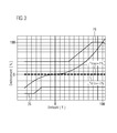
- the negative, static current limit 26 is also shown in the diagram FIG. 3 to recognize.
- the rotational speed n is plotted along the abscissa, the torque J or its nominal value J * along the ordinate, in each case standardized to 100% at nominal operation.
- the maximum achievable braking torque is set to approximately -40% of the nominal torque. This limit applies throughout the fourth quadrant and in the third quadrant up to a speed above approximately -30% of the rated speed. Then the torque curve decreases from up to about -60% of the rated torque at about -45% of the rated speed and remains approximately constant below this value.
- FIG. 3 How to get out FIG. 3 can also be found in a similar form, an upper static current limit 28, but in FIG. 1 is not shown.
- This upper, static current limit 28 is located in the quadrants I (driven forward drive) and II (braked reverse drive).
- the upper current limiting unit 24 and the lower current limiting unit 25 ensure that the output signal of the speed controller 17 is limited to a static "window", within which the output-side current setpoint value J *, which is passed on to the current controller 15, has to remain. There is therefore a static "window” between the two static current limits given in this way, in which the current setpoint value J * can be set freely during normal driving within the scope of the speed control. In normal operation, the static current limits 26, 28 are rarely reached.
- the actual speed value n as well as the current current setpoint value J * are fed, in addition to the current controller 15, by the speed controller 17 as a calculated value J * to the input side of a module 29 for determining additional limit values J * max and / or J * min for the current setpoint value J * are also performed in the form of signals 30, 31 to one of the two current value limiting units 24, 25. Since the additional limit values J * max and / or J * min for the current setpoint J * are determined by the module 29 as a function of the speed setpoint n *, the actual speed value n and the torque setpoint J *, they should be set as a positive dynamic limit value J * max and are referred to as the negative dynamic limit J * min .
- FIG. 2 On the left side, the input variables of the module 29, namely the speed setpoint n *, the actual speed value n and the torque or current setpoint value J *, can be seen on the right side of its output variables, namely the positive, dynamic current limit J * max on the one hand and the negative , dynamic current limit J * min on the other hand, which lt.
- FIG. 1 each one of the two current value limiting units 24, 25 are supplied.
- the output signals Q H and Q L of the Schmitt trigger module 32 connected to the speed setpoint input n * are each connected to the set input S of a static binary value memory 35, 36 - also referred to as bistable flip-flop or RS flip-flop.
- a high level at this input S of the respective binary value memory 35, 36 of the relevant output Q is set to high or logic '1' and then remains in this state, even if the input signal S returns to the low level, namely until a high level is applied to the relevant reset input R.
- the output signals Q of the two binary value memories 35, 36 are in turn connected to the control input of one (preferably electronically realized) switch 37, 38.
- These two switches 37, 38 each have two inputs, but only one exit.
- the output signal of the change-over switch 37 corresponds to the positive, dynamic current limit J * max
- the output signal of the changeover switch 38 corresponds to the negative, dynamic current limit J * min .
- the switches 37, 38 have at the input each a normally closed contact whose input signal is turned on at a low level at the control input to the respective output J * max , J * min , and a normally open contact whose input signal at a high level at the control input to the respective output J * max , J * min is switched through.
- the binary value memory 35 is designed to be S-dominant, ie in any case jumps to high or logic '1' at a high level at the set input S regardless of the level at the reset input R, this requires in each case that the speed setpoint n * is close to 0 or negative, ie less than the input signal M 1 .
- the Q L outputs of the two blocks 33, 34 are connected to one input of an AND gate 42 whose output is connected to the reset input R of the binary value memory 35. Therefore, if both the speed n and the torque or current setpoint J * in the L range, ie below the respective lower switching threshold (equivalent to driven drive in the reverse direction), the binary value memory 35 is reset if the speed setpoint n * anyway is not in its H range - better in its L range - is, so that the set input S of this binary value memory 35 is at logic '0'.
- the inverter and / or power converter via the electric motor drive the propeller only in the forward direction.
- the inverter and / or power converter via the electric motor drive the propeller only in the reverse direction.
- this switching state is not desirable when the speed setpoint n * is 0 or near 0 and the turbine-powered propeller over the Electric motor from the converter and / or power converter not stopped, that can be held torqueless, but is braked.
- the integrated therein component 32 has an additional Q M output, which only generates a high level when the speed setpoint n * is just in the area M, ie between the two switching thresholds of the Schmitt trigger 32.
- This signal Q M is supplied together with the output signals Q of the two binary value memories 35, 36 each to an input of an AND gate 43. Its output signal therefore only assumes a high level when the ship's propulsion system is to be stopped and the propeller, possibly driven by the turbine effect, is to be held momentless over the electric motor by the converter and / or converter.
Landscapes
- Engineering & Computer Science (AREA)
- Chemical & Material Sciences (AREA)
- Combustion & Propulsion (AREA)
- Mechanical Engineering (AREA)
- Ocean & Marine Engineering (AREA)
- Radar, Positioning & Navigation (AREA)
- Remote Sensing (AREA)
- Electric Propulsion And Braking For Vehicles (AREA)
- Control Of Electric Motors In General (AREA)
Applications Claiming Priority (2)
| Application Number | Priority Date | Filing Date | Title |
|---|---|---|---|
| DE102008032023 | 2008-07-07 | ||
| DE102008036483A DE102008036483A1 (de) | 2008-07-07 | 2008-08-05 | Verfahren und Vorrichtung zur Steuerung des Propellerschubes eines elektrisch angetriebenen Schiffsantriebssystems |
Publications (2)
| Publication Number | Publication Date |
|---|---|
| EP2143632A2 true EP2143632A2 (fr) | 2010-01-13 |
| EP2143632A3 EP2143632A3 (fr) | 2012-11-07 |
Family
ID=41210650
Family Applications (1)
| Application Number | Title | Priority Date | Filing Date |
|---|---|---|---|
| EP09163542A Withdrawn EP2143632A3 (fr) | 2008-07-07 | 2009-06-24 | Procédé et dispositif de commande de poussée d'hélices d'un système d'entraînement de bateau entraîné électriquement |
Country Status (2)
| Country | Link |
|---|---|
| EP (1) | EP2143632A3 (fr) |
| DE (1) | DE102008036483A1 (fr) |
Cited By (2)
| Publication number | Priority date | Publication date | Assignee | Title |
|---|---|---|---|---|
| EP3321171A1 (fr) * | 2016-11-14 | 2018-05-16 | Yamaha Hatsudoki Kabushiki Kaisha | Appareil de propulsion de navire, navire le comprenant et procédé de commande d'un appareil de propulsion de navire |
| CN114995115A (zh) * | 2022-05-24 | 2022-09-02 | 中国船舶重工集团公司第七0三研究所无锡分部 | 用于气垫船机桨的匹配控制方法及装置 |
Families Citing this family (1)
| Publication number | Priority date | Publication date | Assignee | Title |
|---|---|---|---|---|
| DE102021201901A1 (de) | 2021-03-01 | 2022-09-01 | Robert Bosch Gesellschaft mit beschränkter Haftung | Verfahren zum Betreiben einer elektrischen Maschine, Vorrichtung zum Betreiben einer elektrischen Maschine, elektrische Maschine |
Family Cites Families (8)
| Publication number | Priority date | Publication date | Assignee | Title |
|---|---|---|---|---|
| DE4428685C2 (de) * | 1994-08-12 | 1997-01-16 | Berg Claus C Univ Prof Dr | Verfahren und Vorrichtung zum Verteilen von Waren |
| DE10011609C2 (de) * | 1999-06-24 | 2002-11-07 | Siemens Ag | Antriebseinrichtung für Schiffspropeller |
| EP1187760B1 (fr) * | 1999-06-24 | 2004-04-14 | Siemens Aktiengesellschaft | Systeme d'entrainement et de propulsion pour bateaux |
| DE10063086A1 (de) * | 2000-01-14 | 2001-08-23 | Siemens Ag | Schiffsantriebssystem mit in der Dynamik angepasster Regelung |
| DE10011604A1 (de) * | 2000-03-10 | 2001-10-04 | Infineon Technologies Ag | Polybenzoxazol-Vorstufen |
| US7236937B2 (en) * | 2000-06-27 | 2007-06-26 | Siemens Dematic Ag | Method for consigning ordered commodities |
| DE10034858A1 (de) * | 2000-07-18 | 2002-02-07 | Trade5 De Gmbh | Verfahren zur Beförderung von Sendungen |
| EP2062813B1 (fr) * | 2007-11-23 | 2012-07-25 | Siemens Aktiengesellschaft | Procédé et dispositif destinés à l'arrêt aussi rapide que possible des hélices entraînées électriquement d'un bateau |
-
2008
- 2008-08-05 DE DE102008036483A patent/DE102008036483A1/de not_active Withdrawn
-
2009
- 2009-06-24 EP EP09163542A patent/EP2143632A3/fr not_active Withdrawn
Non-Patent Citations (1)
| Title |
|---|
| None |
Cited By (3)
| Publication number | Priority date | Publication date | Assignee | Title |
|---|---|---|---|---|
| EP3321171A1 (fr) * | 2016-11-14 | 2018-05-16 | Yamaha Hatsudoki Kabushiki Kaisha | Appareil de propulsion de navire, navire le comprenant et procédé de commande d'un appareil de propulsion de navire |
| US10167067B2 (en) | 2016-11-14 | 2019-01-01 | Yamaha Hatsudoki Kabushiki Kaisha | Vessel propulsion apparatus and vessel including the same |
| CN114995115A (zh) * | 2022-05-24 | 2022-09-02 | 中国船舶重工集团公司第七0三研究所无锡分部 | 用于气垫船机桨的匹配控制方法及装置 |
Also Published As
| Publication number | Publication date |
|---|---|
| EP2143632A3 (fr) | 2012-11-07 |
| DE102008036483A1 (de) | 2010-02-11 |
Similar Documents
| Publication | Publication Date | Title |
|---|---|---|
| EP1246754B1 (fr) | Systeme de propulsion pour bateau muni d'une regulation adaptee a la dynamique | |
| DE3414592C2 (fr) | ||
| DE2733078C2 (fr) | ||
| EP2616327A1 (fr) | Procédé pour faire fonctionner un navire, en particulier un cargo, pourvu d'au moins un rotor à effet magnus | |
| DE3207398A1 (de) | Schiffspropulsionsanlage mit einem haupt- und einem zusatzpropeller | |
| EP2143632A2 (fr) | Procédé et dispositif de commande de poussée d'hélices d'un système d'entraînement de bateau entraîné électriquement | |
| DE3539617A1 (de) | Vorrichtung zur steuerung eines zykloidenpropellers fuer schiffe | |
| EP2062813B1 (fr) | Procédé et dispositif destinés à l'arrêt aussi rapide que possible des hélices entraînées électriquement d'un bateau | |
| EP2668091B1 (fr) | Système d'entraînement électrique pour navire et procédé permettant de faire fonctionner un système d'entraînement de ce type | |
| EP0714162A2 (fr) | Circuit de commande d'une moteur commuté électroniquement | |
| DE102008046292A1 (de) | Schiffsantrieb für ein Wasserfahrzeug | |
| DE3741581A1 (de) | Elektrische lenkhilfevorrichtung mit motorbremsfunktion | |
| DE1942667B2 (de) | Verfahren zur Lastregelung von Schiffsmotoren und Anordnung zur Durchführung des Verfahrens | |
| DE10063086A1 (de) | Schiffsantriebssystem mit in der Dynamik angepasster Regelung | |
| EP2986502B1 (fr) | Optimisation d'un système d'entraînement comprenant une hélice à pas variable sur un véhicule maritime au cours d'une manuvre d'arrêt | |
| DE10011601C2 (de) | Antriebseinrichtung für Schiffspropeller | |
| DE1463654B2 (de) | Impulsgesteuerter umschaltbarer gleichstrommotor | |
| AT391964B (de) | Verfahren und vorrichtung zum betrieb einer stromrichtergespeisten drehfeldmaschine mit stromeinpraegung und schlupfsteuerung | |
| EP0678971B1 (fr) | Méthode pour inverser la direction de rotation pour un moteur CC sans balai à plan régime et moteur CC sans balai | |
| DE2951839C2 (de) | Elektrischer Antrieb, insbesondere für Hebezeuge wie Aufzüge, Krane oder dergleichen | |
| EP1487095A1 (fr) | Procédé et dispositif pour freiner un moteur asynchrone à vitesse variable | |
| DD283535A7 (de) | Verfahren zur drehzahlregelung eines thyristorgespeisten gleichstrommotors in feldumkehrschaltung fuer den propellerantrieb von schiffen | |
| DE2816126C3 (de) | Verfahren zum Starten und Umsteuern einer gasturbo-elektrischen Antriebsanlage für eisbrechende Schiffe | |
| WO2010099860A1 (fr) | Système propulseur pour un bateau | |
| DE2316423A1 (de) | Schiffspropellerantrieb |
Legal Events
| Date | Code | Title | Description |
|---|---|---|---|
| PUAI | Public reference made under article 153(3) epc to a published international application that has entered the european phase |
Free format text: ORIGINAL CODE: 0009012 |
|
| AK | Designated contracting states |
Kind code of ref document: A2 Designated state(s): AT BE BG CH CY CZ DE DK EE ES FI FR GB GR HR HU IE IS IT LI LT LU LV MC MK MT NL NO PL PT RO SE SI SK TR |
|
| PUAL | Search report despatched |
Free format text: ORIGINAL CODE: 0009013 |
|
| AK | Designated contracting states |
Kind code of ref document: A3 Designated state(s): AT BE BG CH CY CZ DE DK EE ES FI FR GB GR HR HU IE IS IT LI LT LU LV MC MK MT NL NO PL PT RO SE SI SK TR |
|
| AX | Request for extension of the european patent |
Extension state: AL BA RS |
|
| RIC1 | Information provided on ipc code assigned before grant |
Ipc: B63H 21/17 20060101AFI20121002BHEP Ipc: B63H 21/22 20060101ALI20121002BHEP |
|
| RAP1 | Party data changed (applicant data changed or rights of an application transferred) |
Owner name: SIEMENS AKTIENGESELLSCHAFT |
|
| 17P | Request for examination filed |
Effective date: 20130507 |
|
| STAA | Information on the status of an ep patent application or granted ep patent |
Free format text: STATUS: THE APPLICATION IS DEEMED TO BE WITHDRAWN |
|
| 18D | Application deemed to be withdrawn |
Effective date: 20170103 |