EP2143882A2 - Procédé et appareil pour fournir un refroidissement par film d'air pour des composants de turbine - Google Patents
Procédé et appareil pour fournir un refroidissement par film d'air pour des composants de turbine Download PDFInfo
- Publication number
- EP2143882A2 EP2143882A2 EP09164867A EP09164867A EP2143882A2 EP 2143882 A2 EP2143882 A2 EP 2143882A2 EP 09164867 A EP09164867 A EP 09164867A EP 09164867 A EP09164867 A EP 09164867A EP 2143882 A2 EP2143882 A2 EP 2143882A2
- Authority
- EP
- European Patent Office
- Prior art keywords
- cooling gas
- turbine
- opening
- feed aperture
- cooling
- Prior art date
- Legal status (The legal status is an assumption and is not a legal conclusion. Google has not performed a legal analysis and makes no representation as to the accuracy of the status listed.)
- Withdrawn
Links
Images
Classifications
-
- F—MECHANICAL ENGINEERING; LIGHTING; HEATING; WEAPONS; BLASTING
- F01—MACHINES OR ENGINES IN GENERAL; ENGINE PLANTS IN GENERAL; STEAM ENGINES
- F01D—NON-POSITIVE DISPLACEMENT MACHINES OR ENGINES, e.g. STEAM TURBINES
- F01D5/00—Blades; Blade-carrying members; Heating, heat-insulating, cooling or antivibration means on the blades or the members
- F01D5/12—Blades
- F01D5/14—Form or construction
- F01D5/18—Hollow blades, i.e. blades with cooling or heating channels or cavities; Heating, heat-insulating or cooling means on blades
- F01D5/186—Film cooling
-
- F—MECHANICAL ENGINEERING; LIGHTING; HEATING; WEAPONS; BLASTING
- F05—INDEXING SCHEMES RELATING TO ENGINES OR PUMPS IN VARIOUS SUBCLASSES OF CLASSES F01-F04
- F05D—INDEXING SCHEME FOR ASPECTS RELATING TO NON-POSITIVE-DISPLACEMENT MACHINES OR ENGINES, GAS-TURBINES OR JET-PROPULSION PLANTS
- F05D2260/00—Function
- F05D2260/20—Heat transfer, e.g. cooling
- F05D2260/202—Heat transfer, e.g. cooling by film cooling
-
- Y—GENERAL TAGGING OF NEW TECHNOLOGICAL DEVELOPMENTS; GENERAL TAGGING OF CROSS-SECTIONAL TECHNOLOGIES SPANNING OVER SEVERAL SECTIONS OF THE IPC; TECHNICAL SUBJECTS COVERED BY FORMER USPC CROSS-REFERENCE ART COLLECTIONS [XRACs] AND DIGESTS
- Y02—TECHNOLOGIES OR APPLICATIONS FOR MITIGATION OR ADAPTATION AGAINST CLIMATE CHANGE
- Y02T—CLIMATE CHANGE MITIGATION TECHNOLOGIES RELATED TO TRANSPORTATION
- Y02T50/00—Aeronautics or air transport
- Y02T50/60—Efficient propulsion technologies, e.g. for aircraft
-
- Y—GENERAL TAGGING OF NEW TECHNOLOGICAL DEVELOPMENTS; GENERAL TAGGING OF CROSS-SECTIONAL TECHNOLOGIES SPANNING OVER SEVERAL SECTIONS OF THE IPC; TECHNICAL SUBJECTS COVERED BY FORMER USPC CROSS-REFERENCE ART COLLECTIONS [XRACs] AND DIGESTS
- Y10—TECHNICAL SUBJECTS COVERED BY FORMER USPC
- Y10T—TECHNICAL SUBJECTS COVERED BY FORMER US CLASSIFICATION
- Y10T29/00—Metal working
- Y10T29/49—Method of mechanical manufacture
- Y10T29/49316—Impeller making
- Y10T29/4932—Turbomachine making
- Y10T29/49321—Assembling individual fluid flow interacting members, e.g., blades, vanes, buckets, on rotary support member
Definitions
- This invention relates generally to turbines and more specifically, to providing film cooling for turbines.
- Turbines are utilized in a variety of aviation, industrial, and power generation applications.
- a turbine in general may be a rotating device that utilizes the action of a fluid, such as one or more hot gases, on it to produce work.
- a fluid such as one or more hot gases
- one or more pressurized, high temperature gases are typically utilized as the driving force of the gas turbine.
- a typical gas turbine includes three major components: a compressor, a combustor, and a turbine.
- the compressor compresses incoming air (or gas) to a high pressure and the combustor ignites fuel and mixes the fuel with the high pressure air to produce a high temperature, high velocity gas.
- the turbine then typically extracts energy from the high temperature, high velocity gas as one or more sets of rotating turbine blades are rotated by the gas.
- the turbine operating temperatures are typically increased.
- the use of higher temperature gases in the conventional gas turbines generally yields higher energy potential.
- various components of the gas turbine situated in or along the hot gas path often experience extremely high thermal loading.
- the turbine blades utilized in the turbine may be damaged or degraded by continuous exposure to the hot gases.
- the temperature of the gases is higher than the melting points associated with the materials utilized in the construction of the turbine blades.
- various internal and external cooling techniques may be employed in an effort to control and lower the temperature of the components of the turbine within or along the hot gas path, such as the turbine blades.
- internal cooling relatively cold air is typically bypassed from the compressor, other turbine component, or received from an external source and passed through one or more hollow passages inside a turbine component within the hot gas path.
- external cooling also referred to as film cooling
- relatively cold air is typically received from the compressor, other turbine component or, an external source and passed or exited out through small holes at discrete locations along the surface of a turbine component within the hot gas path. This relatively cold air creates a protective blanket that protects the turbine component within the hot gas path from the high temperature environment.
- the turbine components with the hot gas path are typically cooled by providing one or more internal passages within the turbine component (or by constructing the component to include one or more hollow compartments) and then creating one or more slots between the internal passages and the surface of the component that is exposed to the hot gas path.
- the relatively cold cooling air is typically provided to the internal passages or hollow compartments from where it is then exited through the one or more slots.
- the relatively cold air exiting from the one or more slots is often at a much lower temperature than the hot gas that is driving the turbine.
- the introduction of the relatively cold air often directly leads to degradation in the efficiency of the turbine.
- Various conventional metered apertures, used for regulating the amount of air through a slot have been developed to increase the film coverage.
- these conventional metered apertures are typically angled against the surface of a slot, causing the relatively cool air to impinge on the back surface of the slot and leading to increased turbulence inside the slot. This turbulence makes it difficult for the relatively cold air to achieve uniformity before exiting into the hot gas path.
- cooling passages for providing cooling air or a cooling gas to a component of a turbine within a hot gas path. Additionally, there is a need for improved methods for providing cooling passages to facilitate more effective film cooling of turbine components subjected to a hot gas path.
- a cooling gas flow passage for use with a turbine.
- the cooling gas flow passage includes at least one feed aperture operable to receive cooling gas from at least one cooling gas compartment associated with a turbine component.
- the cooling gas flow passage also includes at least one slot with a converging portion having a first opening and a second opening, where the first opening receives the cooling gas from the feed aperture, and the second opening provides the cooling gas to at least a portion of an outer surface of the turbine component.
- a turbine component that is cooled.
- the turbine component includes an outer surface adapted to be exposed to a hot gas stream and an inner surface adapted to define at least a portion of a cooling gas compartment for receiving a cooling gas.
- At least one aperture is formed between the inner surface and the outer surface.
- the at least one aperture includes a feed aperture operable to receive the cooling gas from the cooling gas compartment.
- the at least one aperture further includes a slot having a converging portion and a diverging portion, where the converging portion receives the cooling gas from the feed aperture and provides at least a portion of the cooling gas to the diverging portion, and where the diverging portion receives the portion of cooling gas from the converging portion and provides the portion of cooling gas to the outer surface.
- a method for providing a cooling gas to a turbine component exposed to a hot gas flow is disclosed.
- a feed is formed, where the feed aperture is operable to receive cooling gas from a cooling gas compartment associated with the turbine component.
- a slot is formed that includes a converging portion with a first opening and a second opening. The first opening receives the cooling gas from the feed aperture, and the second opening provides at least a portion of the cooling gas to an outer surface of the turbine component.
- Cooling gas flow passages may be utilized in accordance with various embodiments of the invention in order to cool turbine components that are within a hot gas path.
- a turbine component may include one or more internal compartments, also referred to as cooling gas compartments that receive a cooling gas from a cooling gas source. Cooling gas flow passages may then facilitate film cooling of the turbine components.
- the cooling gas flow passages may include at least one feed aperture operable to receive cooling gas from the cooling gas compartments and at least one slot.
- the at least one slot may include a converging portion with a first opening and a second opening, wherein the first opening receives the cooling gas from the feed aperture, and wherein the second opening provides the cooling gas to at least a portion of an outer surface of a turbine component.
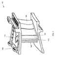
- FIG. 1 is a perspective view of one example of a turbine component that may be utilized in association with various embodiments of the invention.
- FIG. 1 illustrates one example of a turbine blade 100 that may be utilized in a gas turbine engine (not shown).
- the gas turbine engine may include three major components: a compressor, a combustion chamber and a turbine (none shown).
- the compressor may compress incoming gas, such as air, to a relatively high pressure
- the combustor may ignite fuel and mix the fuel with the relatively high pressure gas to produce a relatively high temperature, relatively high velocity gas, which is referred to herein as "hot gas.”
- the turbine may include a plurality of turbine blades, such as the turbine blade 100 that are mounted on a periphery of a rotor (not shown). The rotor may rotate due to the momentum of the hot gas coming out or exiting from the combustion chamber and impinging on the plurality of turbine blades 100.
- FIG. 1 further illustrates an airfoil surface 102 of the turbine blade 100 which may be one of two surfaces of the turbine blade 100.
- the other surface (not shown) of the turbine blade 100 may be opposite to the airfoil surface 102.
- the airfoil surface 102 may also be referred to as a pressure surface or outer surface, and the other surface of the turbine blade 100 may also be referred to as a suction surface.
- the terms "airfoil surface,” “pressure surface,” and “outer surface” may be utilized interchangeably.
- relatively hot gas from the combustion chamber may contact the turbine blade 100 at a leading edge 104 and flow over both the pressure surface 102 and the suction surface (not shown) of the turbine blade 100.
- the relatively hot gas may then exit from a trailing edge 106.
- the stream of relatively hot gas from the combustor may be divided into two separate paths at the leading edge 104 of the turbine blade 100, after which the streams flow over either surfaces of the turbine blade 100 respectively.
- the stream that flows over the suction surface may travel a larger distance as compared to the stream that flows over the pressure surface 102.
- the velocity of one stream relative to another may depend on the difference in the length of between the surfaces. Thus, the stream that flows over the suction surface may flow at a higher velocity as compared to the stream that flows over the pressure surface 102.
- the corresponding pressures on both the surfaces are inversely related, which may result in a higher pressure area on the pressure surface 102 as compared to a lower pressure area on the suction surface. This difference in pressure may result in a net force being applied on the turbine blade 100. Since the plurality of turbine blades 100 experience similar flow, these turbine blades 100 may be arranged circumferentially around the rotor in a manner such that the individual forces on the plurality of turbine blades 100 add up to give a net zero force and a net nonzero torque on the rotor. This torque may impart momentum to the rotor that facilitates the rotation of the rotor.
- the momentum extracted at the turbine stage may be determined based at least in part on the temperature of the hot gas.
- An increase in the operating temperature of the gas turbine may increase the power and efficiency of the gas turbine.
- the turbine blades 100 placed along the hot gas path may be vulnerable to the hot gas and may experience relatively high thermal loading as they are exposed to a continuous flow of relatively hot gas.
- the relatively hot gas may have a temperature between approximately 850°C and approximately 1700°C, although other temperatures and/or temperature ranges may be utilized as desired in other embodiments of the invention.
- the temperature of the relatively hot gases may be above the melting point of the materials utilized to construct the turbine blades 100 and/or other turbine components within the hot gas path.
- a film cooling technique may be employed to bring down, reduce, or otherwise control the temperature of one or more turbine components, such as the turbine blades 100, within the hot gas path.
- the temperature of the turbine components may be controlled as desired in various embodiments of the invention. For example, the temperature of the turbine components within the hot gas path may be reduced or brought down below the melting point of the materials utilized to construct the turbine.
- cooling gas such as cooling air
- a cooling gas e.g., air
- This flow of cooling gas may be passed to a hollow compartment or a cooling gas compartment of a turbine component, such as turbine blade 100, where it is ejected or emitted via one of cooling gas flow passages made in the turbine component.
- the ejected cooling gas may form a thin film of relatively cool gas over a surface of the turbine component that is exposed to the relatively hot gas.
- the ejecting cooling gas may assist in protecting the turbine component from the extreme temperatures of the relatively hot gas.
- an upper surface 108 may act as a base of the turbine blade 100 and may provide support to the pressure surface 102.
- a cooling gas compartment 110 may be seen on the upper surface 108.
- the turbine blade 100 may include any number of cooling gas compartments 110.
- Each cooling gas compartment 110 may be an internal hollow compartment situated or formed within the turbine blade 100.
- One or more cooling gas flow passages 112 may be formed between the cooling gas compartment 110 and one or more surfaces of the turbine blade 100 that are within the hot gas path. In this regard, relatively cool gas may be emitted from the cooling gas compartment 110 to the hot gas path in order to provide external film cooling for the turbine blade 100.
- the cooling gas compartment 110 may receive cooling gas at a relatively low temperature.
- a gas pump (not shown in the figure) may withdraw cooling gas, such as cooling air directly from the compressor.
- the cooling gas compartment 110 may facilitate the pressurization of the cooling gas so that the cooling gas has the necessary energy to be emitted through the one or more cooling gas passages and into the hot gas path.
- the cooling gas may be withdrawn from the cooling gas compartment 110 via one or more feed aperture. Each feed aperture may provide the cooling gas to an expansion cavity. After passing or flowing through the expansion cavity, the cooling gas may be provided to a slot that facilitates emitting the cooling gas into the hot gas path.
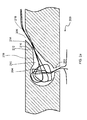
- FIG. 2a is a cross-sectional view of one embodiment of a cooling gas flow passage 200, according to an illustrative embodiment of the invention.
- any number of cooling gas flow passages such as cooling gas flow passage 200, may be provided for a turbine component, such as the turbine blade 100 illustrated in FIG. 1 .
- the cooling gas flow passage 200 may include a feed aperture 202, an expansion cavity 204, and a slot 206.
- the feed aperture 202 may receive cooling gas from a cooling gas compartment, such as cooling gas compartment 110 illustrated in FIG. 1 , and the feed aperture 202 may provide the cooling gas to the expansion cavity 204.
- the feed aperture 202 may be a mechanical device that meters and/or channelizes the flow of cooling gas that is received from the cooling gas compartment 110 and provided to the hot gas flow path via the cooling gas flow passage 200.
- a metering device may be a device with a minimum area that facilitates the control of the amount of gas flowing through it. Thus, the sum of all such minimum areas for all the feed apertures 202 provided for a turbine component may control the total amount of the cooling gas provided to the hot gas path for the turbine component.
- one or more cooling gas flow passages may facilitate the uniform spreading of the cooling gas provided to the hot gas path over one or more substantially entire surface of the turbine component, such as the pressure surface 102 illustrated in FIG. 1 .
- the expansion cavity 204 may be provided to facilitate imparting a swirl to the cooling gas received from a feed aperture 202.
- the swirl may facilitate diffusion of the cooling gas inside or within the expansion cavity 204.
- the cooling gas may be uniformly spread along the length of the expansion cavity 204.
- the uniform expansion may also be associated with the formation of secondary flows of the cooling gas within or inside the expansion cavity 204.
- the expansion cavity may be discontinuous in order to reduce or minimize the turbulence in the cooling gas.
- the expansion cavity 204 may be continuous in order to maintain and/or control the uniformity in the cooling gas.
- the cooling gas may be provided to a surface of a turbine component, such as turbine blade 100 from the expansion cavity 204 via one or more slots 206. If relatively turbulent gas is provided to the hot gas path, turbulence may be introduced in the boundary layer of the main gas flow leading to flow separation from an outer surface of a turbine component, such as the outer surface 102 illustrated in FIG. 1 for the turbine blade 100. Separation of flow from the outer surface 102 may degrade the aerodynamics of the flow and may lead to a decrease in the efficiency of the film cooling.
- a converging portion 208 may be included in a slot 206 formed in the cooling gas flow passage 200.
- the converging portion 208 may include a first opening 210 and a second opening 212.
- the first opening 210 may receive the cooling gas from the feed aperture 202 and/or the expansion cavity 204.
- the second opening 212 may provide the received cooling gas to another portion, section, or component of the slot 206 or, alternatively, to at least a portion of an external or outer surface, such as the outer surface 102, of the turbine blade 100.
- the converging portion 208 may at least partially remove the turbulence in the cooling gas flowing through it.
- the converging portion 208 may also increase the speed of the cooling gas.
- the converging portion 208 may at least partially remove one or more of the secondary flows from the cooling gas and facilitate the normalization of the cooling gas flow.
- the normalized cooling gas flow may have a relatively higher tendency to adhere to the outer surface 102 which in turn may increase the efficiency of the film cooling.
- the second opening 212 of the converging portion 208 may be located at the end of the cooling gas flow passage 200 and the cooling gas may be ejected into the hot gas path at the end of converging portion 208 only.
- a diverging portion 214 may be provided in the cooling gas flow passage 200, and the diverging portion 214 may receive the cooling gas from the converging portion 208 and eject the cooling gas into the hot gas path.
- the diverging portion may include a first opening 216 and a second opening 218. The first opening 216 may receive the cooling gas from the second opening 212 of the converging portion 208, and the second opening 218 may provide the cooling gas to an outer surface 102 of a turbine component within the hot gas flow path.
- the diverging portion 214 may facilitate the control of the velocity or speed of the cooling gas that is provided to the hot gas path. By controlling the velocity of the cooling gas as it is provided to the hot gas path, relatively greater film coverage over the outer surface 102 may be achieved. In one embodiment of the invention, the diverging portion 214 may reduce the velocity of the cooling gas received from the converging portion 208 to a velocity that is approximately equal to the velocity of the gas in the hot gas flow path. Thus, if the cooling gas received from the converging portion 208 is at a higher velocity as compared to the velocity of the gas within the hot gas flow path, then the diverging portion 214 may reduce the velocity of the cooling gas to a velocity that is approximately equal to that of the gas in the hot flow gas path. This reduction in the velocity of the cooling gas may facilitate a relatively more efficient film cooling by separating the hot gas in the hot gas flow path from the outer surface 102 of the turbine component.
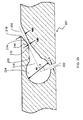
- FIG. 2b is a cross-sectional view of a cooling gas flow passage 201, according to an illustrative embodiment of the invention.
- the cooling gas passage 201 depicted in FIG. 2b may include similar components to the cooling gas flow passage 200 illustrated in FIG. 2a . Accordingly, like reference numerals may be utilized in describing the components of the two cooling gas flow passages 200, 201.
- the dimensions are provided with reference to a diameter D of the feed aperture 202.
- the cooling gas may enter a feed aperture 202 having a diameter D.
- the feed aperture 202 may be provided at an angle ⁇ relative to the direction of the slot 206.
- the angle ⁇ may facilitate the provision of proper flow of the cooling gas into the expansion cavity 204.
- the angle ⁇ between the feed aperture 202 and the slot 206 may be between approximately 30° and approximately 180°.
- the cooling gas may thereafter enter the expansion cavity 204.
- the expansion cavity 204 may have a diameter that is relatively larger than that of the feed aperture 202.
- the diameter of the expansion cavity 204 may be approximately two times to approximately eight times larger than that of the feed aperture 202.
- the diameter of the expansion cavity 204 may be approximately four times the diameter of the feed aperture 202, or approximately 4D.
- the relatively larger diameter of the expansion cavity 204 may facilitate the expansion and/or diffusion of the cooling gas received from the feed aperture 202.
- the cooling gas may then pass through the converging portion 208 and optionally through the diverging portion 214 (if included in an embodiment of the slot 206).
- the diameter of the first opening of the first opening 210 of the converging portion 208 may be larger than that of the second opening 212 or exit opening of the converging portion 208.
- the diameter of the first opening 210 of the converging portion 208 may be approximately two times to approximately four times the diameter of the feed aperture 202.
- the diameters of the second opening 212 of the converging portion 208 may be approximately 0.5 times to approximately 1.5 times the diameters of the feed aperture 202.
- the diameter of the first opening 210 of the converging portion 208 may be approximately three times the diameter of the feed aperture 202, or 3D, and the diameter of the second opening 212 of the converging portion 208 may be approximately 0.6 times the diameter of the feed aperture 202, or 0.6D.
- the relatively smaller diameter of the second opening 212 as compared to the diameter of the first opening 210 may facilitate acceleration to the cooling gas and at least partially remove the turbulence from the cooling gas flow.
- the converging portion 208 may facilitate the normalization of the cooling gas flow.
- the cooling gas may further pass through a diverging portion 214.
- the diverging portion 214 may have a first opening 216 and a second opening 218.
- the diameter of the first opening 216 may be approximately equal to or substantially similar to that of the diameter of the second opening 212 of the converging portion 208.
- the diameter of the second opening 218 of the diverging portion 214 may be greater than that of the first opening 216 of the diverging portion 214.
- the diameter of the second opening 218 may be approximately two times to approximately four times that of the diameter of the feed aperture 202.
- the diameter of the second opening 218 of the diverging portion 214 may be approximately 0.9 times that of the diameter of the feed aperture 202, or 0.9D. Given a diameter of the first opening 216 of approximately 0.6D, the diameter of the second opening 218 may be greater than that of the first opening 216.
- the diverging portion 214 may facilitate the deceleration and/or the reduction of velocity of the cooling gas. In some embodiments, the velocity of the cooling gas may be reduced to approximately the velocity of the hot gases within the hot gas flow path.
- varying lengths may be provided as desired for the converging portion 208 and the diverging portion 214.
- the length of the converging portion 208 may be approximately two times to approximately five times that of the feed aperture 202, and the length of the diverging portion 214 may be approximately two times to approximately five times that of the feed aperture 202.
- the length of the converging portion 208 may be approximately equal to the length of the diverging portion 214.
- varying overall lengths for the slot 206 may be provided.
- the length of the slot 206 may be approximately seven times to approximately ten times that of the feed aperture 202.
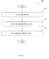
- FIG. 3 is a flowchart illustrating one example of a method 300 for providing cooling gas to a turbine component, in accordance with an illustrative embodiment of the invention. It will be apparent to a person skilled in the art that the following steps may be mechanical in nature and may be carried out and/or performed by any machining technique and/or combination of machining techniques as desired in various embodiments of the invention.
- the machining techniques used in forming the various components of the slot 206 may include but are not limited to laser drilling, water jet and EDM (electrical discharge machining).
- EDM electrical discharge machining
- the specific shape of the slots 206, the cooling gas flow passage 200 and the feed aperture 202 to be designed to spread gas flow or airflow over a greater surface area for effective film cooling may prove a major casting challenge owing to the complex geometry of the components involved.
- Processes such as EDM may use electrical discharge to make slots quickly and accurately, reach hard-to-access areas of part geometry and form the slots to a complex exit profile.
- laser drilling may use laser pulses while water jet machining may use a stream of water for machining the various components of the slots 206.
- the method 300 may begin at block 305.
- a feed aperture such as aperture 202, that is operable to receive cooling gas from a cooling gas compartment associated with a turbine component may be formed.
- the feed aperture 202 may be formed with a desired diameter that facilitates the metering and/or control of cooling gas flowing into and through the feed aperture 202.
- the cooling gas passing through the feed aperture 202 may enters an expansion cavity, such as cavity 204 where the cooling gas may be diffused.
- the expansion cavity may optionally be formed in the method 300.
- a converging portion of a slot such as converging portion 208 illustrated in FIG. 2a , may be formed and/or provided.
- cooling gas exiting the expansion cavity 204 and/or the feed aperture 202 may enter the converging portion 208, and the cooling gas may be accelerated and turbulence associated with the cooling gas may be reduced and/or minimized.
- operations may continue at block 315.
- a diverging portion of a slot such as diverging portion 214 illustrated in FIG. 2a , may be formed and/or provided.
- the diverging portion 214 may facilitate the control of the velocity of the cooling gas that is provided to an outer surface of a turbine component within the hot gas path.
- the diverging portion 214 may reduce and/or minimize the velocity of the cooling gas that is received from a corresponding converging portion of the slot.
- the velocity of the cooling gas may be controlled by the diverging portion to be approximately equal to the velocity of the relatively hot gas in the hot gas path flow.
- the diverging portion 206 may be formed.
- the method 300 may end following block 315.
- Film cooling may be used to protect the turbine components of a turbine from the high temperature of the hot gas coming out of the combustion chamber.
- the mechanism of film cooling may involve bleeding cooling gas, such as cooling air, from the compressor stage to the components in the turbine.
- a controlled amount of relatively cool gas may be allowed to bleed in order to maintain the efficiency of the turbine.
- specially prepared slots with a converging portion may be used to achieve the desired film cooling.
- the converging slots may facilitate uniformity in the relatively cool gas bled out while simultaneously maintaining a clean flow free from secondary vortices and adhering to the surface of the turbine component.
- the slots may include a diverging portion which facilitates the control of the velocity of the relatively cool gas that is provided to the surface of a turbine component.
- Certain embodiments of the invention are applicable for any device, which is exposed to the hot gas flow and may be cooled from the backside of a surface that is exposed to the hot gases.
- Some examples of such devices include but are not limited to combustion chambers, rocket nozzles, etc. It will be apparent that any example taken provided in the foregoing specification is merely provided for explanation purposes and does not limit the scope of the invention by any means.
Landscapes
- Engineering & Computer Science (AREA)
- Mechanical Engineering (AREA)
- General Engineering & Computer Science (AREA)
- Turbine Rotor Nozzle Sealing (AREA)
Applications Claiming Priority (1)
| Application Number | Priority Date | Filing Date | Title |
|---|---|---|---|
| US12/170,673 US20100008759A1 (en) | 2008-07-10 | 2008-07-10 | Methods and apparatuses for providing film cooling to turbine components |
Publications (2)
| Publication Number | Publication Date |
|---|---|
| EP2143882A2 true EP2143882A2 (fr) | 2010-01-13 |
| EP2143882A3 EP2143882A3 (fr) | 2013-03-13 |
Family
ID=41119722
Family Applications (1)
| Application Number | Title | Priority Date | Filing Date |
|---|---|---|---|
| EP09164867A Withdrawn EP2143882A3 (fr) | 2008-07-10 | 2009-07-08 | Procédé et appareil pour fournir un refroidissement par film d'air pour des composants de turbine |
Country Status (4)
| Country | Link |
|---|---|
| US (1) | US20100008759A1 (fr) |
| EP (1) | EP2143882A3 (fr) |
| JP (1) | JP2010019259A (fr) |
| CN (1) | CN101624916A (fr) |
Cited By (2)
| Publication number | Priority date | Publication date | Assignee | Title |
|---|---|---|---|---|
| US9068472B2 (en) | 2011-02-24 | 2015-06-30 | Rolls-Royce Plc | Endwall component for a turbine stage of a gas turbine engine |
| EP3124745A1 (fr) * | 2015-07-29 | 2017-02-01 | General Electric Technology GmbH | Composant de turbomachine avec paroi refroidie par film |
Families Citing this family (11)
| Publication number | Priority date | Publication date | Assignee | Title |
|---|---|---|---|---|
| US9157328B2 (en) * | 2010-12-24 | 2015-10-13 | Rolls-Royce North American Technologies, Inc. | Cooled gas turbine engine component |
| US8807944B2 (en) * | 2011-01-03 | 2014-08-19 | General Electric Company | Turbomachine airfoil component and cooling method therefor |
| US9279330B2 (en) * | 2012-02-15 | 2016-03-08 | United Technologies Corporation | Gas turbine engine component with converging/diverging cooling passage |
| CN103046967A (zh) * | 2012-12-27 | 2013-04-17 | 中国燃气涡轮研究院 | 一种涡轮气冷叶片 |
| JP2016509651A (ja) * | 2013-01-25 | 2016-03-31 | アイルランド ピーターIRELAND, Peter | ターボ機械類用エネルギー効率改善装置 |
| US20150165569A1 (en) * | 2013-12-18 | 2015-06-18 | Petya M. Georgieva | Repair of turbine engine components using waterjet ablation process |
| KR101906948B1 (ko) * | 2013-12-19 | 2018-10-11 | 한화에어로스페이스 주식회사 | 터빈용 날개 |
| US10006371B2 (en) | 2014-09-15 | 2018-06-26 | United Technologies Corporation | Film hole with in-wall accumulator |
| US10975704B2 (en) * | 2018-02-19 | 2021-04-13 | General Electric Company | Engine component with cooling hole |
| US11156102B2 (en) | 2018-03-19 | 2021-10-26 | General Electric Company | Blade having a tip cooling cavity and method of making same |
| CN112554961A (zh) * | 2020-12-02 | 2021-03-26 | 中国航发沈阳发动机研究所 | 一种高压涡轮导向冷却叶片 |
Family Cites Families (26)
| Publication number | Priority date | Publication date | Assignee | Title |
|---|---|---|---|---|
| US3816022A (en) * | 1972-09-01 | 1974-06-11 | Gen Electric | Power augmenter bucket tip construction for open-circuit liquid cooled turbines |
| US4142824A (en) * | 1977-09-02 | 1979-03-06 | General Electric Company | Tip cooling for turbine blades |
| US4303374A (en) * | 1978-12-15 | 1981-12-01 | General Electric Company | Film cooled airfoil body |
| US4380906A (en) * | 1981-01-22 | 1983-04-26 | United Technologies Corporation | Combustion liner cooling scheme |
| US4601638A (en) * | 1984-12-21 | 1986-07-22 | United Technologies Corporation | Airfoil trailing edge cooling arrangement |
| DE3540942A1 (de) * | 1985-11-19 | 1987-05-21 | Mtu Muenchen Gmbh | Umkehrbrennkammer, insbesondere umkehrringbrennkammer, fuer gasturbinentriebwerke, mit mindestens einer flammrohrwandfilmkuehleinrichtung |
| US4669957A (en) * | 1985-12-23 | 1987-06-02 | United Technologies Corporation | Film coolant passage with swirl diffuser |
| US4676719A (en) * | 1985-12-23 | 1987-06-30 | United Technologies Corporation | Film coolant passages for cast hollow airfoils |
| US4726735A (en) * | 1985-12-23 | 1988-02-23 | United Technologies Corporation | Film cooling slot with metered flow |
| US4672727A (en) * | 1985-12-23 | 1987-06-16 | United Technologies Corporation | Method of fabricating film cooling slot in a hollow airfoil |
| US4650949A (en) * | 1985-12-23 | 1987-03-17 | United Technologies Corporation | Electrode for electrical discharge machining film cooling passages in an airfoil |
| GB2227965B (en) * | 1988-10-12 | 1993-02-10 | Rolls Royce Plc | Apparatus for drilling a shaped hole in a workpiece |
| US5405242A (en) * | 1990-07-09 | 1995-04-11 | United Technologies Corporation | Cooled vane |
| US5382133A (en) * | 1993-10-15 | 1995-01-17 | United Technologies Corporation | High coverage shaped diffuser film hole for thin walls |
| US5702232A (en) * | 1994-12-13 | 1997-12-30 | United Technologies Corporation | Cooled airfoils for a gas turbine engine |
| US5820343A (en) * | 1995-07-31 | 1998-10-13 | United Technologies Corporation | Airfoil vibration damping device |
| US6050777A (en) * | 1997-12-17 | 2000-04-18 | United Technologies Corporation | Apparatus and method for cooling an airfoil for a gas turbine engine |
| US6347660B1 (en) * | 1998-12-01 | 2002-02-19 | Howmet Research Corporation | Multipiece core assembly for cast airfoil |
| US6164912A (en) * | 1998-12-21 | 2000-12-26 | United Technologies Corporation | Hollow airfoil for a gas turbine engine |
| US6234755B1 (en) * | 1999-10-04 | 2001-05-22 | General Electric Company | Method for improving the cooling effectiveness of a gaseous coolant stream, and related articles of manufacture |
| US6368060B1 (en) * | 2000-05-23 | 2002-04-09 | General Electric Company | Shaped cooling hole for an airfoil |
| US6994521B2 (en) * | 2003-03-12 | 2006-02-07 | Florida Turbine Technologies, Inc. | Leading edge diffusion cooling of a turbine airfoil for a gas turbine engine |
| US6981846B2 (en) * | 2003-03-12 | 2006-01-03 | Florida Turbine Technologies, Inc. | Vortex cooling of turbine blades |
| US6955522B2 (en) * | 2003-04-07 | 2005-10-18 | United Technologies Corporation | Method and apparatus for cooling an airfoil |
| US7097417B2 (en) * | 2004-02-09 | 2006-08-29 | Siemens Westinghouse Power Corporation | Cooling system for an airfoil vane |
| US7334992B2 (en) * | 2005-05-31 | 2008-02-26 | United Technologies Corporation | Turbine blade cooling system |
-
2008
- 2008-07-10 US US12/170,673 patent/US20100008759A1/en not_active Abandoned
-
2009
- 2009-07-07 JP JP2009160321A patent/JP2010019259A/ja not_active Withdrawn
- 2009-07-08 EP EP09164867A patent/EP2143882A3/fr not_active Withdrawn
- 2009-07-10 CN CN200910159749A patent/CN101624916A/zh active Pending
Cited By (3)
| Publication number | Priority date | Publication date | Assignee | Title |
|---|---|---|---|---|
| US9068472B2 (en) | 2011-02-24 | 2015-06-30 | Rolls-Royce Plc | Endwall component for a turbine stage of a gas turbine engine |
| EP3124745A1 (fr) * | 2015-07-29 | 2017-02-01 | General Electric Technology GmbH | Composant de turbomachine avec paroi refroidie par film |
| US10655474B2 (en) | 2015-07-29 | 2020-05-19 | General Electric Technology Gmbh | Turbo-engine component having outer wall discharge openings |
Also Published As
| Publication number | Publication date |
|---|---|
| US20100008759A1 (en) | 2010-01-14 |
| EP2143882A3 (fr) | 2013-03-13 |
| JP2010019259A (ja) | 2010-01-28 |
| CN101624916A (zh) | 2010-01-13 |
Similar Documents
| Publication | Publication Date | Title |
|---|---|---|
| EP2143882A2 (fr) | Procédé et appareil pour fournir un refroidissement par film d'air pour des composants de turbine | |
| US10641099B1 (en) | Impingement cooling for a gas turbine engine component | |
| US11414999B2 (en) | Cooling hole with shaped meter | |
| EP3124746B1 (fr) | Procédé de refroidissement d'un composant de turbomachine et ledit composant | |
| US8657576B2 (en) | Rotor blade | |
| US8083485B2 (en) | Angled tripped airfoil peanut cavity | |
| US10767489B2 (en) | Component for a turbine engine with a hole | |
| US11313235B2 (en) | Engine component with film hole | |
| US10494939B2 (en) | Air shredder insert | |
| EP2568119B1 (fr) | Aube de turbine avec agencement de refroidissement du bord de fuite amélioré | |
| EP3061911A1 (fr) | Composant de moteur | |
| CN106837429B (zh) | 具有膜孔的用于燃气涡轮发动机的构件 | |
| CN106884683B (zh) | 利用薄膜冷却的发动机构件 | |
| JP2017082771A (ja) | タービンブレード | |
| CN107084005B (zh) | 燃气涡轮发动机后缘喷射孔 | |
| CN106468180A (zh) | 用于燃气涡轮发动机的发动机构件 |
Legal Events
| Date | Code | Title | Description |
|---|---|---|---|
| PUAI | Public reference made under article 153(3) epc to a published international application that has entered the european phase |
Free format text: ORIGINAL CODE: 0009012 |
|
| AK | Designated contracting states |
Kind code of ref document: A2 Designated state(s): AT BE BG CH CY CZ DE DK EE ES FI FR GB GR HR HU IE IS IT LI LT LU LV MC MK MT NL NO PL PT RO SE SI SK SM TR |
|
| PUAL | Search report despatched |
Free format text: ORIGINAL CODE: 0009013 |
|
| AK | Designated contracting states |
Kind code of ref document: A3 Designated state(s): AT BE BG CH CY CZ DE DK EE ES FI FR GB GR HR HU IE IS IT LI LT LU LV MC MK MT NL NO PL PT RO SE SI SK SM TR |
|
| RIC1 | Information provided on ipc code assigned before grant |
Ipc: F01D 5/18 20060101AFI20130207BHEP |
|
| STAA | Information on the status of an ep patent application or granted ep patent |
Free format text: STATUS: THE APPLICATION IS DEEMED TO BE WITHDRAWN |
|
| 18D | Application deemed to be withdrawn |
Effective date: 20130201 |