EP2143887A2 - Joint élastique pour queue d'aronde d'une aube - Google Patents
Joint élastique pour queue d'aronde d'une aube Download PDFInfo
- Publication number
- EP2143887A2 EP2143887A2 EP09164783A EP09164783A EP2143887A2 EP 2143887 A2 EP2143887 A2 EP 2143887A2 EP 09164783 A EP09164783 A EP 09164783A EP 09164783 A EP09164783 A EP 09164783A EP 2143887 A2 EP2143887 A2 EP 2143887A2
- Authority
- EP
- European Patent Office
- Prior art keywords
- spring seal
- leg
- tab
- sealing
- sealing slot
- Prior art date
- Legal status (The legal status is an assumption and is not a legal conclusion. Google has not performed a legal analysis and makes no representation as to the accuracy of the status listed.)
- Withdrawn
Links
- 238000007789 sealing Methods 0.000 claims abstract description 37
- 238000000034 method Methods 0.000 claims description 10
- 239000000463 material Substances 0.000 claims description 6
- XEEYBQQBJWHFJM-UHFFFAOYSA-N Iron Chemical compound [Fe] XEEYBQQBJWHFJM-UHFFFAOYSA-N 0.000 claims description 4
- 239000010941 cobalt Substances 0.000 claims description 3
- GUTLYIVDDKVIGB-UHFFFAOYSA-N cobalt atom Chemical compound [Co] GUTLYIVDDKVIGB-UHFFFAOYSA-N 0.000 claims description 3
- 229910000531 Co alloy Inorganic materials 0.000 claims description 2
- 229910000640 Fe alloy Inorganic materials 0.000 claims description 2
- 229910000990 Ni alloy Inorganic materials 0.000 claims description 2
- 229910001220 stainless steel Inorganic materials 0.000 claims description 2
- 239000010935 stainless steel Substances 0.000 claims 1
- 239000002826 coolant Substances 0.000 description 4
- XAGFODPZIPBFFR-UHFFFAOYSA-N aluminium Chemical compound [Al] XAGFODPZIPBFFR-UHFFFAOYSA-N 0.000 description 3
- 229910052782 aluminium Inorganic materials 0.000 description 3
- 238000001816 cooling Methods 0.000 description 3
- 229910045601 alloy Inorganic materials 0.000 description 1
- 239000000956 alloy Substances 0.000 description 1
- 239000011248 coating agent Substances 0.000 description 1
- 238000000576 coating method Methods 0.000 description 1
- 229910017052 cobalt Inorganic materials 0.000 description 1
- 239000012809 cooling fluid Substances 0.000 description 1
- 238000000151 deposition Methods 0.000 description 1
- 229910001026 inconel Inorganic materials 0.000 description 1
- 238000003754 machining Methods 0.000 description 1
- 238000004519 manufacturing process Methods 0.000 description 1
- 238000012986 modification Methods 0.000 description 1
- 230000004048 modification Effects 0.000 description 1
- 238000005096 rolling process Methods 0.000 description 1
- 229910000601 superalloy Inorganic materials 0.000 description 1
Images


Classifications
-
- F—MECHANICAL ENGINEERING; LIGHTING; HEATING; WEAPONS; BLASTING
- F01—MACHINES OR ENGINES IN GENERAL; ENGINE PLANTS IN GENERAL; STEAM ENGINES
- F01D—NON-POSITIVE DISPLACEMENT MACHINES OR ENGINES, e.g. STEAM TURBINES
- F01D11/00—Preventing or minimising internal leakage of working-fluid, e.g. between stages
- F01D11/005—Sealing means between non relatively rotating elements
- F01D11/006—Sealing the gap between rotor blades or blades and rotor
-
- F—MECHANICAL ENGINEERING; LIGHTING; HEATING; WEAPONS; BLASTING
- F01—MACHINES OR ENGINES IN GENERAL; ENGINE PLANTS IN GENERAL; STEAM ENGINES
- F01D—NON-POSITIVE DISPLACEMENT MACHINES OR ENGINES, e.g. STEAM TURBINES
- F01D5/00—Blades; Blade-carrying members; Heating, heat-insulating, cooling or antivibration means on the blades or the members
- F01D5/02—Blade-carrying members, e.g. rotors
- F01D5/08—Heating, heat-insulating or cooling means
- F01D5/081—Cooling fluid being directed on the side of the rotor disc or at the roots of the blades
-
- F—MECHANICAL ENGINEERING; LIGHTING; HEATING; WEAPONS; BLASTING
- F01—MACHINES OR ENGINES IN GENERAL; ENGINE PLANTS IN GENERAL; STEAM ENGINES
- F01D—NON-POSITIVE DISPLACEMENT MACHINES OR ENGINES, e.g. STEAM TURBINES
- F01D5/00—Blades; Blade-carrying members; Heating, heat-insulating, cooling or antivibration means on the blades or the members
- F01D5/30—Fixing blades to rotors; Blade roots ; Blade spacers
- F01D5/3007—Fixing blades to rotors; Blade roots ; Blade spacers of axial insertion type
-
- F—MECHANICAL ENGINEERING; LIGHTING; HEATING; WEAPONS; BLASTING
- F02—COMBUSTION ENGINES; HOT-GAS OR COMBUSTION-PRODUCT ENGINE PLANTS
- F02C—GAS-TURBINE PLANTS; AIR INTAKES FOR JET-PROPULSION PLANTS; CONTROLLING FUEL SUPPLY IN AIR-BREATHING JET-PROPULSION PLANTS
- F02C7/00—Features, components parts, details or accessories, not provided for in, or of interest apart form groups F02C1/00 - F02C6/00; Air intakes for jet-propulsion plants
- F02C7/28—Arrangement of seals
-
- F—MECHANICAL ENGINEERING; LIGHTING; HEATING; WEAPONS; BLASTING
- F16—ENGINEERING ELEMENTS AND UNITS; GENERAL MEASURES FOR PRODUCING AND MAINTAINING EFFECTIVE FUNCTIONING OF MACHINES OR INSTALLATIONS; THERMAL INSULATION IN GENERAL
- F16J—PISTONS; CYLINDERS; SEALINGS
- F16J15/00—Sealings
- F16J15/02—Sealings between relatively-stationary surfaces
- F16J15/06—Sealings between relatively-stationary surfaces with solid packing compressed between sealing surfaces
- F16J15/08—Sealings between relatively-stationary surfaces with solid packing compressed between sealing surfaces with exclusively metal packing
- F16J15/0887—Sealings between relatively-stationary surfaces with solid packing compressed between sealing surfaces with exclusively metal packing the sealing effect being obtained by elastic deformation of the packing
-
- F—MECHANICAL ENGINEERING; LIGHTING; HEATING; WEAPONS; BLASTING
- F05—INDEXING SCHEMES RELATING TO ENGINES OR PUMPS IN VARIOUS SUBCLASSES OF CLASSES F01-F04
- F05D—INDEXING SCHEME FOR ASPECTS RELATING TO NON-POSITIVE-DISPLACEMENT MACHINES OR ENGINES, GAS-TURBINES OR JET-PROPULSION PLANTS
- F05D2240/00—Components
- F05D2240/55—Seals
Definitions
- the present application relates generally to any type of turbine and more particularly relates to systems and methods for sealing a gap formed between a turbine bucket dovetail and a turbine rotor via a spring seal.
- Gas turbines generally include a turbine rotor (wheel) with a number of circumferentially spaced buckets (blades).
- the buckets generally may include an airfoil, a platform, a shank, a dovetail, and other elements.
- the dovetail of each bucket is positioned within the turbine rotor and secured therein.
- the airfoils project into the hot gas path so as to convert the kinetic energy of the gas into rotational mechanical energy.
- a number of cooling medium passages may extend radially through the bucket to direct an inward and/or an outward flow of the cooling medium therethrough.
- Leaks may develop in the coolant supply circuit based upon a gap between the tabs of the dovetails and the surface of the rotor due to increases in thermal and/or centrifugal loads. Air losses from the bucket supply circuit into the wheel space may be significant with respect to blade cooling medium flow requirements. Moreover, the air may be extracted from later compressor stages such that the penalty on energy output and overall efficiency may be significant during engine operation.
- one method involves depositing aluminum on a dovetail tab so as to fill the gap at least partially. Specifically, a circular ring may be pressed against the forward side of the dovetail face. Although this design seals well and is durable, the design cannot be easily disassembled and replaced in the field. Rather, these rings may only be disassembled when the entire rotor is disassembled.
- the present invention thus provides a spring seal system for a turbine dovetail tab.
- the spring seal system may include a sealing slot positioned about the tab and a spring seal positioned within the sealing slot.
- the spring seal may include a substantial "U" shape.
- the present invention further provides a spring seal system for a turbine dovetail tab.
- the spring seal system may include a sealing slot positioned about the tab and a spring seal positioned within the sealing slot.
- the sealing slot may define a first leg and a second leg.
- the spring seal may include an opening facing the second leg.
- the present invention further provides a method of sealing a gap between a dovetail tab and a rotor of a turbine.
- the method includes the steps of positioning a spring seal within a sealing slot of the dovetail tab, operating the turbine, and expanding the spring seal into the gap.
- Fig. 1A shows a bucket 10 as may be used herein.
- the bucket 10 may be a first or a second stage bucket as used in a 7FA+e gas turbine sold by General Electric Company of Schenectady, New York. Any other type of bucket or stage also may be used herein.
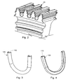
- the bucket 10 may be used with a rotor 20 as is shown in Fig. 2 .
- the bucket 10 may include an airfoil 30, a platform 40, a shank 50, a dovetail 60, and other elements. It will be appreciated that the bucket 10 is one of a number of circumferentially spaced buckets 10 secured to and about the rotor 20 of the turbine.
- the bucket 10 of Fig. 1A has a shroud 65 on one end of the airfoil 30.
- a bucket 11 of Fig. 1B lacks the shroud. Any other type of bucket design may be used herein.
- the rotor 20 may have a number of slots 25 for receiving the dovetails 60 of the buckets 10, 11.
- the airfoils 30 of the buckets 10, 11 project into the hot gas stream so as to enable the kinetic energy of the stream to be converted into mechanical energy through the rotation of the rotor 20.
- the dovetail 60 may include a first tang or tab 70 and a second tab 80 extending therefrom. Similar designs may be used herein.
- a gap 90 may be formed between the ends of the tabs 70, 80 of the dovetail 60 and the rotor 20. A high pressure cooling flow may escape via the gap 90 unless a sealing system of some type is employed.
- Figs. 3-6 show a spring seal 100 as is described herein.
- the spring seal has an axial opening 110 along one side thereof.
- the spring seal 100 is largely tube like in shape with a portion removed so as to form a substantial "C” shape along its cross-section.
- the spring seal 100 also may be in the form a substantial "U” shape so as to fit within the dovetail tab 70, 80.
- Other shapes and configurations may be used herein.
- the spring seal 100 may be made out of a high temperature resistant material with elastic characteristics. Examples include alloys of nickel, iron, or cobalt, various types of stainless steels, and other types of materials. An alloy may be a cobalt based super alloy such as Inconnel X-750, A-286, and similar materials.
- the spring seal 100 may be a single element or several sections may be joined together.
- the spring seal 100 may be made by rolling a sheet of material into a "C" shape and then forming the "C" shape into the final design such as the "U” shape shown. Alternatively, the spring seal 100 may be formed as a continuous ring which then may be milled to create the "C" cross-section and then cut in half to yield two (2) "U” shaped seals. The use of the "U” shape allows the spring seal 100 to be used with the tabs 70, 80 as will be described in more detail below.
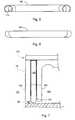
- Figs. 7 and 8 show a spring seal system 120 as is described herein.
- the spring seal system 120 may be positioned about and within the first tab 70 of the dovetail 60 of the bucket 10.
- the spring seal system 120 may include a sealing slot 130 positioned within the first tab 70.
- the sealing slot 130 may extend about the parameter of the first tab 70 in whole or in-part. The dimensions and shape of the sealing slot 130 may vary.
- the sealing slot 130 may be formed with conventional machining techniques or other types of manufacturing technique.
- the spring seal system 120 also may be used with the second tab 80 and elsewhere.
- the sealing slot 130 defines a first leg 140 and a second leg 150 within the tab 70 and with the sealing slot 130 therebetween.
- the first leg 140 may be positioned adjacent to a high pressure side 160 of the dovetail 60.
- the high pressure side 160 may provide the bucket cooling air supply.
- the second leg 150 may be positioned about a low pressure side 170, i.e., the wheel space.
- the spring seal 100 may be positioned within the sealing slot 130 of the spring seal system 120.
- the axial opening 110 may face the second leg 150 and the low pressure side 170.
- Other orientations and configurations of the spring seal 100 may be used herein.
- Fig. 9 shows an alterative embodiment of a spring seal 180.
- the spring seal 180 is similar to the spring seal 100 above but with a radial opening 190 along one side thereof. Specifically, a portion of the diameter is removed or is missing so as to form the radial opening 190.
- the spring seal 180 may be positioned within the sealing slot 130 in a manner similar to that described above.
- the spring seal 100, 180 may come in any shape or orientation including those in a substantial “E”, “W”, “V”, “O”, or other common seal shapes.
- the opening such as the axial opening 110, the radial opening 190, and the like, may be positioned either parallel to the leakage path or perpendicular to it. Other configurations also may be used herein.
- sealing system 100 thus reduces leakage through the gap 90. Sealing efficiency similar to that of the commonly used aluminum coating thus may be found and improved upon without the use of the aluminum material. The reduction of cooling flow leakage improves overall system efficiency.
- the spring seal system 120 may be used with other sealing systems and methods.
Landscapes
- Engineering & Computer Science (AREA)
- General Engineering & Computer Science (AREA)
- Mechanical Engineering (AREA)
- Chemical & Material Sciences (AREA)
- Combustion & Propulsion (AREA)
- Turbine Rotor Nozzle Sealing (AREA)
Applications Claiming Priority (1)
| Application Number | Priority Date | Filing Date | Title |
|---|---|---|---|
| US12/168,939 US8038405B2 (en) | 2008-07-08 | 2008-07-08 | Spring seal for turbine dovetail |
Publications (2)
| Publication Number | Publication Date |
|---|---|
| EP2143887A2 true EP2143887A2 (fr) | 2010-01-13 |
| EP2143887A3 EP2143887A3 (fr) | 2013-09-11 |
Family
ID=41130159
Family Applications (1)
| Application Number | Title | Priority Date | Filing Date |
|---|---|---|---|
| EP09164783.4A Withdrawn EP2143887A3 (fr) | 2008-07-08 | 2009-07-07 | Joint élastique pour queue d'aronde d'une aube |
Country Status (4)
| Country | Link |
|---|---|
| US (1) | US8038405B2 (fr) |
| EP (1) | EP2143887A3 (fr) |
| JP (1) | JP2010019261A (fr) |
| CN (1) | CN101644172A (fr) |
Cited By (3)
| Publication number | Priority date | Publication date | Assignee | Title |
|---|---|---|---|---|
| EP2505785A3 (fr) * | 2011-03-30 | 2013-05-01 | General Electric Company | Joint d'étanchéité pour queue d'aronde, procédé d'étanchéisation et ensemble associés |
| US8845272B2 (en) | 2011-02-25 | 2014-09-30 | General Electric Company | Turbine shroud and a method for manufacturing the turbine shroud |
| US10851661B2 (en) | 2017-08-01 | 2020-12-01 | General Electric Company | Sealing system for a rotary machine and method of assembling same |
Families Citing this family (12)
| Publication number | Priority date | Publication date | Assignee | Title |
|---|---|---|---|---|
| JP5446943B2 (ja) | 2010-01-29 | 2014-03-19 | ソニー株式会社 | 印刷システム及びプリンタ装置の制御方法 |
| US20120235366A1 (en) * | 2011-03-15 | 2012-09-20 | General Electric Company | Seal for turbine engine bucket |
| US20130028743A1 (en) * | 2011-07-26 | 2013-01-31 | General Electric Company | Systems, Methods, and Apparatus for Sealing a Bucket Dovetail in a Turbine |
| US8894378B2 (en) * | 2011-07-26 | 2014-11-25 | General Electric Company | Systems, methods, and apparatus for sealing a bucket dovetail in a turbine |
| FR2982635B1 (fr) * | 2011-11-15 | 2013-11-15 | Snecma | Roue a aubes pour une turbomachine |
| US9175573B2 (en) * | 2012-11-28 | 2015-11-03 | General Electric Company | Dovetail attachment seal for a turbomachine |
| US9416675B2 (en) | 2014-01-27 | 2016-08-16 | General Electric Company | Sealing device for providing a seal in a turbomachine |
| US10099290B2 (en) | 2014-12-18 | 2018-10-16 | General Electric Company | Hybrid additive manufacturing methods using hybrid additively manufactured features for hybrid components |
| KR101985098B1 (ko) * | 2017-10-19 | 2019-05-31 | 두산중공업 주식회사 | 가스 터빈 |
| US11352892B2 (en) * | 2020-04-17 | 2022-06-07 | Raytheon Technologies Corporation | Seal element for sealing a joint between a rotor blade and a rotor disk |
| US11441440B2 (en) | 2020-04-27 | 2022-09-13 | Raytheon Technologies Corporation | Rotor assembly |
| CN112324520B (zh) * | 2020-10-27 | 2022-08-30 | 中国船舶重工集团公司第七0三研究所 | 一种燃气轮机静叶环结构 |
Citations (1)
| Publication number | Priority date | Publication date | Assignee | Title |
|---|---|---|---|---|
| JPH1030405A (ja) * | 1996-07-18 | 1998-02-03 | Toshiba Corp | タービン動翼の冷却装置 |
Family Cites Families (31)
| Publication number | Priority date | Publication date | Assignee | Title |
|---|---|---|---|---|
| US3023998A (en) * | 1959-03-13 | 1962-03-06 | Jr Walter H Sanderson | Rotor blade retaining device |
| US3490852A (en) * | 1967-12-21 | 1970-01-20 | Gen Electric | Gas turbine rotor bucket cooling and sealing arrangement |
| US3709631A (en) * | 1971-03-18 | 1973-01-09 | Caterpillar Tractor Co | Turbine blade seal arrangement |
| US3853425A (en) * | 1973-09-07 | 1974-12-10 | Westinghouse Electric Corp | Turbine rotor blade cooling and sealing system |
| FR2517779B1 (fr) * | 1981-12-03 | 1986-06-13 | Snecma | Dispositif d'amortissement des aubes d'une soufflante de turbomachine |
| US4422827A (en) * | 1982-02-18 | 1983-12-27 | United Technologies Corporation | Blade root seal |
| US4480957A (en) * | 1983-04-14 | 1984-11-06 | General Electric Company | Dynamic response modification and stress reduction in dovetail and blade assembly |
| US4505640A (en) * | 1983-12-13 | 1985-03-19 | United Technologies Corporation | Seal means for a blade attachment slot of a rotor assembly |
| US4743166A (en) * | 1984-12-20 | 1988-05-10 | General Electric Company | Blade root seal |
| US4743164A (en) * | 1986-12-29 | 1988-05-10 | United Technologies Corporation | Interblade seal for turbomachine rotor |
| US4725200A (en) * | 1987-02-24 | 1988-02-16 | Westinghouse Electric Corp. | Apparatus and method for reducing relative motion between blade and rotor in steam turbine |
| GB2224082A (en) * | 1988-10-19 | 1990-04-25 | Rolls Royce Plc | Turbine disc having cooling and sealing arrangements |
| FR2639063A1 (fr) * | 1988-11-17 | 1990-05-18 | Snecma | Segment d'arret et d'etancheite d'un ensemble d'aubes monte sur un disque de rotor de turbomachine |
| GB2228541B (en) * | 1989-02-23 | 1993-04-14 | Rolls Royce Plc | Device for damping vibrations in turbomachinery blades |
| US5139389A (en) * | 1990-09-14 | 1992-08-18 | United Technologies Corporation | Expandable blade root sealant |
| US5257909A (en) * | 1992-08-17 | 1993-11-02 | General Electric Company | Dovetail sealing device for axial dovetail rotor blades |
| US5228835A (en) | 1992-11-24 | 1993-07-20 | United Technologies Corporation | Gas turbine blade seal |
| FR2726323B1 (fr) * | 1994-10-26 | 1996-12-13 | Snecma | Ensemble d'un disque rotatif et d'aubes, notamment utilise dans une turbomachine |
| GB2311826B (en) * | 1996-04-02 | 2000-05-10 | Europ Gas Turbines Ltd | Turbomachines |
| JP2000045705A (ja) * | 1998-07-31 | 2000-02-15 | Hitachi Ltd | ガスタービン |
| US6273683B1 (en) * | 1999-02-05 | 2001-08-14 | Siemens Westinghouse Power Corporation | Turbine blade platform seal |
| JP2002544430A (ja) * | 1999-05-14 | 2002-12-24 | シーメンス アクチエンゲゼルシヤフト | ロータに対する漏れ止め装置付き流体機械特にガスタービン |
| JP2002544432A (ja) * | 1999-05-14 | 2002-12-24 | シーメンス アクチエンゲゼルシヤフト | ロータに対する漏れ止め装置付き流体機械 |
| JP2003501580A (ja) * | 1999-06-07 | 2003-01-14 | シーメンス アクチエンゲゼルシヤフト | 流体機械および流体機械のロータ用のシール要素 |
| US6296172B1 (en) * | 2000-03-28 | 2001-10-02 | General Electric Company | Method of sealing disk slots for turbine bucket dovetails |
| US6428270B1 (en) * | 2000-09-15 | 2002-08-06 | General Electric Company | Stage 3 bucket shank bypass holes and related method |
| US6375429B1 (en) * | 2001-02-05 | 2002-04-23 | General Electric Company | Turbomachine blade-to-rotor sealing arrangement |
| GB0228748D0 (en) * | 2002-12-10 | 2003-01-15 | Alstom Switzerland Ltd | Sealing arrangement |
| US6893210B2 (en) * | 2003-10-15 | 2005-05-17 | General Electric Company | Internal core profile for the airfoil of a turbine bucket |
| US7189063B2 (en) * | 2004-09-02 | 2007-03-13 | General Electric Company | Methods and apparatus for cooling gas turbine engine rotor assemblies |
| JP2007309139A (ja) * | 2006-05-16 | 2007-11-29 | Toyota Motor Corp | ターボチャージャ |
-
2008
- 2008-07-08 US US12/168,939 patent/US8038405B2/en active Active
-
2009
- 2009-07-07 JP JP2009160329A patent/JP2010019261A/ja active Pending
- 2009-07-07 EP EP09164783.4A patent/EP2143887A3/fr not_active Withdrawn
- 2009-07-08 CN CN200910151413A patent/CN101644172A/zh active Pending
Patent Citations (1)
| Publication number | Priority date | Publication date | Assignee | Title |
|---|---|---|---|---|
| JPH1030405A (ja) * | 1996-07-18 | 1998-02-03 | Toshiba Corp | タービン動翼の冷却装置 |
Cited By (4)
| Publication number | Priority date | Publication date | Assignee | Title |
|---|---|---|---|---|
| US8845272B2 (en) | 2011-02-25 | 2014-09-30 | General Electric Company | Turbine shroud and a method for manufacturing the turbine shroud |
| EP2505785A3 (fr) * | 2011-03-30 | 2013-05-01 | General Electric Company | Joint d'étanchéité pour queue d'aronde, procédé d'étanchéisation et ensemble associés |
| US8985960B2 (en) | 2011-03-30 | 2015-03-24 | General Electric Company | Method and system for sealing a dovetail |
| US10851661B2 (en) | 2017-08-01 | 2020-12-01 | General Electric Company | Sealing system for a rotary machine and method of assembling same |
Also Published As
| Publication number | Publication date |
|---|---|
| EP2143887A3 (fr) | 2013-09-11 |
| JP2010019261A (ja) | 2010-01-28 |
| US8038405B2 (en) | 2011-10-18 |
| US20100007096A1 (en) | 2010-01-14 |
| CN101644172A (zh) | 2010-02-10 |
Similar Documents
| Publication | Publication Date | Title |
|---|---|---|
| US8038405B2 (en) | Spring seal for turbine dovetail | |
| US8215914B2 (en) | Compliant seal for rotor slot | |
| AU2007214378B2 (en) | Methods and apparatus for fabricating turbine engines | |
| EP2505785B1 (fr) | Ensemble joint d'étanchéité pour queue d'aronde d'une aube et procédé d'étanchéisation associé | |
| EP3121382B1 (fr) | Moteurs à turbine à gaz comprenant crochets refroidis par des canaux permettant de retenir une partie par rapport à une structure de carter de moteur | |
| US9009965B2 (en) | Method to center locate cutter teeth on shrouded turbine blades | |
| EP2586974B1 (fr) | Aube rotorique de turbine ayant un gondolage de bord d'attaque de plate-forme pour la performance et le flux secondaire, rotor de turbine et procédé de commande de flux secondaire de purge associés | |
| US8011894B2 (en) | Sealing mechanism with pivot plate and rope seal | |
| US8210823B2 (en) | Method and apparatus for creating seal slots for turbine components | |
| EP2143881B1 (fr) | Joint d'étanchéité pour pied d'aube de turbine en queue d'aronde et procédé d'étanchéification associé | |
| US20190136700A1 (en) | Ceramic matrix composite tip shroud assembly for gas turbines | |
| EP2143885B1 (fr) | Joint de turbine assisté par gaz |
Legal Events
| Date | Code | Title | Description |
|---|---|---|---|
| PUAI | Public reference made under article 153(3) epc to a published international application that has entered the european phase |
Free format text: ORIGINAL CODE: 0009012 |
|
| AK | Designated contracting states |
Kind code of ref document: A2 Designated state(s): AT BE BG CH CY CZ DE DK EE ES FI FR GB GR HR HU IE IS IT LI LT LU LV MC MK MT NL NO PL PT RO SE SI SK SM TR |
|
| RIC1 | Information provided on ipc code assigned before grant |
Ipc: F16J 15/06 20060101ALI20130321BHEP Ipc: F02C 7/28 20060101ALI20130321BHEP Ipc: F01D 5/30 20060101ALI20130321BHEP Ipc: F01D 5/08 20060101ALI20130321BHEP Ipc: F16J 15/08 20060101ALI20130321BHEP Ipc: F01D 11/00 20060101AFI20130321BHEP |
|
| PUAL | Search report despatched |
Free format text: ORIGINAL CODE: 0009013 |
|
| AK | Designated contracting states |
Kind code of ref document: A3 Designated state(s): AT BE BG CH CY CZ DE DK EE ES FI FR GB GR HR HU IE IS IT LI LT LU LV MC MK MT NL NO PL PT RO SE SI SK SM TR |
|
| AX | Request for extension of the european patent |
Extension state: AL BA RS |
|
| RIC1 | Information provided on ipc code assigned before grant |
Ipc: F16J 15/08 20060101ALI20130806BHEP Ipc: F16J 15/06 20060101ALI20130806BHEP Ipc: F01D 5/08 20060101ALI20130806BHEP Ipc: F01D 5/30 20060101ALI20130806BHEP Ipc: F02C 7/28 20060101ALI20130806BHEP Ipc: F01D 11/00 20060101AFI20130806BHEP |
|
| 17P | Request for examination filed |
Effective date: 20140311 |
|
| RBV | Designated contracting states (corrected) |
Designated state(s): AT BE BG CH CY CZ DE DK EE ES FI FR GB GR HR HU IE IS IT LI LT LU LV MC MK MT NL NO PL PT RO SE SI SK SM TR |
|
| 17Q | First examination report despatched |
Effective date: 20180323 |
|
| GRAP | Despatch of communication of intention to grant a patent |
Free format text: ORIGINAL CODE: EPIDOSNIGR1 |
|
| INTG | Intention to grant announced |
Effective date: 20190430 |
|
| STAA | Information on the status of an ep patent application or granted ep patent |
Free format text: STATUS: THE APPLICATION IS DEEMED TO BE WITHDRAWN |
|
| 18D | Application deemed to be withdrawn |
Effective date: 20190911 |