EP2144122A2 - Pulverbeförderungsvorrichtung, Bilderstellungsvorrichtung und Prozesskartusche - Google Patents
Pulverbeförderungsvorrichtung, Bilderstellungsvorrichtung und Prozesskartusche Download PDFInfo
- Publication number
- EP2144122A2 EP2144122A2 EP09164016A EP09164016A EP2144122A2 EP 2144122 A2 EP2144122 A2 EP 2144122A2 EP 09164016 A EP09164016 A EP 09164016A EP 09164016 A EP09164016 A EP 09164016A EP 2144122 A2 EP2144122 A2 EP 2144122A2
- Authority
- EP
- European Patent Office
- Prior art keywords
- conveyance
- toner
- section
- powder
- restriction member
- Prior art date
- Legal status (The legal status is an assumption and is not a legal conclusion. Google has not performed a legal analysis and makes no representation as to the accuracy of the status listed.)
- Withdrawn
Links
- 239000000843 powder Substances 0.000 title claims abstract description 80
- 238000000034 method Methods 0.000 title description 32
- 230000008569 process Effects 0.000 title description 28
- 238000005452 bending Methods 0.000 claims abstract description 16
- 230000007423 decrease Effects 0.000 claims description 24
- 238000004804 winding Methods 0.000 claims description 9
- -1 alcohol chemical compound Chemical class 0.000 description 68
- 238000012546 transfer Methods 0.000 description 58
- 229920000728 polyester Polymers 0.000 description 47
- 239000002245 particle Substances 0.000 description 42
- XSQUKJJJFZCRTK-UHFFFAOYSA-N Urea Chemical compound NC(N)=O XSQUKJJJFZCRTK-UHFFFAOYSA-N 0.000 description 38
- 230000015271 coagulation Effects 0.000 description 21
- 238000005345 coagulation Methods 0.000 description 21
- 239000010419 fine particle Substances 0.000 description 21
- 238000011144 upstream manufacturing Methods 0.000 description 21
- 239000002253 acid Substances 0.000 description 20
- 239000004202 carbamide Substances 0.000 description 19
- 229920005989 resin Polymers 0.000 description 17
- 239000011347 resin Substances 0.000 description 17
- 239000000463 material Substances 0.000 description 15
- VYPSYNLAJGMNEJ-UHFFFAOYSA-N Silicium dioxide Chemical compound O=[Si]=O VYPSYNLAJGMNEJ-UHFFFAOYSA-N 0.000 description 14
- 229920003023 plastic Polymers 0.000 description 14
- 239000000126 substance Substances 0.000 description 14
- 239000003795 chemical substances by application Substances 0.000 description 13
- 239000001993 wax Substances 0.000 description 13
- ZWEHNKRNPOVVGH-UHFFFAOYSA-N 2-Butanone Chemical compound CCC(C)=O ZWEHNKRNPOVVGH-UHFFFAOYSA-N 0.000 description 12
- 239000013543 active substance Substances 0.000 description 12
- 150000001412 amines Chemical class 0.000 description 12
- 239000004033 plastic Substances 0.000 description 12
- 239000012948 isocyanate Substances 0.000 description 11
- 150000001732 carboxylic acid derivatives Chemical class 0.000 description 10
- 230000003247 decreasing effect Effects 0.000 description 10
- 239000006185 dispersion Substances 0.000 description 10
- 125000002887 hydroxy group Chemical group [H]O* 0.000 description 10
- CSCPPACGZOOCGX-UHFFFAOYSA-N Acetone Chemical compound CC(C)=O CSCPPACGZOOCGX-UHFFFAOYSA-N 0.000 description 9
- YXFVVABEGXRONW-UHFFFAOYSA-N Toluene Chemical compound CC1=CC=CC=C1 YXFVVABEGXRONW-UHFFFAOYSA-N 0.000 description 9
- 238000006243 chemical reaction Methods 0.000 description 9
- 239000003086 colorant Substances 0.000 description 9
- IQPQWNKOIGAROB-UHFFFAOYSA-N isocyanate group Chemical group [N-]=C=O IQPQWNKOIGAROB-UHFFFAOYSA-N 0.000 description 9
- LFQSCWFLJHTTHZ-UHFFFAOYSA-N Ethanol Chemical compound CCO LFQSCWFLJHTTHZ-UHFFFAOYSA-N 0.000 description 8
- GWEVSGVZZGPLCZ-UHFFFAOYSA-N Titan oxide Chemical compound O=[Ti]=O GWEVSGVZZGPLCZ-UHFFFAOYSA-N 0.000 description 8
- 150000003863 ammonium salts Chemical class 0.000 description 8
- 125000003118 aryl group Chemical group 0.000 description 8
- 238000004140 cleaning Methods 0.000 description 8
- 239000007788 liquid Substances 0.000 description 8
- 238000005259 measurement Methods 0.000 description 8
- 239000003960 organic solvent Substances 0.000 description 8
- OGIDPMRJRNCKJF-UHFFFAOYSA-N titanium oxide Inorganic materials [Ti]=O OGIDPMRJRNCKJF-UHFFFAOYSA-N 0.000 description 8
- 238000009826 distribution Methods 0.000 description 7
- 229910052751 metal Inorganic materials 0.000 description 7
- 239000002184 metal Substances 0.000 description 7
- 238000002156 mixing Methods 0.000 description 7
- 150000003839 salts Chemical class 0.000 description 7
- XEKOWRVHYACXOJ-UHFFFAOYSA-N Ethyl acetate Chemical class CCOC(C)=O XEKOWRVHYACXOJ-UHFFFAOYSA-N 0.000 description 6
- LYCAIKOWRPUZTN-UHFFFAOYSA-N Ethylene glycol Chemical compound OCCO LYCAIKOWRPUZTN-UHFFFAOYSA-N 0.000 description 6
- ZMXDDKWLCZADIW-UHFFFAOYSA-N N,N-Dimethylformamide Chemical compound CN(C)C=O ZMXDDKWLCZADIW-UHFFFAOYSA-N 0.000 description 6
- ISWSIDIOOBJBQZ-UHFFFAOYSA-N Phenol Chemical compound OC1=CC=CC=C1 ISWSIDIOOBJBQZ-UHFFFAOYSA-N 0.000 description 6
- NIXOWILDQLNWCW-UHFFFAOYSA-N acrylic acid group Chemical group C(C=C)(=O)O NIXOWILDQLNWCW-UHFFFAOYSA-N 0.000 description 6
- 230000001680 brushing effect Effects 0.000 description 6
- 229910052799 carbon Inorganic materials 0.000 description 6
- MTHSVFCYNBDYFN-UHFFFAOYSA-N diethylene glycol Chemical compound OCCOCCO MTHSVFCYNBDYFN-UHFFFAOYSA-N 0.000 description 6
- 239000002270 dispersing agent Substances 0.000 description 6
- 239000000975 dye Substances 0.000 description 6
- 150000002148 esters Chemical class 0.000 description 6
- 239000000049 pigment Substances 0.000 description 6
- 239000000377 silicon dioxide Substances 0.000 description 6
- 238000003756 stirring Methods 0.000 description 6
- OKTJSMMVPCPJKN-UHFFFAOYSA-N Carbon Chemical compound [C] OKTJSMMVPCPJKN-UHFFFAOYSA-N 0.000 description 5
- 229920003171 Poly (ethylene oxide) Polymers 0.000 description 5
- 125000003277 amino group Chemical group 0.000 description 5
- 239000011230 binding agent Substances 0.000 description 5
- IISBACLAFKSPIT-UHFFFAOYSA-N bisphenol A Chemical class C=1C=C(O)C=CC=1C(C)(C)C1=CC=C(O)C=C1 IISBACLAFKSPIT-UHFFFAOYSA-N 0.000 description 5
- 239000001506 calcium phosphate Substances 0.000 description 5
- 238000002474 experimental method Methods 0.000 description 5
- 239000002904 solvent Substances 0.000 description 5
- QORWJWZARLRLPR-UHFFFAOYSA-H tricalcium bis(phosphate) Chemical compound [Ca+2].[Ca+2].[Ca+2].[O-]P([O-])([O-])=O.[O-]P([O-])([O-])=O QORWJWZARLRLPR-UHFFFAOYSA-H 0.000 description 5
- XLYOFNOQVPJJNP-UHFFFAOYSA-N water Substances O XLYOFNOQVPJJNP-UHFFFAOYSA-N 0.000 description 5
- VTYYLEPIZMXCLO-UHFFFAOYSA-L Calcium carbonate Chemical compound [Ca+2].[O-]C([O-])=O VTYYLEPIZMXCLO-UHFFFAOYSA-L 0.000 description 4
- HEDRZPFGACZZDS-UHFFFAOYSA-N Chloroform Chemical compound ClC(Cl)Cl HEDRZPFGACZZDS-UHFFFAOYSA-N 0.000 description 4
- YMWUJEATGCHHMB-UHFFFAOYSA-N Dichloromethane Chemical compound ClCCl YMWUJEATGCHHMB-UHFFFAOYSA-N 0.000 description 4
- PEDCQBHIVMGVHV-UHFFFAOYSA-N Glycerine Chemical compound OCC(O)CO PEDCQBHIVMGVHV-UHFFFAOYSA-N 0.000 description 4
- DHMQDGOQFOQNFH-UHFFFAOYSA-N Glycine Chemical compound NCC(O)=O DHMQDGOQFOQNFH-UHFFFAOYSA-N 0.000 description 4
- OFOBLEOULBTSOW-UHFFFAOYSA-N Propanedioic acid Natural products OC(=O)CC(O)=O OFOBLEOULBTSOW-UHFFFAOYSA-N 0.000 description 4
- WYURNTSHIVDZCO-UHFFFAOYSA-N Tetrahydrofuran Chemical compound C1CCOC1 WYURNTSHIVDZCO-UHFFFAOYSA-N 0.000 description 4
- XLOMVQKBTHCTTD-UHFFFAOYSA-N Zinc monoxide Chemical compound [Zn]=O XLOMVQKBTHCTTD-UHFFFAOYSA-N 0.000 description 4
- 230000001133 acceleration Effects 0.000 description 4
- 230000015572 biosynthetic process Effects 0.000 description 4
- 229910000389 calcium phosphate Inorganic materials 0.000 description 4
- 235000011010 calcium phosphates Nutrition 0.000 description 4
- 230000008859 change Effects 0.000 description 4
- 150000001875 compounds Chemical class 0.000 description 4
- 229920001577 copolymer Chemical group 0.000 description 4
- QDOXWKRWXJOMAK-UHFFFAOYSA-N dichromium trioxide Chemical compound O=[Cr]O[Cr]=O QDOXWKRWXJOMAK-UHFFFAOYSA-N 0.000 description 4
- 125000003709 fluoroalkyl group Chemical group 0.000 description 4
- 230000002209 hydrophobic effect Effects 0.000 description 4
- 150000002513 isocyanates Chemical class 0.000 description 4
- 150000002576 ketones Chemical class 0.000 description 4
- 239000000203 mixture Substances 0.000 description 4
- 239000003921 oil Substances 0.000 description 4
- 125000005010 perfluoroalkyl group Chemical group 0.000 description 4
- 238000006068 polycondensation reaction Methods 0.000 description 4
- 229920001451 polypropylene glycol Polymers 0.000 description 4
- 238000010008 shearing Methods 0.000 description 4
- VZGDMQKNWNREIO-UHFFFAOYSA-N tetrachloromethane Chemical compound ClC(Cl)(Cl)Cl VZGDMQKNWNREIO-UHFFFAOYSA-N 0.000 description 4
- UBOXGVDOUJQMTN-UHFFFAOYSA-N 1,1,2-trichloroethane Chemical compound ClCC(Cl)Cl UBOXGVDOUJQMTN-UHFFFAOYSA-N 0.000 description 3
- UHOVQNZJYSORNB-UHFFFAOYSA-N Benzene Chemical compound C1=CC=CC=C1 UHOVQNZJYSORNB-UHFFFAOYSA-N 0.000 description 3
- IMROMDMJAWUWLK-UHFFFAOYSA-N Ethenol Chemical class OC=C IMROMDMJAWUWLK-UHFFFAOYSA-N 0.000 description 3
- VZCYOOQTPOCHFL-OWOJBTEDSA-N Fumaric acid Chemical compound OC(=O)\C=C\C(O)=O VZCYOOQTPOCHFL-OWOJBTEDSA-N 0.000 description 3
- KFZMGEQAYNKOFK-UHFFFAOYSA-N Isopropanol Chemical compound CC(C)O KFZMGEQAYNKOFK-UHFFFAOYSA-N 0.000 description 3
- OKKJLVBELUTLKV-UHFFFAOYSA-N Methanol Chemical compound OC OKKJLVBELUTLKV-UHFFFAOYSA-N 0.000 description 3
- NTIZESTWPVYFNL-UHFFFAOYSA-N Methyl isobutyl ketone Chemical compound CC(C)CC(C)=O NTIZESTWPVYFNL-UHFFFAOYSA-N 0.000 description 3
- UIHCLUNTQKBZGK-UHFFFAOYSA-N Methyl isobutyl ketone Natural products CCC(C)C(C)=O UIHCLUNTQKBZGK-UHFFFAOYSA-N 0.000 description 3
- CTQNGGLPUBDAKN-UHFFFAOYSA-N O-Xylene Chemical compound CC1=CC=CC=C1C CTQNGGLPUBDAKN-UHFFFAOYSA-N 0.000 description 3
- KEAYESYHFKHZAL-UHFFFAOYSA-N Sodium Chemical compound [Na] KEAYESYHFKHZAL-UHFFFAOYSA-N 0.000 description 3
- PPBRXRYQALVLMV-UHFFFAOYSA-N Styrene Chemical compound C=CC1=CC=CC=C1 PPBRXRYQALVLMV-UHFFFAOYSA-N 0.000 description 3
- 150000004996 alkyl benzenes Chemical class 0.000 description 3
- 239000007864 aqueous solution Substances 0.000 description 3
- 229940077388 benzenesulfonate Drugs 0.000 description 3
- 230000000903 blocking effect Effects 0.000 description 3
- 238000004364 calculation method Methods 0.000 description 3
- 125000003178 carboxy group Chemical group [H]OC(*)=O 0.000 description 3
- 230000006835 compression Effects 0.000 description 3
- 238000007906 compression Methods 0.000 description 3
- 238000011161 development Methods 0.000 description 3
- 238000004519 manufacturing process Methods 0.000 description 3
- 238000002844 melting Methods 0.000 description 3
- 230000008018 melting Effects 0.000 description 3
- 239000012188 paraffin wax Substances 0.000 description 3
- 150000002989 phenols Chemical class 0.000 description 3
- 238000006116 polymerization reaction Methods 0.000 description 3
- 230000000630 rising effect Effects 0.000 description 3
- YGSDEFSMJLZEOE-UHFFFAOYSA-N salicylic acid Chemical compound OC(=O)C1=CC=CC=C1O YGSDEFSMJLZEOE-UHFFFAOYSA-N 0.000 description 3
- VZCYOOQTPOCHFL-UHFFFAOYSA-N trans-butenedioic acid Natural products OC(=O)C=CC(O)=O VZCYOOQTPOCHFL-UHFFFAOYSA-N 0.000 description 3
- 239000008096 xylene Substances 0.000 description 3
- WSLDOOZREJYCGB-UHFFFAOYSA-N 1,2-Dichloroethane Chemical compound ClCCCl WSLDOOZREJYCGB-UHFFFAOYSA-N 0.000 description 2
- HZAXFHJVJLSVMW-UHFFFAOYSA-N 2-Aminoethan-1-ol Chemical compound NCCO HZAXFHJVJLSVMW-UHFFFAOYSA-N 0.000 description 2
- MFYSUUPKMDJYPF-UHFFFAOYSA-N 2-[(4-methyl-2-nitrophenyl)diazenyl]-3-oxo-n-phenylbutanamide Chemical compound C=1C=CC=CC=1NC(=O)C(C(=O)C)N=NC1=CC=C(C)C=C1[N+]([O-])=O MFYSUUPKMDJYPF-UHFFFAOYSA-N 0.000 description 2
- DSBIJCMXAIKKKI-UHFFFAOYSA-N 5-nitro-o-toluidine Chemical compound CC1=CC=C([N+]([O-])=O)C=C1N DSBIJCMXAIKKKI-UHFFFAOYSA-N 0.000 description 2
- RSWGJHLUYNHPMX-UHFFFAOYSA-N Abietic-Saeure Natural products C12CCC(C(C)C)=CC2=CCC2C1(C)CCCC2(C)C(O)=O RSWGJHLUYNHPMX-UHFFFAOYSA-N 0.000 description 2
- RTZKZFJDLAIYFH-UHFFFAOYSA-N Diethyl ether Chemical compound CCOCC RTZKZFJDLAIYFH-UHFFFAOYSA-N 0.000 description 2
- JOYRKODLDBILNP-UHFFFAOYSA-N Ethyl urethane Chemical compound CCOC(N)=O JOYRKODLDBILNP-UHFFFAOYSA-N 0.000 description 2
- IAYPIBMASNFSPL-UHFFFAOYSA-N Ethylene oxide Chemical compound C1CO1 IAYPIBMASNFSPL-UHFFFAOYSA-N 0.000 description 2
- YCKRFDGAMUMZLT-UHFFFAOYSA-N Fluorine atom Chemical compound [F] YCKRFDGAMUMZLT-UHFFFAOYSA-N 0.000 description 2
- 239000004471 Glycine Substances 0.000 description 2
- VEXZGXHMUGYJMC-UHFFFAOYSA-N Hydrochloric acid Chemical compound Cl VEXZGXHMUGYJMC-UHFFFAOYSA-N 0.000 description 2
- XEEYBQQBJWHFJM-UHFFFAOYSA-N Iron Chemical compound [Fe] XEEYBQQBJWHFJM-UHFFFAOYSA-N 0.000 description 2
- LSDPWZHWYPCBBB-UHFFFAOYSA-N Methanethiol Chemical compound SC LSDPWZHWYPCBBB-UHFFFAOYSA-N 0.000 description 2
- DNIAPMSPPWPWGF-UHFFFAOYSA-N Propylene glycol Chemical compound CC(O)CO DNIAPMSPPWPWGF-UHFFFAOYSA-N 0.000 description 2
- GOOHAUXETOMSMM-UHFFFAOYSA-N Propylene oxide Chemical compound CC1CO1 GOOHAUXETOMSMM-UHFFFAOYSA-N 0.000 description 2
- JUJWROOIHBZHMG-UHFFFAOYSA-N Pyridine Chemical class C1=CC=NC=C1 JUJWROOIHBZHMG-UHFFFAOYSA-N 0.000 description 2
- KHPCPRHQVVSZAH-HUOMCSJISA-N Rosin Natural products O(C/C=C/c1ccccc1)[C@H]1[C@H](O)[C@@H](O)[C@@H](O)[C@@H](CO)O1 KHPCPRHQVVSZAH-HUOMCSJISA-N 0.000 description 2
- KKEYFWRCBNTPAC-UHFFFAOYSA-N Terephthalic acid Chemical compound OC(=O)C1=CC=C(C(O)=O)C=C1 KKEYFWRCBNTPAC-UHFFFAOYSA-N 0.000 description 2
- RTAQQCXQSZGOHL-UHFFFAOYSA-N Titanium Chemical compound [Ti] RTAQQCXQSZGOHL-UHFFFAOYSA-N 0.000 description 2
- 239000000654 additive Substances 0.000 description 2
- WNLRTRBMVRJNCN-UHFFFAOYSA-N adipic acid Chemical compound OC(=O)CCCCC(O)=O WNLRTRBMVRJNCN-UHFFFAOYSA-N 0.000 description 2
- 125000002723 alicyclic group Chemical group 0.000 description 2
- 150000003973 alkyl amines Chemical class 0.000 description 2
- 150000001414 amino alcohols Chemical class 0.000 description 2
- 150000001450 anions Chemical class 0.000 description 2
- MWPLVEDNUUSJAV-UHFFFAOYSA-N anthracene Chemical compound C1=CC=CC2=CC3=CC=CC=C3C=C21 MWPLVEDNUUSJAV-UHFFFAOYSA-N 0.000 description 2
- ADCOVFLJGNWWNZ-UHFFFAOYSA-N antimony trioxide Chemical compound O=[Sb]O[Sb]=O ADCOVFLJGNWWNZ-UHFFFAOYSA-N 0.000 description 2
- TZCXTZWJZNENPQ-UHFFFAOYSA-L barium sulfate Chemical compound [Ba+2].[O-]S([O-])(=O)=O TZCXTZWJZNENPQ-UHFFFAOYSA-L 0.000 description 2
- 230000008901 benefit Effects 0.000 description 2
- UREZNYTWGJKWBI-UHFFFAOYSA-M benzethonium chloride Chemical compound [Cl-].C1=CC(C(C)(C)CC(C)(C)C)=CC=C1OCCOCC[N+](C)(C)CC1=CC=CC=C1 UREZNYTWGJKWBI-UHFFFAOYSA-M 0.000 description 2
- 229960001950 benzethonium chloride Drugs 0.000 description 2
- PXKLMJQFEQBVLD-UHFFFAOYSA-N bisphenol F Chemical compound C1=CC(O)=CC=C1CC1=CC=C(O)C=C1 PXKLMJQFEQBVLD-UHFFFAOYSA-N 0.000 description 2
- HQABUPZFAYXKJW-UHFFFAOYSA-N butan-1-amine Chemical compound CCCCN HQABUPZFAYXKJW-UHFFFAOYSA-N 0.000 description 2
- YHWCPXVTRSHPNY-UHFFFAOYSA-N butan-1-olate;titanium(4+) Chemical compound [Ti+4].CCCC[O-].CCCC[O-].CCCC[O-].CCCC[O-] YHWCPXVTRSHPNY-UHFFFAOYSA-N 0.000 description 2
- WERYXYBDKMZEQL-UHFFFAOYSA-N butane-1,4-diol Chemical compound OCCCCO WERYXYBDKMZEQL-UHFFFAOYSA-N 0.000 description 2
- 229910000019 calcium carbonate Inorganic materials 0.000 description 2
- 239000003054 catalyst Substances 0.000 description 2
- XCJYREBRNVKWGJ-UHFFFAOYSA-N copper(II) phthalocyanine Chemical compound [Cu+2].C12=CC=CC=C2C(N=C2[N-]C(C3=CC=CC=C32)=N2)=NC1=NC([C]1C=CC=CC1=1)=NC=1N=C1[C]3C=CC=CC3=C2[N-]1 XCJYREBRNVKWGJ-UHFFFAOYSA-N 0.000 description 2
- 238000001514 detection method Methods 0.000 description 2
- JGFBRKRYDCGYKD-UHFFFAOYSA-N dibutyl(oxo)tin Chemical compound CCCC[Sn](=O)CCCC JGFBRKRYDCGYKD-UHFFFAOYSA-N 0.000 description 2
- JQVDAXLFBXTEQA-UHFFFAOYSA-N dibutylamine Chemical compound CCCCNCCCC JQVDAXLFBXTEQA-UHFFFAOYSA-N 0.000 description 2
- 235000014113 dietary fatty acids Nutrition 0.000 description 2
- SUXCALIDMIIJCK-UHFFFAOYSA-L disodium;4-amino-3-[[4-[4-[(1-amino-4-sulfonatonaphthalen-2-yl)diazenyl]-3-methylphenyl]-2-methylphenyl]diazenyl]naphthalene-1-sulfonate Chemical compound [Na+].[Na+].C1=CC=CC2=C(N)C(N=NC3=CC=C(C=C3C)C=3C=C(C(=CC=3)N=NC=3C(=C4C=CC=CC4=C(C=3)S([O-])(=O)=O)N)C)=CC(S([O-])(=O)=O)=C21 SUXCALIDMIIJCK-UHFFFAOYSA-L 0.000 description 2
- JBKVHLHDHHXQEQ-UHFFFAOYSA-N epsilon-caprolactam Chemical compound O=C1CCCCCN1 JBKVHLHDHHXQEQ-UHFFFAOYSA-N 0.000 description 2
- 230000032050 esterification Effects 0.000 description 2
- 238000005886 esterification reaction Methods 0.000 description 2
- FJKIXWOMBXYWOQ-UHFFFAOYSA-N ethenoxyethane Chemical compound CCOC=C FJKIXWOMBXYWOQ-UHFFFAOYSA-N 0.000 description 2
- 150000002170 ethers Chemical class 0.000 description 2
- 239000000194 fatty acid Substances 0.000 description 2
- 229930195729 fatty acid Natural products 0.000 description 2
- 150000004665 fatty acids Chemical class 0.000 description 2
- 239000011737 fluorine Substances 0.000 description 2
- 229910052731 fluorine Inorganic materials 0.000 description 2
- 230000009477 glass transition Effects 0.000 description 2
- 235000011187 glycerol Nutrition 0.000 description 2
- KWIUHFFTVRNATP-UHFFFAOYSA-N glycine betaine Chemical compound C[N+](C)(C)CC([O-])=O KWIUHFFTVRNATP-UHFFFAOYSA-N 0.000 description 2
- NAQMVNRVTILPCV-UHFFFAOYSA-N hexane-1,6-diamine Chemical compound NCCCCCCN NAQMVNRVTILPCV-UHFFFAOYSA-N 0.000 description 2
- 229920001519 homopolymer Polymers 0.000 description 2
- UHOKSCJSTAHBSO-UHFFFAOYSA-N indanthrone blue Chemical compound C1=CC=C2C(=O)C3=CC=C4NC5=C6C(=O)C7=CC=CC=C7C(=O)C6=CC=C5NC4=C3C(=O)C2=C1 UHOKSCJSTAHBSO-UHFFFAOYSA-N 0.000 description 2
- JEIPFZHSYJVQDO-UHFFFAOYSA-N iron(III) oxide Inorganic materials O=[Fe]O[Fe]=O JEIPFZHSYJVQDO-UHFFFAOYSA-N 0.000 description 2
- QQVIHTHCMHWDBS-UHFFFAOYSA-N isophthalic acid Chemical compound OC(=O)C1=CC=CC(C(O)=O)=C1 QQVIHTHCMHWDBS-UHFFFAOYSA-N 0.000 description 2
- VNWKTOKETHGBQD-UHFFFAOYSA-N methane Chemical compound C VNWKTOKETHGBQD-UHFFFAOYSA-N 0.000 description 2
- 229920003986 novolac Polymers 0.000 description 2
- 230000003287 optical effect Effects 0.000 description 2
- FJKROLUGYXJWQN-UHFFFAOYSA-N papa-hydroxy-benzoic acid Natural products OC(=O)C1=CC=C(O)C=C1 FJKROLUGYXJWQN-UHFFFAOYSA-N 0.000 description 2
- 235000019271 petrolatum Nutrition 0.000 description 2
- XNGIFLGASWRNHJ-UHFFFAOYSA-N phthalic acid Chemical compound OC(=O)C1=CC=CC=C1C(O)=O XNGIFLGASWRNHJ-UHFFFAOYSA-N 0.000 description 2
- 239000005056 polyisocyanate Substances 0.000 description 2
- 229920001228 polyisocyanate Polymers 0.000 description 2
- 229920000642 polymer Polymers 0.000 description 2
- 229920005862 polyol Polymers 0.000 description 2
- YPFDHNVEDLHUCE-UHFFFAOYSA-N propane-1,3-diol Chemical compound OCCCO YPFDHNVEDLHUCE-UHFFFAOYSA-N 0.000 description 2
- CYIDZMCFTVVTJO-UHFFFAOYSA-N pyromellitic acid Chemical compound OC(=O)C1=CC(C(O)=O)=C(C(O)=O)C=C1C(O)=O CYIDZMCFTVVTJO-UHFFFAOYSA-N 0.000 description 2
- PYWVYCXTNDRMGF-UHFFFAOYSA-N rhodamine B Chemical compound [Cl-].C=12C=CC(=[N+](CC)CC)C=C2OC2=CC(N(CC)CC)=CC=C2C=1C1=CC=CC=C1C(O)=O PYWVYCXTNDRMGF-UHFFFAOYSA-N 0.000 description 2
- 229960004889 salicylic acid Drugs 0.000 description 2
- CXMXRPHRNRROMY-UHFFFAOYSA-N sebacic acid Chemical compound OC(=O)CCCCCCCCC(O)=O CXMXRPHRNRROMY-UHFFFAOYSA-N 0.000 description 2
- 238000003860 storage Methods 0.000 description 2
- 230000001629 suppression Effects 0.000 description 2
- 239000000725 suspension Substances 0.000 description 2
- YLQBMQCUIZJEEH-UHFFFAOYSA-N tetrahydrofuran Natural products C=1C=COC=1 YLQBMQCUIZJEEH-UHFFFAOYSA-N 0.000 description 2
- 125000000383 tetramethylene group Chemical group [H]C([H])([*:1])C([H])([H])C([H])([H])C([H])([H])[*:2] 0.000 description 2
- JOUDBUYBGJYFFP-FOCLMDBBSA-N thioindigo Chemical compound S\1C2=CC=CC=C2C(=O)C/1=C1/C(=O)C2=CC=CC=C2S1 JOUDBUYBGJYFFP-FOCLMDBBSA-N 0.000 description 2
- KHPCPRHQVVSZAH-UHFFFAOYSA-N trans-cinnamyl beta-D-glucopyranoside Natural products OC1C(O)C(O)C(CO)OC1OCC=CC1=CC=CC=C1 KHPCPRHQVVSZAH-UHFFFAOYSA-N 0.000 description 2
- ARCGXLSVLAOJQL-UHFFFAOYSA-N trimellitic acid Chemical compound OC(=O)C1=CC=C(C(O)=O)C(C(O)=O)=C1 ARCGXLSVLAOJQL-UHFFFAOYSA-N 0.000 description 2
- 238000001132 ultrasonic dispersion Methods 0.000 description 2
- 239000011787 zinc oxide Substances 0.000 description 2
- DSEKYWAQQVUQTP-XEWMWGOFSA-N (2r,4r,4as,6as,6as,6br,8ar,12ar,14as,14bs)-2-hydroxy-4,4a,6a,6b,8a,11,11,14a-octamethyl-2,4,5,6,6a,7,8,9,10,12,12a,13,14,14b-tetradecahydro-1h-picen-3-one Chemical compound C([C@H]1[C@]2(C)CC[C@@]34C)C(C)(C)CC[C@]1(C)CC[C@]2(C)[C@H]4CC[C@@]1(C)[C@H]3C[C@@H](O)C(=O)[C@@H]1C DSEKYWAQQVUQTP-XEWMWGOFSA-N 0.000 description 1
- QBZIEGUIYWGBMY-FUZXWUMZSA-N (5Z)-5-hydroxyimino-6-oxonaphthalene-2-sulfonic acid iron Chemical compound [Fe].O\N=C1/C(=O)C=Cc2cc(ccc12)S(O)(=O)=O.O\N=C1/C(=O)C=Cc2cc(ccc12)S(O)(=O)=O.O\N=C1/C(=O)C=Cc2cc(ccc12)S(O)(=O)=O QBZIEGUIYWGBMY-FUZXWUMZSA-N 0.000 description 1
- SSTHBHCRNGPPAI-UHFFFAOYSA-N 1,1,2,2,3,3,4,4,5,5,6,6,7,7,8,8,8-heptadecafluoro-n,n-bis(2-hydroxyethyl)octane-1-sulfonamide Chemical compound OCCN(CCO)S(=O)(=O)C(F)(F)C(F)(F)C(F)(F)C(F)(F)C(F)(F)C(F)(F)C(F)(F)C(F)(F)F SSTHBHCRNGPPAI-UHFFFAOYSA-N 0.000 description 1
- GEYOCULIXLDCMW-UHFFFAOYSA-N 1,2-phenylenediamine Chemical compound NC1=CC=CC=C1N GEYOCULIXLDCMW-UHFFFAOYSA-N 0.000 description 1
- RYHBNJHYFVUHQT-UHFFFAOYSA-N 1,4-Dioxane Chemical compound C1COCCO1 RYHBNJHYFVUHQT-UHFFFAOYSA-N 0.000 description 1
- OVBFMUAFNIIQAL-UHFFFAOYSA-N 1,4-diisocyanatobutane Chemical compound O=C=NCCCCN=C=O OVBFMUAFNIIQAL-UHFFFAOYSA-N 0.000 description 1
- OSNILPMOSNGHLC-UHFFFAOYSA-N 1-[4-methoxy-3-(piperidin-1-ylmethyl)phenyl]ethanone Chemical compound COC1=CC=C(C(C)=O)C=C1CN1CCCCC1 OSNILPMOSNGHLC-UHFFFAOYSA-N 0.000 description 1
- KTZVZZJJVJQZHV-UHFFFAOYSA-N 1-chloro-4-ethenylbenzene Chemical compound ClC1=CC=C(C=C)C=C1 KTZVZZJJVJQZHV-UHFFFAOYSA-N 0.000 description 1
- OVGRCEFMXPHEBL-UHFFFAOYSA-N 1-ethenoxypropane Chemical compound CCCOC=C OVGRCEFMXPHEBL-UHFFFAOYSA-N 0.000 description 1
- OSSNTDFYBPYIEC-UHFFFAOYSA-N 1-ethenylimidazole Chemical compound C=CN1C=CN=C1 OSSNTDFYBPYIEC-UHFFFAOYSA-N 0.000 description 1
- VILCJCGEZXAXTO-UHFFFAOYSA-N 2,2,2-tetramine Chemical compound NCCNCCNCCN VILCJCGEZXAXTO-UHFFFAOYSA-N 0.000 description 1
- PISLZQACAJMAIO-UHFFFAOYSA-N 2,4-diethyl-6-methylbenzene-1,3-diamine Chemical compound CCC1=CC(C)=C(N)C(CC)=C1N PISLZQACAJMAIO-UHFFFAOYSA-N 0.000 description 1
- JAHNSTQSQJOJLO-UHFFFAOYSA-N 2-(3-fluorophenyl)-1h-imidazole Chemical compound FC1=CC=CC(C=2NC=CN=2)=C1 JAHNSTQSQJOJLO-UHFFFAOYSA-N 0.000 description 1
- NGNBDVOYPDDBFK-UHFFFAOYSA-N 2-[2,4-di(pentan-2-yl)phenoxy]acetyl chloride Chemical class CCCC(C)C1=CC=C(OCC(Cl)=O)C(C(C)CCC)=C1 NGNBDVOYPDDBFK-UHFFFAOYSA-N 0.000 description 1
- 125000000022 2-aminoethyl group Chemical group [H]C([*])([H])C([H])([H])N([H])[H] 0.000 description 1
- MWGATWIBSKHFMR-UHFFFAOYSA-N 2-anilinoethanol Chemical compound OCCNC1=CC=CC=C1 MWGATWIBSKHFMR-UHFFFAOYSA-N 0.000 description 1
- IJVRPNIWWODHHA-UHFFFAOYSA-N 2-cyanoprop-2-enoic acid Chemical compound OC(=O)C(=C)C#N IJVRPNIWWODHHA-UHFFFAOYSA-N 0.000 description 1
- 125000000954 2-hydroxyethyl group Chemical group [H]C([*])([H])C([H])([H])O[H] 0.000 description 1
- QTWJRLJHJPIABL-UHFFFAOYSA-N 2-methylphenol;3-methylphenol;4-methylphenol Chemical compound CC1=CC=C(O)C=C1.CC1=CC=CC(O)=C1.CC1=CC=CC=C1O QTWJRLJHJPIABL-UHFFFAOYSA-N 0.000 description 1
- KGIGUEBEKRSTEW-UHFFFAOYSA-N 2-vinylpyridine Chemical compound C=CC1=CC=CC=N1 KGIGUEBEKRSTEW-UHFFFAOYSA-N 0.000 description 1
- TZUBWGMDFVLGGT-UHFFFAOYSA-N 3,3-dichloroprop-1-enyl acetate Chemical compound CC(=O)OC=CC(Cl)Cl TZUBWGMDFVLGGT-UHFFFAOYSA-N 0.000 description 1
- RNLHGQLZWXBQNY-UHFFFAOYSA-N 3-(aminomethyl)-3,5,5-trimethylcyclohexan-1-amine Chemical compound CC1(C)CC(N)CC(C)(CN)C1 RNLHGQLZWXBQNY-UHFFFAOYSA-N 0.000 description 1
- IYGAMTQMILRCCI-UHFFFAOYSA-N 3-aminopropane-1-thiol Chemical compound NCCCS IYGAMTQMILRCCI-UHFFFAOYSA-N 0.000 description 1
- UPMLOUAZCHDJJD-UHFFFAOYSA-N 4,4'-Diphenylmethane Diisocyanate Chemical compound C1=CC(N=C=O)=CC=C1CC1=CC=C(N=C=O)C=C1 UPMLOUAZCHDJJD-UHFFFAOYSA-N 0.000 description 1
- YBRVSVVVWCFQMG-UHFFFAOYSA-N 4,4'-diaminodiphenylmethane Chemical compound C1=CC(N)=CC=C1CC1=CC=C(N)C=C1 YBRVSVVVWCFQMG-UHFFFAOYSA-N 0.000 description 1
- VPWNQTHUCYMVMZ-UHFFFAOYSA-N 4,4'-sulfonyldiphenol Chemical compound C1=CC(O)=CC=C1S(=O)(=O)C1=CC=C(O)C=C1 VPWNQTHUCYMVMZ-UHFFFAOYSA-N 0.000 description 1
- DWDURZSYQTXVIN-UHFFFAOYSA-N 4-[(4-aminophenyl)-(4-methyliminocyclohexa-2,5-dien-1-ylidene)methyl]aniline Chemical compound C1=CC(=NC)C=CC1=C(C=1C=CC(N)=CC=1)C1=CC=C(N)C=C1 DWDURZSYQTXVIN-UHFFFAOYSA-N 0.000 description 1
- LVOJOIBIVGEQBP-UHFFFAOYSA-N 4-[[2-chloro-4-[3-chloro-4-[(5-hydroxy-3-methyl-1-phenylpyrazol-4-yl)diazenyl]phenyl]phenyl]diazenyl]-5-methyl-2-phenylpyrazol-3-ol Chemical compound CC1=NN(C(O)=C1N=NC1=CC=C(C=C1Cl)C1=CC(Cl)=C(C=C1)N=NC1=C(O)N(N=C1C)C1=CC=CC=C1)C1=CC=CC=C1 LVOJOIBIVGEQBP-UHFFFAOYSA-N 0.000 description 1
- SLXKOJJOQWFEFD-UHFFFAOYSA-N 6-aminohexanoic acid Chemical compound NCCCCCC(O)=O SLXKOJJOQWFEFD-UHFFFAOYSA-N 0.000 description 1
- HRPVXLWXLXDGHG-UHFFFAOYSA-N Acrylamide Chemical compound NC(=O)C=C HRPVXLWXLXDGHG-UHFFFAOYSA-N 0.000 description 1
- 229910000497 Amalgam Inorganic materials 0.000 description 1
- QGZKDVFQNNGYKY-UHFFFAOYSA-O Ammonium Chemical compound [NH4+] QGZKDVFQNNGYKY-UHFFFAOYSA-O 0.000 description 1
- NOWKCMXCCJGMRR-UHFFFAOYSA-N Aziridine Chemical compound C1CN1 NOWKCMXCCJGMRR-UHFFFAOYSA-N 0.000 description 1
- 238000004438 BET method Methods 0.000 description 1
- VVAVKBBTPWYADW-UHFFFAOYSA-L Biebrich scarlet Chemical compound [Na+].[Na+].OC1=CC=C2C=CC=CC2=C1N=NC(C(=C1)S([O-])(=O)=O)=CC=C1N=NC1=CC=C(S([O-])(=O)=O)C=C1 VVAVKBBTPWYADW-UHFFFAOYSA-L 0.000 description 1
- LSNNMFCWUKXFEE-UHFFFAOYSA-M Bisulfite Chemical class OS([O-])=O LSNNMFCWUKXFEE-UHFFFAOYSA-M 0.000 description 1
- ZOXJGFHDIHLPTG-UHFFFAOYSA-N Boron Chemical compound [B] ZOXJGFHDIHLPTG-UHFFFAOYSA-N 0.000 description 1
- INEKDAVYKACIOT-UHFFFAOYSA-N CC(C=C1)=CC=C1C(C(C1=CC=C(C)C=C1)=O)=O.N Chemical compound CC(C=C1)=CC=C1C(C(C1=CC=C(C)C=C1)=O)=O.N INEKDAVYKACIOT-UHFFFAOYSA-N 0.000 description 1
- 108091005944 Cerulean Proteins 0.000 description 1
- VEXZGXHMUGYJMC-UHFFFAOYSA-M Chloride anion Chemical compound [Cl-] VEXZGXHMUGYJMC-UHFFFAOYSA-M 0.000 description 1
- VYZAMTAEIAYCRO-UHFFFAOYSA-N Chromium Chemical compound [Cr] VYZAMTAEIAYCRO-UHFFFAOYSA-N 0.000 description 1
- 241000723368 Conium Species 0.000 description 1
- 229920000742 Cotton Polymers 0.000 description 1
- XDTMQSROBMDMFD-UHFFFAOYSA-N Cyclohexane Chemical compound C1CCCCC1 XDTMQSROBMDMFD-UHFFFAOYSA-N 0.000 description 1
- FBPFZTCFMRRESA-FSIIMWSLSA-N D-Glucitol Natural products OC[C@H](O)[C@H](O)[C@@H](O)[C@H](O)CO FBPFZTCFMRRESA-FSIIMWSLSA-N 0.000 description 1
- FBPFZTCFMRRESA-JGWLITMVSA-N D-glucitol Chemical compound OC[C@H](O)[C@@H](O)[C@H](O)[C@H](O)CO FBPFZTCFMRRESA-JGWLITMVSA-N 0.000 description 1
- RPNUMPOLZDHAAY-UHFFFAOYSA-N Diethylenetriamine Chemical compound NCCNCCN RPNUMPOLZDHAAY-UHFFFAOYSA-N 0.000 description 1
- ROSDSFDQCJNGOL-UHFFFAOYSA-N Dimethylamine Chemical class CNC ROSDSFDQCJNGOL-UHFFFAOYSA-N 0.000 description 1
- PIICEJLVQHRZGT-UHFFFAOYSA-N Ethylenediamine Chemical compound NCCN PIICEJLVQHRZGT-UHFFFAOYSA-N 0.000 description 1
- 241000206672 Gelidium Species 0.000 description 1
- 239000005057 Hexamethylene diisocyanate Substances 0.000 description 1
- 229920000663 Hydroxyethyl cellulose Polymers 0.000 description 1
- 239000004354 Hydroxyethyl cellulose Substances 0.000 description 1
- AVXURJPOCDRRFD-UHFFFAOYSA-N Hydroxylamine Chemical compound ON AVXURJPOCDRRFD-UHFFFAOYSA-N 0.000 description 1
- 229920002153 Hydroxypropyl cellulose Polymers 0.000 description 1
- SHBUUTHKGIVMJT-UHFFFAOYSA-N Hydroxystearate Chemical compound CCCCCCCCCCCCCCCCCC(=O)OO SHBUUTHKGIVMJT-UHFFFAOYSA-N 0.000 description 1
- 241000692870 Inachis io Species 0.000 description 1
- 235000000177 Indigofera tinctoria Nutrition 0.000 description 1
- 239000005058 Isophorone diisocyanate Substances 0.000 description 1
- QNAYBMKLOCPYGJ-REOHCLBHSA-N L-alanine Chemical compound C[C@H](N)C(O)=O QNAYBMKLOCPYGJ-REOHCLBHSA-N 0.000 description 1
- 239000004166 Lanolin Substances 0.000 description 1
- FYYHWMGAXLPEAU-UHFFFAOYSA-N Magnesium Chemical compound [Mg] FYYHWMGAXLPEAU-UHFFFAOYSA-N 0.000 description 1
- 239000004594 Masterbatch (MB) Substances 0.000 description 1
- CERQOIWHTDAKMF-UHFFFAOYSA-M Methacrylate Chemical compound CC(=C)C([O-])=O CERQOIWHTDAKMF-UHFFFAOYSA-M 0.000 description 1
- 229920001730 Moisture cure polyurethane Polymers 0.000 description 1
- FXHOOIRPVKKKFG-UHFFFAOYSA-N N,N-Dimethylacetamide Chemical compound CN(C)C(C)=O FXHOOIRPVKKKFG-UHFFFAOYSA-N 0.000 description 1
- CNCOEDDPFOAUMB-UHFFFAOYSA-N N-Methylolacrylamide Chemical compound OCNC(=O)C=C CNCOEDDPFOAUMB-UHFFFAOYSA-N 0.000 description 1
- WHNWPMSKXPGLAX-UHFFFAOYSA-N N-Vinyl-2-pyrrolidone Chemical compound C=CN1CCCC1=O WHNWPMSKXPGLAX-UHFFFAOYSA-N 0.000 description 1
- HDONYZHVZVCMLR-UHFFFAOYSA-N N=C=O.N=C=O.CC1CCCCC1 Chemical compound N=C=O.N=C=O.CC1CCCCC1 HDONYZHVZVCMLR-UHFFFAOYSA-N 0.000 description 1
- 241000047703 Nonion Species 0.000 description 1
- 240000007594 Oryza sativa Species 0.000 description 1
- 235000007164 Oryza sativa Nutrition 0.000 description 1
- 229910019142 PO4 Inorganic materials 0.000 description 1
- 239000004264 Petrolatum Substances 0.000 description 1
- OAICVXFJPJFONN-UHFFFAOYSA-N Phosphorus Chemical compound [P] OAICVXFJPJFONN-UHFFFAOYSA-N 0.000 description 1
- LGRFSURHDFAFJT-UHFFFAOYSA-N Phthalic anhydride Natural products C1=CC=C2C(=O)OC(=O)C2=C1 LGRFSURHDFAFJT-UHFFFAOYSA-N 0.000 description 1
- 229920002845 Poly(methacrylic acid) Polymers 0.000 description 1
- 239000004952 Polyamide Substances 0.000 description 1
- 239000004698 Polyethylene Substances 0.000 description 1
- 239000004743 Polypropylene Substances 0.000 description 1
- 239000004793 Polystyrene Substances 0.000 description 1
- NRCMAYZCPIVABH-UHFFFAOYSA-N Quinacridone Chemical compound N1C2=CC=CC=C2C(=O)C2=C1C=C1C(=O)C3=CC=CC=C3NC1=C2 NRCMAYZCPIVABH-UHFFFAOYSA-N 0.000 description 1
- 229910052581 Si3N4 Inorganic materials 0.000 description 1
- FAPWRFPIFSIZLT-UHFFFAOYSA-M Sodium chloride Chemical compound [Na+].[Cl-] FAPWRFPIFSIZLT-UHFFFAOYSA-M 0.000 description 1
- 229920002125 Sokalan® Polymers 0.000 description 1
- XSTXAVWGXDQKEL-UHFFFAOYSA-N Trichloroethylene Chemical group ClC=C(Cl)Cl XSTXAVWGXDQKEL-UHFFFAOYSA-N 0.000 description 1
- ZJCCRDAZUWHFQH-UHFFFAOYSA-N Trimethylolpropane Chemical compound CCC(CO)(CO)CO ZJCCRDAZUWHFQH-UHFFFAOYSA-N 0.000 description 1
- 239000007983 Tris buffer Substances 0.000 description 1
- 238000005411 Van der Waals force Methods 0.000 description 1
- XTXRWKRVRITETP-UHFFFAOYSA-N Vinyl acetate Chemical compound CC(=O)OC=C XTXRWKRVRITETP-UHFFFAOYSA-N 0.000 description 1
- HCHKCACWOHOZIP-UHFFFAOYSA-N Zinc Chemical compound [Zn] HCHKCACWOHOZIP-UHFFFAOYSA-N 0.000 description 1
- YIMQCDZDWXUDCA-UHFFFAOYSA-N [4-(hydroxymethyl)cyclohexyl]methanol Chemical compound OCC1CCC(CO)CC1 YIMQCDZDWXUDCA-UHFFFAOYSA-N 0.000 description 1
- AUNAPVYQLLNFOI-UHFFFAOYSA-L [Pb++].[Pb++].[Pb++].[O-]S([O-])(=O)=O.[O-][Cr]([O-])(=O)=O.[O-][Mo]([O-])(=O)=O Chemical compound [Pb++].[Pb++].[Pb++].[O-]S([O-])(=O)=O.[O-][Cr]([O-])(=O)=O.[O-][Mo]([O-])(=O)=O AUNAPVYQLLNFOI-UHFFFAOYSA-L 0.000 description 1
- XQBCVRSTVUHIGH-UHFFFAOYSA-L [dodecanoyloxy(dioctyl)stannyl] dodecanoate Chemical compound CCCCCCCCCCCC(=O)O[Sn](CCCCCCCC)(CCCCCCCC)OC(=O)CCCCCCCCCCC XQBCVRSTVUHIGH-UHFFFAOYSA-L 0.000 description 1
- 230000002159 abnormal effect Effects 0.000 description 1
- 238000010521 absorption reaction Methods 0.000 description 1
- 238000009825 accumulation Methods 0.000 description 1
- 150000008065 acid anhydrides Chemical class 0.000 description 1
- DGOBMKYRQHEFGQ-UHFFFAOYSA-L acid green 5 Chemical compound [Na+].[Na+].C=1C=C(C(=C2C=CC(C=C2)=[N+](CC)CC=2C=C(C=CC=2)S([O-])(=O)=O)C=2C=CC(=CC=2)S([O-])(=O)=O)C=CC=1N(CC)CC1=CC=CC(S([O-])(=O)=O)=C1 DGOBMKYRQHEFGQ-UHFFFAOYSA-L 0.000 description 1
- HFBMWMNUJJDEQZ-UHFFFAOYSA-N acryloyl chloride Chemical compound ClC(=O)C=C HFBMWMNUJJDEQZ-UHFFFAOYSA-N 0.000 description 1
- 230000004913 activation Effects 0.000 description 1
- 230000000996 additive effect Effects 0.000 description 1
- 239000001361 adipic acid Substances 0.000 description 1
- 235000011037 adipic acid Nutrition 0.000 description 1
- 230000002776 aggregation Effects 0.000 description 1
- 238000004220 aggregation Methods 0.000 description 1
- 235000004279 alanine Nutrition 0.000 description 1
- 150000001298 alcohols Chemical class 0.000 description 1
- AOADSHDCARXSGL-ZMIIQOOPSA-M alkali blue 4B Chemical compound CC1=CC(/C(\C(C=C2)=CC=C2NC2=CC=CC=C2S([O-])(=O)=O)=C(\C=C2)/C=C/C\2=N\C2=CC=CC=C2)=CC=C1N.[Na+] AOADSHDCARXSGL-ZMIIQOOPSA-M 0.000 description 1
- 125000005262 alkoxyamine group Chemical group 0.000 description 1
- 125000005907 alkyl ester group Chemical group 0.000 description 1
- 125000000217 alkyl group Chemical group 0.000 description 1
- 125000005211 alkyl trimethyl ammonium group Chemical group 0.000 description 1
- PNEYBMLMFCGWSK-UHFFFAOYSA-N aluminium oxide Inorganic materials [O-2].[O-2].[O-2].[Al+3].[Al+3] PNEYBMLMFCGWSK-UHFFFAOYSA-N 0.000 description 1
- 150000001408 amides Chemical class 0.000 description 1
- 235000001014 amino acid Nutrition 0.000 description 1
- 150000001413 amino acids Chemical class 0.000 description 1
- 229960002684 aminocaproic acid Drugs 0.000 description 1
- 150000008064 anhydrides Chemical class 0.000 description 1
- 239000012164 animal wax Substances 0.000 description 1
- PYKYMHQGRFAEBM-UHFFFAOYSA-N anthraquinone Natural products CCC(=O)c1c(O)c2C(=O)C3C(C=CC=C3O)C(=O)c2cc1CC(=O)OC PYKYMHQGRFAEBM-UHFFFAOYSA-N 0.000 description 1
- 150000004056 anthraquinones Chemical class 0.000 description 1
- 229940053200 antiepileptics fatty acid derivative Drugs 0.000 description 1
- 150000004984 aromatic diamines Chemical class 0.000 description 1
- YOALFLHFSFEMLP-UHFFFAOYSA-N azane;2,2,3,3,4,4,5,5,6,6,7,7,8,8,8-pentadecafluorooctanoic acid Chemical compound [NH4+].[O-]C(=O)C(F)(F)C(F)(F)C(F)(F)C(F)(F)C(F)(F)C(F)(F)C(F)(F)F YOALFLHFSFEMLP-UHFFFAOYSA-N 0.000 description 1
- UHHXUPJJDHEMGX-UHFFFAOYSA-K azanium;manganese(3+);phosphonato phosphate Chemical compound [NH4+].[Mn+3].[O-]P([O-])(=O)OP([O-])([O-])=O UHHXUPJJDHEMGX-UHFFFAOYSA-K 0.000 description 1
- 239000000987 azo dye Substances 0.000 description 1
- 125000000751 azo group Chemical group [*]N=N[*] 0.000 description 1
- IRERQBUNZFJFGC-UHFFFAOYSA-L azure blue Chemical compound [Na+].[Na+].[Na+].[Na+].[Na+].[Na+].[Na+].[Na+].[Al+3].[Al+3].[Al+3].[Al+3].[Al+3].[Al+3].[S-]S[S-].[O-][Si]([O-])([O-])[O-].[O-][Si]([O-])([O-])[O-].[O-][Si]([O-])([O-])[O-].[O-][Si]([O-])([O-])[O-].[O-][Si]([O-])([O-])[O-].[O-][Si]([O-])([O-])[O-] IRERQBUNZFJFGC-UHFFFAOYSA-L 0.000 description 1
- AYJRCSIUFZENHW-UHFFFAOYSA-L barium carbonate Chemical compound [Ba+2].[O-]C([O-])=O AYJRCSIUFZENHW-UHFFFAOYSA-L 0.000 description 1
- QFFVPLLCYGOFPU-UHFFFAOYSA-N barium chromate Chemical compound [Ba+2].[O-][Cr]([O-])(=O)=O QFFVPLLCYGOFPU-UHFFFAOYSA-N 0.000 description 1
- JRPBQTZRNDNNOP-UHFFFAOYSA-N barium titanate Chemical compound [Ba+2].[Ba+2].[O-][Ti]([O-])([O-])[O-] JRPBQTZRNDNNOP-UHFFFAOYSA-N 0.000 description 1
- 229910002113 barium titanate Inorganic materials 0.000 description 1
- 229960003237 betaine Drugs 0.000 description 1
- 239000001055 blue pigment Substances 0.000 description 1
- 238000009835 boiling Methods 0.000 description 1
- 229910052796 boron Inorganic materials 0.000 description 1
- NNBFNNNWANBMTI-UHFFFAOYSA-M brilliant green Chemical compound OS([O-])(=O)=O.C1=CC(N(CC)CC)=CC=C1C(C=1C=CC=CC=1)=C1C=CC(=[N+](CC)CC)C=C1 NNBFNNNWANBMTI-UHFFFAOYSA-M 0.000 description 1
- 239000000872 buffer Substances 0.000 description 1
- 229910052793 cadmium Inorganic materials 0.000 description 1
- RDVQTQJAUFDLFA-UHFFFAOYSA-N cadmium Chemical compound [Cd][Cd][Cd][Cd][Cd][Cd][Cd][Cd][Cd] RDVQTQJAUFDLFA-UHFFFAOYSA-N 0.000 description 1
- CJOBVZJTOIVNNF-UHFFFAOYSA-N cadmium sulfide Chemical compound [Cd]=S CJOBVZJTOIVNNF-UHFFFAOYSA-N 0.000 description 1
- ZYCAIJWJKAGBLN-UHFFFAOYSA-N cadmium(2+);mercury(2+);disulfide Chemical compound [S-2].[S-2].[Cd+2].[Hg+2] ZYCAIJWJKAGBLN-UHFFFAOYSA-N 0.000 description 1
- AOWKSNWVBZGMTJ-UHFFFAOYSA-N calcium titanate Chemical compound [Ca+2].[O-][Ti]([O-])=O AOWKSNWVBZGMTJ-UHFFFAOYSA-N 0.000 description 1
- 239000006229 carbon black Substances 0.000 description 1
- 239000004203 carnauba wax Substances 0.000 description 1
- 235000013869 carnauba wax Nutrition 0.000 description 1
- 125000002091 cationic group Chemical group 0.000 description 1
- 150000001768 cations Chemical class 0.000 description 1
- 239000001913 cellulose Substances 0.000 description 1
- 229920002678 cellulose Polymers 0.000 description 1
- 239000007766 cera flava Substances 0.000 description 1
- 229910000420 cerium oxide Inorganic materials 0.000 description 1
- 239000013522 chelant Substances 0.000 description 1
- PZTQVMXMKVTIRC-UHFFFAOYSA-L chembl2028348 Chemical compound [Ca+2].[O-]S(=O)(=O)C1=CC(C)=CC=C1N=NC1=C(O)C(C([O-])=O)=CC2=CC=CC=C12 PZTQVMXMKVTIRC-UHFFFAOYSA-L 0.000 description 1
- ZLFVRXUOSPRRKQ-UHFFFAOYSA-N chembl2138372 Chemical compound [O-][N+](=O)C1=CC(C)=CC=C1N=NC1=C(O)C=CC2=CC=CC=C12 ZLFVRXUOSPRRKQ-UHFFFAOYSA-N 0.000 description 1
- 150000008280 chlorinated hydrocarbons Chemical class 0.000 description 1
- MVPPADPHJFYWMZ-UHFFFAOYSA-N chlorobenzene Chemical compound ClC1=CC=CC=C1 MVPPADPHJFYWMZ-UHFFFAOYSA-N 0.000 description 1
- BCUPGIHTCQJCSI-UHFFFAOYSA-N chloromethanol Chemical compound OCCl BCUPGIHTCQJCSI-UHFFFAOYSA-N 0.000 description 1
- 239000004927 clay Substances 0.000 description 1
- 239000010941 cobalt Substances 0.000 description 1
- 229910017052 cobalt Inorganic materials 0.000 description 1
- GUTLYIVDDKVIGB-UHFFFAOYSA-N cobalt atom Chemical compound [Co] GUTLYIVDDKVIGB-UHFFFAOYSA-N 0.000 description 1
- 229910000152 cobalt phosphate Inorganic materials 0.000 description 1
- ZPUCINDJVBIVPJ-LJISPDSOSA-N cocaine Chemical compound O([C@H]1C[C@@H]2CC[C@@H](N2C)[C@H]1C(=O)OC)C(=O)C1=CC=CC=C1 ZPUCINDJVBIVPJ-LJISPDSOSA-N 0.000 description 1
- 239000008119 colloidal silica Substances 0.000 description 1
- 150000004696 coordination complex Chemical class 0.000 description 1
- 229930003836 cresol Natural products 0.000 description 1
- LDHQCZJRKDOVOX-NSCUHMNNSA-N crotonic acid Chemical compound C\C=C\C(O)=O LDHQCZJRKDOVOX-NSCUHMNNSA-N 0.000 description 1
- 239000013078 crystal Substances 0.000 description 1
- 230000002950 deficient Effects 0.000 description 1
- 230000001419 dependent effect Effects 0.000 description 1
- 230000006866 deterioration Effects 0.000 description 1
- 150000004985 diamines Chemical class 0.000 description 1
- HPNMFZURTQLUMO-UHFFFAOYSA-N diethylamine Chemical compound CCNCC HPNMFZURTQLUMO-UHFFFAOYSA-N 0.000 description 1
- SZXQTJUDPRGNJN-UHFFFAOYSA-N dipropylene glycol Chemical compound OCCCOCCCO SZXQTJUDPRGNJN-UHFFFAOYSA-N 0.000 description 1
- FBNCDTLHQPLASV-UHFFFAOYSA-L disodium;5-methyl-2-[[5-(4-methyl-2-sulfonatoanilino)-9,10-dioxoanthracen-1-yl]amino]benzenesulfonate Chemical compound [Na+].[Na+].[O-]S(=O)(=O)C1=CC(C)=CC=C1NC1=CC=CC2=C1C(=O)C1=CC=CC(NC=3C(=CC(C)=CC=3)S([O-])(=O)=O)=C1C2=O FBNCDTLHQPLASV-UHFFFAOYSA-L 0.000 description 1
- GMSCBRSQMRDRCD-UHFFFAOYSA-N dodecyl 2-methylprop-2-enoate Chemical compound CCCCCCCCCCCCOC(=O)C(C)=C GMSCBRSQMRDRCD-UHFFFAOYSA-N 0.000 description 1
- JRBPAEWTRLWTQC-UHFFFAOYSA-N dodecylamine Chemical compound CCCCCCCCCCCCN JRBPAEWTRLWTQC-UHFFFAOYSA-N 0.000 description 1
- 238000005868 electrolysis reaction Methods 0.000 description 1
- 229910001254 electrum Inorganic materials 0.000 description 1
- 238000004945 emulsification Methods 0.000 description 1
- 230000007613 environmental effect Effects 0.000 description 1
- 239000003822 epoxy resin Substances 0.000 description 1
- MEGHWIAOTJPCHQ-UHFFFAOYSA-N ethenyl butanoate Chemical group CCCC(=O)OC=C MEGHWIAOTJPCHQ-UHFFFAOYSA-N 0.000 description 1
- UIWXSTHGICQLQT-UHFFFAOYSA-N ethenyl propanoate Chemical group CCC(=O)OC=C UIWXSTHGICQLQT-UHFFFAOYSA-N 0.000 description 1
- PLYDMIIYRWUYBP-UHFFFAOYSA-N ethyl 4-[[2-chloro-4-[3-chloro-4-[(3-ethoxycarbonyl-5-oxo-1-phenyl-4h-pyrazol-4-yl)diazenyl]phenyl]phenyl]diazenyl]-5-oxo-1-phenyl-4h-pyrazole-3-carboxylate Chemical compound CCOC(=O)C1=NN(C=2C=CC=CC=2)C(=O)C1N=NC(C(=C1)Cl)=CC=C1C(C=C1Cl)=CC=C1N=NC(C(=N1)C(=O)OCC)C(=O)N1C1=CC=CC=C1 PLYDMIIYRWUYBP-UHFFFAOYSA-N 0.000 description 1
- 125000004494 ethyl ester group Chemical group 0.000 description 1
- 230000003631 expected effect Effects 0.000 description 1
- 125000001153 fluoro group Chemical group F* 0.000 description 1
- 239000001530 fumaric acid Substances 0.000 description 1
- 125000000524 functional group Chemical group 0.000 description 1
- 239000010940 green gold Substances 0.000 description 1
- 238000000227 grinding Methods 0.000 description 1
- 150000008282 halocarbons Chemical class 0.000 description 1
- 238000010438 heat treatment Methods 0.000 description 1
- RBTKNAXYKSUFRK-UHFFFAOYSA-N heliogen blue Chemical compound [Cu].[N-]1C2=C(C=CC=C3)C3=C1N=C([N-]1)C3=CC=CC=C3C1=NC([N-]1)=C(C=CC=C3)C3=C1N=C([N-]1)C3=CC=CC=C3C1=N2 RBTKNAXYKSUFRK-UHFFFAOYSA-N 0.000 description 1
- 125000000623 heterocyclic group Chemical group 0.000 description 1
- RRAMGCGOFNQTLD-UHFFFAOYSA-N hexamethylene diisocyanate Chemical compound O=C=NCCCCCCN=C=O RRAMGCGOFNQTLD-UHFFFAOYSA-N 0.000 description 1
- ACCCMOQWYVYDOT-UHFFFAOYSA-N hexane-1,1-diol Chemical compound CCCCCC(O)O ACCCMOQWYVYDOT-UHFFFAOYSA-N 0.000 description 1
- NUKZAGXMHTUAFE-UHFFFAOYSA-N hexanoic acid methyl ester Natural products CCCCCC(=O)OC NUKZAGXMHTUAFE-UHFFFAOYSA-N 0.000 description 1
- UCNNJGDEJXIUCC-UHFFFAOYSA-L hydroxy(oxo)iron;iron Chemical compound [Fe].O[Fe]=O.O[Fe]=O UCNNJGDEJXIUCC-UHFFFAOYSA-L 0.000 description 1
- 235000019447 hydroxyethyl cellulose Nutrition 0.000 description 1
- 229910052588 hydroxylapatite Inorganic materials 0.000 description 1
- 239000001863 hydroxypropyl cellulose Substances 0.000 description 1
- 235000010977 hydroxypropyl cellulose Nutrition 0.000 description 1
- 229940072106 hydroxystearate Drugs 0.000 description 1
- KQSBZNJFKWOQQK-UHFFFAOYSA-N hystazarin Natural products O=C1C2=CC=CC=C2C(=O)C2=C1C=C(O)C(O)=C2 KQSBZNJFKWOQQK-UHFFFAOYSA-N 0.000 description 1
- 238000010191 image analysis Methods 0.000 description 1
- MTNDZQHUAFNZQY-UHFFFAOYSA-N imidazoline Chemical compound C1CN=CN1 MTNDZQHUAFNZQY-UHFFFAOYSA-N 0.000 description 1
- 150000004693 imidazolium salts Chemical class 0.000 description 1
- 239000012535 impurity Substances 0.000 description 1
- 229940097275 indigo Drugs 0.000 description 1
- COHYTHOBJLSHDF-UHFFFAOYSA-N indigo powder Natural products N1C2=CC=CC=C2C(=O)C1=C1C(=O)C2=CC=CC=C2N1 COHYTHOBJLSHDF-UHFFFAOYSA-N 0.000 description 1
- 150000002484 inorganic compounds Chemical class 0.000 description 1
- 229910010272 inorganic material Inorganic materials 0.000 description 1
- 229910001867 inorganic solvent Inorganic materials 0.000 description 1
- 239000003049 inorganic solvent Substances 0.000 description 1
- 230000002452 interceptive effect Effects 0.000 description 1
- 238000011835 investigation Methods 0.000 description 1
- 229910052742 iron Inorganic materials 0.000 description 1
- UQSXHKLRYXJYBZ-UHFFFAOYSA-N iron oxide Inorganic materials [Fe]=O UQSXHKLRYXJYBZ-UHFFFAOYSA-N 0.000 description 1
- 108010059642 isinglass Proteins 0.000 description 1
- GWVMLCQWXVFZCN-UHFFFAOYSA-N isoindoline Chemical compound C1=CC=C2CNCC2=C1 GWVMLCQWXVFZCN-UHFFFAOYSA-N 0.000 description 1
- NIMLQBUJDJZYEJ-UHFFFAOYSA-N isophorone diisocyanate Chemical compound CC1(C)CC(N=C=O)CC(C)(CN=C=O)C1 NIMLQBUJDJZYEJ-UHFFFAOYSA-N 0.000 description 1
- 235000019388 lanolin Nutrition 0.000 description 1
- 229940039717 lanolin Drugs 0.000 description 1
- MOUPNEIJQCETIW-UHFFFAOYSA-N lead chromate Chemical compound [Pb+2].[O-][Cr]([O-])(=O)=O MOUPNEIJQCETIW-UHFFFAOYSA-N 0.000 description 1
- XMFOQHDPRMAJNU-UHFFFAOYSA-N lead(ii,iv) oxide Chemical compound O1[Pb]O[Pb]11O[Pb]O1 XMFOQHDPRMAJNU-UHFFFAOYSA-N 0.000 description 1
- 239000006028 limestone Substances 0.000 description 1
- 235000010187 litholrubine BK Nutrition 0.000 description 1
- 229910052749 magnesium Inorganic materials 0.000 description 1
- 239000011777 magnesium Substances 0.000 description 1
- 239000006249 magnetic particle Substances 0.000 description 1
- 229940107698 malachite green Drugs 0.000 description 1
- FDZZZRQASAIRJF-UHFFFAOYSA-M malachite green Chemical compound [Cl-].C1=CC(N(C)C)=CC=C1C(C=1C=CC=CC=1)=C1C=CC(=[N+](C)C)C=C1 FDZZZRQASAIRJF-UHFFFAOYSA-M 0.000 description 1
- VZCYOOQTPOCHFL-UPHRSURJSA-N maleic acid Chemical compound OC(=O)\C=C/C(O)=O VZCYOOQTPOCHFL-UPHRSURJSA-N 0.000 description 1
- 239000011976 maleic acid Substances 0.000 description 1
- 229960000901 mepacrine Drugs 0.000 description 1
- 229920000609 methyl cellulose Polymers 0.000 description 1
- 150000004702 methyl esters Chemical class 0.000 description 1
- 125000002496 methyl group Chemical group [H]C([H])([H])* 0.000 description 1
- XJRBAMWJDBPFIM-UHFFFAOYSA-N methyl vinyl ether Chemical compound COC=C XJRBAMWJDBPFIM-UHFFFAOYSA-N 0.000 description 1
- 239000001923 methylcellulose Substances 0.000 description 1
- 235000010981 methylcellulose Nutrition 0.000 description 1
- LVHBHZANLOWSRM-UHFFFAOYSA-N methylenebutanedioic acid Natural products OC(=O)CC(=C)C(O)=O LVHBHZANLOWSRM-UHFFFAOYSA-N 0.000 description 1
- 239000012184 mineral wax Substances 0.000 description 1
- 230000004048 modification Effects 0.000 description 1
- 238000012986 modification Methods 0.000 description 1
- 239000006082 mold release agent Substances 0.000 description 1
- VLAPMBHFAWRUQP-UHFFFAOYSA-L molybdic acid Chemical compound O[Mo](O)(=O)=O VLAPMBHFAWRUQP-UHFFFAOYSA-L 0.000 description 1
- 125000000896 monocarboxylic acid group Chemical group 0.000 description 1
- 229910052627 muscovite Inorganic materials 0.000 description 1
- OMNKZBIFPJNNIO-UHFFFAOYSA-N n-(2-methyl-4-oxopentan-2-yl)prop-2-enamide Chemical compound CC(=O)CC(C)(C)NC(=O)C=C OMNKZBIFPJNNIO-UHFFFAOYSA-N 0.000 description 1
- VENDXQNWODZJGB-UHFFFAOYSA-N n-(4-amino-5-methoxy-2-methylphenyl)benzamide Chemical compound C1=C(N)C(OC)=CC(NC(=O)C=2C=CC=CC=2)=C1C VENDXQNWODZJGB-UHFFFAOYSA-N 0.000 description 1
- CTIQLGJVGNGFEW-UHFFFAOYSA-L naphthol yellow S Chemical compound [Na+].[Na+].C1=C(S([O-])(=O)=O)C=C2C([O-])=C([N+]([O-])=O)C=C([N+]([O-])=O)C2=C1 CTIQLGJVGNGFEW-UHFFFAOYSA-L 0.000 description 1
- 229910052757 nitrogen Inorganic materials 0.000 description 1
- 125000004433 nitrogen atom Chemical group N* 0.000 description 1
- LYRFLYHAGKPMFH-UHFFFAOYSA-N octadecanamide Chemical compound CCCCCCCCCCCCCCCCCC(N)=O LYRFLYHAGKPMFH-UHFFFAOYSA-N 0.000 description 1
- 150000002923 oximes Chemical class 0.000 description 1
- BMMGVYCKOGBVEV-UHFFFAOYSA-N oxo(oxoceriooxy)cerium Chemical compound [Ce]=O.O=[Ce]=O BMMGVYCKOGBVEV-UHFFFAOYSA-N 0.000 description 1
- NDLPOXTZKUMGOV-UHFFFAOYSA-N oxo(oxoferriooxy)iron hydrate Chemical compound O.O=[Fe]O[Fe]=O NDLPOXTZKUMGOV-UHFFFAOYSA-N 0.000 description 1
- RVTZCBVAJQQJTK-UHFFFAOYSA-N oxygen(2-);zirconium(4+) Chemical compound [O-2].[O-2].[Zr+4] RVTZCBVAJQQJTK-UHFFFAOYSA-N 0.000 description 1
- WOTPFVNWMLFMFW-ISLYRVAYSA-N para red Chemical compound OC1=CC=C2C=CC=CC2=C1\N=N\C1=CC=C(N(=O)=O)C=C1 WOTPFVNWMLFMFW-ISLYRVAYSA-N 0.000 description 1
- 235000012736 patent blue V Nutrition 0.000 description 1
- XYJRXVWERLGGKC-UHFFFAOYSA-D pentacalcium;hydroxide;triphosphate Chemical compound [OH-].[Ca+2].[Ca+2].[Ca+2].[Ca+2].[Ca+2].[O-]P([O-])([O-])=O.[O-]P([O-])([O-])=O.[O-]P([O-])([O-])=O XYJRXVWERLGGKC-UHFFFAOYSA-D 0.000 description 1
- WXZMFSXDPGVJKK-UHFFFAOYSA-N pentaerythritol Chemical compound OCC(CO)(CO)CO WXZMFSXDPGVJKK-UHFFFAOYSA-N 0.000 description 1
- RRRXPPIDPYTNJG-UHFFFAOYSA-N perfluorooctanesulfonamide Chemical compound NS(=O)(=O)C(F)(F)C(F)(F)C(F)(F)C(F)(F)C(F)(F)C(F)(F)C(F)(F)C(F)(F)F RRRXPPIDPYTNJG-UHFFFAOYSA-N 0.000 description 1
- DGBWPZSGHAXYGK-UHFFFAOYSA-N perinone Chemical compound C12=NC3=CC=CC=C3N2C(=O)C2=CC=C3C4=C2C1=CC=C4C(=O)N1C2=CC=CC=C2N=C13 DGBWPZSGHAXYGK-UHFFFAOYSA-N 0.000 description 1
- 125000002080 perylenyl group Chemical group C1(=CC=C2C=CC=C3C4=CC=CC5=CC=CC(C1=C23)=C45)* 0.000 description 1
- CSHWQDPOILHKBI-UHFFFAOYSA-N peryrene Natural products C1=CC(C2=CC=CC=3C2=C2C=CC=3)=C3C2=CC=CC3=C1 CSHWQDPOILHKBI-UHFFFAOYSA-N 0.000 description 1
- 229940066842 petrolatum Drugs 0.000 description 1
- 239000003208 petroleum Substances 0.000 description 1
- 239000010452 phosphate Substances 0.000 description 1
- IEQIEDJGQAUEQZ-UHFFFAOYSA-N phthalocyanine Chemical compound N1C(N=C2C3=CC=CC=C3C(N=C3C4=CC=CC=C4C(=N4)N3)=N2)=C(C=CC=C2)C2=C1N=C1C2=CC=CC=C2C4=N1 IEQIEDJGQAUEQZ-UHFFFAOYSA-N 0.000 description 1
- 239000012165 plant wax Substances 0.000 description 1
- 229920001490 poly(butyl methacrylate) polymer Polymers 0.000 description 1
- 229920003229 poly(methyl methacrylate) Polymers 0.000 description 1
- 229920002037 poly(vinyl butyral) polymer Polymers 0.000 description 1
- 229920000058 polyacrylate Polymers 0.000 description 1
- 239000004584 polyacrylic acid Substances 0.000 description 1
- 229920002647 polyamide Polymers 0.000 description 1
- 229920000647 polyepoxide Polymers 0.000 description 1
- 229920000573 polyethylene Polymers 0.000 description 1
- 229920001223 polyethylene glycol Polymers 0.000 description 1
- 229920013716 polyethylene resin Polymers 0.000 description 1
- 239000004926 polymethyl methacrylate Substances 0.000 description 1
- 229920001155 polypropylene Polymers 0.000 description 1
- 229920002223 polystyrene Polymers 0.000 description 1
- 239000004814 polyurethane Substances 0.000 description 1
- 229920002635 polyurethane Polymers 0.000 description 1
- 229920002689 polyvinyl acetate Polymers 0.000 description 1
- 239000011118 polyvinyl acetate Substances 0.000 description 1
- 229920000915 polyvinyl chloride Polymers 0.000 description 1
- 239000004800 polyvinyl chloride Substances 0.000 description 1
- 229920002102 polyvinyl toluene Polymers 0.000 description 1
- OSIVISXRDMXJQR-UHFFFAOYSA-M potassium;2-[ethyl(1,1,2,2,3,3,4,4,5,5,6,6,7,7,8,8,8-heptadecafluorooctylsulfonyl)amino]acetate Chemical compound [K+].[O-]C(=O)CN(CC)S(=O)(=O)C(F)(F)C(F)(F)C(F)(F)C(F)(F)C(F)(F)C(F)(F)C(F)(F)C(F)(F)F OSIVISXRDMXJQR-UHFFFAOYSA-M 0.000 description 1
- 239000011164 primary particle Substances 0.000 description 1
- 238000012545 processing Methods 0.000 description 1
- SCUZVMOVTVSBLE-UHFFFAOYSA-N prop-2-enenitrile;styrene Chemical compound C=CC#N.C=CC1=CC=CC=C1 SCUZVMOVTVSBLE-UHFFFAOYSA-N 0.000 description 1
- 239000001294 propane Substances 0.000 description 1
- KIDHWZJUCRJVML-UHFFFAOYSA-N putrescine Chemical compound NCCCCN KIDHWZJUCRJVML-UHFFFAOYSA-N 0.000 description 1
- GPKJTRJOBQGKQK-UHFFFAOYSA-N quinacrine Chemical compound C1=C(OC)C=C2C(NC(C)CCCN(CC)CC)=C(C=CC(Cl)=C3)C3=NC2=C1 GPKJTRJOBQGKQK-UHFFFAOYSA-N 0.000 description 1
- 235000012752 quinoline yellow Nutrition 0.000 description 1
- 229940051201 quinoline yellow Drugs 0.000 description 1
- 239000004172 quinoline yellow Substances 0.000 description 1
- IZMJMCDDWKSTTK-UHFFFAOYSA-N quinoline yellow Chemical compound C1=CC=CC2=NC(C3C(C4=CC=CC=C4C3=O)=O)=CC=C21 IZMJMCDDWKSTTK-UHFFFAOYSA-N 0.000 description 1
- 230000035484 reaction time Effects 0.000 description 1
- 230000004044 response Effects 0.000 description 1
- 239000001022 rhodamine dye Substances 0.000 description 1
- 235000009566 rice Nutrition 0.000 description 1
- 229940058287 salicylic acid derivative anticestodals Drugs 0.000 description 1
- 150000003872 salicylic acid derivatives Chemical class 0.000 description 1
- 239000004576 sand Substances 0.000 description 1
- 238000007873 sieving Methods 0.000 description 1
- HBMJWWWQQXIZIP-UHFFFAOYSA-N silicon carbide Chemical compound [Si+]#[C-] HBMJWWWQQXIZIP-UHFFFAOYSA-N 0.000 description 1
- 229910010271 silicon carbide Inorganic materials 0.000 description 1
- HQVNEWCFYHHQES-UHFFFAOYSA-N silicon nitride Chemical compound N12[Si]34N5[Si]62N3[Si]51N64 HQVNEWCFYHHQES-UHFFFAOYSA-N 0.000 description 1
- IDVNZMQMDGSYNQ-UHFFFAOYSA-M sodium 2-(naphthalen-1-yldiazenyl)-5-sulfonaphthalen-1-olate Chemical compound [Na+].Oc1c(ccc2c(cccc12)S([O-])(=O)=O)N=Nc1cccc2ccccc12 IDVNZMQMDGSYNQ-UHFFFAOYSA-M 0.000 description 1
- 239000007787 solid Substances 0.000 description 1
- 239000000243 solution Substances 0.000 description 1
- 239000000600 sorbitol Substances 0.000 description 1
- 239000003381 stabilizer Substances 0.000 description 1
- 230000003068 static effect Effects 0.000 description 1
- VEALVRVVWBQVSL-UHFFFAOYSA-N strontium titanate Chemical compound [Sr+2].[O-][Ti]([O-])=O VEALVRVVWBQVSL-UHFFFAOYSA-N 0.000 description 1
- 229920000638 styrene acrylonitrile Polymers 0.000 description 1
- 125000003011 styrenyl group Chemical group [H]\C(*)=C(/[H])C1=C([H])C([H])=C([H])C([H])=C1[H] 0.000 description 1
- 238000006467 substitution reaction Methods 0.000 description 1
- KDYFGRWQOYBRFD-UHFFFAOYSA-L succinate(2-) Chemical compound [O-]C(=O)CCC([O-])=O KDYFGRWQOYBRFD-UHFFFAOYSA-L 0.000 description 1
- 125000000542 sulfonic acid group Chemical group 0.000 description 1
- 150000003505 terpenes Chemical class 0.000 description 1
- 235000007586 terpenes Nutrition 0.000 description 1
- RSPCKAHMRANGJZ-UHFFFAOYSA-N thiohydroxylamine Chemical compound SN RSPCKAHMRANGJZ-UHFFFAOYSA-N 0.000 description 1
- XOLBLPGZBRYERU-UHFFFAOYSA-N tin dioxide Chemical compound O=[Sn]=O XOLBLPGZBRYERU-UHFFFAOYSA-N 0.000 description 1
- 229910001887 tin oxide Inorganic materials 0.000 description 1
- 239000010936 titanium Substances 0.000 description 1
- 229910052719 titanium Inorganic materials 0.000 description 1
- DVKJHBMWWAPEIU-UHFFFAOYSA-N toluene 2,4-diisocyanate Chemical compound CC1=CC=C(N=C=O)C=C1N=C=O DVKJHBMWWAPEIU-UHFFFAOYSA-N 0.000 description 1
- 150000004992 toluidines Chemical class 0.000 description 1
- LDHQCZJRKDOVOX-UHFFFAOYSA-N trans-crotonic acid Natural products CC=CC(O)=O LDHQCZJRKDOVOX-UHFFFAOYSA-N 0.000 description 1
- 229940078499 tricalcium phosphate Drugs 0.000 description 1
- 229910000391 tricalcium phosphate Inorganic materials 0.000 description 1
- 235000019731 tricalcium phosphate Nutrition 0.000 description 1
- ZIBGPFATKBEMQZ-UHFFFAOYSA-N triethylene glycol Chemical compound OCCOCCOCCO ZIBGPFATKBEMQZ-UHFFFAOYSA-N 0.000 description 1
- QXJQHYBHAIHNGG-UHFFFAOYSA-N trimethylolethane Chemical compound OCC(C)(CO)CO QXJQHYBHAIHNGG-UHFFFAOYSA-N 0.000 description 1
- AAAQKTZKLRYKHR-UHFFFAOYSA-N triphenylmethane Chemical compound C1=CC=CC=C1C(C=1C=CC=CC=1)C1=CC=CC=C1 AAAQKTZKLRYKHR-UHFFFAOYSA-N 0.000 description 1
- 150000004961 triphenylmethanes Chemical class 0.000 description 1
- WFKWXMTUELFFGS-UHFFFAOYSA-N tungsten Chemical compound [W] WFKWXMTUELFFGS-UHFFFAOYSA-N 0.000 description 1
- 229910052721 tungsten Inorganic materials 0.000 description 1
- 239000010937 tungsten Substances 0.000 description 1
- 235000013799 ultramarine blue Nutrition 0.000 description 1
- JEVGKYBUANQAKG-UHFFFAOYSA-N victoria blue R Chemical compound [Cl-].C12=CC=CC=C2C(=[NH+]CC)C=CC1=C(C=1C=CC(=CC=1)N(C)C)C1=CC=C(N(C)C)C=C1 JEVGKYBUANQAKG-UHFFFAOYSA-N 0.000 description 1
- 229920002554 vinyl polymer Polymers 0.000 description 1
- 238000005406 washing Methods 0.000 description 1
- 239000002023 wood Substances 0.000 description 1
- 229910052725 zinc Inorganic materials 0.000 description 1
- 239000011701 zinc Substances 0.000 description 1
- 229910001928 zirconium oxide Inorganic materials 0.000 description 1
Images









Classifications
-
- G—PHYSICS
- G03—PHOTOGRAPHY; CINEMATOGRAPHY; ANALOGOUS TECHNIQUES USING WAVES OTHER THAN OPTICAL WAVES; ELECTROGRAPHY; HOLOGRAPHY
- G03G—ELECTROGRAPHY; ELECTROPHOTOGRAPHY; MAGNETOGRAPHY
- G03G15/00—Apparatus for electrographic processes using a charge pattern
- G03G15/06—Apparatus for electrographic processes using a charge pattern for developing
- G03G15/08—Apparatus for electrographic processes using a charge pattern for developing using a solid developer, e.g. powder developer
- G03G15/0822—Arrangements for preparing, mixing, supplying or dispensing developer
- G03G15/0877—Arrangements for metering and dispensing developer from a developer cartridge into the development unit
- G03G15/0879—Arrangements for metering and dispensing developer from a developer cartridge into the development unit for dispensing developer from a developer cartridge not directly attached to the development unit
-
- G—PHYSICS
- G03—PHOTOGRAPHY; CINEMATOGRAPHY; ANALOGOUS TECHNIQUES USING WAVES OTHER THAN OPTICAL WAVES; ELECTROGRAPHY; HOLOGRAPHY
- G03G—ELECTROGRAPHY; ELECTROPHOTOGRAPHY; MAGNETOGRAPHY
- G03G15/00—Apparatus for electrographic processes using a charge pattern
- G03G15/06—Apparatus for electrographic processes using a charge pattern for developing
- G03G15/08—Apparatus for electrographic processes using a charge pattern for developing using a solid developer, e.g. powder developer
- G03G15/0822—Arrangements for preparing, mixing, supplying or dispensing developer
- G03G15/0848—Arrangements for testing or measuring developer properties or quality, e.g. charge, size, flowability
- G03G15/0849—Detection or control means for the developer concentration
- G03G15/0855—Detection or control means for the developer concentration the concentration being measured by optical means
-
- G—PHYSICS
- G03—PHOTOGRAPHY; CINEMATOGRAPHY; ANALOGOUS TECHNIQUES USING WAVES OTHER THAN OPTICAL WAVES; ELECTROGRAPHY; HOLOGRAPHY
- G03G—ELECTROGRAPHY; ELECTROPHOTOGRAPHY; MAGNETOGRAPHY
- G03G15/00—Apparatus for electrographic processes using a charge pattern
- G03G15/06—Apparatus for electrographic processes using a charge pattern for developing
- G03G15/08—Apparatus for electrographic processes using a charge pattern for developing using a solid developer, e.g. powder developer
- G03G15/0822—Arrangements for preparing, mixing, supplying or dispensing developer
- G03G15/0865—Arrangements for supplying new developer
-
- G—PHYSICS
- G03—PHOTOGRAPHY; CINEMATOGRAPHY; ANALOGOUS TECHNIQUES USING WAVES OTHER THAN OPTICAL WAVES; ELECTROGRAPHY; HOLOGRAPHY
- G03G—ELECTROGRAPHY; ELECTROPHOTOGRAPHY; MAGNETOGRAPHY
- G03G15/00—Apparatus for electrographic processes using a charge pattern
- G03G15/06—Apparatus for electrographic processes using a charge pattern for developing
- G03G15/08—Apparatus for electrographic processes using a charge pattern for developing using a solid developer, e.g. powder developer
- G03G15/0822—Arrangements for preparing, mixing, supplying or dispensing developer
- G03G15/0865—Arrangements for supplying new developer
- G03G15/0867—Arrangements for supplying new developer cylindrical developer cartridges, e.g. toner bottles for the developer replenishing opening
- G03G15/087—Developer cartridges having a longitudinal rotational axis, around which at least one part is rotated when mounting or using the cartridge
- G03G15/0872—Developer cartridges having a longitudinal rotational axis, around which at least one part is rotated when mounting or using the cartridge the developer cartridges being generally horizontally mounted parallel to its longitudinal rotational axis
-
- G—PHYSICS
- G03—PHOTOGRAPHY; CINEMATOGRAPHY; ANALOGOUS TECHNIQUES USING WAVES OTHER THAN OPTICAL WAVES; ELECTROGRAPHY; HOLOGRAPHY
- G03G—ELECTROGRAPHY; ELECTROPHOTOGRAPHY; MAGNETOGRAPHY
- G03G15/00—Apparatus for electrographic processes using a charge pattern
- G03G15/06—Apparatus for electrographic processes using a charge pattern for developing
- G03G15/08—Apparatus for electrographic processes using a charge pattern for developing using a solid developer, e.g. powder developer
- G03G15/0822—Arrangements for preparing, mixing, supplying or dispensing developer
- G03G15/0877—Arrangements for metering and dispensing developer from a developer cartridge into the development unit
-
- G—PHYSICS
- G03—PHOTOGRAPHY; CINEMATOGRAPHY; ANALOGOUS TECHNIQUES USING WAVES OTHER THAN OPTICAL WAVES; ELECTROGRAPHY; HOLOGRAPHY
- G03G—ELECTROGRAPHY; ELECTROPHOTOGRAPHY; MAGNETOGRAPHY
- G03G2215/00—Apparatus for electrophotographic processes
- G03G2215/08—Details of powder developing device not concerning the development directly
- G03G2215/0802—Arrangements for agitating or circulating developer material
Definitions
- the present invention relates to a powder conveyance device capable of conveying powder, such as toner, etc., from a powder container section to a conveyance destination located downstream of the powder container section via a powder conveyance pipe, an image forming apparatus including the powder conveyance device, and a process cartridge.
- an image forming apparatus such as a copier, a facsimile, a printer, etc., equipped with a toner conveyance device has been known.
- the Japanese Patent Application Laid Open No. 2005-024665 describes a toner conveyance device that employs a toner conveyance pipe for guiding toner from a toner container section that stores the toner to a developing device provided below the toner container section.
- the toner conveyance pipe 143 includes a upstream side horizontal section 143a communicating with the toner container section 147 while substantially extending horizontally, a slant section 143c largely inclining downward a developing device 155 on the downstream side of the upstream side horizontal section 143a, and a downstream side horizontal section 143e substantially extending horizontally while communicating with a developing device 155 at the downstream side of the slant section 143c.
- a conveyance coil 170 is provided in the toner conveyance pipe 143 to stir and convey the toner.
- the toner installed in the toner container section 147 is conveyed to the upstream side horizontal section 143a by the conveyance coil 170.
- the toner conveyed to the upstream side horizontal section 143a is further conveyed to the slant section 143c by the conveyance coil 170, the toner drops down to the downstream side horizontal section 143e at once from the slant section 143c by its own weight in addition to a conveyance force provided by the conveyance coil 170.
- the toner conveyed to the downstream side horizontal section 143e is further conveyed by the conveyance coil 170 to a replenishment inlet 145 communicating with the developing device 155; whereby the toner is ejected to the developing device 155.
- the toner drops down at the slant section 143c to the downstream side horizontal section 143e at once by its own weight in addition to the conveyance force from the conveyance coil 170, the toner scarcely accumulate thereon and most part of the space in the pipe of the slant section 143c is occupied by air.
- the toner is blended with air by the conveyance coil 170 or the like in the toner conveyance pipe 143.
- the toner tends to be blended with the air more than the other section.
- the higher the rate at which the toner is blended with air the higher the toner fluidity is.
- the toner is excessively blended therewith, whereby the fluidity of the toner excessively increases.
- the toner behaves like liquid, and ends up flowing from the slant section 143c to the developing device 155 at once via the replenishment inlet 145 without conveyance of the conveyance coil 170 due to a dropping force caused when dropping down the slant section 143c.
- the present invention has been made in view of the above noted and another problems and one object of the present invention is to provide a new and noble powder conveyance device.
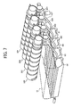
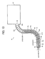
- a new and noble powder conveyance device includes a powder container section that contains powder, a powder conveyance pipe that guides downstream the powder mixed with air from the powder container section, and a powder conveyance member that conveys the powder installed in the powder conveyance pipe toward a conveyance destination.
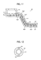
- the powder conveyance pipe includes a first conveyance section having a supply inlet and communicating with the powder container section. The first conveyance section receives the powder from the powder container through the supply inlet.
- a second conveyance section is provided in the powder conveyance pipe to communicate downstream with the first conveyance section via a first bending section.
- the second conveyance section downwardly extends to the conveyance destination being inclined from a horizontal at a larger angle than the first conveyance section.
- a third conveyance section is also provided in the powder conveyance pipe to communicate downstream with the second conveyance section via a second bending section.
- the third conveyance section extends toward the conveyance destination being inclined from the horizontal at a smaller angle than the second conveyance section.
- the third conveyance section has a replenishment outlet for replenishing the powder from the powder conveyance pipe to the powder conveyance destination.
- a space restriction member is provided in the powder conveyance pipe and is at least arranged in the second conveyance section to partially close an inner space of the second conveyance section.
- a powder passage restriction section is arranged in the first conveyance section to restrict passage of the powder.
- the printer 100 includes four process cartridges, which create toner images of yellow, magenta, cyan, and black (hereinafter referred to as Y, M, C, and K), respectively. Although these use Y to K different toner as image formation substance from each other, they have the same configuration and are replaced with new ones when arriving at their lives.
- the process cartridge 6Y includes a drum shaped photoconductive member 1Y, a drum cleaning device 2Y, a charge removing device (not shown), a charging device 4Y, and a developing device 5Y, and the like.
- the process cartridge 6Y is detachable to a printer body 100, whereby consumption parts can be replaced at once.
- each of the four process cartridges 6Y to 6K includes the photoconductive member 1, the drum-cleaning device 2, the discharge device (not shown), the charge device, and the developing device 5.
- the photoconductive member 1, the drum cleaning device 2, the discharge device (not shown), the charge device, and the developing device 5 are integrated and detached to the printer body.
- each of these, such as the photoconductive member 1, etc. is separately detached as consumption parts and is replaced upon need.
- usability of each is inferior.
- an image forming apparatus includes a process cartridge, to which a toner container storing toner to be supplied to a developing device included in a process cartridge is detached.
- a process cartridge to which a toner container storing toner to be supplied to a developing device included in a process cartridge is detached.
- the process cartridge need be detached from the image forming apparatus body.
- usability of a toner container is defective.
- the charge device 4Y is rotated by a driving device, not shown, clockwise in the drawing and uniformly charge the surface of the photoconductive member 1Y.
- the surface of the photoconductive member 1Y with the uniform charge is subjected to exposure scanning of a laser light L, whereby carrying a latent image for Y use.
- the latent image of Y use is developed to a Y toner image by the developing device 5Y using T toner.
- the Y toner image is transferred onto an intermediate transfer belt 8.
- a drum cleaning device 2Y removes toner remaining on the surface of the photoconductive member 1Y after the intermediate transfer process.
- the charge-removing device removes electrode remaining on the photoconductive member 1Y after the cleaning. Due to the charge removal, the surface of the photoconductive member 1Y is initialized and becomes ready for the next image formation.
- M to K toner images are similarly formed on the photoconductive members 1M to 1K in the other process cartridges 6M to 6K, and are subjected to intermediate transfer onto the intermediate transfer belt 8.
- an exposure device 7 is arranged below the process cartridges 6Y to 6K as a latent image formation device.
- the exposure device 7 executes exposure by emitting a laser light L in accordance with image information to photoconductive members 1 included in the process cartridges 6Y to 6K, respectively. By this exposure, latent images are formed on the photoconductive members 1Y to 1K, respectively.
- the above-mentioned exposure device 7 defuses and emits the laser light L created by a light source with a polygon mirror driven by a motor onto the photoconductive members 1 via plural optical lenses and mirrors.
- a sheet-feeding device including a sheet container cassette 26, a sheet-feeding roller 27, and a pair of rollers 28 installed in the sheet container cassette 26 are arranged.
- the sheet container cassette 26 includes plural transfer sheets P being piled as a printing member.
- the sheet-feeding roller 27 contacts the topmost transfer sheet P.
- the pair of registration roller 28 rotates and immediately stops rotating while sandwiching the transfer sheet P therebetween. Then, the pair of registration rollers launches the transfer sheet P toward a later mentioned secondary transfer nip at an appropriate time.
- the sheet feeding device serves as a conveyance device by combining the sheet feeding roller 27, and the pair of registration rollers 28 serving as a pair of timing rollers.
- the conveyance device conveys the transfer sheet P from the sheet container cassette 26 to the secondary transfer nip.
- an intermediate transfer unit 15 including an intermediate transfer belt 8 suspended and endlessly driven is arranged above the process cartridges 6Y to 6K.
- the intermediate transfer unit 15 aslo includes four primary transfer bias rollers 9Y to 9K, a cleaning device 10, a secondary transfer backup roller 12, a cleaning backup roller 13, a tension roller 14 and the like.
- the intermediate transfer belt 8 is suspended by these three rollers and is endlessly driven counter clockwise by one of them.
- These primary transfer bias rollers 9Y to 9K sandwiches the intermediate transfer belt 8 with the photoconductive members 1Y to 1K and form primary transfer nips there between, respectively.
- These primary transfer bias rollers 9Y to 9K apply a transfer bias having an opposite polarity (e.g. positive) to that of toner to the rear side surface of the intermediate transfer belt 8. All of rollers other than the primary transfer bias rollers 9Y to 9K are grounded.
- the intermediate transfer belt 8 receives primary transfer in which Y to K toner images formed on the photoconductive members 1Y to 1K are superimposed in turn when passing through the primary transfer nips for Y to K uses as endlessly travels. Thus, four-color superimposing toner images are formed on the intermediate transfer belt 8 as a four-color toner image.
- the secondary backup roller 12 sandwiches the intermediate transfer belt 8 with the secondary transfer roller 19 and create a secondary transfer nip.
- the four-color toner image on the intermediate transfer belt 8 is transferred onto a transfer sheet P at the secondary transfer nip. Some toner not transferred onto the transfer sheet P remains on the intermediate transfer belt 8 after passing through the secondary transfer nip, and is removed by a clean device 10.
- the transfer sheet P is sandwiched by the intermediate transfer belt 8 and secondary transfer roller 19, surfaces of which are moving in the same direction, and is conveyed in the direction opposite to the side of the pair of registration rollers 28.
- the four color toner image transferred onto transfer sheet P launched from the secondary transfer nip is fixed onto the surface thereof by heat and pressure when passing through the rollers of the fixing device 20.
- the transfer sheet P is ejected outside via a pair of sheet ejection rollers 29.
- a stack section 30 is arranged on the upper surface of the printer body. The transfer sheet P ejected outside by the pair of sheet ejection rollers 29 are stacked one by one on the stack section 30.
- the developing device 5Y includes a magnetic field generating device. Specifically, as shown, the developing device 5Y includes a developing sleeve 51Y carrying and conveying two-component developer having magnetic particle and toner on its surface as a developer carrier member. Also included is a doctor 52Y to smooth the developer carrier on the developing sleeve 51Y in a prescribed thickness as a developer restriction member. On the upstream side of the developer conveyance direction of the doctor 52Y, a developer container section 53Y is arranged to contain the developer not conveyed to a developing region opposing the photoconductive member 1Y and having been smoothed. Further, neighboring to the developer container section 53Y, a developer container section 54Y containing developer and two developer conveyance screws 55Y for stirring and conveying the developer are provided.
- a development layer is formed on the developing sleeve 51Y in the developing device 5Y.
- Toner is taken in to developer from the developer container 53Y due to movement of the development layer conveyed by rotation of the developing sleeve 51Y. Such taking in of the toner is executed to control toner density to fall within a prescribed range.
- the toner taken in the developer is charged by friction with carrier.
- the developer with the charged toner is supplied and carried on the surface of the developing sleeve 51Y installing a magnetic pole by magnetic force.
- the developer layer carried on the developing sleeve 51Y is conveyed in a direction shown by an arrow as the developing sleeve 51 Y rotates.
- the developer is carried to the developing region opposing the photoconductive member 1 Y.
- the latent image on the photoconductive member 1Y is developed.
- the developer layer remaining on the developing sleeve 51Y is conveyed toward the upstream section in the developer conveyance direction of the developer container section 53 Y as the developing sleeve 51Y rotates.
- a bottle container 31 is arranged between the intermediate transfer unit 15 and the stack section 30 arranged above the intermediate transfer unit 15.
- the bottle container 31 includes toner bottles 32Y to 32K storing Y to K toner, respectively.
- the toner bottles 32Y to 32K are arranged on the bottle containers 31 of respective toner colors from above.
- the Y to K toner in the toner bottles 32Y to 32K are replenished appropriately to the developing devices in the process cartridges 6Y to 6K, respectively, by a toner conveyance device as mentioned later in detail.
- These toner bottles 32Y to 32K are detachable to the printer body 100 in dependent from the process cartridges 6Y to 6K, respectively.
- the toner bottle 32Y is described with reference to FIG. 4 more in detail.
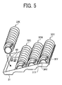
- the toner bottle 32K is mounted on the bottle container 31 as shown in FIG. 5 .
- a plastic case 34Y is provided on the leading section of the bottle body 33Y of the toner bottle 32Y
- the plastic case 34Y integrally includes a handle 35Y.
- a gear 37Y is provided on the side of the plastic case 34Y of the bottle body 33Y to integrally rotate with the bottle body 33Y.
- the plastic case 34Y integral with the handle 35Y is rotated, and the shutter 36Y moves in a circumferential direction of the plastic case 34Y and is open there, whereby a toner ejection outlet, not shown, is open.
- the plastic case 34Y is connected and secured to the bottle container 31.
- the handle 35Y is reversely rotated, and the plastic case 34Y is then disengaged with the bottle container 31. Then, a shutter 36Y is closed and the toner ejection outlet is closed. As a result, the toner bottle 32Y can be detached from the body of the printer 100 grasping the handle 35Y.
- the toner bottle 32Y can be mounted and detached from above the body of the printer 100, the manner of replacement of the toner bottle 32Y can be readily understandable and is simple. Further, since the handle 35Y is formed on the plastic case 34Y, the securing to the bottle container 31 can be easily performer by rotating the plastic case 34Y When the toner bottle 32Y is detached from the body of the printer 100, the shutter 36Y does not open even when the handle 35Y is rotated. Thus, the shutter 36Y is avoided from being erroneously open during replacement of the toner bottle 32Y suppressing toner leakage.
- the toner conveying device 40 is described with reference to FIGS. 6 and 7 , where toner bottles 32Y to 32K and the toner conveying devices 40Y to 40K are illustrated.
- the toner bottles 32Y to 32K, the intermediate transfer unit 15, and toner conveying devices 40Y to 40K are viewed at a different angle as illustrated in FIG. 7 .
- These toner conveying devices 40Y to 40K are arranged beside the intermediate transfer unit 15 in the body of the printer 100.
- a toner conveying device can be omitted from the process cartridges 6Y to 6K or the toner bottles 32Y to 32K, these devices can be more compact than conventional one.
- a conventional process cartridge is arranged adjacent to a toner bottle, there was designing restriction. However, they can separately be arranged according to this embodiment. Thus, a freedom degree of designing can be improved and the printer can be compact.
- Ejections outlets of the toner bottles 32Y to 32K, the toner conveying devices 40Y to 40K, and the toner replenishment inlets of the developer container sections 54Y to 54K of the developing devices 5Y to 5K are arranged on one side of the intermediate transfer unit 15.
- a toner conveyance path of the toner conveying devices 40Y to 40K can be minimized, and the printer can be compact while suppressing toner clogging during toner conveyance.
- the toner conveying device 40Y for Y toner conveyance use is typically described with reference to FIG. 6 .
- the toner conveying device 40Y mainly includes a driving motor 41Y, a driving gear 42Y, and a toner conveyance pipe 43Y. Inside the toner conveyance pipe 43Y, a plastic coil, not shown, is arranged.
- the driving gear 42Y meshes with a gear 37Y of the toner bottle 32Y, and is integrally rotated with the gear 37 of the toner bottle 32Y whereby the bottle body 33 Y is rotated when the driving motor 41Y is driven. Then, when the density detection sensor 56Y of the developing device 5Y of FIG.
- the toner in the bottle body 33Y drops through an ejection outlet, not shown, of the plastic case 34Y to a toner reception section, not shown, of the toner conveying device 40Y
- the toner reception section communicates with the toner conveyance pipe 43Y, and accordingly, a coil, not shown, installed in the toner conveyance pipe 43Y is simultaneously rotated when the driving motor 41Y is driven and the bottle body 33Y is rotated. Due to the rotation of the coil, the toner dropped on the toner receiving section is conveyed through the toner conveyance pipe 43Y and replenished to a toner replenishment inlet, not shown, of the developer container 54Y. In this way, toner density in the developing device 5Y is adjusted.
- an optical sensor or a CCD camera or the like can be employed to count a number of pixels of a reference image formed on the photoconductive member 1Y, and toner replenishment can be executed based on the calculation.
- the toner conveying device 40Y for Y use as a powder conveyance device is described more in detail with reference to FIG. 8 .
- a conveyance coil 70Y serving as a powder conveyance use member is arranged contacting the inner wall of the toner conveyance pipe 43Y serving as a powder conveyance pipe 43Y
- a gap between the toner conveyance pipe 43Y and the conveyance coil 70Y is sets to from about 0.1 to about 0.2mm.
- the conveyance coil 70Y can rotate even though the toner conveyance pipe 43Y is bent. Since the toner conveyance pipe 43Y is not necessarily formed straight, a designing freedom increases, and the developing device can be compact.
- a conveyance device includes a screw having a shaft or the like instead of the conveyance coil 70Y
- toner can be conveyed in a non-liner conveyance path in a certain situation.
- the shaft inclusion conveyance device with the conveyance use coil
- the latter can readily be bent.
- a resisting force against deformation which is caused by rotation at a curvature section of the toner conveyance pipe 43Y, is smaller than when the conveyance use coil is used.
- the conveyance coil 70Y can more decrease a slide contact load applied from the toner conveyance pipe 43Y than the shaft inclusion conveyance device.
- a space restriction member 60y is arranged at a slant section 43cY (e.g. a mostly slanting section in the toner conveyance pipe 43Y) within a hollow section of the conveyance coil 70Y.
- the outer diameter of the space restriction member 60Y is slightly smaller than the internal diameter of the conveyance coil 70Y, so that a resistance is not created during slide contacting thereto while highly restricting passage of toner.
- the internal diameter of the conveyance coil 70Y is about 5mm with tolerance of from 0 to +0,05.
- the outer diameter of the space restriction member 60Y is about 4.5mm with tolerance ⁇ 0.05.
- the space restriction member 60Y is held by a conveyance coil 70Y to rotate together with the conveyance coil 70Y.
- the space restriction member 60Y can be made of an elastic member, such as sponge, etc., and is held tightly contacting the inner side of the conveyance coil 70Y.
- the higher the rate of space restriction by the space restriction member 60Y at the slant section 43cY in the toner conveyance pipe 43Y the higher the effectiveness.
- the inventors have confirmed through their experiment that the above-mentioned phenomena can be suppressed without completely evacuating the air by 100% from the slant section 43cY of the toner conveyance pipe 43Y.
- the problem of the flowing in can be suppressed.
- about 50% of the space of the slant section 43cY is occupied by the space restriction member 60Y.
- the toner accumulates at the space of the slant section 43cY usually almost occupied by air compresses, by its weight, the toner existing at the downstream of the toner conveyance pipe 43Y.
- the space restriction member 60Y restricting the pipe inner space at the slant section 43cY with the space restriction member 60Y, the compression force can be decreased.
- a passage restriction section 105Y is provided at an upstream side horizontal section 43a in the toner conveyance pipe 43Y to effectively restrict passage of the toner.
- Replenishment of the toner from the toner bottle 32Y to the toner conveying device 40Y via a toner ejection outlet, not shown, is executed per rotation of the toner bottle 32Y. Since toner replenishment is executed per rotation, an amount of toner replenished at once exceeds that conveyed by the conveyance coil 70Y. The excessive toner flows through a center space of the conveyance coil 70Y and reaches the developing device 5Y regardless of the rotation of the conveyance coil 70Y. Thus, a lot of toner is supplied to the developing device 5Y per rotation of the toner bottle, and density of toner in the developing device 5Y sharply increases and possibly causes a problem, such as background stein, etc.
- the passage restriction section 105Y has a high performance of restricting an amount of toner passing through the toner conveyance pipe 43Y
- a rotational shaft 71Y is internally adhered to the conveyance coil 70Y.
- more than one winding of the conveyance coil 70Y is provided in the region A as shown in FIG. 10 .
- the conveyance coil 70Y contacts the inside of the toner conveyance pipe 43Y and the rotational shaft 71Y contacts the inside of the conveyance coil 70Y while more than one winding of the conveyance coil 70Y is provided in the region A, almost no gap exists and the toner can hardly pass through by its own weight.
- the flow of the toner is stopped at the region A, and passes only by rotation of the conveyance coil 70Y.
- a diameter of the rotation shaft 71Y is smaller in the region B downstream of the region A than that of the region A.
- the leading end of the rotational shaft 71Y extends from the upstream side horizontal section 43aY to almost an inlet where the upstream side curvature section 43bY starts bending.
- the passage restriction section 105Y is formed from the rotational shaft 71 Y and the conveyance coil 70Y.
- the leading end of the downstream side of the rotational shaft 71Y likely interferes with an inner wall of the toner conveyance pipe 43 Y in the vicinity of the inlet, the rotational shaft 71Y and the toner conveyance pipe 43Y or the like can be damaged.
- the leading end of the downstream side of the rotational shaft 71Y can avoid interfering with the inner wall of the toner conveyance pipe 43Y in the vicinity of the inlet, while suppressing the damage of the rotational shaft 71Y and the toner conveyance pipe 43Y or the like.
- the toner passage restriction performance exerted by the rotational shaft 71Y and the conveyance coil 70Y somewhat decreases indeed in the region B.
- the leading end of the rotational shaft 71 extends up to the region B, the toner conveyance path of the toner conveyance pipe 43Y is narrowed in the region B, toner passage is restricted in proportion to an amount of narrowing.
- the space restriction member 60Y is arranged at the slant section 43cY in this exemplary configuration as in the first exemplary configuration, an amount of air is decreased by the space restriction member 60Y at the slant section 43cY.
- excessive blending of the toner with the air, and accordingly, excessive increase of toner fluidity can be suppressed.
- the toner conveyance pipe 43 only includes a small amount of air at the slant section 43cY, the toner is more likely prevents from being excessively blended with the air while fluidity prevents from being excessively increased.
- the toner is more hardly flown into the developing device 5Y.
- a prescribed amount of the toner is more precisely replenished to the developing device 5Y.
- the space restriction member 61Y is arranged extending up to the downstream side horizontal section 43eY of the toner conveyance pipe 43Y via the downstream side curvature section 43dY in addition to the slant section 43cY. Further, the space restriction member 61 Y integrally extends from the slant section 43cY to the downstream side horizontal section 43eY.
- a cubic capacity (an air capacity) other than a space needed for toner conveyance within the toner conveyance pipe 43Y can be decreased.
- the toner is not excessively blended with the air, and excessive increase of the fluidity of the toner can be suppressed in the toner conveyance pipe 43Y.
- the space restriction member 61Y is preferably arranged as long as possible starting from the downstream side horizontal section 43eY to the upstream side of the slant section 43cY.
- a rate of the space restriction member 61 Y is preferably 90% of a cross section of the toner conveyance pipe as formed by the internal diameter of the conveyance coil 70Y (i.e., an area drawn by a dotted circular line in the drawing) as shown in FIG. 12 .
- High fluidity toner is used to achieve high-speed toner conveyance.
- an acceleration coagulation degree representing an index of fluidity of the toner is not more than 40%.
- a measurement manner of an acceleration coagulation degree is described below.
- Powder Tester manufactured by Hosokawa Micron is used.
- a sample as a measurement objective is left as is in a constant-temperature oven (35 ⁇ 2 degree centigrade, 24 ⁇ 1(h)).
- three types of a minus sieve each having a different mesh are used.
- An coagulation degree is obtained by calculating an amount of toner remaining after using the sieve based on the following calculations: Weight of toner remaining on minus sieve of upper step / Amount of extracted sample ⁇ 100 ; Weight of toner remaining on minus sieve of middle step / Amount of extracted sample ⁇ 100 ⁇ 3 / 5 ; and Weight of toner remaining on minus sieve of lower step / Amount of extracted sample ⁇ 100 ⁇ 1 / 5.
- a heating coagulation degree % is obtained by totaling the above listed three calculation values.
- the accelerated coagulation degree of the toner represents an index obtained by piling up three types of meshes in an order of a size thereof (texture) and placing particles on the uppermost step while sieving at a prescribed vibration, and then calculating weights of the toner on the meshes, respectively.
- toner of fine fluidity of an accelerated coagulation degree of not more than 40% is used in a conventional toner conveying device as mentioned above with reference to the Japanese Patent Application Laid Open No. 2005-24665 , in which flowing of toner from the toner conveying device into the developing device is suppressed, the inside of the toner conveyance pipe 43Y is almost occupied by air. Accordingly, the toner is excessively blended with the air in the toner conveyance pipe 43Y, and the fluidity of the toner excessively increases, and accordingly, the toner is excessively conveyed to the downstream of the toner conveyance pipe 43Y per second. As a result, a lot of developer unavoidably flows into the developing device side, needlessly.
- the space restriction member 60Y and 61Y are arranged in the toner conveyance pipe 43Y and decrease an amount of the air in the toner conveyance pipe 43Y, whereby suppressing excessive blending of the toner with the air.
- the toner having an accelerated coagulation degree of not more than 40% is used, excessive increase of fluidity of the toner is suppressed in the toner conveyance pipe 43Y, and accordingly, the above-mentioned toner flowing can be suppressed.
- toner having an average round shape degree not less than 0,90 e.g. from about 0, 90 to about 1,00 is employed.
- the round shape degree represents an index of a degree of unevenness of a toner particle, and is 1,00 when the toner is perfectly a sphere, and is smaller in portion to complexity of a surface shape.
- Round shape degree Length of circumference having the same area as projected area of particle / Length of circumference of projected image of particle
- a transfer performance is excellent.
- the toner particle does not include a corner, a stirring torque caused by developer in the developing device 5 is small, and an abnormal image is scarcely outputted due to stable drive of stirring.
- the toner particle Since the toner particle is not angulous, a grinding force by the toner particle itself is small. Thus, the toner neither damages nor wears the surface of the photoconductive member and the charging member.
- the round shape degree can be measured by a flow system particle image analysis device FPTA-1000 manufactured by TOA Medical Electronics Co., Ltd.
- measurement is executed as follows: An amount of 0, 1 to 5 ml of interfacial active agent, preferably alkyl benzene sulfonate (ABS), is previously added to an amount of I00 to 150ml of water stored in a container as a dispersant from which impurity solid substance is removed. Further, amount of about 0, 1 to about 0, 5g of sample is added thereto. Suspension with the dispersed sample is then subjected to a dispersion process in an ultrasonic dispersion device for one to three minutes. The shape and granularity of the toner is measured by the above-mentioned device on condition that a dispersion liquid density is from 3000 to 10000 (pieces/micro liter).
- interfacial active agent preferably alkyl benzene sulfonate (ABS)
- the weight average particle diameter (D4) of toner is preferably from three to eight micrometer. In this range, a dot reproduction performance is excellent, because the toner particle has a sufficiently small diameter in relation to a fine latent image dot.
- D4 is not more than 3micrometer, transfer efficiency and a blade cleaning performance or the like likely decrease.
- a ratio D4/D1 between a weight average particle diameter (D4) and a number average particle diameter (D1) is preferably from 1,00 to 1,40. In proportion to a vicinity level of the ratio to 1,00, a particle diameter distribution is sharp. With such a small particle diameter toner, a charge amount distribution of the toner becomes uniform, and a high quality image excluding background stein can be obtained. Further, the transfer efficiency can be improved in an electrostatic transfer system.
- a Coulter counter TA- ⁇ As a measurement device measuring granularity distribution of a toner particle using the Coulter counter method, a Coulter counter TA- ⁇ , and a Coulter multi counter TA-II, a Multisizer- ⁇ (each manufactured by Coulter Co, Ltd.) are exemplified.
- an amount of 0, 1 to 5(ml) of the interfacial active agent preferably alkyl benzene sulfonate (ABS)
- ABS alkyl benzene sulfonate
- the ISOTON- ⁇ manufactured by Coulter Co, Ltd.
- the measurement device measures a weight and a number of pieces of toner particles using an aperture having a size of about 100mierometer and calculates weight and number of distributions. Based on the distribution obtained, the values D4 and D1 can be calculated.
- the toner used in this embodiment is called a polymerization toner, which is obtained by closs-linlcing and/or causing extension reaction of toner material liquid, which is produced at least by dispersing polyester pre-polymer, polyester, colorant, and mold release having a functional group including nitrogen atom into organic solvent.
- a polymerization toner which is obtained by closs-linlcing and/or causing extension reaction of toner material liquid, which is produced at least by dispersing polyester pre-polymer, polyester, colorant, and mold release having a functional group including nitrogen atom into organic solvent.
- Exemplary component material of toner and a manufacturing method thereof are described herein below.
- Polyester is obtained from polycondensation reaction between multivalent alcohol chemical compound and multivalent carboxylic acid chemical compound.
- multivalent alcohol chemical compound PO
- divalent alcohol DIO
- trivalent alcohol TO
- Amalgam with only DIO or DIO and a small amount of TO is preferable.
- alkyleneglycol such as ethylene glycol, 1,2-propylene glycol, 1,3-propylene glycol, 1,4-butanediol, hexanediol, etc.
- alkylene-ether-glycol such as diethylene glycol, triethylene glycol, dipropylene glycol, polyethylene glycols, polypropylene glycol, polytetra-methylene- ether-glycol, alicyclic-diol, such as 1, 4-cyclohexane-dimethanol, hydrogenised-bisphenolA, etc.
- bisphenol class such as bisphenol A, bisphenol F, bisphenol S, alicyclic-diol with additament of alkylene-oxide, such as ethylene oxide, propylene oxide, butylenes oxide, and Bisphenol class with additament of alkylene-oxide, such as ethylene oxide, propylene oxide, butylenes oxide, etc.
- alkyleneglycol having the carbon number of 2 to 12 and the bisphenol class with additament of alkylene-oxide are preferable used. Simultaneous usage of these is more useful.
- multivalent fatty series alcohol such as glycerine, trimethylolethane, trimethylolpropane, pentaerythritol, sorbitol, and more than trivalent phenol class, such as tris phenol PA, phenol novolac, cresol novolac, and the more than trivalent phenol class with additament of alkylene-oxide, etc., are preferably used.
- the multivalent carboxylic acid (PC) divalent carboxylic acid (DIC) and more than trivalent carboxylic acid (TC) are exemplified, and the DIC alone and the mixture thereof and the small amount of TC are preferably used.
- DIC divalent carboxylic acid
- Alkylene dicarboxylic acid such as succinate, adipic acid, sebacic acid
- Alkenylene dicarboxylic acid such as maleic acid, fumarate acid
- aromatic series dicarboxylic acid such as phthalic acid, isophthalic acid, terephthalic acid, naphthalenedisulfonic dicarboxylic acid, etc.
- Alkenylene dicarboxylic acid having a carbon number of from 4 to 20 and aromatic series dicarboxylic acid having a carbon number of from 8 to 20 are preferably used.
- aromatic series multivalent carboxylic acid having a carbon number of from 9 to 20, such as trimellitic acid, pyromellitic acid, etc. are exemplified.
- acid anhydride of the above-mentioned material or low alkyl ester, such as methyl ester, ethyl ester, isopropyl ester, etc. can be reacted with multivalent alcohol (PO).
- a ratio between the multivalent alcohol (PO) and the multivalent carboxylic acid is as follows:
- An equivalent ratio OH/COOH between a hydroxyl group OH and a carboxyl group is usually 2/1 to 1/1, preferably, 1,5/1 to 1/1, more preferably, 1,3/1 to 1,02/1.
- a polycondensation reaction of the PO and the PC is executed as follows: With the presence of known esterification catalyst, such as tetrabutyltitanate, diButyltin oxide, etc., these are heated up to about 150 to 280 degree centigrade, and produced water is evaporated while reducing the pressure upon need, thereby polyester having hydroxyl group is obtained.
- the hydroxyl group of the polyester is preferably more than five, and acid number of the polyester is generally from 1 to 30, preferably from 5 to 20. Due to the acid number, a charge performance tends to be negative and affinity between the printer sheet and toner is fine while a low temperature fixing performance is improved when a fixing process is executed onto a printing sheet. However, when the acid number exceeds 30, charge stability tends to deteriorate in response to a change of environment. Further, weight-average molecular weight ranges from 10 to 400 thousand, preferably, 20 to 200 thousands. When weight-average molecular weight is less then 10 thousands, offset resistance performance deteriorates. When 400 thousand is exceeded, the low temperature fixing performance deteriorates.
- Polyester preferably includes not modified Polyester obtained by the above-mentioned polycondensation reaction, and Urea modified Polyester.
- Urea modified Polyester carboxyl group of the tail end of the Polyester obtained by the above-mentioned polycondensation reaction and hydroxyl group or the like are reacted with the multivalent isocyanate chemical compound (PIC), thereby Polyester prepolymer (A) having the isocyanate group is produced.
- PIC multivalent isocyanate chemical compound
- fatty series multivalent isocyanate such as tetramethylene di-isocyanate, hexamethylene diisocyanate, 2,6-di-isocyanate methylcaproate, alicyclic polyisocyanate, such as Isophorone Diisocyanate, cyclohexyl methane di-isocyanate, aromatic series di-isocyanate, such as Tolylene diisocyanate, diphenylmethane diisocyanate, aromatic fatty series di-isocyanate, such as ⁇ , ⁇ , ⁇ ' , ⁇ '-tetramethylenexylylene di-isocyanate, Isocyanate class, such as polyisocyanate blocked by phenol derivatives, oxime, caprolactam, or the like, and simultaneous use of at least two of the above mentioned material are exemplified.
- Isocyanate class such as polyisocyanate blocked by phenol derivatives, oxime, caprolactam,
- a ratio of the multivalent isocyanate chemical compound is as follows:
- An equivalent ratio NCO/OH between an isocyanate group NCO and a polyester hydroxyl group OH having a hydroxyl group is generally 5/1 to 1/1, preferably, 4/1 to 1, 2/1, more preferably, 2,5/1 to 1,5/1.
- NCO/OH exceeds 5
- a low temperature fixing performance deteriorates.
- urea content decreases, and unti hot offset performance deteriorates.
- the content of a component of the (PIC) included in the polyesterprepolymer (A) having the isocyanate group is usually 0, 5 to 40 weight%, preferably 1 to 30 weight%, and more preferably 2 to 20 weight%.
- the content is less than 0, 5 weight%, both of the heat resistance storage stability and low temperature fixing performances are hardly satisfied and hot offset resistance performance deteriorates.
- 40 weight% is exceeded, the low temperature fixing performance deteriorates.
- polyesterprepolymer (A) having the isocyanate group per molecule Ordinarily, more than one, preferably 1, 5 to 3, more preferably 1, 8 to 2, 5 items of the isocyanate group are included in the polyesterprepolymer (A) having the isocyanate group per molecule.
- a molar weight of the Urea modified Polyester decreases, and accordingly, the hot offset resistance performance deteriorates.
- Divalent amine chemical compound B1 more than trivalent amine chemical compound B2, amino alcohol B3, amine mercaptan B4, amine acid B5, and the material (B6) obtained by blocking amine groups of amino group B1 to B5 are exemplified.
- aromatic diamine such as phenylenediamine, diethyltoluenediamine, 4,4'-diamino diphenylmethane
- alicyclic diamine such as 4,4'-diamino, 3,3'-dimethyl dicyclo hexyl methane, diamine cyclohexane
- Isophorone Diamine aliphatic diamine, such as ethylene diamine, tetramethylendiamine, hexamethylene diamine, etc.
- diethylenetriamine, triethylenetetramine, etc. are exemplified.
- amino alcohol B3 ethanolamine, hydroxyethyl aniline, etc.
- amino-mercaptan B4 amino-ethyle mercaptan, amino-propyl mercaptan, etc., are exemplified.
- amino acid B5 amino propional acid, aminocaproic acid, etc.
- material (B6) blocking the amino group ketimine chemical compound, oxazolidine chemical compound obtained from the amino groups of the above-mentioned B1 to B5 and ketone class, such as acetone, methyl ethyl ketone, methyl isobutyl ketone, etc.
- ketimine chemical compound, oxazolidine chemical compound obtained from the amino groups of the above-mentioned B1 to B5 and ketone class such as acetone, methyl ethyl ketone, methyl isobutyl ketone, etc.
- the B1 and the mixture of the B1 and a small amount of the B2 are preferably used.
- the ratio of the amine class B is as follows: An equality ratio NCO/NHx between the isocyanate group NCO included in the polyesterprepolymer A having the isocyanate group and the amine group NHx included in the amine class is usually 1/2 to 2/1, preferably 1, 5/1 to 1/1, 5, further preferably 1,2/1 to 1/1,2.
- the urea-modified polyester can include urea combination and urethane combination.
- a mole ratio between the urea combination content and the urethane combination content is unusually 100/0 to 10/90, preferably 80/20 to 20/80, more preferably 60/40 to 30/70.
- the mole ratio of the urea combination is less than 10%, a hot offset resistance performance deteriorates.
- the urea modified polyester is produced using a one shot method or the like. With the presence of known esterification catalyst, such as tetrabutyltitanate, dibutyltin oxide, etc., the material PO and PC are heated up to about 150 to 280 degree centigrade, and water thus produced is evaporated while reducing the pressure upon need, thereby polyester having hydroxyl group is obtained. Then, at 40 to 140 degree centigrade, the multivalent isocyanate (PIC) is reacted therewith, and the polyester prepolymer (A) having the isocyanate group is obtained. Then, at 0 to 140 degree centigrade, the amine class B is reacted with the A and the urea modified polyester is obtained.
- esterification catalyst such as tetrabutyltitanate, dibutyltin oxide, etc.
- solvent can be used upon need.
- aromatic series solvent such as toluene, xylene, ketone class, such as acetone, methyl ethyl ketone, methyl isobutyl ketone, ester class, such as ethyl acetate, amide class, such as dimethylformamide, dimethylacetamide, and ether class, such as tetrahydrofuran, each chemically stable against the isocyanate (PIC), are exemplified.
- aromatic series solvent such as toluene, xylene
- ketone class such as acetone, methyl ethyl ketone, methyl isobutyl ketone
- ester class such as ethyl acetate
- amide class such as dimethylformamide, dimethylacetamide
- ether class such as tetrahydrofuran
- reaction stopping agent is used upon need and a mole weigh of urea modified polyester obtained can be adjusted.
- monoamine such as diethylamine, dibutylamine, butyl amine, lauryl amine, and material obtained by blocking these, such as ketimine chemical compound, etc., are exemplifed.
- the weight average molar weight of the urea modified polyester is generally more than ten thousand, preferably, 20 thousand to 10 million, more preferably, 30 thousand to 10 million. When less than 10 thousand, the hot offset resistance performance deteriorates.
- Various number average molar weights of the urea-modified polyester can be used as far as it is readily obtained to calculate the weight average molar weight especially when not modified polyester is used.
- the number average molar weight is generally from 2000 to 1500, preferably 2000 to 10000, more preferably 2000 to 8000. When 20000 is exceeded, the low temperature performance and brilliance performance deteriorate when used in a full color system.
- the not modified polyester can include polyester modified by chemical combination other than the urea combination.
- the not modified polyester and the urea-modified polyester are preferably at least partially miscible with each other in view of the low temperature fixing performance and hot offset resistance performance. Accordingly, the not modified polyester and the urea-modified polyester preferably have similar composition to each other.
- the weight ratio between the not modified polyester and the urea-modified polyester is usually from 20/80 to 95/5, preferably 70/30 to 95/5, and more preferably 75/25 to 95/5, yet more preferably 80/20 to 93/7.
- weight ratio is less than 5%, both of the heat resistance storage stability and low temperature fixing performances are hardly simultaneously satisfied while hot offset resistance performance deteriorates.
- a glass transition point (Tg) of binder resin including the not modified polyester and the urea-modified polyester is generally from 45 to 65 degree centigrade, preferably from 45 to 60 degree centigrade. When 45 deg centigrade is not exceeded, the heat resistance deteriorates. When 65 degree centigrade is exceeded, the low temperature fixing performance is insufficient.
- the urea modified polyester is readily able to stay on the surface of the obtained toner parent particle, the urea modified polyester can show fine heat resistance even having the low glass transition point.
- colorant all of known dye and pigment can be used, such as carbon black,nigrosine dye, iron black, naphthol yellow S,hansa yellow (10G, 5G, G), cadmium yellow, yellow ferric oxide, yellow ocher, chrome yellow, titanium yellow, polyazo yellow, oil yellow, hansa yellow (GR, A, RN, R), pigment yellow L, benzidine yellow (G, GR), permanent yellow (NCG),vulcanfast Yellow (5G, R), tartrazin lake, quinoline yellow lake, anthracene yellow BGL, isoindoline Yellow,colcothar,red lead oxide,lead vermillion,cadmium red, cadmium Mercury-Red,stibium red,permanent red 4R,Para Red,fire red,parachlororthonitroaniline red, Lithol fast Scarlet G,Brilliant fast Scarlet, Brilliant Carmine BS ,permanent red (F2R,F4R,FRL,FRLL,F4RH),fast Scar
- the colorant can also be used as a master patch combined with resin.
- binder resin producing the master patch or being stirred and blended with the master patch styrene, such aspolystyrene, poly-p-chlorostyrene, polyvinyl toluene, and its polymer of derivative substitution of the styrene, or copolymer of vinyl compound and those materials, polymethyl methacrylate, polybutyl methacrylate polyvinyl chloride, polyvinyl acetate, polyethylene resin, polypropylene, polyester, epoxide resin, polyol polyol resin, polyurethane, polyamide, polyvinyl butyral, polyacrylic acid resin, rosin, modified rosin, terpene resin, fatty series or alicyclic molecule carbon hydrid resin, aromatic series petroleum resin, chlorinated paraffin, paraffin wax are exemplified. These can either be use alone or being blended.
- charge control agent known material can be used.
- nigrosine dye, triphenylmethane dye, chrome inclusion metal-complex compound dye, molybdic acid chelate pigment, rhodamine dye, alkoxy amine, fourth degree ammonium salt including fluorine modified fourth degree ammonium saltalkylamido, phosphor simple substance or chemical compound, tungsten simple substance or chemical compound, fluorine activation, salicylic acid metal salt, and salicylic acid derivatives metal salt can be used.
- An amount of usage of charge control agent is not limited to one, but is determined in accordance with a type of binder resin, presence or absence of additives used upon need, and a toner-manufacturing manner including a dispersion manner.
- the usage amount preferably ranges from 0, 1 to 10, more preferably, 0,2 to 5 weight part.
- 10-weight part is exceeded, a charge amount of toner is excessive, and accordingly, efficiency of the charge control agent deteriorates.
- electrostatic absorption force caused between the developing roller and the toner increases, and fluidity of the developer decreases, and further image density deteriorates.
- low melting point wax having a melting point at about from 50 to 120 degree centigrade is used more preferably effectively work between the fixing roller and the toner boundary face when dispersed into a binder resin.
- the low melting point wax is effective in view of the high temperature off set, because the fixing roller does not need a release agent such as oil, etc.
- the below described wax component can be employed.
- plant wax such as carnauba wax, cotton wax, wood wax, rice wax, etc.
- animal wax such as yellow beeswax, lanolin, etc.
- mineral wax such as ozokerite, serisin
- Petroleu wax such as paraffin, microcrystalline, petrolatum, etc.
- synthetic carbon hydride wax such as Fischer-Tropsch wax, polyethylene wax, etc.
- synthetic wax such as ester, ketone, ether, etc.
- fatty acid amide such as crystal giant molecule having a long alkyl group as a lateral chain, such as hydroxyl 12-stearic acid amide hydroxystearate, stearic acid amide, phthalic anhydride imide, chlorinated hydrocarbon, etc.
- homopolymer of polyacrylate such as copolymer of n- stearyl acrylate ethyle methacrylate, etc., serving as a tow-molecular weight crystalline giant molecule resin, or copolymer thereof, such as poly-n-stearyl methacrylate, poly-n-lauryl methacrylate, etc.
- poly-n-stearyl methacrylate poly-n-lauryl methacrylate, etc.
- the charge control agent and the mold release agent can be melt and blended together with master batch and binder resin, and can be added when melted and dispersed into organic solvent.
- a nonorganic fine particle is used to help support fluidity, developing performance, and charge performance of toner particle.
- a diameter of a primary particle of the nonorganic fine particle is preferably 5 x 10 -3 to 2micrometer, more preferably, 5 x 10 -3 to 0,5micrometer.
- a specific surface measured by the BET method is preferably 20 to 500(m 2 /g).
- a usage rate of this inorganic fine particle is 0,01 to 5 weight percent of toner.
- hydrophobic silica fine particle and hydrophobic titanium oxide fine particle are preferably used at the same time among those.
- the titanium oxide fine particle is excellent in environmental safety and image density stability. However, due to tendency of deterioration of charge rising performance, when the titanium oxide fine particle addition amount increases more than silica fine particle addition amount, this ill influence becomes serious.
- the additional amount of the hydrophobic silica fine particle and the hydrophobic titanium oxide fine particle is within 0,3 to 1,5-weight%, the charge rising performance does not largely deteriorate, and accordingly, a prescribed charge rising performance can be obtained. Thus, the stable image quality can be obtained during repeat copying.
- colorant, not modified polyester, polyester prepolymer having isocyanate group, and releasing agent are dispersed into organic solvent, thereby toner material liquid is produced.
- the organic solvent preferably has a volatile performance with a boiling point of less than 100 degree centigrade in view of ease of removal after formation of toner parent particle.
- aromatic series solvent such as toluene, xylene, etc.
- halogenated hydrocarbon such as dichloromethane, 1, 2-dichloroethane, chloroform, carbon tetrachloride, etc.
- a usage amount of the organic solvent is typically from zero to 300 weight part, preferably from zero to 100 weight part, more preferably from 25 to 70 weight part in relation to a polyester prepolymer 100 weight part.
- toner material liquid is subjected to emulsification in a drainage texture medium with the presence of interfacial active agent and resin fine particle.
- the drainage texture medium can include only water, or organic solvent such as alcohol (e.g. methanol, isopropyl alcohol, ethylene glycol), dimethylformamide, tetrahydrofuran, cellusolve class (e.g. methyl cellusolve), low ketone (e.g. acetone, methyl ethyl ketone), etc.
- a usage amount of the drainage texture medium is typically from 50 to 2000 weight parts, preferably 100 to 1000 weight parts in relation to the toner material liquid 100-weight part. Specifically, in the case the 50-weight part is not exceeded, the toner material liquid is not preferably dispersed, and accordingly, a toner particle having a prescribed diameter cannot be obtained. In the case 20000-weight part is exceeded, it is wasteful.
- interfacial active agent such as alkyl benzene sulfonate, alfa-olefin sulfonate, phosphate ester, etc.
- amine salt type such as alkylamine salt, etc., aminoalcohol fatty acid derivatives, polyamineatty acid derivatives, imidazoline
- fourth ammonium salt type cation interfacial active agent such as alkyltrimethylammonium salt, dialkyl dimethyl ammonium salt, dialkyl dimethyl benzil ammonium salt, pyridinium salt, alkyl isoquinolinium salt, benzethonium chloride, etc.
- non-ion interfacial active agent such as fatty acid amide derivatives, multivalent alcohol derivatives, etc., and ampholyte interfacial active
- the interfacial active agent including fluoroalkyl group preferably used, fluoro alkylcarboxylic acid having carbon number from 2 to 10 and its metal salt, perfluoro octane sulfonyl glutamic acid disodium, 3-(ro-fluoroa1kyl (C6-C11) oxy)-1-alkyl (C3-C4) sulfonic natrium, 3-( ⁇ -fluoroalkanoyl (C6-C8))-N-ethylamino)-1-propane sulfonic natrium, fluoroalkyl (C11-C20) carboxylic acid and its metal salt, perfluoroalkyl carboxylic acid (C7-C13) and its metal salt, perfluoroalkyl (C4-C12) sul
- SURFLON® S-111, S-112 and S-113 produced by Asahi Glass Co, Ltd., FLUORAD FC-93, FC-95, FC-98, and FC-129 (produced by Sumitomo 3M Co, Ltd.), UNIDAIN DS-101 and DS-102 (produced by Daikin Industrial Co, Ltd.), MEGAFACK F-110, F-120, F-113, F-191, F-812 and F-833 (produced by Dainihon Inki Co, Ltd.), EFTOP EF-102, 103, 104, 105, 112, 123A, 123B, 306A, 501, 201, 204 (produced by Tohchem products Co, Ltd.), and HUTARGENT F-100 and F150 (produced by NeOS Co, Ltd.) are exemplified.
- first and second fatty series having fluoroalkyl group, second amine acid, fourth fatty series ammonium salt such as perfluoroalkyl (C6-C10) sulfone amide propyltrimethylammonium salt, etc., benzal conium salt, benzethonium chloride, pyridinium salt, and imidazolium salt are exemplified.
- SURFLON® S-121 produced by Asahi Glass Co, Ltd, FLUORAD FC-135 produced by Sumitomo 3M Co, Ltd., UNIDAIN DS-202 produced by Daikin Industrial Co, Ltd., MEGAFACK F-150 and F-824 produced by Dainihon Inki Co, Ltd., EFTOP EF-132 produced by Tohchem products Co, Ltd., and HUTARGENT F-300 produced by NeOS Co, Ltd, are exemplified.
- a resin fine particle is added to stabilize a toner parent particle produced in a drainage texture.
- the resin fine particle is preferably added so that coverage thereof on the surface of the toner parent particle is from 10 to 90%.
- polymethacrylic acid methyle fine particle having a size of 1 micrometer or 3 micrometer polystyrene fine particle having a size of 0,5micrometer and 2micrometer, and poly (styrene-acrylonitrile) fine particle having a size of 1micrometer are exemplified.
- PB-200H (produced by Kao Co., Ltd), SGP (produced by Soken Chemical & Engineering Co., Ltd.), TECHNOPOLYMER SB (produced by Sekisui Plastics Co., Ltd.), SGP-3G (produced by Soken Chemical & Engineering Co., Ltd.), and MICRO PEARL (produced by Sekisui Fine Chemical Co., Ltd.) or the like are used.
- inorganic compound dispersant such as tricalcium phosphate, calcium carbonate, titanium oxide, colloidal silica, hydroxyapatite, etc., can be used.
- Droplet of dispersant can be stabilized by giant molecule protection chorioid and used together with the above-mentioned resin fine particle and the inorganic chemical compound dispersant.
- acidum class such as acrylic acidmathacrylic acid, ⁇ -cyanoacrylic acid, ⁇ -cyanomathacrylic acid,itaconic acid, crotonic acid,fumaric acid, maleic acidmaleic anhydride, etc.
- (meta)acrylic monomeric substance having hydroxyl such as acrylic acid- ⁇ -hydroxyethyl, mathacrylic acid- ⁇ -hydroxyethyl, acrylic aeid- ⁇ -hydroxypropyl, mathacrylic acid- ⁇ -hydroxypropyl, acrylic acid- ⁇ -hydroxypropyl, mathacrylic acid- ⁇ -hydroxypropyl,acrylic acid-3-chloro-2-hydroxypropyl, mathacrylic acid-3-chloro-2-hydroxypropyl, diethylene glycol monoacrylic acid ester, diethylene glycol monomathacrylic acid ester,
- a dispersion system is not limited to, but known systems, such as a low speed shearing system, a high speed shearing system, a friction system, a high pressure jet system, a supersonic system, etc., can be employed.
- the high-speed shearing system is preferably used to obtain a particle of a dispersing element having a diameter of from 2 to 20micrometer.
- an rpm is not limited to, but is usually from 1000 to 30000, preferably, 5000 to 20000.
- a dispersion time is not limited to, but is usually from 0,1 to 5 minutes when a batch processing system is used.
- As temperature during the dispersion is generally from zero to 150 degree centigrade (under pressure), preferably from 40 to 98 degree centigrade.
- amine class (B) is added at the same time when emulsified liquid is produced to react with polyesterprepolymer (A) having an isocyanate group. Cross-linkage and/or expansion of a molecular chain accompanies this reaction.
- a reaction time period is selected in accordance with a reaction performance between the structure of the isocyanate group included in the polyesterprepolymer (A) and the amine class. It is generally from 10 minutes to 40 hours, preferably 2 to 24 hours.
- the reaction temperature is generally from zero to 150 degree centigrade, preferably from 40 to 98 degree centigrade.
- a known catalyzer such as Butyltinlaurate, Dioctyltin laurate, etc., can be used.
- the organic solvent is removed from the emulsion-dispersing element (i.e., reaction substance), and the reaction substance is washed and is dried.
- the parent particle is obtained.
- the entire series is gradually heated up in a laminar flow stirring condition, and is intensely stirred at a constant temperature. The solvent is then extracted.
- an acid such as calcium phosphate or a substance dissolvable with alkalis
- calcium phosphate acid is removed from the toner parent toner particle first by dissolving the calcium phosphate acid with acid such as hydrochloric acid and then washing with water. Otherwise, the calcium phosphate acid can be removed by resolving with ferment.
- charge control agent is struck into the toner parent toner particle, and inorganic fine particle, such as silica, titanium oxide, etc., is then external added thereto, whereby toner is obtained. Striking of the charge control agent and external addition of the inorganic fine particle is executed by a known method using a mixer or the like. As a result, even toner having a small particle diameter and sharp particle distribution can readily be obtained. Further, by providing intense stirring in the step of removing the inorganic solvent, various shapes from a sphere shape to a rugby ball shape can be obtained. Further, morphology of the surface can be controlled from smooth one to a pickled plum shape.
- inorganic fine particle such as silica, titanium oxide, etc.
- a fourth exemplary configuration is initially described with reference to FIG. 13 .
- a space restriction member 62 is arranged from a downstream side horizontal section 43e to a slant section 43c of the toner conveyance pipe 43.
- An end of the space restriction member 62 in a downstream side in the toner conveyance direction is either adhered and secured or loosely supported with a clearance by a support section 48 arranged in the toner conveyance pipe 43.
- a conveyance coil 70 is arranged between the internal wall of the toner conveyance pipe 43 and the space restriction member 62.
- the outer diameter of the space restriction member 62 of the toner conveyance pipe 43 is slightly smaller at the slant section 43c than the internal diameter of the conveyance coil 70, so that a resistance is not created at the time of contact sliding while highly restricting passage of the toner.
- the internal diameter of the conveyance coil 70 is about 5mm with tolerance of from 0 to +0,05.
- the outer diameter of the space restriction member 62 is about 4,5mm with tolerance of ⁇ 0.05 at the slant section 43c.
- the outer diameter of the space restriction member 62 is smaller at the downstream side horizontal section 43e than that at the slant section 43c. Specifically, a gap between the space restriction member 62 and the inner wall of the toner conveyance pipe 43 at the downstream side horizontal section 43e is not less than 1mm. As shown in FIG. 13 , the internal diameter of the conveyance coil 43 is about 7mm with tolerance of from +0,1 to +0,5. The outer diameter of the space restriction member 62 at the slant section 43c is about 4.5mm with tolerance ⁇ 0.05. The outer diameter of the space restriction member 62 at the downstream side horizontal section 43e is about 2.5mm with tolerance of from 0 to +0.05.
- the outer diameter of the space restriction member 62 located in the toner conveyance pipe 43 is made smaller at the downstream side horizontal 43e than that at the slant section 43c in this embodiment, whereby a space is kept in the vicinity of a replenishment inlet 45 so that the toner accumulates there.
- significant decrease of the amount of toner replenished to the developing device 5 through the replenishment inlet 45 can be suppressed.
- a size of a sectional shape of the space restriction member 62 becomes smaller step by step at the slant section 43c, the downstream side curvature section 43d, and the downstream side horizontal section 43e, in this order.
- the sectional shape is changed to become smaller from the bending start section 43s to the bending end section 43f in the downstream side curvature section 43d.
- the outer diameter is not significantly changed between the slant section 43c and the downstream side curvature section 43d connecting the downstream side horizontal section 43e.
- each of corners of boundaries (edges) of the space restriction member 62 is cut away.
- a size of the cross sectional shape of the space restriction member 62 can gradually decrease from the slant section 43c to the downstream side of the horizontal 43e.
- a space restriction member 62 is arranged from a downstream horizontal section 43e to a slant section 43c in the toner conveyance pipe 43. Further, a cross section of the space restriction member 62 becomes smaller step by step at the slant section 43c, the downstream side curvature section 43d, and the downstream side horizontal section 43e in this order. Beside, as shown in FIG. 15 , a passage restriction section 106 having high toner passage restriction ability is arranged at the upstream side horizontal section 43a.
- Toner replenishment from the toner bottle 32 is executed to a toner conveyance device 40 from a toner ejection outlet (not shown) per rotation of the toner bottle 32. Since toner replenishment is executed per rotation, an amount of toner replenished at once exceeds that conveyed by the conveyance coil 70. The excessive toner then flows through the center space of the conveyance coil 70 and reaches the developing device 5 regardless of rotation of the conveyance coil 70. Thus, a lot of toner is supplied to the developing device 5 per rotation of the toner bottle 32, and density of toner in the developing device 5 sharply increases and possibly causes a problem, such as background stein, etc.
- a passage restriction section 106 having a high restricting performance of restricting an amount of toner passing through the toner conveyance pipe 43 is arranged at the upstream side horizontal section 43a thereof.
- a rotational shaft 71 is adhered to the inside of the conveyance coil 70.
- more than one winding of the conveyance coil 70 is provided in the region A as shown in FIG. 16 .
- the region A since the conveyance coil 70 contacts the inside of the toner conveyance pipe 43Y, and the rotational shaft 71 contacts the inside of the conveyance coil 70, and further, more than one winding of the conveyance coil 70Y is provided, almost no gap exists for the toner to pass through the region A by own weight.
- flow of the toner is stopped in the region A, and is allowed to pass only when the conveyance coil 70 rotates.
- a diameter of the rotation shaft 71 is made smaller in the region B than that in the region A.
- the leading end of the rotational shaft 71 extends from the upstream side horizontal section 43a to almost an inlet where the upstream side curvature section 43b starts bending.
- the passage restriction section 106 formed by the rotational shaft 71 and the conveyance coil 70 as wide as possible, a performance of restricting passage of toner can be increased.
- the passage restriction section 106 can widely be formed and a performance of restricting passage of toner can be improved.
- the leading end of the downstream side of the rotational shaft 71 in the toner conveyance direction does not interfere with the inner wall of the toner conveyance pipe 43 in the vicinity of the inlet, and the rotational shaft 71 and the toner conveyance pipe 43 or the like are not damaged.
- the toner passage restriction performance exerted by the rotational shaft 71 and the conveyance coil 70 somewhat decreases in the region B.
- the leading end of the rotational shaft 71 extends up to the region B, the toner conveyance path is narrowed in the region B, toner passage is restricted in proportion to an amount of narrowing.
- the space restriction member 62 is arranged from the downstream side horizontal section 43e to the slant section 43c in this exemplary configuration as in the fourth exemplary configuration, an amount of air in a pipe of the toner conveyance pipe 43 is decreased by the space restriction member 62.
- excessive blending of the toner with the air, and accordingly, excessive increase of fluidity of the toner can be suppressed.
- the toner conveyance pipe 43 includes a small amount of air in the pipe from the slant section 43c to the downstream side horizontal section 43e, the toner is not excessively blended with the air, and accordingly, toner fluidity does not excessively increase, thereby the toner is not flown into the developing device 5Y. Accordingly, a prescribed amount of the toner is more steadily replenished to the developing device 5Y.
- the toner conveying device 40 of this embodiment by suppressing excessive increase of the toner fluidity in the toner conveyance pipe 43, the above-mentioned flowing of toner can be suppressed, even when the toner includes one of an average circular shape degree of not less than 0, 90 (0, 90 to 1, 00), a small diameter, such as a weight average particle diameter of from 3 to 8 micrometer, a ratio (D4/D1) of from 1, 00 to 1, 10 between a weight average particle diameter (D4) and an item number average particle diameter (D1), etc., and polymerization toner, which conventionally caused the toner flowing into the developing device as discussed in the Japanese Patent Application Laid Open No. 2005-24665 .
- a sixth exemplary configuration is initially described with reference to FIG. 17 .
- a space restriction member 63 is arranged from a downstream horizontal section 43e to a slant section 43c in the toner conveyance pipe 43.
- the downstream side end of the space restriction member 63 in the toner conveyance direction is either adhered and secured or loosely supported with a clearance by a support section 48 arranged in the toner conveyance pipe 43.
- a conveyance coil 70 is arranged between the internal wall of the toner conveyance pipe 43 and the space restriction member 63.
- the outer diameter of the space restriction member 62 is set slightly smaller than the internal diameter of the conveyance coil 70, whereby a toner passage restriction performance is highly exerted.
- the internal diameter of the conveyance coil 70 is about 5mm with tolerance of from 0 to +0,05.
- the diameter of the space restriction member 63 located at a portion of the slant section 43c and the downstream side curvature section 43d of the toner conveyance pipe 43 is about 3,8mm with tolerance of from 0 to -0,2.
- coagulation of the toner is caused.
- the toner coagulates and is crushed on a printing surface, so that a spot error appears on an image.
- the difference between the diameter of the space restriction member 63 and the internal diameter of the conveyance coil 70 is not more than 1, 0mm, in the space restriction member axis direction as smaller as possible, the brushing against the toner and the compression of the toner only momentary occur, so that toner coagulation hardly occurs.
- the difference between the diameter of the space restriction member 63 and the internal diameter of the conveyance coil 70 is not more than 1, 0mm in a region from the leading end of the space restriction member 63 at the slant section 43c to the downstream side of the toner conveyance direction by 10mm in the space restriction member axis direction.
- the space restriction member 63 and the conveyance coil 70 brush against each other and generate brushing lord due to the operation of the conveyance coil 70.
- the conveyance coil 70 can be deformed or damaged, while the toner conveyed by the conveyance coil 70 receives load and coagulates.
- the difference between the diameter of the space restriction member 63 and the internal diameter of the conveyance coil 70 is not less than 0, 3mm.
- a winding interval of the conveyance coil 70 is 8mm.
- the conveyance coil 70 is hooked by a step formed at a section where the diameter of the space restriction member 63 largely changes, and strange sound can occur or the conveyance coil 70 can possibly be deformed and/or damaged.
- the length of the above-mentioned range is from equal to twice of the winding interval of the conveyance coil 70, so that the conveyance coil 70 is not hooked by the step of space restriction member 63, while preventing the generation of the strange sound and the deformation and/or damage on the conveyance coil 70.
- the length of the above-mentioned range is 10mm to be included in the equal and twice of the winding interval of the conveyance coil 70.
- the above-mentioned range is preferably located at the upstream side of the space restriction member 63 in the space restriction member axis direction as upstream as possible. That is, since the range is located at the upstream side of the space restriction member 63, dropping force of the toner can be suppressed before a dropping speed of the toner dropped from the toner container section 47 onto the toner conveyance pipe 43 reaches at the highest, and suppression of the toner flowing into the developing device 5 can be achieved.
- the diameter of the space restriction member 63 at the downstream side horizontal section 43e is smaller than that 63 at the slant section 43c.
- the diameter of the space restriction member 63 at the downstream side horizontal section 43e is 2, 5mm with tolerance of from zero to +0,1.
- a toner coagulation degree is experimented and evaluated as described below using the toner replenishment device of the sixth exemplary configuration while changing a difference between the diameter of the space restriction member 63 and the internal diameter of the conveyance coil 70 within a range not more than 1, 0mm.
- the toner bottle and the conveyance coil 70 are repeatedly turned on and off simultaneously for 0, 3sec using the DC motor and toner is then replenished to the toner container section 47 and the slant section 43c.
- the toner when the toner is put into a vacant toner container section 47 or such a slant section 43 of the toner conveyance pipe 43, the toner tends to flow into the downstream side horizontal section 43e at once thereby being easily excessively ejected from the replenishment inlet 45.
- the drive turning on time is decreased and drive turning off time is increased so that the toner is slowly replenished to the toner container section 47 or the slant section 43.
- the range is changed to extend by 20mm, 16mm, and 10mm from the leading end of the space restriction member 63 located at the slant section 43c in the axis direction, and the conveyance coil 70 is consecutively operated by the DC motor to turn on for 0, 8sec and turn off for 0, 4sec at 510rpm, and conveys the toner supplied from the toner container section 47 to the toner conveyance pipe 43 in each of cases. Then, about 20g of the toner thus conveyed by the conveyance coil 70 and ejected from the replenishment inlet 45 is picked up and is then subjected to sieve having the mesh of 106micrometer.
- a coagulation degree of the toner is ranked. For example, the rank five is best, and as the rank descends, the toner coagulation degree increases as shown in the table 1 of FIG. 20 as a result of the experiment. As understood from the table, by decreasing the above-mentioned range, the toner coagulation can be suppressed.
- the toner of fine fluidity having an accelerated coagulation degree of not more than 40% is used in the conventional toner conveying device as in the Japanese Patent Application Laid Open No. 2005-24665 , since the toner conveyance pipe 43Y is almost occupied by air, the toner is excessively blended with the air, and accordingly, the fluidity of the toner excessively increases, so that the toner is excessively conveyed downstream of the toner conveyance pipe 43 per second. As a result, a lot of developer flows into the developing device side needlessly.
- the space restriction member 62 is arranged in the toner conveyance pipe 43 and an amount of the air decreases in the toner conveyance pipe 43, whereby excessive blending of the toner with the air is suppressed,
- the toner having the accelerated coagulation degree of not more than 40% is used, excessive increase of fluidity and flowing of the toner into the developing device is suppressed.
- the toner conveying device 40 of this embodiment by suppressing excessive increase of the toner fluidity in the toner conveyance pipe 43, the above-mentioned undesirable flowing of the toner can be suppressed, even when the toner includes one of an average circular shape degree of not less than 0, 90 (0, 90 to 1, 00), a small diameter, such as a weight average particle diameter of from 3 to 8 micrometer, a ratio (D4/D1) of from 1, 00 to 1, 10 between a weight average particle diameter (D4) and an item number average particle diameter (D1), etc., and polymerization toner, which conventionally caused the toner to flow into the developing device from the toner conveying device even if the toner flowing suppression system is employed as discussed in the Japanese Patent Application Laid Open No. 2005-24665 .
Landscapes
- Physics & Mathematics (AREA)
- General Physics & Mathematics (AREA)
- Dry Development In Electrophotography (AREA)
Applications Claiming Priority (2)
| Application Number | Priority Date | Filing Date | Title |
|---|---|---|---|
| JP2008172741 | 2008-07-01 | ||
| JP2008300660A JP5382499B2 (ja) | 2008-07-01 | 2008-11-26 | 粉体搬送装置、画像形成装置及びプロセスカートリッジ |
Publications (2)
| Publication Number | Publication Date |
|---|---|
| EP2144122A2 true EP2144122A2 (de) | 2010-01-13 |
| EP2144122A3 EP2144122A3 (de) | 2010-08-25 |
Family
ID=41361284
Family Applications (1)
| Application Number | Title | Priority Date | Filing Date |
|---|---|---|---|
| EP09164016A Withdrawn EP2144122A3 (de) | 2008-07-01 | 2009-06-29 | Pulverbeförderungsvorrichtung, Bilderstellungsvorrichtung und Prozesskartusche |
Country Status (4)
| Country | Link |
|---|---|
| US (1) | US8346135B2 (de) |
| EP (1) | EP2144122A3 (de) |
| JP (1) | JP5382499B2 (de) |
| CN (1) | CN101620403B (de) |
Families Citing this family (21)
| Publication number | Priority date | Publication date | Assignee | Title |
|---|---|---|---|---|
| JP5483101B2 (ja) * | 2009-09-04 | 2014-05-07 | 株式会社リコー | トナー容器及び画像形成装置 |
| TWI596452B (zh) | 2009-09-04 | 2017-08-21 | Ricoh Co Ltd | Toner container and image forming device |
| SG10201501511VA (en) | 2010-03-01 | 2015-04-29 | Ricoh Co Ltd | Toner container and image forming apparatus |
| CA3015004C (en) | 2010-03-10 | 2021-12-28 | Ricoh Company, Ltd. | Toner container and image forming device |
| JP5660447B2 (ja) * | 2010-03-15 | 2015-01-28 | 株式会社リコー | トナー補給装置及びこれを備える画像形成装置 |
| JP5569241B2 (ja) | 2010-08-09 | 2014-08-13 | 株式会社リコー | トナー補給装置、及び、画像形成装置 |
| JP5686283B2 (ja) | 2010-12-13 | 2015-03-18 | 株式会社リコー | トナー補給装置、及び画像形成装置 |
| JP5692642B2 (ja) | 2011-02-14 | 2015-04-01 | 株式会社リコー | 現像装置、画像形成装置、及びプロセスカートリッジ |
| CN102520601A (zh) * | 2011-12-19 | 2012-06-27 | 珠海天威飞马打印耗材有限公司 | 碳粉供排装置及系统 |
| JP2014021365A (ja) * | 2012-07-20 | 2014-02-03 | Ricoh Co Ltd | トナー補給装置及び画像形成装置 |
| JP6149509B2 (ja) | 2013-05-21 | 2017-06-21 | 株式会社リコー | トナー収容容器、及び画像形成装置 |
| CN105549357B (zh) | 2014-10-23 | 2020-02-14 | 株式会社理光 | 粉体检测装置、显色剂剩余量检测装置以及粉体检测方法 |
| US9360816B1 (en) | 2014-12-15 | 2016-06-07 | Ricoh Company, Ltd. | Toner bottle driving device control method and image forming apparatus |
| US9523940B2 (en) | 2014-12-15 | 2016-12-20 | Ricoh Company, Ltd. | Powder detector, developing device, process cartridge, image forming apparatus, and powder detecting method |
| US9465320B1 (en) * | 2015-04-27 | 2016-10-11 | Samsung Electronics Co., Ltd. | Developer supplier operable in developer supply pipe and electrophotographic image forming apparatus using the same |
| CN109716241B (zh) | 2016-08-26 | 2021-11-09 | 佳能株式会社 | 鼓单元、盒、电子照相成像装置和联接部件 |
| JP6919831B2 (ja) * | 2017-05-18 | 2021-08-18 | 株式会社リコー | 現像剤容器、及び、画像形成装置 |
| JP7015472B2 (ja) | 2018-02-21 | 2022-02-03 | 株式会社リコー | 画像形成装置、現像装置及び作像ユニット |
| KR20200116227A (ko) * | 2019-04-01 | 2020-10-12 | 휴렛-팩커드 디벨롭먼트 컴퍼니, 엘.피. | 내부 용적 조절이 가능한 현상제 카트리지 |
| RU2769786C1 (ru) * | 2021-02-09 | 2022-04-06 | Кэнон Кабусики Кайся | Узел барабана, картридж, электрофотографическое устройство формирования изображений и муфта |
| US12111600B2 (en) | 2022-05-25 | 2024-10-08 | Ricoh Company, Ltd. | Powder conveying device and image forming apparatus incorporating same |
Citations (4)
| Publication number | Priority date | Publication date | Assignee | Title |
|---|---|---|---|---|
| EP0652493A2 (de) | 1993-11-10 | 1995-05-10 | Sharp Kabushiki Kaisha | Entwicklungsvorrichtung |
| US5729804A (en) | 1993-08-05 | 1998-03-17 | Seiko Epson Corporation | Toner storage device and supply mechanism for image forming |
| US20070053723A1 (en) | 2005-09-07 | 2007-03-08 | Nobou Iwata | Image forming apparatus having an improved developer conveying system |
| JP2007121828A (ja) | 2005-10-31 | 2007-05-17 | Ricoh Co Ltd | 粉体搬送装置、プロセスカートリッジ及び画像形成装置 |
Family Cites Families (31)
| Publication number | Priority date | Publication date | Assignee | Title |
|---|---|---|---|---|
| JP2001222196A (ja) * | 2000-02-09 | 2001-08-17 | Ricoh Co Ltd | トナー搬送装置 |
| JP2002060085A (ja) | 2000-08-11 | 2002-02-26 | Ricoh Co Ltd | ベルト駆動装置及び該ベルト駆動装置を用いた画像形成装置 |
| US6826381B2 (en) | 2001-12-28 | 2004-11-30 | Ricoh Company, Ltd | Image formation device and agent supplying device including absorber conveying by negative pressure |
| CN100448675C (zh) | 2002-02-07 | 2009-01-07 | 株式会社理光 | 喷墨装置、压强调节机构及喷墨打印机 |
| JP4351421B2 (ja) * | 2002-05-24 | 2009-10-28 | 株式会社リコー | トナー搬送方法及びトナー搬送装置 |
| CN1318923C (zh) | 2002-09-20 | 2007-05-30 | 株式会社理光 | 显影剂限制部件,显影装置,处理卡盒及图像形成装置 |
| JP4427246B2 (ja) * | 2002-12-13 | 2010-03-03 | 株式会社リコー | 現像装置、画像形成装置及びプロセスカートリッジ |
| US7076192B2 (en) * | 2002-12-27 | 2006-07-11 | Ricoh Company, Ltd. | Powder conveying device and image forming apparatus using the same |
| JP4371695B2 (ja) * | 2003-05-02 | 2009-11-25 | キヤノン株式会社 | 現像剤搬送装置 |
| KR100790431B1 (ko) | 2003-06-25 | 2008-01-02 | 가부시키가이샤 리코 | 액체 컨테이너, 서브 탱크, 액체 방출 장치, 액체 공급장치 및 이미징 장치 |
| JP4126254B2 (ja) | 2003-06-30 | 2008-07-30 | 株式会社リコー | 画像形成装置 |
| JP2005024665A (ja) * | 2003-06-30 | 2005-01-27 | Ricoh Co Ltd | 粉体搬送装置、画像形成装置、トナー収容部及びプロセスカートリッジ |
| JP4681833B2 (ja) | 2003-09-19 | 2011-05-11 | 株式会社リコー | 画像形成装置 |
| JP4373288B2 (ja) | 2004-06-16 | 2009-11-25 | 株式会社リコー | 現像装置 |
| US7457570B2 (en) | 2004-08-06 | 2008-11-25 | Ricoh Company, Ltd. | Image forming apparatus including a magnetic brush developing system using a two-component developer comprising toner and carrier |
| JP2006078633A (ja) * | 2004-09-08 | 2006-03-23 | Ricoh Co Ltd | 画像形成装置 |
| EP1805027A4 (de) | 2004-10-28 | 2010-05-05 | Ricoh Kk | Tintenstrahlaufzeichnungsvorrichtung und tintenstrahlaufzeichnungsverfahren |
| KR100644693B1 (ko) * | 2005-04-22 | 2006-11-10 | 삼성전자주식회사 | 화상형성장치 |
| JP2007010921A (ja) * | 2005-06-29 | 2007-01-18 | Ricoh Co Ltd | トナー搬送装置 |
| JP2007148339A (ja) * | 2005-08-23 | 2007-06-14 | Asmo Co Ltd | トナー供給用アクチュエータ及びトナー供給用アクチュエータを備えたトナー供給装置 |
| CN1932672B (zh) * | 2005-09-15 | 2011-12-21 | 株式会社理光 | 成像装置和能够提速供应显影剂的显影剂供给件 |
| JP2007093895A (ja) * | 2005-09-28 | 2007-04-12 | Ricoh Co Ltd | 粉体搬送装置、プロセスカートリッジ、および画像形成装置 |
| US7599650B2 (en) | 2005-11-04 | 2009-10-06 | Ricoh Company Limited | Developer bearing member, developing device, process cartridge and image forming apparatus |
| JP2007286322A (ja) * | 2006-04-17 | 2007-11-01 | Ricoh Co Ltd | 粉体搬送装置、プロセスカートリッジ、および画像形成装置 |
| JP2007298716A (ja) * | 2006-04-28 | 2007-11-15 | Kyocera Mita Corp | 画像形成装置のトナー搬送装置 |
| JP2007298852A (ja) * | 2006-05-02 | 2007-11-15 | Fuji Xerox Co Ltd | 画像形成装置及び画像形成ユニット |
| JP4974595B2 (ja) | 2006-07-13 | 2012-07-11 | 株式会社リコー | 現像装置、プロセスカートリッジ、及び、画像形成装置 |
| JP2008033090A (ja) | 2006-07-31 | 2008-02-14 | Ricoh Co Ltd | 粉体搬送装置、現像装置、プロセスカートリッジ及び画像形成装置 |
| JP4863902B2 (ja) | 2007-02-23 | 2012-01-25 | 株式会社リコー | 現像装置、プロセスカートリッジ及び画像形成装置 |
| JP2009025570A (ja) | 2007-07-19 | 2009-02-05 | Ricoh Co Ltd | 画像形成装置、像担持体およびプロセスカートリッジ |
| US7890031B2 (en) | 2007-08-10 | 2011-02-15 | Ricoh Company, Ltd. | Developing device and process cartridge used in image forming apparatus |
-
2008
- 2008-11-26 JP JP2008300660A patent/JP5382499B2/ja active Active
-
2009
- 2009-06-29 EP EP09164016A patent/EP2144122A3/de not_active Withdrawn
- 2009-06-30 US US12/494,939 patent/US8346135B2/en not_active Expired - Fee Related
- 2009-06-30 CN CN200910152319.5A patent/CN101620403B/zh not_active Expired - Fee Related
Patent Citations (4)
| Publication number | Priority date | Publication date | Assignee | Title |
|---|---|---|---|---|
| US5729804A (en) | 1993-08-05 | 1998-03-17 | Seiko Epson Corporation | Toner storage device and supply mechanism for image forming |
| EP0652493A2 (de) | 1993-11-10 | 1995-05-10 | Sharp Kabushiki Kaisha | Entwicklungsvorrichtung |
| US20070053723A1 (en) | 2005-09-07 | 2007-03-08 | Nobou Iwata | Image forming apparatus having an improved developer conveying system |
| JP2007121828A (ja) | 2005-10-31 | 2007-05-17 | Ricoh Co Ltd | 粉体搬送装置、プロセスカートリッジ及び画像形成装置 |
Also Published As
| Publication number | Publication date |
|---|---|
| JP2010032988A (ja) | 2010-02-12 |
| CN101620403A (zh) | 2010-01-06 |
| JP5382499B2 (ja) | 2014-01-08 |
| US20100003055A1 (en) | 2010-01-07 |
| US8346135B2 (en) | 2013-01-01 |
| EP2144122A3 (de) | 2010-08-25 |
| CN101620403B (zh) | 2012-01-04 |
Similar Documents
| Publication | Publication Date | Title |
|---|---|---|
| US8346135B2 (en) | Powder conveyance device having a powder conveyance pipe with first, second, and third conveyance sections | |
| US7933546B2 (en) | Lubricant applying device and image forming apparatus | |
| US7457570B2 (en) | Image forming apparatus including a magnetic brush developing system using a two-component developer comprising toner and carrier | |
| US8135315B2 (en) | Developer regulating member in a developing unit, process cartridge including same, and image forming apparatus incorporating same | |
| US7373101B2 (en) | Method and apparatus for image forming and effectively applying lubricant to an image bearing member | |
| US8265527B2 (en) | Developing unit, image forming apparatus incorporating same, and method of controlling amounts of toner | |
| US8626040B2 (en) | Image forming apparatus | |
| JP2005070274A (ja) | 画像形成装置、プロセスカートリッジ、トナー | |
| EP1586958A2 (de) | Reinigungsvorrichtung mit einem reibungsverminderenden Element | |
| US7970324B2 (en) | Developing device, process cartridge, and image forming apparatus for preventing an abnormal image due to abnormal fluidity of a developer | |
| US8843033B2 (en) | Developer supplier, image forming apparatus, developer supplying method and image forming method | |
| US7706735B2 (en) | Lubricant applying device and image forming apparatus | |
| US20130216250A1 (en) | Development device and image forming apparatus incorporating same | |
| US7383001B2 (en) | Image forming method and apparatus capable of effectively positioning a cleaning unit | |
| CN100504644C (zh) | 显影装置,处理卡盒及图像形成装置 | |
| JP5098022B2 (ja) | 現像装置、プロセスカートリッジ、および画像形成装置 | |
| JP4514450B2 (ja) | 画像形成装置 | |
| JP5101797B2 (ja) | 潤滑剤塗布手段を備えたプロセスカートリッジおよび画像形成装置 | |
| JP5625713B2 (ja) | クリーニング装置及び画像形成装置 | |
| JP4922846B2 (ja) | 現像装置、プロセスカートリッジ、画像形成装置 | |
| JP5177797B2 (ja) | 粉体搬送装置、及び、画像形成装置 | |
| JP4824115B2 (ja) | 画像形成装置 | |
| JP2007334170A (ja) | 現像装置、プロセスカートリッジ及び画像形成装置 | |
| JP2009271410A (ja) | 現像装置、プロセスカートリッジ、画像形成装置 | |
| JP2008033197A (ja) | トナー補給制御装置、画像形成装置及びトナー補給制御方法 |
Legal Events
| Date | Code | Title | Description |
|---|---|---|---|
| PUAI | Public reference made under article 153(3) epc to a published international application that has entered the european phase |
Free format text: ORIGINAL CODE: 0009012 |
|
| AK | Designated contracting states |
Kind code of ref document: A2 Designated state(s): AT BE BG CH CY CZ DE DK EE ES FI FR GB GR HR HU IE IS IT LI LT LU LV MC MK MT NL NO PL PT RO SE SI SK TR |
|
| PUAL | Search report despatched |
Free format text: ORIGINAL CODE: 0009013 |
|
| AK | Designated contracting states |
Kind code of ref document: A3 Designated state(s): AT BE BG CH CY CZ DE DK EE ES FI FR GB GR HR HU IE IS IT LI LT LU LV MC MK MT NL NO PL PT RO SE SI SK TR |
|
| AX | Request for extension of the european patent |
Extension state: AL BA RS |
|
| 17P | Request for examination filed |
Effective date: 20110209 |
|
| 17Q | First examination report despatched |
Effective date: 20110321 |
|
| STAA | Information on the status of an ep patent application or granted ep patent |
Free format text: STATUS: THE APPLICATION IS DEEMED TO BE WITHDRAWN |
|
| 18D | Application deemed to be withdrawn |
Effective date: 20190717 |