EP2144285B1 - Vorrichtung zum Be- und Entladen von Substraten - Google Patents
Vorrichtung zum Be- und Entladen von Substraten Download PDFInfo
- Publication number
- EP2144285B1 EP2144285B1 EP09164594.5A EP09164594A EP2144285B1 EP 2144285 B1 EP2144285 B1 EP 2144285B1 EP 09164594 A EP09164594 A EP 09164594A EP 2144285 B1 EP2144285 B1 EP 2144285B1
- Authority
- EP
- European Patent Office
- Prior art keywords
- substrate
- substrates
- transfer chamber
- port
- chamber
- Prior art date
- Legal status (The legal status is an assumption and is not a legal conclusion. Google has not performed a legal analysis and makes no representation as to the accuracy of the status listed.)
- Active
Links
Images



Classifications
-
- H—ELECTRICITY
- H10—SEMICONDUCTOR DEVICES; ELECTRIC SOLID-STATE DEVICES NOT OTHERWISE PROVIDED FOR
- H10P—GENERIC PROCESSES OR APPARATUS FOR THE MANUFACTURE OR TREATMENT OF DEVICES COVERED BY CLASS H10
- H10P72/00—Handling or holding of wafers, substrates or devices during manufacture or treatment thereof
- H10P72/04—Apparatus for manufacture or treatment
- H10P72/0451—Apparatus for manufacturing or treating in a plurality of work-stations
- H10P72/0462—Apparatus for manufacturing or treating in a plurality of work-stations characterised by the construction of the processing chambers, e.g. modular processing chambers
-
- H—ELECTRICITY
- H10—SEMICONDUCTOR DEVICES; ELECTRIC SOLID-STATE DEVICES NOT OTHERWISE PROVIDED FOR
- H10P—GENERIC PROCESSES OR APPARATUS FOR THE MANUFACTURE OR TREATMENT OF DEVICES COVERED BY CLASS H10
- H10P72/00—Handling or holding of wafers, substrates or devices during manufacture or treatment thereof
- H10P72/30—Handling or holding of wafers, substrates or devices during manufacture or treatment thereof for conveying, e.g. between different workstations
- H10P72/34—Handling or holding of wafers, substrates or devices during manufacture or treatment thereof for conveying, e.g. between different workstations the wafers being stored in a carrier, involving loading and unloading
- H10P72/3411—Handling or holding of wafers, substrates or devices during manufacture or treatment thereof for conveying, e.g. between different workstations the wafers being stored in a carrier, involving loading and unloading involving loading and unloading of wafers
-
- H—ELECTRICITY
- H10—SEMICONDUCTOR DEVICES; ELECTRIC SOLID-STATE DEVICES NOT OTHERWISE PROVIDED FOR
- H10P—GENERIC PROCESSES OR APPARATUS FOR THE MANUFACTURE OR TREATMENT OF DEVICES COVERED BY CLASS H10
- H10P72/00—Handling or holding of wafers, substrates or devices during manufacture or treatment thereof
- H10P72/04—Apparatus for manufacture or treatment
- H10P72/0451—Apparatus for manufacturing or treating in a plurality of work-stations
- H10P72/0466—Apparatus for manufacturing or treating in a plurality of work-stations characterised by the construction of the load-lock chamber
-
- H—ELECTRICITY
- H10—SEMICONDUCTOR DEVICES; ELECTRIC SOLID-STATE DEVICES NOT OTHERWISE PROVIDED FOR
- H10P—GENERIC PROCESSES OR APPARATUS FOR THE MANUFACTURE OR TREATMENT OF DEVICES COVERED BY CLASS H10
- H10P72/00—Handling or holding of wafers, substrates or devices during manufacture or treatment thereof
- H10P72/30—Handling or holding of wafers, substrates or devices during manufacture or treatment thereof for conveying, e.g. between different workstations
- H10P72/34—Handling or holding of wafers, substrates or devices during manufacture or treatment thereof for conveying, e.g. between different workstations the wafers being stored in a carrier, involving loading and unloading
- H10P72/3404—Storage means
Definitions
- the present invention relates to the field of transport, storage and transfer of wafers of semiconductor substrates ("wafers" in English), in particular between the various stages of the manufacture of microelectronic components, for example for the production of microsystem components.
- electromechanical devices MEMS
- electrooptomechanical microsystems MOEMS
- the invention relates more particularly to a device for the loading and unloading of these substrates that can be coupled to an installation for manufacturing and processing these substrates.
- a transport box comprises a sealed peripheral wall with an entry-exit opening closable by a box door with sealing means.
- the substrates are in particular in the form of square-shaped masks or circular-shaped slices of semiconductor material such as silicon.
- the substrates are stacked close to each other in a sort of rack that is also referred to as a cassette or basket.
- a first type of transport box designated by the acronym SMIF for "Standardized Mechanical Interface" is currently used.
- SMIF Standardized Mechanical Interface
- Such a transport box comprises a bell-shaped box body resting on a base plate which closes its lower opening and constitutes a door.
- the basket is usually placed or held on the base plate.
- the substrates are stacked horizontally in the basket.
- a second type of transport box designated by the acronym FOUP (for "Front Opening Unified Pod” in English), is also used, comprising a box body with lateral opening.
- FOUP Front Opening Unified Pod
- the transport boxes must be able to be coupled with input-output interfaces of semiconductor component manufacturing facilities or substrate processing facilities. Mating of the transport boxes is carried out with the equipment by means ensuring permanent sealing with respect to the external atmosphere in the clean room.
- the interface is a system for positioning the transport box, opening its box door, and gripping and transporting the substrate for transfer between the transport box and the equipment.
- This interface sometimes also called minienvironment, is subsequently designated by the term equipment front module, or more simply module, and by the acronym EFEM (for "Equipment Front End Module” in English).
- the EFEM module under atmospheric pressure comprises robotic means that transports each substrate from the transport box to a loading / unloading lock (referred to as the "load lock") which communicates with a transfer chamber preceding a process chamber.
- the load lock a loading / unloading lock
- the substrates are transferred from the transport box into the airlock under atmospheric pressure.
- the loading chamber is then put under a very low pressure.
- the robot of the transfer chamber transports the substrate from the loading chamber to the vacuum process chamber where the treatment takes place.
- the reverse operation of unloading the substrate from the process chamber to the transport box requires a rise to atmospheric pressure of the loading chamber before the transfer of the substrate using the robotic means to the module EFEM and the transport box.
- Another solution is to reduce the waiting phases between two stages of the process, but this requires increasing the number of equipment and raises cost problems.
- the disadvantage of the system comprising an EFEM module associated with a transport box is its inability to mate simultaneously to two devices, so as to allow the direct transfer of substrates from one device to another, as is the case. example of the transport box described in the document WO-2007/141447 .
- equipment any structure to which it is desired to couple a transport box for the transfer of substrate.
- Such equipment may be for example an EFEM module, a loading / unloading lock or a transfer chamber.
- the present invention therefore aims to reduce the number of platelet transfer operations of substrates during their treatment by allowing the simultaneous connection of the transport boxes to several equipment so as to allow the direct transfer of the substrates of a device to another, without disconnection and extraction of the transport box.
- the invention also aims to provide a transport box comprising means for easily performing these transfers.
- the object of the present invention is a device according to the subject of claim 1.
- the present invention thus provides a device capable of connecting simultaneously to several devices.
- the device also allows the transport of the box connected to it from one treatment equipment to another without putting the substrates back to atmospheric pressure.
- the device according to the invention is also called by the suite mobile loading / unloading lock MLL ("mobile load lock" in English).
- the device is capable of simultaneously connecting to a transfer chamber, an EFEM module for transferring wafers at atmospheric pressure and to a transport box, which can be evacuated.
- the device can thus be used in place of a conventional loading / unloading lock on semiconductor manufacturing facilities.
- the device is capable of simultaneously connecting to a first transfer chamber, a second transfer chamber and a transport box.
- the device is capable of simultaneously connecting to a process chamber, a transfer chamber and a transport box.
- the device is capable of simultaneously connecting to a process chamber, an EFEM module and a transport box.
- the device further comprises door actuating means for opening and closing the door respectively closing each orifice.
- the device may also comprise means for securing the door of the transport box to the door of the third orifice by mechanical or magnetic means.
- the means for actuating the door closing the third orifice can also provide the function of moving means of the basket.
- the device further comprises sealing means at the coupling zone of an orifice to a device.
- the device may further comprise pushing means capable of applying to the door of the transport box an axial thrust for compressing the sealing means.
- the pusher means are preferably placed outside the sealed wall of the device to minimize the risk of contamination of the substrate wafers.
- the tray locking means comprise locking fingers cooperating with means actuating fingers.
- the locking finger is provided with a notch which cooperates with the plate.
- the laying means and support of the wafer comprise laying arms cooperating with arm actuating means.
- the actuating means are actuators at atmospheric pressure.
- the means for laying and supporting the wafer comprise shims, through which the substrate rests on the tray.
- the laying means and support of the wafer comprise the combination of laying arm, cooperating with arm actuating means, and shims disposed between the plate and the wafer.
- the wedges make it possible to take off the plate from the plate and provide an interval in which the installation arms are inserted.
- the means for moving the wafer are preferably motorized shovels included in the equipment to which the device according to the invention is connected.
- the transport box is placed on the device according to the invention.
- the lower door of the box is opened and the basket and all the substrates it contains are lowered into the interior volume of the device.
- the trays are then separated into two groups by the locking means so as to allow the support means to advance to be placed under a substrate wafer, while the tray that supported it continues its descent.
- the gripping of a selected wafer and its movement away from its support can be carried out by robotic means.
- the substrate wafers are thus moved one by one by a robotized shovel to be introduced into one or the other connected equipment.
- the invention has the advantage of allowing loading of the transport box both at atmospheric pressure and under vacuum.
- the device according to the invention makes it possible to charge a large number of substrates under vacuum, thus avoiding the pumping and atmospheric pressure-reset operations for each substrate, and thereby decreasing the risks of pollution.
- the transfer is carried out completely under vacuum, so there is no more oxidation problem.
- the invention also relates to an installation for the treatment of substrates comprising a process chamber communicating with a first transfer chamber, and at least one device as described above, communicating with the first transfer chamber, with an EFEM module or a second transfer chamber, and with a transport box.
- the installation comprises at least one device as described above, communicating with a first transfer chamber, with an EFEM module and with a transport box.
- the installation comprises at least one device as described above, communicating with a first transfer chamber, with a second transfer chamber and with a transport box.
- the invention further relates to an installation for the treatment of substrates comprising a process chamber and at least one device as described above, communicating with the process chamber, with an EFEM module or a transfer chamber, and with a box. transport.
- the installation comprises at least one device as described above, communicating with a process chamber, with a transfer chamber and with a transport box.
- the installation comprises at least one device as described above, communicating with a process chamber, with an EFEM module and with a transport box.
- the installation according to the invention can be used for intermediate storage of the substrate wafers without disconnection of the device of the installation.
- the installation according to the invention can be used for qualifying a process.
- the plant according to the invention can be used for sorting a batch of substrate or the mixture of substrates from different batches.
- the device according to the invention makes it possible to carry out numerous applications of transfer and manipulation of substrates which will be explained in more detail below, in particular the sorting of substrates, the storage of vacuum substrate without separation of the installation comprising the chamber of process, an equipment qualification of treatment or decontamination of treatment equipment without contamination of other substrates. Thanks to the invention, the maintenance operations can be performed without stopping the processing installation, which represents a saving of time and costs for the manufacturers of semiconductor components.
- a substrate processing plant is shown on the figure 1 . It comprises a process chamber 1, maintained under vacuum in which the operations of manufacturing or treating substrates, in particular platelets of semiconductor substrates, are carried out.
- the process chamber 1 communicates through an orifice 2 with a transfer chamber 3 also under vacuum in which the substrate wafer is placed immediately before and after its treatment in the process chamber 1.
- the transfer chamber 3 communicates via an orifice 4 with a loading / unloading chamber 5 in which the phases of evacuation and atmospheric pressure are alternated.
- This lock 4 can make it possible to connect, via an orifice 6, the transfer chamber 3 with an EFEM module 7 in which the substrates are kept at atmospheric pressure and at which one or more transport boxes 8, of the FOUP type for example, can be connected by an orifice 9.
- the substrate wafers can be transferred one by one to the transfer chamber 3 to EFEM module 7 via the airlock 5.
- the wafers can then be placed in removable transport boxes 8 which are used for the storage or transport of platelets of substrates at atmospheric pressure, in particular between two phases of manufacture or between two different treatment equipment.
- the loading / unloading lock MLL 5 further communicates through an orifice 10 with a transport box 11, such as for example a SMIF type box.
- a transport box 11 such as for example a SMIF type box.
- loadlock / unloading movable MLL 5 allows to uncouple the shipping box 11 of the equipment, and thus allows the transport of the box containing the vacuum substrate wafers to another processing equipment.
- the walls of the movable load lock / unloading robot 5 and the conveying box 11 are made of metal so as to support and maintain the vacuum.
- the mobile loading / unloading chamber 20 has three access orifices 21, 22 and 23.
- the lock chamber MLL 20 is for example connected to the transfer chamber 24 of an installation via the orifice 21 and to an EFEM module 25 through the orifice 22, the orifices 21 and 22 being formed in one of the side walls. It is also connected to a transport box (not shown) by its orifice 23 formed in a lower or preferably upper wall of the device 20.
- the airlock MLL 20 is designed to accommodate the basket containing the substrate pads contained in the transport box, and to ensure the movement of these pads to the equipment.
- the lock MLL 20 comprises means 26 for locking a portion of the trays of the basket in a fixed position, leaving the other trays continue their movement. It also comprises means 27 for depositing and supporting the selected substrate while the tray on which it rested continues its descent. Finally, it cooperates with the robotic means 28 of the EFEM module 25 and the means robotized 29 of the transfer chamber 24 to move the substrates to these equipment through the orifices 21 and 23.
- the platen locking means can be, for example, motorized locking fingers 40 as shown in FIG. figure 4 , adapted to selectively block the downward movement of a selected tray, thereby preventing this tray and those which surmount it from descending lower inside the mobile loading / unloading lock MLL.
- These locking fingers 40 are here two in number. They are solicited by actuators 41 at atmospheric pressure, or pneumatic cylinders, which cause their displacement in the horizontal plane towards or away from the plates.
- the end of each locking finger 40 comprises a notch 42 which fits into the plate to ensure its maintenance.
- the actuators 41 at atmospheric pressure are located outside the mobile loading / unloading lock MLL so as to avoid particulate contamination.
- Watertight passages 43 provide the connection between the locking fingers and the actuators. Sealing means 44, positioned at the contact zone between the sealed passage 43, the actuators 41 and the lock, isolate the interior of the airlock from the outside atmosphere.
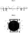
- the means for laying and supporting the substrates comprise, for example, movable laying arms 50 , as shown in FIGS. Figures 5 and 6 .
- the mobile loading / unloading lock MLL here comprises two laying arms 50 which slide under a substrate 51 and support it during the downward movement of the plate 52.
- the means for laying and supporting the substrates also comprise spacers 53. , through which the substrate rested on the tray, which allow the passage of the arms. It is therefore understood that at rest, the laying arms 50 have a recessed position in the mobile loading / unloading lock, so as to leave a passage for the basket.
- the laying arm 50 has a stop 54 for ensuring lateral support of the substrate.
- the positioning arms 50 are positioned facing each other, preferably at a height corresponding to the middle of the passage orifices 21 or 23 of the figure 2 respectively on the two walls perpendicular to the walls where these two orifices 21, 23 are located.
- the part of the arms intended to come into contact with the substrate is made of a material which avoids particulate contamination, for example in polyether ether ketone PEEK or a copolymer of tetrafluoroethylene and perfluoroethylene or perfluoroalkoxyalkane PFA.
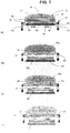
- the steps of unloading a substrate from a transport box 70 to a transfer chamber through an MLL device 71 are shown.
- the airlock MLL 71 is connected to the transport box 70 by its upper orifice 72. It is also connected for example to the transfer chamber of a device via an orifice 73 and to an EFEM module via an orifice 74.
- the transport box 70 shown is a box type SMIF having a lower opening closable by a door 75 provided with sealing means such as a seal 76.
- the transport box 70 contains a basket 77 in which can be arranged platelets 78 of substrate to be transported.
- the basket 77 comprises a series of parallel plates 79 adapted to each store a plate 78 .
- the mobile loading / unloading chamber 71 is designed to simultaneously accommodate several platelets 78 of substrates, then transfer them under vacuum one by one into a transfer chamber From the transport box 70, the basket 77 containing the platelets 78 of substrates is moved into the interior of the airlock 71 through the orifice 72.
- the device 71 comprises means for moving the basket 77 and blocking the trays 79 in a fixed position.
- the platen locking means are, for example, locking fingers 80 adapted to selectively block the downward movement of a selected plate, thereby preventing this plate and those which surmount it from falling further down the inside of the device. 71.
- the means for laying and supporting the substrate plates 78 comprise, for example, in combination shims 81 which raise the substrates and laying arms 82 which slide under the substrate plate 78 and support it during the movement towards the substrate. bottom of the plateau on which she rested.
- the means for moving the substrates 78 comprise, for example, a motorized shovel 83 which can lift the substrate wafer 78 resting on the laying arms 82 and move it towards the EFEM module via the orifice 74.
- the connection is sealed by the seal 76.
- the door 75 of the box 70 is unlocked if it has locking means.
- the door 75 of the box 70 and the door 84 of the device MLL 71 are made integral by a system that can be magnetic or mechanical.
- the door 84 of the device 71 is actuated, the door 75 of the box 70 goes down with the door 84 of the mobile loading / unloading lock MLL 71 and all the plates 79 forming the basket 77.
- the door of the airlock MLL 71 is stabilized to allow the locking fingers 80 to move forward to block the descent of the tray located just above that carrying the plate 78 of the substrate. transfer, thus preventing the further descent of a first group of trays 79a placed above the locking fingers 80.
- the group of trays 79b located below the locking fingers 80 continue their descent until the moment when the The desired substrate 78 is found a few millimeters above the plane of the laying arms 82.
- the laying arms 82 then advance, while the second group of trays 79b continues its descent, and the substrate is thus placed on the arm 82.
- a shovel 83 is introduced between the laying arms 82 to be positioned under the wafer 78 of the substrate. Then this shovel 83 raises the substrate which rested on the arms 82. The shovel 83 can then move by carrying the plate 78 of substrate to bring it into the EFEM module through the orifice 74.
- the figure 7d represents the transfer of the wafer 78 of the substrate into an EFEM module via the orifice 74, the transfer of the wafer 78 into the transfer chamber via the orifice 73 can of course be performed symmetrically in the same way without it being necessary to move the basket 77 or to change its orientation.
- a substrate processing plant is shown on the figure 8 . It comprises a first process chamber 90, in which a treatment of the substrates is carried out, communicating with a first transfer chamber 91 in which the substrate wafer is placed immediately before and after its treatment in the first process chamber 90.
- transfer chamber 91 communicates with an MLL device 92 which is simultaneously in communication with a second transfer chamber 93, itself connected to a second process chamber 94 in which another treatment of the substrates takes place.
- the loading / unloading lock MLL 92 also communicates with a transport box 95, for example of the SMIF type.
- the substrate wafers can thus be transferred one by one from the first process chamber 90 to the second process chamber 94 through the airlock MLL 92.
- the wafers can be placed temporarily waiting in the transport box 95 before loading in one or the other of the process chambers.
- the device according to the invention or MLL mobile loading / unloading lock, associated with a transport box which is connected to it, can be used in a large number of applications involving the manipulation of substrates.
- the figure 9 represents an installation adapted to some of these applications.
- the process chamber 100 communicates with the transfer chamber 102 which itself communicates with a first loading / unloading chamber 103 connected to a transport box 104.
- the airlock 103 can be used to connect to an EFEM module 105 to which a or a plurality of transport boxes 106 may be connected.
- the transfer chamber 102 also communicates with a second loading / unloading chamber 107, itself connected to a transport box 108, also connected to the EFEM module 105.
- the possibility of simultaneously connecting a second loading / unloading chamber to the chamber transfer 102 makes it possible to create a parallel circuit or to process an urgent batch, for example a qualification substrate, by putting another batch on hold.
- a first application of the device according to the invention is the intermediate storage of the substrate wafers without separation of the airlock MLL 103, 107 of the installation comprising the process chamber 100.
- a complete batch comprising several substrates to be treated must be divided into two parts.
- Each of the half batches is respectively placed in a transport box 106, for example of FOUP type which can be connected simultaneously to the EFEM module 105, itself connected to the mobile loading / unloading lock MLL 103, 107.
- the substrates are then transferred one by one from the transport box 106 to a basket disposed in a first airlock MLL 103 via the EFEM module 105 by means of the robot shovel of the EFEM module 105. Then each substrate is transferred from the first airlock MLL 103 to the process chamber 100 for processing, via the transfer chamber 102 through the robot shovel of the transfer chamber 102. Upon completion of the processing in the process chamber 100, the substrate is transferred to a second MLL lock 107 also connected to the transfer chamber 102, which thus makes it possible to vacuum store the treated substrates without contact with the substrates which have not yet been treated, remained in the first airlock MLL 103, and thus to avoid any contamination. .
- a second application is the qualification of a process ("hot lot" in English) to make it possible to check whether the processing facilities have kept the same specifications, and thus to qualify a chain of processing equipment that enters the different stages. of a process.
- a first transport box 104 connected to a first mobile loading / unloading lock MLL 103 and containing the complete batch of substrates to be processed, waits under vacuum connected to the equipment.
- a second transport box 108 containing only one substrate is connected to a second mobile loading / unloading lock MLL 107.
- the qualifying substrate is transferred to the process chamber 100 for processing. It is then brought back into the second transport box 108 by the airlock MLL 107 to which the transport box 108 is connected.
- the second transport box 108 is then transported to another processing installation in order to carry out the same sequence of operations which has just been described, until the substrate has undergone all the steps of the process to be qualified on all the dedicated equipment.
- the substrate is analyzed; the results of this analysis make it possible to validate the processing equipment used in the production line to carry out this process, as well as the treatments that will be implemented.
- a decontamination substrate used in this particular application (“gather" in English) can be successively transferred to the different process chambers of a treatment plant and left a lapse of time in each process chamber. This operation decontaminates each room. As soon as the substrate has finished circulating in all the chambers of the treatment plant, the transport box 108 is disconnected from the airlock MLL 107 to allow the substrate to be recovered so that it can be analyzed or discarded.
- the MLL device may also be used to mix or supplement a batch of substrates contained in the transport box 104, 108 connected to an MLL lock 103, 107 with substrates coming from the transport box 106 communicating with the EFEM module 105 .
- These manipulations are performed today by devices called “sorter” or "store” in English.
- the transport box 104 is disconnected from the loading / unloading lock MLL 103.
- the lock chamber MLL 103 is put back to atmospheric pressure.
- the door of the chamber 103 is then open, giving access to the interior volume thereof to proceed with its maintenance.
- the installation can continue to work with the substrates coming from the second transport box 108 via the loading / unloading lock MLL 107. This represents a saving of time and significant cost for the manufacture of semiconductor components, compared to to the current situation which requires the complete shutdown of the installation. Indeed, the transfer chamber and the EFEM module must currently be disconnected from the loading / unloading chamber to allow access to the interior of the latter.
Landscapes
- Container, Conveyance, Adherence, Positioning, Of Wafer (AREA)
- Packaging Frangible Articles (AREA)
Claims (8)
- Vorrichtung (71), die geeignet ist, mit mindestens zwei Ausrüstungen zur Verarbeitung von Substraten zusammenzuwirken, wobei die Vorrichtung dichte Wände umfasst, die geeignet sind, das Vakuum unterstützen und bewahren zu können, umfassend:- eine erste Öffnung (73), umfassend Anschlussmittel an eine erste Ausrüstung, die unter einer Transferkammer und einer Verfahrenskammer ausgewählt ist,- eine zweite Öffnung (72), umfassend Anschlussmittel an eine Transportbox (70) von Substraten,- einen Korb (77), der dazu bestimmt ist, in einer Transportbox von Substraten enthalten zu sein, umfassend eine Reihe von gestapelten parallelen Platten (79), die geeignet sind, jeweils eine Substratscheibe (78) zu lagern, und Keile (53; 81), die zwischen den Platten (79) und den Substratscheiben (78) angeordnet sind, wobei der Korb (77) geeignet ist, innerhalb der Wände der Vorrichtung (71) transportiert zu werden;- Mittel zur Verlagerung des Korbs (77) von und zu der Transportbox,- Mittel (80) zur Feststellung der Platten (79) ,dadurch gekennzeichnet, dass sie ferner umfasst- eine dritte Öffnung (74), umfassend Anschlussmittel an eine zweite Ausrüstung, die unter einem EFEM-Modul und einer Transferkammer ausgewählt ist, und- Mittel zum Aufstellen und Halten (27) einer Substratscheibe (78) in einer gegebenen Position, die geeignet sind, mit Verlagerungsmitteln (83) der Substratscheibe (78) der ersten oder der zweiten Ausrüstung zusammenzuwirken, um ihren Durchgang durch die erste Öffnung (73) oder die dritte Öffnung (74) zu ermöglichen, wobei die Mittel zum Aufstellen und Halten (27) einer Substratscheibe (78) umfassen:- zwei verschiebbare Aufstellarme (50; 82), die einander gegenüber auf zwei Wänden der Vorrichtung positioniert sind, senkrecht zu den Wänden der Vorrichtung, wo sich die ersten und dritten Öffnungen befinden, und- die Keile (53; 81), die zwischen den Platten (79) und den Substratscheiben (78) angeordnet und geeignet sind, den Durchgang der Aufstellarme (50) zu gestatten.
- Vorrichtung nach Anspruch 1, ferner umfassend Betätigungsmittel einer Tür, um die Tür, die jeweils jede Öffnung verschließt, zu öffnen und zu schließen.
- Vorrichtung nach einem der Ansprüche 1 und 2, ferner umfassend Dichtungsmittel im Bereich der Kopplungszone einer Öffnung mit einer Ausrüstung.
- Vorrichtung nach einem der Ansprüche 1 bis 3, bei der die Feststellungsmittel der Platten Verriegelungsfinger umfassen, die mit Betätigungsmitteln von Fingern zusammenwirken.
- Vorrichtung nach Anspruch 4, bei der der Verriegelungsfinger mit einer Kerbe versehen ist, die mit der Platte zusammenwirkt.
- Anlage zur Verarbeitung von Substraten, umfassend eine Verfahrenskammer, die mit einer ersten Transferkammer in Verbindung steht, und mindestens eine Vorrichtung nach einem der Ansprüche 1 bis 5, die mit der ersten Transferkammer, mit einem EFEM-Modul oder einer zweiten Transferkammer und mit einer Transportbox in Verbindung steht.
- Anlage zur Verarbeitung von Substraten, umfassend eine Verfahrenskammer und mindestens eine Vorrichtung nach einem der Ansprüche 1 bis 5, die mit der Verfahrenskammer, mit einem EFEM-Modul oder einer Transferkammer und mit einer Transportbox in Verbindung steht.
- Verwendung der Anlage nach Anspruch 7 zur Zwischenlagerung der Substratscheiben ohne Trennung der Vorrichtung von der Anlage, und zum Sortieren einer Substratmenge oder des Gemisches von Substraten, die von unterschiedlichen Mengen kommen.
Applications Claiming Priority (1)
| Application Number | Priority Date | Filing Date | Title |
|---|---|---|---|
| FR0854753A FR2933812B1 (fr) | 2008-07-11 | 2008-07-11 | Dispositif de chargement/dechargement de substrats |
Publications (3)
| Publication Number | Publication Date |
|---|---|
| EP2144285A2 EP2144285A2 (de) | 2010-01-13 |
| EP2144285A3 EP2144285A3 (de) | 2013-10-23 |
| EP2144285B1 true EP2144285B1 (de) | 2018-10-17 |
Family
ID=40336528
Family Applications (1)
| Application Number | Title | Priority Date | Filing Date |
|---|---|---|---|
| EP09164594.5A Active EP2144285B1 (de) | 2008-07-11 | 2009-07-03 | Vorrichtung zum Be- und Entladen von Substraten |
Country Status (8)
| Country | Link |
|---|---|
| US (1) | US8480346B2 (de) |
| EP (1) | EP2144285B1 (de) |
| JP (2) | JP2011527525A (de) |
| KR (1) | KR101754429B1 (de) |
| CN (1) | CN102089855A (de) |
| FR (1) | FR2933812B1 (de) |
| TW (1) | TWI476856B (de) |
| WO (1) | WO2010003927A1 (de) |
Families Citing this family (10)
| Publication number | Priority date | Publication date | Assignee | Title |
|---|---|---|---|---|
| JP5278438B2 (ja) * | 2008-10-17 | 2013-09-04 | 日本電気株式会社 | 固定装置及び固定装置を用いた固定方法 |
| EP2727137B1 (de) * | 2011-06-28 | 2022-04-20 | Brooks Automation (Germany) GmbH | Halbleiterspeichersysteme und -verfahren |
| TWI593864B (zh) * | 2011-11-11 | 2017-08-01 | Sumco Corp | Semiconductor manufacturing plant |
| US10395959B2 (en) * | 2013-01-22 | 2019-08-27 | Brooks Automation, Inc. | Substrate transport |
| SG11201705507TA (en) | 2015-01-09 | 2017-08-30 | Applied Materials Inc | Substrate transfer mechanisms |
| DE102017207004A1 (de) * | 2017-04-26 | 2018-10-31 | Homag Gmbh | Vorrichtung zum Vereinzeln von Werkstücken |
| CN110970322B (zh) * | 2018-09-30 | 2024-07-09 | 上海微电子装备(集团)股份有限公司 | 一种芯片贴片设备及芯片贴片方法 |
| CN112912796B (zh) * | 2018-10-23 | 2025-02-25 | Asml荷兰有限公司 | 检查设备 |
| CN116368605A (zh) | 2020-10-02 | 2023-06-30 | 恩特格里斯公司 | 晶片容器及其尺寸调适系统 |
| US12564974B2 (en) * | 2021-08-18 | 2026-03-03 | Applied Materials, Inc. | Factory interface with redundancy |
Family Cites Families (19)
| Publication number | Priority date | Publication date | Assignee | Title |
|---|---|---|---|---|
| US3858732A (en) * | 1971-03-09 | 1975-01-07 | Kate Kemper | Magazine for stackable trays |
| US4162649A (en) * | 1977-05-18 | 1979-07-31 | Wiggins Teape Limited | Sheet stack divider |
| JP2643366B2 (ja) * | 1988-09-29 | 1997-08-20 | 松下電器産業株式会社 | トレー段積み装置 |
| JP3743023B2 (ja) * | 1995-06-13 | 2006-02-08 | アシスト シンコー株式会社 | ウエハ保管装置 |
| US6062798A (en) * | 1996-06-13 | 2000-05-16 | Brooks Automation, Inc. | Multi-level substrate processing apparatus |
| JPH1187459A (ja) * | 1997-07-09 | 1999-03-30 | Canon Inc | 基板搬送装置、半導体製造システムおよびデバイス製造方法 |
| US6962471B2 (en) * | 2000-10-26 | 2005-11-08 | Leica Microsystems Jena Gmbh | Substrate conveying module and system made up of substrate conveying module and workstation |
| DE10053232C2 (de) * | 2000-10-26 | 2002-10-10 | Leica Microsystems | Substrat-Zuführungsmodul und System aus Substrat-Zuführungsmodul und Arbeitsstation |
| JP2002359237A (ja) | 2001-05-30 | 2002-12-13 | Hitachi Kokusai Electric Inc | 基板処理装置および半導体装置の製造方法 |
| US20030002964A1 (en) * | 2001-06-27 | 2003-01-02 | Hee Wee Boon | Handler system incorporating a semi-automatic tray replacement apparatus and method of use |
| US6619903B2 (en) * | 2001-08-10 | 2003-09-16 | Glenn M. Friedman | System and method for reticle protection and transport |
| CN100423179C (zh) * | 2002-06-21 | 2008-10-01 | 应用材料股份有限公司 | 用于真空处理系统的传送处理室 |
| US6935828B2 (en) * | 2002-07-17 | 2005-08-30 | Transfer Engineering And Manufacturing, Inc. | Wafer load lock and magnetically coupled linear delivery system |
| US6696367B1 (en) * | 2002-09-27 | 2004-02-24 | Asm America, Inc. | System for the improved handling of wafers within a process tool |
| JP4270434B2 (ja) * | 2002-11-29 | 2009-06-03 | シャープ株式会社 | 基板移載装置並びに基板の取り出し方法および基板の収納方法 |
| EP1457829A1 (de) * | 2003-03-11 | 2004-09-15 | ASML Netherlands B.V. | Lithographische Projektionsanordnung, Gerät und Verfahren zur Substrathandhabung |
| JP4478440B2 (ja) * | 2003-12-02 | 2010-06-09 | キヤノン株式会社 | ロードロック装置および方法 |
| FR2902235B1 (fr) * | 2006-06-09 | 2008-10-31 | Alcatel Sa | Dispositif de transport, de stockage et de transfert de substrats |
| US7581916B2 (en) * | 2006-07-14 | 2009-09-01 | Ulvac-Phi, Inc. | Sample introduction and transfer system and method |
-
2008
- 2008-07-11 FR FR0854753A patent/FR2933812B1/fr not_active Expired - Fee Related
-
2009
- 2009-07-03 EP EP09164594.5A patent/EP2144285B1/de active Active
- 2009-07-06 CN CN2009801269031A patent/CN102089855A/zh active Pending
- 2009-07-06 WO PCT/EP2009/058527 patent/WO2010003927A1/en not_active Ceased
- 2009-07-06 KR KR1020117003200A patent/KR101754429B1/ko active Active
- 2009-07-06 JP JP2011525476A patent/JP2011527525A/ja active Pending
- 2009-07-07 US US12/459,716 patent/US8480346B2/en active Active
- 2009-07-08 TW TW098123073A patent/TWI476856B/zh active
-
2014
- 2014-03-25 JP JP2014061367A patent/JP5905504B2/ja active Active
Non-Patent Citations (1)
| Title |
|---|
| None * |
Also Published As
| Publication number | Publication date |
|---|---|
| JP2011527525A (ja) | 2011-10-27 |
| FR2933812B1 (fr) | 2010-09-10 |
| CN102089855A (zh) | 2011-06-08 |
| TW201017802A (en) | 2010-05-01 |
| FR2933812A1 (fr) | 2010-01-15 |
| JP5905504B2 (ja) | 2016-04-20 |
| WO2010003927A1 (en) | 2010-01-14 |
| US20100008748A1 (en) | 2010-01-14 |
| US8480346B2 (en) | 2013-07-09 |
| KR20110029174A (ko) | 2011-03-22 |
| EP2144285A2 (de) | 2010-01-13 |
| EP2144285A3 (de) | 2013-10-23 |
| TWI476856B (zh) | 2015-03-11 |
| JP2014170943A (ja) | 2014-09-18 |
| KR101754429B1 (ko) | 2017-07-06 |
Similar Documents
| Publication | Publication Date | Title |
|---|---|---|
| EP2144285A2 (de) | Vorrichtung zum Be- und Entladen von Substraten | |
| US11990358B2 (en) | Sealed substrate carriers and systems and methods for transporting substrates | |
| EP0892985B1 (de) | Transporteinrichtung für flache gegenstände und verfahren zum transferieren dieser gegenstände zwischen dieser einrichtung und einem behandlungsapparat | |
| KR100373803B1 (ko) | 반도체 처리용 로드록 장치 및 방법 | |
| TWI823166B (zh) | 電子設備製造裝置、系統及方法中的裝載端口操作 | |
| WO2007141447A1 (fr) | Dispositif de transport, de stockage et de transfert de substrats | |
| TW200416775A (en) | Loadport apparatus and method for use thereof | |
| FR2668301A1 (fr) | Procede et installation de transfert sans contamination. | |
| CN108428654B (zh) | 基板处理系统和基板输送方法 | |
| EP2588392A1 (de) | Vorrichtung zur bearbeitung von transport- und lagerbehältern | |
| KR101530024B1 (ko) | 기판 처리 모듈, 이를 포함하는 기판 처리 장치 및 기판 전달 방법 | |
| US20100189532A1 (en) | Inline-type wafer conveyance device | |
| EP1973153A1 (de) | Dichter Behälter zum Transport und zur Lagerung von Halbleitersubstraten | |
| EP1780775A1 (de) | Einrichtung zur vertikalen wärmebehandlung und verfahren zu ihrem betrieb | |
| JP2018093087A (ja) | 基板処理装置 | |
| KR101661217B1 (ko) | 로드 포트 그리고 그것을 갖는 클러스터 설비 | |
| EP2144276A2 (de) | Entlüftungsvorrichtung und Verfahren | |
| US20220122861A1 (en) | Semiconductor device manufacturing system and method for manufacturing semiconductor device | |
| CN115101457A (zh) | 晶圆前端传送系统和半导体处理设备 |
Legal Events
| Date | Code | Title | Description |
|---|---|---|---|
| PUAI | Public reference made under article 153(3) epc to a published international application that has entered the european phase |
Free format text: ORIGINAL CODE: 0009012 |
|
| AK | Designated contracting states |
Kind code of ref document: A2 Designated state(s): AT BE BG CH CY CZ DE DK EE ES FI FR GB GR HR HU IE IS IT LI LT LU LV MC MK MT NL NO PL PT RO SE SI SK SM TR |
|
| RAP1 | Party data changed (applicant data changed or rights of an application transferred) |
Owner name: ADIXEN VACUUM PRODUCTS |
|
| PUAL | Search report despatched |
Free format text: ORIGINAL CODE: 0009013 |
|
| AK | Designated contracting states |
Kind code of ref document: A3 Designated state(s): AT BE BG CH CY CZ DE DK EE ES FI FR GB GR HR HU IE IS IT LI LT LU LV MC MK MT NL NO PL PT RO SE SI SK SM TR |
|
| AX | Request for extension of the european patent |
Extension state: AL BA RS |
|
| RIC1 | Information provided on ipc code assigned before grant |
Ipc: H01L 21/677 20060101ALI20130918BHEP Ipc: H01L 21/67 20060101AFI20130918BHEP |
|
| 17P | Request for examination filed |
Effective date: 20140417 |
|
| RBV | Designated contracting states (corrected) |
Designated state(s): AT BE BG CH CY CZ DE DK EE ES FI FR GB GR HR HU IE IS IT LI LT LU LV MC MK MT NL NO PL PT RO SE SI SK SM TR |
|
| 17Q | First examination report despatched |
Effective date: 20140526 |
|
| RAP1 | Party data changed (applicant data changed or rights of an application transferred) |
Owner name: PFEIFFER VACUUM |
|
| GRAP | Despatch of communication of intention to grant a patent |
Free format text: ORIGINAL CODE: EPIDOSNIGR1 |
|
| STAA | Information on the status of an ep patent application or granted ep patent |
Free format text: STATUS: GRANT OF PATENT IS INTENDED |
|
| INTG | Intention to grant announced |
Effective date: 20180507 |
|
| GRAS | Grant fee paid |
Free format text: ORIGINAL CODE: EPIDOSNIGR3 |
|
| GRAA | (expected) grant |
Free format text: ORIGINAL CODE: 0009210 |
|
| STAA | Information on the status of an ep patent application or granted ep patent |
Free format text: STATUS: THE PATENT HAS BEEN GRANTED |
|
| AK | Designated contracting states |
Kind code of ref document: B1 Designated state(s): AT BE BG CH CY CZ DE DK EE ES FI FR GB GR HR HU IE IS IT LI LT LU LV MC MK MT NL NO PL PT RO SE SI SK SM TR |
|
| REG | Reference to a national code |
Ref country code: GB Ref legal event code: FG4D Free format text: NOT ENGLISH |
|
| REG | Reference to a national code |
Ref country code: CH Ref legal event code: EP |
|
| REG | Reference to a national code |
Ref country code: IE Ref legal event code: FG4D Free format text: LANGUAGE OF EP DOCUMENT: FRENCH |
|
| REG | Reference to a national code |
Ref country code: DE Ref legal event code: R096 Ref document number: 602009055075 Country of ref document: DE Ref country code: AT Ref legal event code: REF Ref document number: 1054978 Country of ref document: AT Kind code of ref document: T Effective date: 20181115 |
|
| REG | Reference to a national code |
Ref country code: NL Ref legal event code: MP Effective date: 20181017 |
|
| REG | Reference to a national code |
Ref country code: LT Ref legal event code: MG4D |
|
| REG | Reference to a national code |
Ref country code: AT Ref legal event code: MK05 Ref document number: 1054978 Country of ref document: AT Kind code of ref document: T Effective date: 20181017 |
|
| PG25 | Lapsed in a contracting state [announced via postgrant information from national office to epo] |
Ref country code: NL Free format text: LAPSE BECAUSE OF FAILURE TO SUBMIT A TRANSLATION OF THE DESCRIPTION OR TO PAY THE FEE WITHIN THE PRESCRIBED TIME-LIMIT Effective date: 20181017 |
|
| PG25 | Lapsed in a contracting state [announced via postgrant information from national office to epo] |
Ref country code: ES Free format text: LAPSE BECAUSE OF FAILURE TO SUBMIT A TRANSLATION OF THE DESCRIPTION OR TO PAY THE FEE WITHIN THE PRESCRIBED TIME-LIMIT Effective date: 20181017 Ref country code: LV Free format text: LAPSE BECAUSE OF FAILURE TO SUBMIT A TRANSLATION OF THE DESCRIPTION OR TO PAY THE FEE WITHIN THE PRESCRIBED TIME-LIMIT Effective date: 20181017 Ref country code: AT Free format text: LAPSE BECAUSE OF FAILURE TO SUBMIT A TRANSLATION OF THE DESCRIPTION OR TO PAY THE FEE WITHIN THE PRESCRIBED TIME-LIMIT Effective date: 20181017 Ref country code: FI Free format text: LAPSE BECAUSE OF FAILURE TO SUBMIT A TRANSLATION OF THE DESCRIPTION OR TO PAY THE FEE WITHIN THE PRESCRIBED TIME-LIMIT Effective date: 20181017 Ref country code: IS Free format text: LAPSE BECAUSE OF FAILURE TO SUBMIT A TRANSLATION OF THE DESCRIPTION OR TO PAY THE FEE WITHIN THE PRESCRIBED TIME-LIMIT Effective date: 20190217 Ref country code: BG Free format text: LAPSE BECAUSE OF FAILURE TO SUBMIT A TRANSLATION OF THE DESCRIPTION OR TO PAY THE FEE WITHIN THE PRESCRIBED TIME-LIMIT Effective date: 20190117 Ref country code: PL Free format text: LAPSE BECAUSE OF FAILURE TO SUBMIT A TRANSLATION OF THE DESCRIPTION OR TO PAY THE FEE WITHIN THE PRESCRIBED TIME-LIMIT Effective date: 20181017 Ref country code: HR Free format text: LAPSE BECAUSE OF FAILURE TO SUBMIT A TRANSLATION OF THE DESCRIPTION OR TO PAY THE FEE WITHIN THE PRESCRIBED TIME-LIMIT Effective date: 20181017 Ref country code: NO Free format text: LAPSE BECAUSE OF FAILURE TO SUBMIT A TRANSLATION OF THE DESCRIPTION OR TO PAY THE FEE WITHIN THE PRESCRIBED TIME-LIMIT Effective date: 20190117 Ref country code: LT Free format text: LAPSE BECAUSE OF FAILURE TO SUBMIT A TRANSLATION OF THE DESCRIPTION OR TO PAY THE FEE WITHIN THE PRESCRIBED TIME-LIMIT Effective date: 20181017 |
|
| PG25 | Lapsed in a contracting state [announced via postgrant information from national office to epo] |
Ref country code: GR Free format text: LAPSE BECAUSE OF FAILURE TO SUBMIT A TRANSLATION OF THE DESCRIPTION OR TO PAY THE FEE WITHIN THE PRESCRIBED TIME-LIMIT Effective date: 20190118 Ref country code: PT Free format text: LAPSE BECAUSE OF FAILURE TO SUBMIT A TRANSLATION OF THE DESCRIPTION OR TO PAY THE FEE WITHIN THE PRESCRIBED TIME-LIMIT Effective date: 20190217 Ref country code: SE Free format text: LAPSE BECAUSE OF FAILURE TO SUBMIT A TRANSLATION OF THE DESCRIPTION OR TO PAY THE FEE WITHIN THE PRESCRIBED TIME-LIMIT Effective date: 20181017 |
|
| REG | Reference to a national code |
Ref country code: DE Ref legal event code: R097 Ref document number: 602009055075 Country of ref document: DE |
|
| PG25 | Lapsed in a contracting state [announced via postgrant information from national office to epo] |
Ref country code: CZ Free format text: LAPSE BECAUSE OF FAILURE TO SUBMIT A TRANSLATION OF THE DESCRIPTION OR TO PAY THE FEE WITHIN THE PRESCRIBED TIME-LIMIT Effective date: 20181017 Ref country code: IT Free format text: LAPSE BECAUSE OF FAILURE TO SUBMIT A TRANSLATION OF THE DESCRIPTION OR TO PAY THE FEE WITHIN THE PRESCRIBED TIME-LIMIT Effective date: 20181017 Ref country code: DK Free format text: LAPSE BECAUSE OF FAILURE TO SUBMIT A TRANSLATION OF THE DESCRIPTION OR TO PAY THE FEE WITHIN THE PRESCRIBED TIME-LIMIT Effective date: 20181017 |
|
| PLBE | No opposition filed within time limit |
Free format text: ORIGINAL CODE: 0009261 |
|
| STAA | Information on the status of an ep patent application or granted ep patent |
Free format text: STATUS: NO OPPOSITION FILED WITHIN TIME LIMIT |
|
| PG25 | Lapsed in a contracting state [announced via postgrant information from national office to epo] |
Ref country code: SK Free format text: LAPSE BECAUSE OF FAILURE TO SUBMIT A TRANSLATION OF THE DESCRIPTION OR TO PAY THE FEE WITHIN THE PRESCRIBED TIME-LIMIT Effective date: 20181017 Ref country code: RO Free format text: LAPSE BECAUSE OF FAILURE TO SUBMIT A TRANSLATION OF THE DESCRIPTION OR TO PAY THE FEE WITHIN THE PRESCRIBED TIME-LIMIT Effective date: 20181017 Ref country code: EE Free format text: LAPSE BECAUSE OF FAILURE TO SUBMIT A TRANSLATION OF THE DESCRIPTION OR TO PAY THE FEE WITHIN THE PRESCRIBED TIME-LIMIT Effective date: 20181017 Ref country code: SM Free format text: LAPSE BECAUSE OF FAILURE TO SUBMIT A TRANSLATION OF THE DESCRIPTION OR TO PAY THE FEE WITHIN THE PRESCRIBED TIME-LIMIT Effective date: 20181017 |
|
| 26N | No opposition filed |
Effective date: 20190718 |
|
| PG25 | Lapsed in a contracting state [announced via postgrant information from national office to epo] |
Ref country code: SI Free format text: LAPSE BECAUSE OF FAILURE TO SUBMIT A TRANSLATION OF THE DESCRIPTION OR TO PAY THE FEE WITHIN THE PRESCRIBED TIME-LIMIT Effective date: 20181017 |
|
| PG25 | Lapsed in a contracting state [announced via postgrant information from national office to epo] |
Ref country code: MC Free format text: LAPSE BECAUSE OF FAILURE TO SUBMIT A TRANSLATION OF THE DESCRIPTION OR TO PAY THE FEE WITHIN THE PRESCRIBED TIME-LIMIT Effective date: 20181017 |
|
| REG | Reference to a national code |
Ref country code: CH Ref legal event code: PL |
|
| GBPC | Gb: european patent ceased through non-payment of renewal fee |
Effective date: 20190703 |
|
| PG25 | Lapsed in a contracting state [announced via postgrant information from national office to epo] |
Ref country code: TR Free format text: LAPSE BECAUSE OF FAILURE TO SUBMIT A TRANSLATION OF THE DESCRIPTION OR TO PAY THE FEE WITHIN THE PRESCRIBED TIME-LIMIT Effective date: 20181017 |
|
| REG | Reference to a national code |
Ref country code: BE Ref legal event code: MM Effective date: 20190731 |
|
| PG25 | Lapsed in a contracting state [announced via postgrant information from national office to epo] |
Ref country code: GB Free format text: LAPSE BECAUSE OF NON-PAYMENT OF DUE FEES Effective date: 20190703 |
|
| PG25 | Lapsed in a contracting state [announced via postgrant information from national office to epo] |
Ref country code: CH Free format text: LAPSE BECAUSE OF NON-PAYMENT OF DUE FEES Effective date: 20190731 Ref country code: LI Free format text: LAPSE BECAUSE OF NON-PAYMENT OF DUE FEES Effective date: 20190731 Ref country code: LU Free format text: LAPSE BECAUSE OF NON-PAYMENT OF DUE FEES Effective date: 20190703 Ref country code: BE Free format text: LAPSE BECAUSE OF NON-PAYMENT OF DUE FEES Effective date: 20190731 |
|
| PG25 | Lapsed in a contracting state [announced via postgrant information from national office to epo] |
Ref country code: IE Free format text: LAPSE BECAUSE OF NON-PAYMENT OF DUE FEES Effective date: 20190703 |
|
| PG25 | Lapsed in a contracting state [announced via postgrant information from national office to epo] |
Ref country code: CY Free format text: LAPSE BECAUSE OF FAILURE TO SUBMIT A TRANSLATION OF THE DESCRIPTION OR TO PAY THE FEE WITHIN THE PRESCRIBED TIME-LIMIT Effective date: 20181017 |
|
| PG25 | Lapsed in a contracting state [announced via postgrant information from national office to epo] |
Ref country code: HU Free format text: LAPSE BECAUSE OF FAILURE TO SUBMIT A TRANSLATION OF THE DESCRIPTION OR TO PAY THE FEE WITHIN THE PRESCRIBED TIME-LIMIT; INVALID AB INITIO Effective date: 20090703 Ref country code: MT Free format text: LAPSE BECAUSE OF FAILURE TO SUBMIT A TRANSLATION OF THE DESCRIPTION OR TO PAY THE FEE WITHIN THE PRESCRIBED TIME-LIMIT Effective date: 20181017 |
|
| PG25 | Lapsed in a contracting state [announced via postgrant information from national office to epo] |
Ref country code: MK Free format text: LAPSE BECAUSE OF FAILURE TO SUBMIT A TRANSLATION OF THE DESCRIPTION OR TO PAY THE FEE WITHIN THE PRESCRIBED TIME-LIMIT Effective date: 20181017 |
|
| P01 | Opt-out of the competence of the unified patent court (upc) registered |
Effective date: 20230524 |
|
| PGFP | Annual fee paid to national office [announced via postgrant information from national office to epo] |
Ref country code: DE Payment date: 20250730 Year of fee payment: 17 |
|
| PGFP | Annual fee paid to national office [announced via postgrant information from national office to epo] |
Ref country code: FR Payment date: 20250729 Year of fee payment: 17 |
|
| REG | Reference to a national code |
Ref country code: DE Ref legal event code: R079 Ref document number: 602009055075 Country of ref document: DE Free format text: PREVIOUS MAIN CLASS: H01L0021670000 Ipc: H10P0072000000 |