EP2144384A1 - Mobilstation und Basisstation - Google Patents
Mobilstation und Basisstation Download PDFInfo
- Publication number
- EP2144384A1 EP2144384A1 EP09164811A EP09164811A EP2144384A1 EP 2144384 A1 EP2144384 A1 EP 2144384A1 EP 09164811 A EP09164811 A EP 09164811A EP 09164811 A EP09164811 A EP 09164811A EP 2144384 A1 EP2144384 A1 EP 2144384A1
- Authority
- EP
- European Patent Office
- Prior art keywords
- reception quality
- antenna
- mobile station
- unit
- delay
- Prior art date
- Legal status (The legal status is an assumption and is not a legal conclusion. Google has not performed a legal analysis and makes no representation as to the accuracy of the status listed.)
- Granted
Links
Images






Classifications
-
- H—ELECTRICITY
- H04—ELECTRIC COMMUNICATION TECHNIQUE
- H04B—TRANSMISSION
- H04B17/00—Monitoring; Testing
- H04B17/20—Monitoring; Testing of receivers
- H04B17/25—Monitoring; Testing of receivers taking multiple measurements
- H04B17/253—Monitoring; Testing of receivers taking multiple measurements measuring at different locations or reception points
-
- H—ELECTRICITY
- H04—ELECTRIC COMMUNICATION TECHNIQUE
- H04L—TRANSMISSION OF DIGITAL INFORMATION, e.g. TELEGRAPHIC COMMUNICATION
- H04L1/00—Arrangements for detecting or preventing errors in the information received
- H04L1/0001—Systems modifying transmission characteristics according to link quality, e.g. power backoff
- H04L1/0015—Systems modifying transmission characteristics according to link quality, e.g. power backoff characterised by the adaptation strategy
-
- H—ELECTRICITY
- H04—ELECTRIC COMMUNICATION TECHNIQUE
- H04L—TRANSMISSION OF DIGITAL INFORMATION, e.g. TELEGRAPHIC COMMUNICATION
- H04L1/00—Arrangements for detecting or preventing errors in the information received
- H04L1/02—Arrangements for detecting or preventing errors in the information received by diversity reception
- H04L1/06—Arrangements for detecting or preventing errors in the information received by diversity reception using space diversity
Definitions
- the present invention relates to a mobile station, and a base station ready for adaptive modulation.
- Adaptive modulation is a technique for changing the transmission format in accordance with the reception level at the reception end. Selecting an appropriate transmission format at various points in time will enable communications of a satisfactory level even in the fading environment.
- a device at the transmission end performs such adaptive modulation using the quality of reception at the reception end.
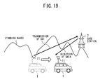
- a device at the reception end sends information about the measured reception quality, i.e., CQI (Channel Quality Indicator), to the transmission end, and the device at the transmission end determines the transmission format based on the information about the sent reception quality (refer to FIG. 19 ).
- CQI Channel Quality Indicator
- the CQI is measured by an antenna 11 provided on a communications device mounted in a vehicle 1.
- the resulting CQI is transmitted to a base station 2.
- the base station 2 returns, to the vehicle 1, data in the transmission format corresponding to the provided CQI.
- the problem here is that when such data is provided to the vehicle 1, the vehicle 1 is already at a different location.
- the vehicle 1 moves further before it is provided with the data, and thus the level of the reception quality of the antenna 11 may be different from the level at the time of transmitting the CQI. It is thus highly likely that the transmission format of the data provided by the base station 2 is not suitable for the present reception quality.
- AMC Adaptive Modulation and Coding
- HSDPA High Speed Downlink Packet Access
- a mobile station provided with first and second antennas with a distance therebetween includes a reception quality measurement unit that measures, when the mobile station moves in a direction from a location of the first antenna toward a location of the second antenna, a reception quality of a radio signal provided by a base station via the second antenna; a notification unit that notifies the base station of the reception quality measured by the reception quality measurement unit; and a reception processing unit that performs a reception process on a radio signal that is transmitted by the base station, which performs adaptive modulation based on the reception quality notified by the reception unit, and is received via the first antenna.
- a base station includes a reception unit that receives a notification of a reception quality from a mobile station, which includes first and second antennas with a distance therebetween and moves in a direction from a location of the first antenna toward a location of the second antenna, the reception quality being measured by the mobile station for a radio signal that is transmitted by the base station and received by the mobile station via the second antenna; an adaptive modulation control unit that performs adaptive modulation control on a transmitting signal based on the reception quality; and a transmission unit that transmits the transmitting signal in accordance with the adaptive modulation control to allow reception thereof by the mobile station via the first antenna.
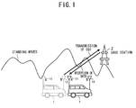
- FIG. 1 is a diagram explaining an adaptive modulation method of a first embodiment
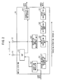
- FIG. 2 is an example of a configuration of a mobile station of the first embodiment
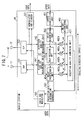
- FIG. 3 is an example of a configuration of a base station
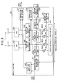
- FIG. 4 is an example of a configuration of a mobile station of a second embodiment
- FIG. 5 is an example of a configuration of a mobile station of a third embodiment
- FIG. 6 is a diagram explaining a result of throughput simulation when AMC is performed with HSDPA
- FIG. 7 is an example of a configuration of a mobile station of a fourth embodiment
- FIG. 8 is an example of a configuration of a mobile station of a fifth embodiment
- FIG. 9 is a diagram explaining, by a temporal-change waveform, an example of a correlation between the levels of reception quality
- FIG. 10 is an example of a configuration of a mobile station of a sixth embodiment
- FIG. 11 is an example of a configuration of a mobile station of a seventh embodiment
- FIG. 12 is a diagram explaining a vehicle mounted with a mobile station of an eighth embodiment during a turn
- FIG. 13 is an example of a configuration of the mobile station of the eighth embodiment.
- FIG. 14 is a diagram explaining a turning vehicle mounted with a mobile station of a ninth embodiment
- FIG. 15 is an example of a configuration of the mobile station of the ninth embodiment.
- FIG. 16 is an example of a configuration of a mobile station of a tenth embodiment
- FIG. 17 is a diagram explaining, by a temporal-change waveform, an example of a correlation between the intensity levels of radio waves;
- FIG. 18 is a diagram explaining an example of a fading environment.
- FIG. 19 is a diagram explaining the general outline of the adaptive modulation.
- a mobile station is provided with first and second antennas with a distance therebetween.
- the mobile station is provided with a reception quality measurement unit, a notification unit, and a reception processing unit.
- the reception quality measurement unit measures, when the mobile station moves in a direction from the location of the first antenna toward the location of the second antenna, the reception quality of a radio signal provided by a base station via the second antenna.
- the notification unit notifies the base station of the reception quality being a measurement result of the reception quality measurement unit.
- the reception processing unit performs a reception process on the radio signal received via the first antenna after being provided by the base station that performs adaptive modulation control based on the reception quality notified by the notification unit.
- the second antenna is disposed a predetremined distance away from the first antenna that receives data in the traveling direction, and the reception quality of the second antenna is notified to the base station with some delay in accordance with the time needed for the mobile station to move the distance between the first and second antennas.
- FIG. 1 is a diagram explaining an adaptive modulation method.
- a communications device mounted in the vehicle 1 is provided with an antenna 12 in addition to the antenna 11.
- the antenna 12 is located a certain distance away from the location of the antenna 11 in the traveling direction of the vehicle 1.
- the fading is mainly caused by standing waves in space.
- the reception quality measured by the antenna 12 will be at or close to the level of the reception quality to be measured when the antenna 11 reaches the location of the antenna 12.
- the timing of transmitting information about the reception quality is adjusted as to find a location match between where the reception quality of the antenna 12 is measured, and where the antenna 11 is provided with data in a transmission format determined based on the reception quality of the antenna 12.
- the antenna 11 is always able to receive data in a transmission format adapted to the reception quality, thereby being able to increase the throughput even when the vehicle 1 is moving at a high speed.
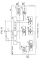
- FIG. 2 is an example of a configuration of the mobile station 10.
- the mobile station 10 is configured to include the antenna 11, the antenna 12, a duplicator (hereinafter, referred to as "DUP") 121, a demodulator and decoder 131, a reception quality measurement unit 142, a speed acquisition unit 151, a delay determining unit 152, a delay processing unit 153, a reception quality information generator 161, and a coder and modulator 162.
- DUP duplicator
- the antennas 11 and 12 are both used for transmission and reception of radio waves for radio communications use.
- the antenna 12 is disposed at a location away from the location of the antenna 11 by a distance L in the traveling direction of the mobile station 10.
- the DUP 121 accepts an input of a signal coming from the antenna 11, and outputs the signal received by the antenna 11.
- the demodulator and decoder 131 subjects the signal provided by the DUP 121 to processes of demodulation and decoding, thereby reproducing user data for output.
- the processes of demodulation and decoding to be performed by the demodulator and decoder 131 as such may be executed differently depending on the transmission format, which is determined based on the signal provided by the DUP 121.
- the reception quality measurement unit 142 is provided to measure the reception quality of the radio waves received by the antenna 12.
- the reception quality may be expressed as an SIR (Signal-to-Interference Ratio) value, for example.
- the speed acquisition unit 151 acquires the speed of the mobile station 10 moving in the traveling direction. The moving speed may be acquired based on the rotation frequency of the tires or other methods while the mobile station 10 is mounted in the vehicle, for example.
- the delay determining unit 152 determines a delay amount to adjust the timing of notifying the base station 2 of the reception quality measured by the reception quality measurement unit 142.
- the delay amount T is calculated by the following equation 1, where the distance between the antennas 11 and 12 is "L”, the speed acquired by the speed acquisition unit 151 is "v”, and the time until data in any corresponding transmission format arrives after information about the reception quality is transmitted to the base station 2 is "D":
- the time for the mobile station 10 to move 10 cm is calculated as
- the delay amount T will be 2 ms because the time until the data in the corresponding transmission format arrives after the information about the reception quality is transmitted to the base station 2 is 10 ms.
- the transmission format of the data received by the antenna 11 will be the transmission format best suited for the reception quality.
- the faster moving speed "v” and the longer distance "L” the transmission format of the data to be received by the antenna 11 will more likely be adapted to the reception quality, thereby allowing improvement of the throughput.
- the throughput may be improved with a delay amount T of 2ms.
- the delay processing unit 153 delays the timing of outputting, to the reception quality information generator 161, the reception quality measured by the reception quality measurement unit 142 with a delay amount determined by the delay determining unit 152.
- the reception quality information generator 161 uses the reception quality provided as such, the reception quality information generator 161 generates information about the reception quality being used to notify the base station 2 of the reception quality.
- the reception quality information generator 161 generates information about the reception quality by converting the SIR value into a CQI using a conversion table or the like made in advance.
- the reception quality information generator 161 includes, in the information about the reception quality, a value indicating that the notifying reception quality is accurate.
- the base station is often set to select the transmission format adapted to a reception quality lower than the notified reception quality. This is due to the assumption that, in the high-speed fading environment, the actual reception quality is lower than the reception quality notified by a wireless communications terminal.
- the base station With the value included in the information about the reception quality indicating that the reception quality is accurate, the base station is able to select a transmission format adapted to the notified reception quality, thereby being able to improve the throughput.
- the coder and modulator 162 subjects user data and information about the reception quality generated by the delay processing unit 153 to the processes of coding and modulation, and outputs the result to the DUP 121 for transmission from the antenna 11.
- the delay processing unit 153 delays the output from the reception quality measurement unit 142.
- the delay processing unit 153 may delay the output from the reception quality information generator 161.
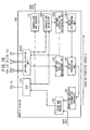
- FIG. 3 is a function block diagram illustrating the configuration of the base station 2.
- the base station 2 is configured to include an antenna 21, a DUP 22, a demodulator and decoder 23, a transmission format determining unit 24, and a coder and modulator 25.
- the antenna 21 is used for transmission and reception of radio waves for use with radio communications.
- the DUP 22 accepts an input of a signal coming from the antenna 21, and outputs the signal received by the antenna 21.
- the demodulator and decoder 23 subjects the signal provided by the DUP 22 to the processes of demodulation and decoding, thereby reproducing user data, information about the reception quality, and the like for output.
- the transmission format determining unit 24 determines the transmission format based on the reception quality information provided by the demodulator and decoder 23. The transmission format determining unit 24 makes a selection of the transmission format depending on whether or not the reception quality information includes the value indicating that the reception quality is accurate. If the reception quality information includes no value indicating that the reception quality is accurate, the transmission format determining unit 24 selects a transmission format considered the most suitable for the reception quality that is lower than the notified reception quality by a certain value. On the other hand, when the reception quality information includes a value indicating that the reception quality is accurate, the transmission format determining unit 24 selects a transmission format the most suitable for the notified reception quality.
- the coder and modulator 25 subjects the user data and the like to the processes of coding and modulation in accordance with the transmission format determined by the transmission format determining unit 24. The result is then forwarded to the DUP 22 for transmission from the antenna 21.
- the antenna 12 is disposed at a location a predetermined distance away from the antenna 11 for use of data reception in the traveling direction, and the reception quality of the antenna 12 is forwarded to the base station 2 with a delay amount in accordance with the distance between the antennas, the moving speed of the mobile station 10, and the like.
- Exemplified in the first embodiment is the case of using the two antennas, and using three or more antennas will increase the throughput to a further extent.
- a second embodiment an example of using three antennas for adaptive modulation is described.Components in the second embodiment provided with the same reference numerals as in the first embodiment shall not be described again.
- FIG. 4 is an example of a configuration of a mobile station 20 of the second embodiment.
- the mobile station 20 is configured to include the antennas 11 and 12, an antenna 13, the DUP 121, the demodulator and decoder 131, the reception quality measurement unit 141, a reception quality measurement unit 243, the speed acquisition unit 151, a delay determining unit 252, the delay processing unit 153, a delay processing unit 254, a weight determining unit 261, calculators 262a and 262b, a reception quality combining unit 271, the reception quality information generator 161, and the coder and modulator 162.
- the antenna 13 is used for the transmission and reception of radio waves for use with radio communications, and is disposed at a location away from the location of the antenna 12 by the distance L in the traveling direction of the mobile station 20.
- the reception quality measurement unit 243 is a device similar to the reception quality measurement unit 142, and is operated to measure the reception quality of the radio waves received by the antenna 13.
- the delay determining unit 252 determines a delay amount to adjust the timing of notifying the base station 2 of the reception quality measured by each of the reception quality measurement units 142 and 243.
- the delay determining unit 252 delays the timing of notifying the reception quality by a delay amount calculated with the equation 1.
- the delay determining unit 252 delays the timing of notifying the reception quality by a delay amount T' calculated with the following equation 2.
- the delay processing unit 254 delays, for output, the reception quality measured by the reception quality measurement unit 243 by a delay amount determined by the delay determining unit 252.
- the weight determining unit 261 determines weights w1 and w2 in accordance with the speed acquired by the speed acquisition unit 151.
- the weight w1 is the weight to be multiplied by the reception quality provided by the delay processing unit 153
- the weight w2 is the one to be multiplied by the reception quality provided by the delay processing unit 254.
- the reception quality of the radio waves received by the antenna 12 is combined together with the reception quality of the radio waves received by the antenna 13, so that the reception quality of the antenna 11 to be measured in the future may be estimated with a higher accuracy compared to using only the reception quality of the radio waves received by the antenna 12.
- the calculator 262a multiplies the reception quality provided by the delay processing unit 153 by the weight w1.
- the calculator 262b multiplies the reception quality provided by the delay processing unit 254 by the weight w2.
- the reception quality combining unit 271 combines the output from the calculator 262a with the output from the calculator 262b, and outputs the resulting reception quality to the reception quality information generator 161. Note here that combining the reception quality is not restricted merely to addition, but various other calculation methods may also be used, e.g., calculation of an average value.
- the three antennas 11 to 13 are aligned in the traveling direction of the mobile station 20, and the reception quality of the radio waves received by the antenna 12 is combined with the reception quality of the radio waves received by the antenna 13 after weighting thereof with a delay amount in accordance with the respective distances from the antenna 11.
- Such a configuration can increase the estimation accuracy of the reception quality of the antenna 11, and increase the throughput.
- Exemplified in the first and second embodiments is the case of using the antennas 12 and 13 only to measure the reception quality, but using the antennas also for data transmission and reception can lead to an increase in the performance of transmission and reception.
- a modified version of the mobile station 10 that performs diversity reception using two antennas shall be described in the third embodiment.
- FIG. 5 is an example of a configuration of a mobile station 30 of the third embodiment.
- the mobile station 30 is configured to include the antennas 11 and 12, the DUP 121, a DUP 322, a demodulator and decoder 331, the reception quality measurement unit 142, the speed acquisition unit 151, the delay determining unit 152, the delay processing unit 153, a reception quality combining unit 371, the reception quality information generator 161, and the coder and modulator 162.
- the DUP 322 receives an input of a signal coming from the antenna 12, and outputs the signal received by the antenna 12.
- the demodulator and decoder 331 subjects the signal provided by each of the DUPs 121 and 322 to processes of demodulation and decoding, thereby reproducing user data for output.
- the processes of demodulation and decoding to be performed by the demodulator and decoder 331 as such are executed differently depending on the transmission format, which is determined based on the signals provided by the DUPs 121 and 322.
- the reception quality combining unit 371 combines the reception quality as a result of delaying by the delay processing unit the reception quality measured by the reception quality measurement unit 142 by the delay amount T together with the reception quality with no delay. The combination result is then forwarded to the reception quality information generator 161.
- the base station When a plurality of antennas are used to receive the radio waves, the base station is generally notified of the highest value of the measurement results of the reception quality by the respective antennas.
- the reception quality at the time of data reception by the antenna 11 may be estimated due to the delay process, but the reception quality by the antenna 12 cannot be estimated. Accordingly, in the adaptive modulation method in this embodiment, the base station is notified of the result of combining the reception quality of the antenna 11 together with that of the antenna 12 using the latest value as is.
- the reception quality of the antenna 11 may be assigned more weight than the reception quality by the antenna 12 before combination thereof because the antenna 11 is expected to have the higher reception quality in consideration of the delay amount.
- FIG. 6 is a diagram explaining a result of throughput simulation when AMC is performed with HSDPA.
- the vertical axis in FIG. 6 indicates the throughput
- the horizontal axis indicates the correlation value between the SIR value at the time of measurement of the reception quality and the SIR value at the time of data reception.
- the correlation value of the horizontal axis takes the value of 1 when the mobile station 30 is not moving, and takes the value of 0 when the mobile station 30 is moving at a very high speed.
- the high-speed movement of the mobile station generally causes about 30 percent degradation of properties.
- using the adaptive modulation method of this embodiment leads to an improvement of properties of about 10 percent.
- the antenna 12 originally provided for measurement of the reception quality may also be used for data transmission and reception so that the properties of transmission and reception can be favorably improved.
- the first to third embodiments are cases in which the traveling direction of the mobile station is limited to one direction.
- the mobile station when the mobile station is mounted in a rail car, for example, the mobile station may be moved not only in the traveling direction but also in the opposite direction.
- a modified version of the mobile station 30 which enables optimization of the throughput even when the mobile station 30 is moved in the direction opposite to the traveling direction is described.
- FIG. 7 is an example of a configuration of a mobile station 40 of the fourth embodiment.
- the mobile station 40 is configured to include the antennas 11 and 12, the DUPs 121 and 322, the demodulator and decoder 331, a reception quality measurement unit 441, the reception quality measurement unit 142, the speed acquisition unit 151, a delay determining unit 452, the delay processing unit 153, a delay processing unit 454, a weight determining unit 461, calculators 462a to 462d, a reception quality combining unit 471, the reception quality information generator 161, and the coder and modulator 162.
- the reception quality measurement unit 441 is provided to measure the reception quality of the radio waves received by the antenna 11.
- the reception quality may be expressed as an SIR value, for example.
- the delay determining unit 452 determines a delay amount for adjusting the timing of notifying the base station 2 of the reception quality based on the equation 1 described above.
- the resulting delay amount T is forwarded to both the delay processing units 153 and 454.
- the delay processing unit 454 forwards the reception quality measured by the reception quality measurement unit 441 with the delay amount determined by the delay determining unit 452.
- the weight determining unit 461 determines weights w1 to w4 in accordance with the speed acquired by the speed acquisition unit 151.
- the weight w1 is the weight to be multiplied by the reception quality with a delay amount provided by the delay processing unit 454, and the weight w2 is the weight to be multiplied by the reception quality measured by the reception quality measurement unit 441 and includes no delay.
- the weight w3 is the weight to be multiplied by the reception quality measured by the reception quality measurement unit 142, and includes a delay amount provided by the delay processing unit 153.
- the weight w4 is the weight to be multiplied by the reception quality measured by the reception quality measurement unit 142, and includes no delay.
- the speed acquisition unit 151 acquires a speed of a positive value when the mobile station 40 moves in the direction from the antenna 11 toward the antenna 12, and acquires a speed of a negative value when the mobile station 40 moves in the direction from the antenna 12 toward the antenna 11.
- the throughput may also be improved when the mobile station 40 moves in the direction opposite to the traveling direction.
- the calculator 462a multiplies the reception quality provided by the delay processing unit 454 by the weight w1.
- the calculator 462b multiplies the reception quality provided by the reception quality measurement unit 441 by the weight w2.
- the calculator 462c multiplies the the reception quality provided by the delay processing unit 153 by the weight w3.
- the calculator 462d multiplies the reception quality provided by the reception quality measurement unit 142 by the weight w4.
- the reception quality combining unit 471 combines together the outputs from the calculators 462a to 462d, and outputs the resulting reception quality to the reception quality information generator 161.
- the reception quality of the antenna 11 is measured in addition to that of the antenna 12, and the speed acquired by the speed acquisition unit 151 is used as a basis to change the weight for each of the measurement results. This accordingly allows for an increase of the throughput when the mobile station 40 moves not only in one direction but also in the direction opposite thereto.
- the first to fourth embodiments are cases where the mobile station determines the delay time for notification of the reception quality through acquisition of data related to the moving speed thereof from the outside.
- the mobile station may be configured to determine the delay time without the supply of data related to the moving speed thereof from the outside.
- a modified version of the mobile station 40 that determines the delay time without receiving a supply of data related to the moving speed thereof from the outside is described.
- FIG. 8 is an example of a configuration of a mobile station 50 of the fifth embodiment.
- the mobile station 50 is configured to include the antennas 11 and 12, the DUPs 121 and 322, the demodulator and decoder 331, the reception quality measurement unit 441, the reception quality measurement unit 142, a correlation calculator 555, a maximum correlation determining unit 556, a delay determining unit 552, the delay processing units 153 and 454, a weight determining unit 561, the calculators 462a to 462d, the reception quality combining unit 471, the reception quality information generator 161, and the coder and modulator 162.
- the correlation calculator 555 stores two types of reception quality for a predetermined period of time.
- the reception quality types include one reception quality type measured by the reception quality measurement unit 441, and one reception quality type measured by the reception quality measurement unit 142.
- the correalation calclulator calculates correlation between waveforms expressing the change, in time, of these two types of reception quality.
- the correlation calculator 555 calculates, in stages, the temporal-change waveform of the correlation between the reception quality measured by the reception quality measurement unit 441 and the reception quality measured by the reception quality measurement unit 142. This calculation of the correlation is performed while the temporal-change waveform of the reception quality measured by the reception quality measurement unit 441 is being shifted in the direction of a time axis in stages of ⁇ t. Such a correlation calculation may be performed in any known manner.
- the maximum correlation determining unit 556 makes a comparison among the correlation results derived by the correlation calculator 555 for all of the stages, and acquires the cumulative value of ⁇ t at the stage showing the highest value among the correlation results. The maximum correlation determining unit 556 then forwards the resulting cumulative value of ⁇ t to the other components such as the delay processing units 153 and 454, and the weight determining unit 561.
- FIG. 9 illustrates an example of a temporal-change waveform of a correlation between levels of reception quality.
- the timing difference at the stage showing the highest value among the correlation results of FIG. 8 i.e., timing difference tmax, corresponds to the cumulative value of ⁇ t at that stage.
- timing difference tmax corresponds to the cumulative value of ⁇ t at that stage. Note here that, in the example of FIG. 8 , only the correlation corresponding to the timing difference in the positive direction is calculated. However, the correlation corresponding to the timing difference in the negative direction may also calculated which allows for the calculation when the mobile station 50 moves in the direction opposite to the traveling direction.
- the delay determining unit 552 calculates the delay amount T using the following equation 3, where " ⁇ t” indicates the input of a cumulative value of ⁇ t, and “D” indicates the time before data in any corresponding transmission format is provided after the reception quality information is transmitted to the base station 2:
- the delay determining unit 552 then forwards the resulting delay amount T to the other components, such as the delay processing units 153 and 454, and the weight determining unit 561.
- the reception quality of the antenna 12 may almost be the same as that of the antenna 11 after a certain length of time. Accordingly, the waveform derived by shifting the temporal change waveform of the reception quality measured by the reception quality measurement unit 441 and shifted a specific length of time along the time axis is expected to substantially match the temporal change waveform of the reception quality measured by the reception quality measurement unit 142.
- the delay determining unit 552 is able to determine any appropriate delay amount without an input of the moving speed.
- the reception quality to be measured in the future will be estimated using only the reception quality of the radio waves received by the antenna 12 disposed on the side in the traveling direction, thereby leading to the same effects as those derived by the configuration of FIG. 5 .
- the delay amount is determined based on the correlation between the reception quality of the antenna 11 and that of the antenna 12. This accordingly enables the selection of any optimum delay time without the supply of data related to the moving speed of the mobile station from the outside.
- the correlation of the reception quality is used as such as a basis to determine the delay amount, but alternatively, a pilot signal or the like may be used as a reference to determine the delay amount based on the correlation between the intensity of the radio waves received by the antenna 11 and the intensity of the radio waves received by the antenna 12.
- the distance between the antennas is considered significant.
- the delay amount to be calculated by the equation 1 will be a negative value, thereby failing to optimally adjust the delay time.
- the distance L between the antennas is too long, this may cause a large change of the standing waves during the delay of notification of the reception quality. As a result, it is highly likely that the transmission format for the data coming from the base station will not be optimum..
- the distance L between the antennas is preferably adjusted so that the result of the equation 1, i.e., delay amount T, takes a value as small as possible in the positive range. Accordingly, in the sixth embodiment, a modified version of the mobile station 10 with which the distance L between the antennas is appropriately adjusted in accordance with the moving speed of the mobile station is described.
- FIG. 10 is an example of a configuration of a mobile station 60 of the sixth embodiment.
- the mobile station 60 is configured to include the antennas 11 and 12, the DUP 121, an antenna drive unit 623, the demodulator and decoder 131, the reception quality measurement unit 142, the speed acquisition unit 151, a delay determining unit 652, the delay processing unit 153, the reception quality information generator 161, and the coder and modulator 162.
- the antenna drive unit 623 moves the antenna 12 forward and backward along the same axis as the traveling direction in accordance with the speed acquired by the speed acquisition unit 151. Specifically, the antenna drive unit 623 controls the antenna 12 by position in such a manner that the delay amount T satisfies 0 ⁇ T ⁇ Th.
- the delay amount T here derived by the equation 1 above using the speed acquired by the speed acquisition unit 151.
- Th denotes a sufficiently short length of time with which any influence of a change of the standing waves is negligible.
- the antenna drive unit 623 notifies the delay determining unit 652 of the distance between the antennas 11 and 12.
- the delay determining unit 652 determines the delay amount to adjust the timing of notifying the reception quality to the base station 2 using the equation 1 above, with the speed acquired by the speed acquisition unit 151, and the distance between the antennas notified by the antenna drive unit 623. The resulting delay is forwarded to the delay processing unit 153.
- the moving speed is used as a basis to adjust the distance between the antennas, optimizing the distance between the antennas and increasing the throughput irrespective of the moving speed.
- the antenna 12 is configured to be movable, but alternatively, the antenna 11, or both the antennas 11 and 12 may be configured to be movable.
- the sixth embodiment is an example of an antenna configured to be movable to keep an optimum the distance between the antennas.
- a plurality of antennas may be provided to measure the reception quality with varying distances from the antenna used for data reception, and if this is the configuration, effects similar to the above embodiments may be also achieved.
- the seventh embodiment a modified version of the mobile station 10 with which a plurality of antennas are provided to measure the reception quality to keep an optimum distance among the antennas is described.
- FIG. 11 is an example of a configuration of a mobile station 70 of the seventh embodiment.
- the mobile station 70 is configured to include the antenna 11, antennas 12a to 12e, the DUP 121, an antenna selection unit 724, the demodulator and decoder 131, the reception quality measurement unit 142, the speed acquisition unit 151, a delay determining unit 752, the delay processing unit 153, the reception quality information generator 161, and the coder and modulator 162.
- the antennas 12a to 12e are disposed at locations of various distances away from the location of the antenna 11 in the traveling direction of the mobile station 70.
- the antenna selection unit 724 calculates the delay amount L for each of the antennas 12a to 12e using the equation 1 above using the speed acquired by the speed acquisition unit 151 and the distance from the antenna 11.
- the antenna selection unit 724 selects any of the antennas 12a to 12e whose resulting delay amount T is equal to or larger than 0, and is the smallest among all the antennas 12a to 12e.
- the antenna selection unit 724 then forwards a signal received by the selected antenna to the reception quality measurement unit 142, and notifies the delay determining unit 752 of the distance between the selected antenna and the antenna 11.
- the delay determining unit 752 determines the delay amount to adjust the timing of notifying the reception quality to the base station 2 using the equation 1 above, with the speed acquired by the speed acquisition unit 151, and the distance between the antennas notified by the antenna selection unit 724. The resulting delay amount is forwarded to the delay processing unit 153.
- a plurality of antennas are provided to measure the reception quality, and an optimum antenna may be selected therefrom in accordance with the moving speed, thereby improving the distance between the antennas and increasing the throughput irrespective of the moving speed of the mobile station.
- the antennas it is desirable to place the antennas so that an antenna to measure the reception quality and an antenna used for data reception are both aligned along the traveling direction.
- the direction along which the antennas are disposed deviates from the traveling direction because the traveling direction will be directed inward from the front of the vehicle or the like.
- the reception quality of the antenna disposed on the side of the traveling direction will not always be the same as that to be measured in the future for the remaining antennas disposed therebehind, and the delay amount to be calculated by the equation 1 above may not be optimum, thereby resulting in a possibility of a reduction in the throughput.
- a modified version of the mobile station 10 with which the antennas are to be aligned along the traveling direction even when a vehicle or the like is making a turn is described.
- FIG. 12 is a diagram explaining the vehicle 1 mounted with a mobile station of the eighth embodiment, during a turn.
- the antennas 11 and 12 are both disposed on an antenna rotation unit 825.
- the antenna rotation unit 825 is configured to be directed freely about an axis 825a, and is operated to align the antennas 11 and 12 along the traveling direction of the vehicle 1.
- the antenna rotation unit 825 is rotated to align the antennas 11 and 12 with the angle y with respect to the front side of the vehicle 1.
- the antennas 11 and 12 are always aligned along the traveling direction, thereby favorably increasing the accuracy of the adaptive modulation.
- the traveling direction of the vehicle 1 may be acquired through conversion of the direction x of the front wheels of the vehicle 1 or of the steering angle of the vehicle 1, or may be acquired by an acceleration sensor provided on the vehicle 1 or on the mobile station 80.
- FIG. 13 is an example of a configuration of the mobile station 80 of the eighth embodiment.
- the mobile station 80 is configured to include the antennas 11 and 12, the antenna rotation unit 825, a traveling direction acquisition unit 826, an angle determining unit 827, the DUP 121, the demodulator and decoder 131, the reception quality measurement unit 142, the speed acquisition unit 151, the delay determining unit 152, the delay processing unit 153, the reception quality information generator 161, and the coder and modulator 162.
- the antenna rotation unit 825 changes the alignment direction of the antennas 11 and 12.
- the traveling direction acquisition unit 826 acquires information indicating the traveling direction of the mobile station 80. Based on the information acquired by the traveling direction acquisition unit 826 as such, the angle determining unit 827 calculates the rotation angle for the antenna rotation unit 825 to align the antennas 11 and 12 along the traveling direction. The resulting angle is forwarded to the antenna rotation unit 825.
- the antennas 11 and 12 are aligned differently depending on any change of the traveling direction. This accordingly enables the alignment of the antennas 11 and 12 along the traveling direction, and increases the accuracy of the adaptive modulation.
- the eighth embodiment is an example of rotating and moving the antennas to align the antennas always along the traveling direction. Similar effects may also be achieved if a plurality of antennas to measure the reception quality are provided at varying directions from an antenna for use in data reception.
- a modified version of the mobile station 10 in which a plurality of antennas to measure the reception quality are provided at varying directions from an antenna for use in data reception is described.
- FIG. 14 is a diagram explaining the vehicle 1 mounted with a mobile station 90 of the ninth embodiment during a turn.
- the antennas 12a to 12e are disposed a to vary in directions from the antenna 11.
- any antenna located closest to the traveling direction of the vehicle 1 is selected, and the reception quality of the selected antenna is used for the adaptive modulation.
- the angle from the antenna 11 to the antenna 12b is the angle closest to the angle y , and so the reception quality of the antenna 12b is used for the adaptive modulation.
- the antenna 11direction of the vehicle 1 may be acquired through conversion of the direction x of the front wheels of the vehicle 1 or of the steering angle of the vehicle 1, or may be acquired by an acceleration sensor provided in the vehicle 1 or in the mobile station 90.
- FIG. 15 is an example of a configuration of the mobile station 90 of the ninth embodiment.
- the mobile station 90 is configured to include the antenna 11, the antennas 12a to 12e, an antenna selection unit 924, the traveling direction acquisition unit 826, the DUP 121, the demodulator and decoder 131, the reception quality measurement unit 142, the speed acquisition unit 151, the delay determining unit 152, the delay processing unit 153, the reception quality information generator 161, and the coder and modulator 162.
- the antenna selection unit 924 uses information acquired by the traveling direction acquisition unit 826 as a basis to select any of the antennas 12a to 12e located closest to the traveling direction of the mobile station 90 viewed from the antenna 11. The antenna selection unit 924 then forwards a signal received by the selected antenna to the reception quality measurement unit 142. When the antennas 12a to 12e are located at various distances from the antenna 11, the antenna selection unit 924 notifies the delay determining unit 152 of the distance between the selected antenna and the antenna 11.
- any of the antennas 12a to 12e may be selected in accordance with a change of the traveling direction. This accordingly enables the alignment of both the antenna to measure the reception quality and the antenna for data reception along the heading direction, and increases the accuracy of the adaptive modulation.
- the ninth embodiment is an example of selecting any antenna after acquiring the traveling direction of the mobile station from the outside.
- such an antenna selection can be made without the mobile station being provided with data related to the traveling direction from the outside.
- a modified version of the mobile station 90 with which an antenna selection is made without the supply of data related to the traveling direction from the outside is described.
- FIG. 16 is an example of a configuration of a mobile station 100 of the tenth embodiment.
- the mobile station 100 is configured to include the antenna 11, the antennas 12a to 12e, an antenna selection unit 1024, the DUP 121, the demodulator and decoder 131, a correlation calculator 1055, a maximum correlation determining unit 1056, the reception quality measurement unit 142, a delay determining unit 1052, the delay processing unit 153, the reception quality information generator 161, and the coder and modulator 162.
- the correlation calculator 1055 calculates the correlation between the intensity of the radio waves to be received by the antenna 11, and the intensity of the radio waves to be received by the antennas 12a to 12e.
- the correlation calculator 1055 uses a pilot signal or the like as a reference to measure the intensity of the radio waves to be received by the antenna 11, and the intensity of the radio waves to be received by the antennas 12a to 12e.
- the correlation calculator 1055 then calculates, in stages, with a shift of ⁇ t in stages in the time-axis direction, the temporal-change waveform of the correlation between the intensity of the radio waves received by the antenna 11, and the intensity of the radio waves received by the antenna 12a.
- the temporal-change waveforms here are those derived by measuring the intensity of such respective radio waves for a predetermined length of time.
- the correlation calculator 1055 calculates, in stages, with a shift of ⁇ t in the time-axis direction, the correlation as a temporal-change waveform of the intensity of the radio waves to be received by the antenna 11.
- the maximum correlation determining unit 1056 makes a comparison among the correlation results derived by the correlation calculator 1055, and determines which antenna shows the highest correlation value in which stage. The maximum correlation determining unit 1056 then acquires the cumulative value of At at the stage showing the highest value of the correlation. The maximum correlation determining unit 1056 then notifies the antenna selection unit 1024 which of the antennas 12a to 12e shows the highest value of the correlation, and forwards the resulting cumulative value of ⁇ t at the stage of the highest value of the correlation to the delay determining unit 1052.
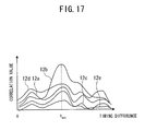
- FIG. 17 illustrates an example of a correlation of a temporal-change waveform of the intensity of the radio waves.
- FIG. 17 illustrates an example of a correlation in the case of FIG. 14 .
- the correlation with the antenna 12b shows the highest value.
- the timing difference tmax at the stage showing the highest value of the correlation corresponds to the cumulative value of ⁇ t at this stage.
- the maximum correlation determining unit 1056 forwards a signal corresponding to the antenna 12b to the antenna selection unit 1024, and outputs the timing difference tmax to the delay determining unit 1052.
- the antenna selection unit 1024 selects any of the antennas 12a to 12e notified by the maximum correlation determining unit 1056. The antenna selection unit 1024 then outputs a signal received by the selected antenna to the reception quality measurement unit 142. Note here that when the distance varies among the antennas 12a to 12e and the antenna 11, the antenna selection unit 1024 notifies the delay determining unit 1052 of the distance between the selected antenna and the antenna 11.
- the delay determining unit 1052 calculates the delay amount T using the equation 3 above, with the input of cumulative value of ⁇ t, and the time D before data in any corresponding transmission format is provided after the reception quality information is transmitted to the base station 2. The delay determining unit 1052 then forwards the resulting delay amount T to the delay processing unit 153.
- the correlation of intensity of the radio waves is used as a basis to select any of the antennas 12a to 12e.
- the antenna located in the traveling direction is selected to measure the reception quality, thereby increasing the accuracy of the adaptive modulation.
- the invention also provides a computer program or a computer program product for carrying out any of the methods described herein, and a computer readable medium having stored thereon a program for carrying out any of the methods described herein.
- a computer program embodying the invention may be stored on a computer-readable medium, or it could, for example, be in the form of a signal such as a downloadable data signal provided from an Internet website, or it could be in any other form.
Landscapes
- Engineering & Computer Science (AREA)
- Computer Networks & Wireless Communication (AREA)
- Signal Processing (AREA)
- Quality & Reliability (AREA)
- Physics & Mathematics (AREA)
- Electromagnetism (AREA)
- Mobile Radio Communication Systems (AREA)
- Radio Transmission System (AREA)
Applications Claiming Priority (1)
| Application Number | Priority Date | Filing Date | Title |
|---|---|---|---|
| JP2008178245A JP5223507B2 (ja) | 2008-07-08 | 2008-07-08 | 移動局および基地局 |
Publications (2)
| Publication Number | Publication Date |
|---|---|
| EP2144384A1 true EP2144384A1 (de) | 2010-01-13 |
| EP2144384B1 EP2144384B1 (de) | 2011-10-12 |
Family
ID=41198528
Family Applications (1)
| Application Number | Title | Priority Date | Filing Date |
|---|---|---|---|
| EP09164811A Not-in-force EP2144384B1 (de) | 2008-07-08 | 2009-07-07 | Mobilstation mit einer adaptiven Modulationssteuerung |
Country Status (4)
| Country | Link |
|---|---|
| US (1) | US8831526B2 (de) |
| EP (1) | EP2144384B1 (de) |
| JP (1) | JP5223507B2 (de) |
| AT (1) | ATE528873T1 (de) |
Cited By (3)
| Publication number | Priority date | Publication date | Assignee | Title |
|---|---|---|---|---|
| EP2771994A4 (de) * | 2011-10-24 | 2015-07-01 | Ericsson Telefon Ab L M | Auswahl eines transportformats zur übertragung von datenblöcken zwischen einer basisstation und einem mobilen endgerät |
| CN107636983A (zh) * | 2015-06-01 | 2018-01-26 | 华为技术有限公司 | 用于无线网络中有效链路发现的系统与方法 |
| WO2022028333A1 (zh) * | 2020-08-05 | 2022-02-10 | 华为技术有限公司 | 一种自动控制方法、电子设备及计算机可读存储介质 |
Families Citing this family (14)
| Publication number | Priority date | Publication date | Assignee | Title |
|---|---|---|---|---|
| WO2013089057A1 (ja) * | 2011-12-13 | 2013-06-20 | 日本電気株式会社 | 無線パラメータ制御システム、無線パラメータ制御装置、無線基地局、無線端末、無線パラメータ制御方法及びプログラム |
| KR20140117847A (ko) * | 2013-03-27 | 2014-10-08 | 한국전자통신연구원 | 이동체의 핸드오버 방법 및 이를 이용하는 이동체의 통신 장치 |
| CN105917661B (zh) * | 2014-01-14 | 2019-10-22 | 阿尔卑斯阿尔派株式会社 | 车辆通信装置 |
| JP6359359B2 (ja) * | 2014-07-02 | 2018-07-18 | アルプス電気株式会社 | 電子キー装置 |
| JP6481292B2 (ja) * | 2014-09-03 | 2019-03-13 | 株式会社ソシオネクスト | 受信回路及び受信方法 |
| WO2016149871A1 (zh) * | 2015-03-20 | 2016-09-29 | 华为技术有限公司 | 接收设备和接收信号的处理方法 |
| DE102015211336A1 (de) * | 2015-06-19 | 2016-12-22 | Bayerische Motoren Werke Aktiengesellschaft | Sendeempfänger, Fahrzeug, Verfahren und Computerprogramm für einen Sendeempfänger |
| JP6642352B2 (ja) * | 2016-02-03 | 2020-02-05 | 株式会社デンソー | 移動通信システム、通信装置 |
| US10756794B2 (en) | 2016-04-07 | 2020-08-25 | Lg Electronics Inc. | Method for reporting channel quality information in distributed antenna communication system and apparatus therefor |
| CN109906560B (zh) * | 2016-11-11 | 2021-12-10 | 三星电子株式会社 | 执行无线通信的车辆及其通信方法 |
| JP2019118092A (ja) * | 2017-12-27 | 2019-07-18 | パナソニック株式会社 | 基地局およびアンテナ制御方法 |
| US11165512B2 (en) * | 2018-05-23 | 2021-11-02 | Nec Corporation | Wireless communication identification device and wireless communication identification method |
| KR102424104B1 (ko) * | 2019-01-09 | 2022-07-22 | 삼성전자주식회사 | 무선 통신 시스템에서 전파 특성을 분석하기 위한 장치 및 방법 |
| JP7347512B2 (ja) | 2019-08-05 | 2023-09-20 | 株式会社デンソー | 端末装置及び端末装置における通信方法 |
Citations (3)
| Publication number | Priority date | Publication date | Assignee | Title |
|---|---|---|---|---|
| EP1887725A2 (de) * | 2002-04-30 | 2008-02-13 | QUALCOMM Incorporated | Verfahren und Vorrichtung zur Paketenformattierung |
| JP2008085419A (ja) * | 2006-09-26 | 2008-04-10 | Mitsubishi Electric Corp | 受信装置 |
| JP2008178245A (ja) | 2007-01-19 | 2008-07-31 | Denshi Kogaku Center:Kk | 瞬停発生装置 |
Family Cites Families (30)
| Publication number | Priority date | Publication date | Assignee | Title |
|---|---|---|---|---|
| US6996077B1 (en) * | 1997-07-03 | 2006-02-07 | Kabushiki Kaisha Toshiba | Satellite broadcasting system |
| JP2002152105A (ja) * | 2000-11-06 | 2002-05-24 | Foundation For Nara Institute Of Science & Technology | ディジタル通信を行う移動体のための送受信装置 |
| US9173175B2 (en) * | 2000-11-16 | 2015-10-27 | Sony Corporation | Information processing apparatus and communication apparatus |
| JP2003198426A (ja) | 2001-12-27 | 2003-07-11 | Mitsubishi Electric Corp | 適応変調無線通信装置 |
| CN1266982C (zh) * | 2002-02-07 | 2006-07-26 | 松下电器产业株式会社 | 无线电通信设备和传输速率确定方法 |
| JP4242606B2 (ja) * | 2002-06-20 | 2009-03-25 | 株式会社エヌ・ティ・ティ・ドコモ | 通信制御システム、通信制御方法、移動局及び基地局 |
| US7123924B2 (en) * | 2002-06-28 | 2006-10-17 | Interdigital Technology Corporation | Method and system for determining the speed and position of a mobile unit |
| JP2004180154A (ja) * | 2002-11-28 | 2004-06-24 | Matsushita Electric Ind Co Ltd | 基地局装置および適応変調方法 |
| JP3753698B2 (ja) * | 2003-02-07 | 2006-03-08 | 松下電器産業株式会社 | 無線送信装置および伝送レート決定方法 |
| US7573961B2 (en) * | 2003-09-03 | 2009-08-11 | Koninklijke Philips Electronics N.V. | Virtual-antenna receiver |
| JPWO2005036825A1 (ja) * | 2003-10-09 | 2006-12-28 | 松下電器産業株式会社 | 高速移動体の無線伝送システム |
| KR20060132918A (ko) * | 2004-02-26 | 2006-12-22 | 마쓰시다 일렉트릭 인더스트리얼 컴패니 리미티드 | 이동국 장치 및 이동국 장치에 있어서의 송신 안테나 선택방법 |
| KR100981514B1 (ko) * | 2004-12-30 | 2010-09-10 | 삼성전자주식회사 | 직교 주파수 분할 다중 접속 통신 시스템에서 부분 채널 정보 피드백을 이용한 적응 부채널 및 비트 할당 방법 |
| JP2006345429A (ja) | 2005-06-10 | 2006-12-21 | Matsushita Electric Ind Co Ltd | デジタル通信・放送に関する受信装置、受信方法、受信回路、およびプログラム |
| KR20070033115A (ko) * | 2005-09-20 | 2007-03-26 | 삼성전자주식회사 | 광대역 무선 접속 통신 시스템에서 적응 변조 및 부호화레벨 할당 시스템 및 방법 |
| WO2007043459A1 (ja) * | 2005-10-07 | 2007-04-19 | Nec Corporation | 複数の基地局と移動局によるmimo無線通信システム及び方法 |
| JP2007150906A (ja) * | 2005-11-29 | 2007-06-14 | Kyocera Corp | 基地局、無線通信端末及び無線通信システム |
| EP1808710A1 (de) * | 2006-01-11 | 2007-07-18 | International University Bremen Gmbh | Verfahren und Vorrichtung zur Bestimmung der Geschwindigkeit eines beweglichen Objekts |
| EP2005609B1 (de) * | 2006-03-24 | 2018-10-10 | Telefonaktiebolaget LM Ericsson (publ) | Verfahren und anorndung zur verwaltung eines referenzsignals zur aufwärtsstreckenkanalschätzung in einem kommunikationssystem |
| KR100958495B1 (ko) * | 2006-04-28 | 2010-05-17 | 후지쯔 가부시끼가이샤 | 수신 다이버시티 기능을 갖는 w-cdma 방식에 의한이동기, 및 그 시스템 |
| KR100809191B1 (ko) * | 2006-06-20 | 2008-02-29 | 엘지노텔 주식회사 | 이동 통신 시스템의 채널품질상태표시값 전송 장치 및 방법 |
| JP2008011285A (ja) * | 2006-06-30 | 2008-01-17 | Fujitsu Ltd | 送信電力制御装置及び送信電力制御方法 |
| JP2008042547A (ja) * | 2006-08-07 | 2008-02-21 | Fujitsu Ltd | 移動通信システム,基地局,端末装置及び送信制御方法 |
| US8755804B2 (en) * | 2006-08-18 | 2014-06-17 | Wifi Rail, Inc | System for providing redundant communication with mobile devices |
| KR100929089B1 (ko) * | 2006-11-28 | 2009-11-30 | 삼성전자주식회사 | 이동 통신 시스템에서 채널 품질 지시자 정보를 이용하여이동 단말의 속도를 추정하는 방법 및 장치 |
| US20080132173A1 (en) * | 2006-11-30 | 2008-06-05 | Korea Advanced Institute Of Science And Technology | Channel estimation apparatus and channel estimation method |
| KR20080041096A (ko) * | 2007-03-13 | 2008-05-09 | 엘지전자 주식회사 | 무선 통신 시스템에서 피드백 정보를 이용한 링크 적응방법 |
| JP4869997B2 (ja) * | 2007-03-20 | 2012-02-08 | 株式会社エヌ・ティ・ティ・ドコモ | チャネル品質情報報告方法、基地局及びユーザ端末 |
| US20090170500A1 (en) * | 2007-12-26 | 2009-07-02 | Kabushiki Kaisha Toshiba | Radio apparatus and radio communication method |
| US20100310005A1 (en) * | 2008-02-05 | 2010-12-09 | Yuhsuke Takagi | Mobile communication device, base station device, radio control method, and mobile communication system |
-
2008
- 2008-07-08 JP JP2008178245A patent/JP5223507B2/ja not_active Expired - Fee Related
-
2009
- 2009-07-07 US US12/498,602 patent/US8831526B2/en not_active Expired - Fee Related
- 2009-07-07 AT AT09164811T patent/ATE528873T1/de not_active IP Right Cessation
- 2009-07-07 EP EP09164811A patent/EP2144384B1/de not_active Not-in-force
Patent Citations (3)
| Publication number | Priority date | Publication date | Assignee | Title |
|---|---|---|---|---|
| EP1887725A2 (de) * | 2002-04-30 | 2008-02-13 | QUALCOMM Incorporated | Verfahren und Vorrichtung zur Paketenformattierung |
| JP2008085419A (ja) * | 2006-09-26 | 2008-04-10 | Mitsubishi Electric Corp | 受信装置 |
| JP2008178245A (ja) | 2007-01-19 | 2008-07-31 | Denshi Kogaku Center:Kk | 瞬停発生装置 |
Cited By (4)
| Publication number | Priority date | Publication date | Assignee | Title |
|---|---|---|---|---|
| EP2771994A4 (de) * | 2011-10-24 | 2015-07-01 | Ericsson Telefon Ab L M | Auswahl eines transportformats zur übertragung von datenblöcken zwischen einer basisstation und einem mobilen endgerät |
| CN107636983A (zh) * | 2015-06-01 | 2018-01-26 | 华为技术有限公司 | 用于无线网络中有效链路发现的系统与方法 |
| CN107636983B (zh) * | 2015-06-01 | 2020-08-07 | 华为技术有限公司 | 用于无线网络中有效链路发现的系统与方法 |
| WO2022028333A1 (zh) * | 2020-08-05 | 2022-02-10 | 华为技术有限公司 | 一种自动控制方法、电子设备及计算机可读存储介质 |
Also Published As
| Publication number | Publication date |
|---|---|
| US20100009636A1 (en) | 2010-01-14 |
| ATE528873T1 (de) | 2011-10-15 |
| US8831526B2 (en) | 2014-09-09 |
| JP2010021647A (ja) | 2010-01-28 |
| JP5223507B2 (ja) | 2013-06-26 |
| EP2144384B1 (de) | 2011-10-12 |
Similar Documents
| Publication | Publication Date | Title |
|---|---|---|
| EP2144384B1 (de) | Mobilstation mit einer adaptiven Modulationssteuerung | |
| US6928274B2 (en) | Receiver device for a mobile radiocommunication unit employing a speed estimator | |
| EP2449714B1 (de) | Justieren eines kanalqualitätsberichts in einem drahtlosen kommunikationsnetz | |
| KR20020032620A (ko) | 통신 단말 장치, 기지국 장치 및 통신 방법 | |
| KR101106692B1 (ko) | 다중입출력 통신시스템의 동작 모드 선택 장치 및 방법 | |
| US20190075569A1 (en) | Apparatus and method for wireless communications, and parameter optimization apparatus and method | |
| KR20030081464A (ko) | 기지국 장치, 통신 단말 장치 및 무선 통신 방법 | |
| EP2182650B1 (de) | Mobilstation und übertragungsdiversitäts-steuerverfahren | |
| JP3695571B2 (ja) | Cdma移動通信システムにおけるcdma受信装置および受信信号電力測定方法 | |
| CN101816126B (zh) | 用于在rf接收器装置中进行频率控制的装置和方法 | |
| US20050254563A1 (en) | Radio reception device and sir calculation method | |
| EP2068458A1 (de) | Funkkommunikationseinrichtung und funkkommunikationsverfahren | |
| CN102165713A (zh) | 信道预测系统、无线通信设备及信道预测方法 | |
| US10686637B2 (en) | Receiving apparatus and receiving method | |
| US8325859B2 (en) | Communication device and control method | |
| KR20050043470A (ko) | 이동통신시스템의 수신단에서의 주파수 오차 추정 및 결합기 | |
| JP2007288676A (ja) | 無線基地局および送信制御方法 | |
| KR100973778B1 (ko) | 이동 통신 단말기 및 이동 통신 방법 | |
| US7532685B2 (en) | Methods of controlling tracker bandwidth in wireless communication systems | |
| JP4565802B2 (ja) | データ受信装置およびデータ受信方法 | |
| KR20140076894A (ko) | 이동통신 시스템에서 적응적 채널 품질 계산 방법 및 장치 | |
| EP1881634B1 (de) | Adaptive Kommunikation für drahtlose Netzwerke | |
| JP7063276B2 (ja) | 通信装置および通信方法 | |
| JP2013183226A (ja) | 通信システムおよび送受信方法 | |
| JP4917956B2 (ja) | 無線通信装置及び信号処理方法 |
Legal Events
| Date | Code | Title | Description |
|---|---|---|---|
| PUAI | Public reference made under article 153(3) epc to a published international application that has entered the european phase |
Free format text: ORIGINAL CODE: 0009012 |
|
| AK | Designated contracting states |
Kind code of ref document: A1 Designated state(s): AT BE BG CH CY CZ DE DK EE ES FI FR GB GR HR HU IE IS IT LI LT LU LV MC MK MT NL NO PL PT RO SE SI SK SM TR |
|
| 17P | Request for examination filed |
Effective date: 20100707 |
|
| GRAP | Despatch of communication of intention to grant a patent |
Free format text: ORIGINAL CODE: EPIDOSNIGR1 |
|
| RTI1 | Title (correction) |
Free format text: MOBILE STATION WITH AN ADAPTIVE MODULATION CONTROL |
|
| GRAS | Grant fee paid |
Free format text: ORIGINAL CODE: EPIDOSNIGR3 |
|
| GRAA | (expected) grant |
Free format text: ORIGINAL CODE: 0009210 |
|
| AK | Designated contracting states |
Kind code of ref document: B1 Designated state(s): AT BE BG CH CY CZ DE DK EE ES FI FR GB GR HR HU IE IS IT LI LT LU LV MC MK MT NL NO PL PT RO SE SI SK SM TR |
|
| REG | Reference to a national code |
Ref country code: GB Ref legal event code: FG4D |
|
| REG | Reference to a national code |
Ref country code: CH Ref legal event code: EP |
|
| REG | Reference to a national code |
Ref country code: IE Ref legal event code: FG4D |
|
| REG | Reference to a national code |
Ref country code: DE Ref legal event code: R096 Ref document number: 602009003010 Country of ref document: DE Effective date: 20111208 |
|
| REG | Reference to a national code |
Ref country code: NL Ref legal event code: VDEP Effective date: 20111012 |
|
| LTIE | Lt: invalidation of european patent or patent extension |
Effective date: 20111012 |
|
| REG | Reference to a national code |
Ref country code: AT Ref legal event code: MK05 Ref document number: 528873 Country of ref document: AT Kind code of ref document: T Effective date: 20111012 |
|
| PG25 | Lapsed in a contracting state [announced via postgrant information from national office to epo] |
Ref country code: NO Free format text: LAPSE BECAUSE OF FAILURE TO SUBMIT A TRANSLATION OF THE DESCRIPTION OR TO PAY THE FEE WITHIN THE PRESCRIBED TIME-LIMIT Effective date: 20120112 Ref country code: IS Free format text: LAPSE BECAUSE OF FAILURE TO SUBMIT A TRANSLATION OF THE DESCRIPTION OR TO PAY THE FEE WITHIN THE PRESCRIBED TIME-LIMIT Effective date: 20120212 Ref country code: LT Free format text: LAPSE BECAUSE OF FAILURE TO SUBMIT A TRANSLATION OF THE DESCRIPTION OR TO PAY THE FEE WITHIN THE PRESCRIBED TIME-LIMIT Effective date: 20111012 Ref country code: BE Free format text: LAPSE BECAUSE OF FAILURE TO SUBMIT A TRANSLATION OF THE DESCRIPTION OR TO PAY THE FEE WITHIN THE PRESCRIBED TIME-LIMIT Effective date: 20111012 |
|
| PG25 | Lapsed in a contracting state [announced via postgrant information from national office to epo] |
Ref country code: SE Free format text: LAPSE BECAUSE OF FAILURE TO SUBMIT A TRANSLATION OF THE DESCRIPTION OR TO PAY THE FEE WITHIN THE PRESCRIBED TIME-LIMIT Effective date: 20111012 Ref country code: NL Free format text: LAPSE BECAUSE OF FAILURE TO SUBMIT A TRANSLATION OF THE DESCRIPTION OR TO PAY THE FEE WITHIN THE PRESCRIBED TIME-LIMIT Effective date: 20111012 Ref country code: PT Free format text: LAPSE BECAUSE OF FAILURE TO SUBMIT A TRANSLATION OF THE DESCRIPTION OR TO PAY THE FEE WITHIN THE PRESCRIBED TIME-LIMIT Effective date: 20120213 Ref country code: LV Free format text: LAPSE BECAUSE OF FAILURE TO SUBMIT A TRANSLATION OF THE DESCRIPTION OR TO PAY THE FEE WITHIN THE PRESCRIBED TIME-LIMIT Effective date: 20111012 Ref country code: SI Free format text: LAPSE BECAUSE OF FAILURE TO SUBMIT A TRANSLATION OF THE DESCRIPTION OR TO PAY THE FEE WITHIN THE PRESCRIBED TIME-LIMIT Effective date: 20111012 Ref country code: GR Free format text: LAPSE BECAUSE OF FAILURE TO SUBMIT A TRANSLATION OF THE DESCRIPTION OR TO PAY THE FEE WITHIN THE PRESCRIBED TIME-LIMIT Effective date: 20120113 Ref country code: HR Free format text: LAPSE BECAUSE OF FAILURE TO SUBMIT A TRANSLATION OF THE DESCRIPTION OR TO PAY THE FEE WITHIN THE PRESCRIBED TIME-LIMIT Effective date: 20111012 |
|
| PG25 | Lapsed in a contracting state [announced via postgrant information from national office to epo] |
Ref country code: CY Free format text: LAPSE BECAUSE OF FAILURE TO SUBMIT A TRANSLATION OF THE DESCRIPTION OR TO PAY THE FEE WITHIN THE PRESCRIBED TIME-LIMIT Effective date: 20111012 |
|
| PG25 | Lapsed in a contracting state [announced via postgrant information from national office to epo] |
Ref country code: DK Free format text: LAPSE BECAUSE OF FAILURE TO SUBMIT A TRANSLATION OF THE DESCRIPTION OR TO PAY THE FEE WITHIN THE PRESCRIBED TIME-LIMIT Effective date: 20111012 Ref country code: SK Free format text: LAPSE BECAUSE OF FAILURE TO SUBMIT A TRANSLATION OF THE DESCRIPTION OR TO PAY THE FEE WITHIN THE PRESCRIBED TIME-LIMIT Effective date: 20111012 Ref country code: EE Free format text: LAPSE BECAUSE OF FAILURE TO SUBMIT A TRANSLATION OF THE DESCRIPTION OR TO PAY THE FEE WITHIN THE PRESCRIBED TIME-LIMIT Effective date: 20111012 Ref country code: CZ Free format text: LAPSE BECAUSE OF FAILURE TO SUBMIT A TRANSLATION OF THE DESCRIPTION OR TO PAY THE FEE WITHIN THE PRESCRIBED TIME-LIMIT Effective date: 20111012 Ref country code: BG Free format text: LAPSE BECAUSE OF FAILURE TO SUBMIT A TRANSLATION OF THE DESCRIPTION OR TO PAY THE FEE WITHIN THE PRESCRIBED TIME-LIMIT Effective date: 20120112 |
|
| PLBE | No opposition filed within time limit |
Free format text: ORIGINAL CODE: 0009261 |
|
| STAA | Information on the status of an ep patent application or granted ep patent |
Free format text: STATUS: NO OPPOSITION FILED WITHIN TIME LIMIT |
|
| PG25 | Lapsed in a contracting state [announced via postgrant information from national office to epo] |
Ref country code: PL Free format text: LAPSE BECAUSE OF FAILURE TO SUBMIT A TRANSLATION OF THE DESCRIPTION OR TO PAY THE FEE WITHIN THE PRESCRIBED TIME-LIMIT Effective date: 20111012 Ref country code: RO Free format text: LAPSE BECAUSE OF FAILURE TO SUBMIT A TRANSLATION OF THE DESCRIPTION OR TO PAY THE FEE WITHIN THE PRESCRIBED TIME-LIMIT Effective date: 20111012 |
|
| 26N | No opposition filed |
Effective date: 20120713 |
|
| REG | Reference to a national code |
Ref country code: DE Ref legal event code: R097 Ref document number: 602009003010 Country of ref document: DE Effective date: 20120713 |
|
| PG25 | Lapsed in a contracting state [announced via postgrant information from national office to epo] |
Ref country code: AT Free format text: LAPSE BECAUSE OF FAILURE TO SUBMIT A TRANSLATION OF THE DESCRIPTION OR TO PAY THE FEE WITHIN THE PRESCRIBED TIME-LIMIT Effective date: 20111012 |
|
| PG25 | Lapsed in a contracting state [announced via postgrant information from national office to epo] |
Ref country code: MC Free format text: LAPSE BECAUSE OF NON-PAYMENT OF DUE FEES Effective date: 20120731 Ref country code: MK Free format text: LAPSE BECAUSE OF FAILURE TO SUBMIT A TRANSLATION OF THE DESCRIPTION OR TO PAY THE FEE WITHIN THE PRESCRIBED TIME-LIMIT Effective date: 20111012 |
|
| PG25 | Lapsed in a contracting state [announced via postgrant information from national office to epo] |
Ref country code: ES Free format text: LAPSE BECAUSE OF FAILURE TO SUBMIT A TRANSLATION OF THE DESCRIPTION OR TO PAY THE FEE WITHIN THE PRESCRIBED TIME-LIMIT Effective date: 20120123 |
|
| REG | Reference to a national code |
Ref country code: IE Ref legal event code: MM4A |
|
| PG25 | Lapsed in a contracting state [announced via postgrant information from national office to epo] |
Ref country code: FI Free format text: LAPSE BECAUSE OF FAILURE TO SUBMIT A TRANSLATION OF THE DESCRIPTION OR TO PAY THE FEE WITHIN THE PRESCRIBED TIME-LIMIT Effective date: 20111012 |
|
| PG25 | Lapsed in a contracting state [announced via postgrant information from national office to epo] |
Ref country code: IE Free format text: LAPSE BECAUSE OF NON-PAYMENT OF DUE FEES Effective date: 20120707 Ref country code: MT Free format text: LAPSE BECAUSE OF FAILURE TO SUBMIT A TRANSLATION OF THE DESCRIPTION OR TO PAY THE FEE WITHIN THE PRESCRIBED TIME-LIMIT Effective date: 20111012 |
|
| REG | Reference to a national code |
Ref country code: CH Ref legal event code: PL |
|
| PG25 | Lapsed in a contracting state [announced via postgrant information from national office to epo] |
Ref country code: LI Free format text: LAPSE BECAUSE OF NON-PAYMENT OF DUE FEES Effective date: 20130731 Ref country code: CH Free format text: LAPSE BECAUSE OF NON-PAYMENT OF DUE FEES Effective date: 20130731 Ref country code: TR Free format text: LAPSE BECAUSE OF FAILURE TO SUBMIT A TRANSLATION OF THE DESCRIPTION OR TO PAY THE FEE WITHIN THE PRESCRIBED TIME-LIMIT Effective date: 20111012 |
|
| PG25 | Lapsed in a contracting state [announced via postgrant information from national office to epo] |
Ref country code: LU Free format text: LAPSE BECAUSE OF NON-PAYMENT OF DUE FEES Effective date: 20120707 Ref country code: SM Free format text: LAPSE BECAUSE OF FAILURE TO SUBMIT A TRANSLATION OF THE DESCRIPTION OR TO PAY THE FEE WITHIN THE PRESCRIBED TIME-LIMIT Effective date: 20111012 |
|
| PG25 | Lapsed in a contracting state [announced via postgrant information from national office to epo] |
Ref country code: HU Free format text: LAPSE BECAUSE OF FAILURE TO SUBMIT A TRANSLATION OF THE DESCRIPTION OR TO PAY THE FEE WITHIN THE PRESCRIBED TIME-LIMIT Effective date: 20090707 |
|
| REG | Reference to a national code |
Ref country code: FR Ref legal event code: PLFP Year of fee payment: 8 |
|
| REG | Reference to a national code |
Ref country code: FR Ref legal event code: PLFP Year of fee payment: 9 |
|
| PGFP | Annual fee paid to national office [announced via postgrant information from national office to epo] |
Ref country code: FR Payment date: 20170613 Year of fee payment: 9 |
|
| PGFP | Annual fee paid to national office [announced via postgrant information from national office to epo] |
Ref country code: GB Payment date: 20170705 Year of fee payment: 9 Ref country code: DE Payment date: 20170705 Year of fee payment: 9 Ref country code: IT Payment date: 20170720 Year of fee payment: 9 |
|
| REG | Reference to a national code |
Ref country code: DE Ref legal event code: R119 Ref document number: 602009003010 Country of ref document: DE |
|
| GBPC | Gb: european patent ceased through non-payment of renewal fee |
Effective date: 20180707 |
|
| PG25 | Lapsed in a contracting state [announced via postgrant information from national office to epo] |
Ref country code: GB Free format text: LAPSE BECAUSE OF NON-PAYMENT OF DUE FEES Effective date: 20180707 Ref country code: FR Free format text: LAPSE BECAUSE OF NON-PAYMENT OF DUE FEES Effective date: 20180731 Ref country code: DE Free format text: LAPSE BECAUSE OF NON-PAYMENT OF DUE FEES Effective date: 20190201 |
|
| PG25 | Lapsed in a contracting state [announced via postgrant information from national office to epo] |
Ref country code: IT Free format text: LAPSE BECAUSE OF NON-PAYMENT OF DUE FEES Effective date: 20180707 |