EP2144456A1 - Aide auditive dotée d'un compartiment de batterie verrouillable - Google Patents
Aide auditive dotée d'un compartiment de batterie verrouillable Download PDFInfo
- Publication number
- EP2144456A1 EP2144456A1 EP09157698A EP09157698A EP2144456A1 EP 2144456 A1 EP2144456 A1 EP 2144456A1 EP 09157698 A EP09157698 A EP 09157698A EP 09157698 A EP09157698 A EP 09157698A EP 2144456 A1 EP2144456 A1 EP 2144456A1
- Authority
- EP
- European Patent Office
- Prior art keywords
- cover
- housing
- hearing aid
- designed
- actuating element
- Prior art date
- Legal status (The legal status is an assumption and is not a legal conclusion. Google has not performed a legal analysis and makes no representation as to the accuracy of the status listed.)
- Withdrawn
Links
Images

Classifications
-
- H—ELECTRICITY
- H04—ELECTRIC COMMUNICATION TECHNIQUE
- H04R—LOUDSPEAKERS, MICROPHONES, GRAMOPHONE PICK-UPS OR LIKE ACOUSTIC ELECTROMECHANICAL TRANSDUCERS; ELECTRIC HEARING AIDS; PUBLIC ADDRESS SYSTEMS
- H04R25/00—Electric hearing aids
- H04R25/60—Mounting or interconnection of hearing aid parts, e.g. inside tips, housings or to ossicles
- H04R25/602—Mounting or interconnection of hearing aid parts, e.g. inside tips, housings or to ossicles of batteries
-
- H—ELECTRICITY
- H01—ELECTRIC ELEMENTS
- H01M—PROCESSES OR MEANS, e.g. BATTERIES, FOR THE DIRECT CONVERSION OF CHEMICAL ENERGY INTO ELECTRICAL ENERGY
- H01M50/00—Constructional details or processes of manufacture of the non-active parts of electrochemical cells other than fuel cells, e.g. hybrid cells
- H01M50/20—Mountings; Secondary casings or frames; Racks, modules or packs; Suspension devices; Shock absorbers; Transport or carrying devices; Holders
- H01M50/204—Racks, modules or packs for multiple batteries or multiple cells
- H01M50/207—Racks, modules or packs for multiple batteries or multiple cells characterised by their shape
- H01M50/216—Racks, modules or packs for multiple batteries or multiple cells characterised by their shape adapted for button or coin cells
-
- Y—GENERAL TAGGING OF NEW TECHNOLOGICAL DEVELOPMENTS; GENERAL TAGGING OF CROSS-SECTIONAL TECHNOLOGIES SPANNING OVER SEVERAL SECTIONS OF THE IPC; TECHNICAL SUBJECTS COVERED BY FORMER USPC CROSS-REFERENCE ART COLLECTIONS [XRACs] AND DIGESTS
- Y02—TECHNOLOGIES OR APPLICATIONS FOR MITIGATION OR ADAPTATION AGAINST CLIMATE CHANGE
- Y02E—REDUCTION OF GREENHOUSE GAS [GHG] EMISSIONS, RELATED TO ENERGY GENERATION, TRANSMISSION OR DISTRIBUTION
- Y02E60/00—Enabling technologies; Technologies with a potential or indirect contribution to GHG emissions mitigation
- Y02E60/10—Energy storage using batteries
Definitions
- the invention relates to a lockable battery compartment cover for a hearing aid and a hearing aid with a lockable battery compartment.
- Hearing aids are generally carried out portable and therefore have a battery as an energy source for power supply.
- the battery has a relatively short life and must therefore be changed frequently by the hearing aid wearer.
- a provided with a cover, easily accessible battery compartment is provided in a hearing aid housing. Easy accessibility is particularly desirable for older hearing aid wearers with reduced fine motor and tactile skills.
- Hearing aids serve the care of hearing impaired persons, e.g. Hard of hearing, with individually adjusted amplified hearing signals. In most cases, hearing aids can also work in different, situation-adapted signal processing algorithms, so-called hearing programs, and are therefore programmable.
- a hardware programming interface is provided on a hearing aid, e.g. the today as quasi-standard standard CS44 connector. As a protection against contamination, moisture and unwanted contact of the contacts, the programming interface is often closed with a cover.
- Hearing aids often have additional hardware interfaces for connecting accessory devices, for example for connecting a so-called audio shoe. These other interfaces can also be provided with a cover.
- tinnitus therapy equipment e.g. so-called tinnitus maskers
- tinnitus maskers are used. These are in the design of the hearing aids similar or identical devices. However, their purpose is not or not only a suitable auditory signal amplification, but the generation of certain acoustic signals that serve to cover or mitigate tinnitus noise.
- hearing aid is used equally for hearing aids as well as for tinnitus therapy devices.
- a hearing aid is known with a battery charger, which is operable to remove the battery.
- the battery charger also serves as a switching device to turn the hearing aid off and on. It is lockable by a sliding blocking element, which releases the operation of the battery charger as a switching means in a first position and blocks to remove the battery. In a second position of the blocking element and the operation of the battery charger is released to remove the battery.
- a hearing aid device having a battery compartment that includes a battery compartment cover is known.
- the battery door is used to insert a battery and stops as soon as it is closed is, the electrical connection between the battery and hearing aid ago. It has a displaceable blocking element by means of which it can be locked and unlocked in the housing of the hearing aid.
- a battery charger for a hearing aid which serves for inserting a battery and establishing an electrical connection with the hearing aid.
- the battery door snaps into the housing of the hearing aid with a catch when it is closed.
- the closed position is supported by the magnetic field of a permanent magnet.
- the object of the invention is to provide a hearing aid housing with a lockable cover and a lockable cover for a hearing aid housing, which is easy to use, reliable in function, and inexpensive in design and manufacture.
- the invention solves this problem by a hearing aid and by a cover with the features of the independent claims.
- the operation of the lock simplifies. It does not need to be actuated several locking elements simultaneously and operated coordinated with each other.
- the operation of the lock is independent of the opening and closing movement of the cover. This additionally facilitates the operation of the lock. Due to the ease of operation, the opening requires a reduced concentration of the hearing aid wearer, so that the prerequisites are created to provide higher locking forces. This increases the security of the lock against accidental opening and against unintentional operation, for example by toddlers.
- the actuating element can advantageously be designed as a pushbutton. Any other embodiments, such as a lever, slider or rocker switch are also conceivable.
- the construction of the lock is relatively low due to the small number of construction elements kept simple. This further reduces the number of assembly steps and thus the production cost.
- the bars are designed as pins. This allows a particularly simple construction and particularly inexpensive production.
- particularly simple pen shapes e.g. cylindrical, can be selected.
- the wells in the housing of the hearing aid are designed as holes. This allows a particularly simple Konstrkution and inexpensive production while adapting to the execution, if the bars are designed as pins.
- circular holes represent a particularly simple form of the recesses, which are adapted to a cylindrical bar shape.
- the latch and the actuating element are designed as a one-piece component. This reduces the number of assembly steps in the production and thus the production cost. In addition, a reduction in the number of interacting parts simplifies the construction. And last but not least, an increase in reliability can be achieved by reducing the number of interacting parts.
- the bolt, the actuating element and in addition also the cover are designed as a one-piece component. This results in a further reduction in the number of parts and thus a further reduction in manufacturing costs.
- the at least consisting of bars and actuator component is designed partially elastic.
- the elastic forces can cause the bars of the Lockingsätig take the closed position and go only against the elastic forces in the ⁇ ffenposition. This is ensured by the use of elastic forces that the bars are not actuated actuator in the closed position.
- the actuating forces can be directed upon actuation of the actuating element such that they are brought into the ⁇ ffenposition by them the bolt.
- additional design elements are unnecessary, for example springs or permanent magnets for applying elastic or reversible closing forces. The reduction in the number of parts causes a reduction in the assembly steps in the production and thus the manufacturing cost and can increase the reliability of the construction.
- the bolt and the actuator made of plastic.
- Plastic for example, in injection molding or RSM process advantageous 3-dimensional component shapes can be realized.
- a battery charger for inserting a battery which is designed such that it can be introduced into a battery compartment of the hearing aid housing, and the cover is included as part of the battery charger.
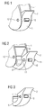
- FIG. 1 a section of a housing 1 of a hearing aid 3 with a cover 2 is shown schematically.
- the cover 2 closes with the edge of the housing 1 largely flush. It is part of a battery 5.
- the battery charger 5 is formed so that a battery not shown in the figure can be inserted.
- the battery can serve, for example, the power supply for the signal processing electronics of the hearing aid, also not shown.
- the cover 2 With the cover 2 closed, as shown in the figure, the battery charger 5 is inserted into a battery compartment of the housing 1 and thus the hearing aid is connected to an inserted into the battery charger 5 battery. Shown is the ready state.
- the cover 2 and the battery charger 5 form a common component.
- On the cover 2 components of a lock are provided.
- the lock serves to releasably secure the cover 2, and thus also the battery charger 5, to or in the housing 1.
- an actuating element 10 When the cover 2 is closed, an actuating element 10 can be seen as the only locking element of the cover.
- the actuating element 10 is a tactile or pressure element projecting from the image.
- the lock By actuating the actuating element 10, namely pressing, the lock is opened and the cover can be released.
- the lock On the side of the housing 1, the lock has an indentation 12, indicated in the drawing, which, above all, represents a depression of the inside of the housing 1 or the housing wall. It can, as in the figure, pass as a hole or hole through the housing wall. However, the recess 12 may also be formed only on the inner wall of the housing 1, so that it need not be visible from the outside.
- the side facing away from the viewing angle in the selected perspective side of the housing 1 also has a at the same place, so symmetrically arranged recess 12. Seen from the interior of the housing 1, the recesses 12 thus extend in opposite directions, namely, in each case to the outside. In the closed state of the cover 2 are not visible two connected to the cover 2 and interact with the actuator 10 acting latch. These two bars are arranged so that they can engage in one of the recesses 12 with the cover 2 closed. The bars thus also extend in opposite directions.
- the latches By pressing the actuator 10, the latches are moved out of the closed position in which they engage the respective recesses 12 in an opposite, opposite movement. They then assume an open position in which they are not in engagement with the recesses 12, so that the lock can be opened and the cover 2 can be released. Thus, the lock causes a releasable attachment of the cover 2 in the housing. 1
- FIG. 2 the housing 1 described above and the cover 2 are shown in the open state.
- the belonging to the battery 5 cover 2 is pushed out of the housing 1 or swung out.
- the battery compartment 6 is open, in which the battery charger 5 is pushed in, when the cover 2 is closed.
- the actuator 10 must be pressed to open the cover 2, during the opening process, it is already shown in the figure in the non-actuated state again. This can be seen from the fact that the actuating element 10 protrudes from the cover 2 as far as in the figure described above.
- the opened cover 2 makes the latch 11 of the lock visible. They stand laterally out of the cover 2 or battery charger 5 out. In this way, they can engage in the recesses 12 of the housing and thus stand in the closed position.
- the closing position is its normal position when the actuating element 10 is not actuated.
- the bars 11 are moved into the closed position shown by an elastic or spring force.
- the movement upon actuation of the actuating element is independent of the movement for opening the cover 2, in the illustrated embodiment even in opposite directions.
- the counter-movements required to open the cover 2 reduce the likelihood of unwanted or unintentional opening. In particular, this reduces the risk of accidental opening by infants, which in turn brings with it the risk of swallowing the battery.
- FIG. 3 a section of only the cover 2 described above and battery 5 is shown.
- the actuating element 10 is pressed.
- the latch 11 in its open position in which they can not be engaged with the recesses 12 described above.
- the illustration thus shows how the lock is released by pressing the actuating element 10.
- the elastic or spring force is overcome, which holds the latch 11 otherwise in the closed position.
- This force can advantageously have a size of more than 20 N in order to achieve a reliable barrier effect.
- the shape of the bolt 11 is selected, namely with rounded heads, that a closing of the cover 2 is possible even without actuation of the actuating element 10.
- the bolts 11 are thereby automatically pressed by the wall of the housing 1 in its open position in the cover 2.
- the force that pushes the latch 11 in the closed position forms a compromise between the desire to achieve the safest possible blocking effect, and the interest in convenient operation.
- FIG. 4 a hearing aid 3 is shown schematically. It is a so-called. Behind-the-ear (BTE) hearing aid, recognizable by the hook-shaped sound channel.
- the hearing aid 3 comprises the above-described housing 1 with cover 2 or battery charger 5. Recognizable are the above-described elements of the lock, the actuator 10 and the viewing side facing recess 12.
- an axle receptacle 4, in which the battery charger 5 pivotally is stored. To open the actuator 10 is therefore pressed and the cover 2 pivoted at its protruding, not flush with the housing 1 part around the axle 4 around.
- FIG. 5 the bolt 11 and the actuator 10 are shown schematically. Shown is more precisely an embodiment in which the latch 11 and the actuator 10 advantageously integrally are formed. You are in a section of the cover 2 shown as a section.
- the latches 11 are connected to the actuating element 10 via obliquely running arms which have sliding surfaces 8 on their side shown in the figure below.
- the sliding surfaces 8 on the inside of the cover 2 provided nubs 7 are pressed. If the actuating element 10 is pressed even further, therefore, the bolt 11 are pulled into the interior of the cover 2 due to the selected oblique formation of the arms or sliding surfaces 8 by the knobs 7.
- the one-piece component formed from the actuating element 10 and latch 11 is designed to be elastic, at least in the obliquely arranged arms, so that it again assumes the illustrated constellation when the actuating element 10 is not actuated. Due to the shape or the angle of the sliding surfaces 8, which slide in the opposite direction over the knobs 7, while the actuator 10 is automatically pushed out of the cover 2 out.
- FIG. 6 is a further variant of the device of actuator 10 and bolts 11 shown.
- the latch 11 are in the closed position, so outstanding from the section of the cover 2 shown in section.
- the component has a modified form in the region of the connection between the respective latch 11 and the actuating element 10; the substantially modified form of the obliquely arranged sliding surfaces 8 is essential. These are shaped such that they slide on plain bearings 9 formed in the wall of the cover 2 can slide. For this purpose, the plain bearings 9 are formed obliquely at a comparable angle substantially. From the illustration it can be seen that by pressing the actuating element, the sliding surfaces 8 the slide bearings 9 slide so that in this case the latch 11 are pulled into the cover 2.
- the component is designed to be elastic, at least in the region of the respective connection between the latch 11 and the actuating element 10.
- the elastic forces push the actuating element 10 out of the cover 2 again after actuation, as does the latch 11 be moved back to the open position in the cover 2 in the closed position in which they protrude laterally.
- bars are designed as pins, for example made of metal, which are pressed by the force of a spring in the closed position, are not shown in detail. Also, embodiments with other hearing aid types and other covers as battery compartment covers are not shown in detail.
- the invention can be summarized as follows:
- the invention relates to a lockable battery cover 2 for a hearing aid 3 and a hearing aid 3 with a lockable battery compartment 6.
- the hearing aid 3 has a housing 1, which comprises a cover 2.
- the cover can be releasably attached to the housing 1 by a lock engageable with the housing 1 in mutual engagement.
- the housing 1 has two inner recesses 12 which are extended in mutually opposite directions.
- the lock comprises two latches 11 which extend in mutually opposite directions and which can assume a closed position in which each latches 11 are in mutual engagement with one recess 12 each.
- the latch 11 may continue to be in an open position in which they can not stand with the recesses 12 in mutual engagement.
- the lock comprises an actuating element 10 which interacts with the latches 11, so that the latches 11 automatically assume the closed position when the actuating element 10 is not actuated and are brought into the open position by actuating the actuating element 10 in an opposite movement.
- the actuator 10 and the latch 11 may be designed as a one-piece component, optionally including the cover 2, and made of plastic.
Landscapes
- Health & Medical Sciences (AREA)
- General Health & Medical Sciences (AREA)
- Neurosurgery (AREA)
- Otolaryngology (AREA)
- Physics & Mathematics (AREA)
- Engineering & Computer Science (AREA)
- Acoustics & Sound (AREA)
- Signal Processing (AREA)
- Chemical & Material Sciences (AREA)
- Chemical Kinetics & Catalysis (AREA)
- Electrochemistry (AREA)
- General Chemical & Material Sciences (AREA)
- Battery Mounting, Suspending (AREA)
Applications Claiming Priority (1)
| Application Number | Priority Date | Filing Date | Title |
|---|---|---|---|
| DE102008032478A DE102008032478A1 (de) | 2008-07-10 | 2008-07-10 | Hörhilfe mit verriegelbarem Batteriefach |
Publications (1)
| Publication Number | Publication Date |
|---|---|
| EP2144456A1 true EP2144456A1 (fr) | 2010-01-13 |
Family
ID=41092122
Family Applications (1)
| Application Number | Title | Priority Date | Filing Date |
|---|---|---|---|
| EP09157698A Withdrawn EP2144456A1 (fr) | 2008-07-10 | 2009-04-09 | Aide auditive dotée d'un compartiment de batterie verrouillable |
Country Status (2)
| Country | Link |
|---|---|
| EP (1) | EP2144456A1 (fr) |
| DE (1) | DE102008032478A1 (fr) |
Cited By (4)
| Publication number | Priority date | Publication date | Assignee | Title |
|---|---|---|---|---|
| EP2207365A1 (fr) * | 2009-01-07 | 2010-07-14 | Siemens Medical Instruments Pte. Ltd. | Compartiment à pile doté d'un élément d'encliquetage pour un appareil auditif derrière l'oreille |
| WO2014113044A1 (fr) * | 2013-01-15 | 2014-07-24 | Advanced Bionics Ag | Support de batterie amovible dans un dispositif d'aide auditive |
| EP3169084A1 (fr) * | 2015-11-16 | 2017-05-17 | Bernafon AG | Dispositif auditif comprenant un tiroir de batterie |
| EP3267696A1 (fr) * | 2016-07-08 | 2018-01-10 | Oticon Medical A/S | Prothèse auditive comprenant un mécanisme de verrouillage |
Families Citing this family (2)
| Publication number | Priority date | Publication date | Assignee | Title |
|---|---|---|---|---|
| DE102010013749A1 (de) | 2010-03-31 | 2011-04-14 | Siemens Medical Instruments Pte. Ltd. | Hörhilfegerät mit verriegelbarer Batterielade |
| DE102012204185B3 (de) * | 2012-03-16 | 2013-01-17 | Siemens Medical Instruments Pte. Ltd. | Hörinstrument-Batterielade mit Verriegelung |
Citations (6)
| Publication number | Priority date | Publication date | Assignee | Title |
|---|---|---|---|---|
| US5248569A (en) * | 1992-07-30 | 1993-09-28 | Motorola, Inc. | Battery door having integrated locking mechanism |
| DE29916350U1 (de) | 1999-09-15 | 2000-01-13 | Siemens Audiologische Technik Gmbh, 91058 Erlangen | Sperrelement für ein Hörhilfegerät |
| US6144749A (en) * | 1998-04-08 | 2000-11-07 | Starkey Laboratories, Inc. | Hearing aid faceplate and battery compartment |
| DE69711389T2 (de) | 1996-07-24 | 2002-11-21 | Ericsson Inc., Research Triangle Park | Torsionsvorgespannte einschnappbare verriegelungsvorrichtung |
| WO2007024194A1 (fr) | 2005-08-20 | 2007-03-01 | Siemens Audiologische Technik Gmbh | Porte de compartiment a piles |
| EP1874091A2 (fr) | 2006-06-28 | 2008-01-02 | Siemens Audiologische Technik GmbH | Appareil auditif placé derrière l'oreille avec compartiment de pile |
-
2008
- 2008-07-10 DE DE102008032478A patent/DE102008032478A1/de not_active Withdrawn
-
2009
- 2009-04-09 EP EP09157698A patent/EP2144456A1/fr not_active Withdrawn
Patent Citations (6)
| Publication number | Priority date | Publication date | Assignee | Title |
|---|---|---|---|---|
| US5248569A (en) * | 1992-07-30 | 1993-09-28 | Motorola, Inc. | Battery door having integrated locking mechanism |
| DE69711389T2 (de) | 1996-07-24 | 2002-11-21 | Ericsson Inc., Research Triangle Park | Torsionsvorgespannte einschnappbare verriegelungsvorrichtung |
| US6144749A (en) * | 1998-04-08 | 2000-11-07 | Starkey Laboratories, Inc. | Hearing aid faceplate and battery compartment |
| DE29916350U1 (de) | 1999-09-15 | 2000-01-13 | Siemens Audiologische Technik Gmbh, 91058 Erlangen | Sperrelement für ein Hörhilfegerät |
| WO2007024194A1 (fr) | 2005-08-20 | 2007-03-01 | Siemens Audiologische Technik Gmbh | Porte de compartiment a piles |
| EP1874091A2 (fr) | 2006-06-28 | 2008-01-02 | Siemens Audiologische Technik GmbH | Appareil auditif placé derrière l'oreille avec compartiment de pile |
Cited By (9)
| Publication number | Priority date | Publication date | Assignee | Title |
|---|---|---|---|---|
| EP2207365A1 (fr) * | 2009-01-07 | 2010-07-14 | Siemens Medical Instruments Pte. Ltd. | Compartiment à pile doté d'un élément d'encliquetage pour un appareil auditif derrière l'oreille |
| US8275163B2 (en) | 2009-01-07 | 2012-09-25 | Siemens Medical Instruments Pte. Ltd. | Battery compartment with latching element for a behind-the-ear hearing device and behind-the-ear hearing device |
| WO2014113044A1 (fr) * | 2013-01-15 | 2014-07-24 | Advanced Bionics Ag | Support de batterie amovible dans un dispositif d'aide auditive |
| US9788130B2 (en) | 2013-01-15 | 2017-10-10 | Advanced Bionics Ag | Removable battery holder in a hearing assistance device |
| EP3169084A1 (fr) * | 2015-11-16 | 2017-05-17 | Bernafon AG | Dispositif auditif comprenant un tiroir de batterie |
| CN106851510A (zh) * | 2015-11-16 | 2017-06-13 | 伯纳方股份公司 | 具有电池抽屉的听力装置 |
| US10104481B2 (en) | 2015-11-16 | 2018-10-16 | Bernafon Ag | Hearing device with a battery drawer |
| CN106851510B (zh) * | 2015-11-16 | 2020-12-22 | 奥迪康有限公司 | 具有电池抽屉的听力装置 |
| EP3267696A1 (fr) * | 2016-07-08 | 2018-01-10 | Oticon Medical A/S | Prothèse auditive comprenant un mécanisme de verrouillage |
Also Published As
| Publication number | Publication date |
|---|---|
| DE102008032478A1 (de) | 2010-01-14 |
Similar Documents
| Publication | Publication Date | Title |
|---|---|---|
| EP1644601B1 (fr) | Poignee pour portes ou hayons de vehicules a moteur | |
| EP2686915B1 (fr) | Dispositif électrique enfichable muni d'un système de fermeture | |
| EP3596344B1 (fr) | Connecteur enfichable | |
| DE202011106208U1 (de) | Schließzylinder für ein Schloss | |
| DE102008032478A1 (de) | Hörhilfe mit verriegelbarem Batteriefach | |
| DE2219970C3 (de) | Elektrisches Hörhilfegerät | |
| AT401207B (de) | Batteriegehäuseanordnung für ein tragbares elektronikgerät | |
| DE102015103818A1 (de) | Kraftfahrzeugtürschloss | |
| DE102014011576B3 (de) | Brandmelder mit Verriegelung und Verfahren zum Ver- und Entriegeln von einem Melderteil mit einem Sockelteil eines Brandmelders | |
| DE19849883B4 (de) | Elektrische Steckdose mit einer Kindersicherung | |
| DE102011002135A1 (de) | Steckerelement mit zweiter Kontaktsicherung | |
| EP2416595B1 (fr) | Appareil auditif doté d'un boîtier moulé par injection en une pièce | |
| EP3272975B1 (fr) | Boîtier pour système de fermeture et outil associé | |
| EP2222094B1 (fr) | Boîtier pour appareil auditif avec élément de sécurisation | |
| DE102017131100A1 (de) | Fluchtwegterminal | |
| DE102012204185B3 (de) | Hörinstrument-Batterielade mit Verriegelung | |
| DE10216574B4 (de) | Wandeinbaugehäuse für elektrische Bauteile | |
| DE102020119864A1 (de) | Leiteranschlussklemme | |
| DE102018101789B4 (de) | Verriegelungsmechanik für Steckverbindergehäuse | |
| DE102011051749A1 (de) | Elektrische Steckvorrichtung mit Verschlusseinrichtung | |
| EP2444828A1 (fr) | Connecteur à fiche et système de sécurité pour connecteurs à fiche | |
| DE19629198A1 (de) | Steckdose für Kraftfahrzeuge | |
| EP2375783B1 (fr) | Appareil auditif doté d'un manchon audio | |
| EP2067152B1 (fr) | Sectionneur de sécurité à coupure en charge avec dispositif de verrouillage | |
| DE102010013749A1 (de) | Hörhilfegerät mit verriegelbarer Batterielade |
Legal Events
| Date | Code | Title | Description |
|---|---|---|---|
| PUAI | Public reference made under article 153(3) epc to a published international application that has entered the european phase |
Free format text: ORIGINAL CODE: 0009012 |
|
| AK | Designated contracting states |
Kind code of ref document: A1 Designated state(s): AT BE BG CH CY CZ DE DK EE ES FI FR GB GR HR HU IE IS IT LI LT LU LV MC MK MT NL NO PL PT RO SE SI SK TR |
|
| STAA | Information on the status of an ep patent application or granted ep patent |
Free format text: STATUS: THE APPLICATION IS DEEMED TO BE WITHDRAWN |
|
| 18D | Application deemed to be withdrawn |
Effective date: 20100714 |