EP2144584B1 - Base pour chaise roulante - Google Patents
Base pour chaise roulante Download PDFInfo
- Publication number
- EP2144584B1 EP2144584B1 EP08748298.0A EP08748298A EP2144584B1 EP 2144584 B1 EP2144584 B1 EP 2144584B1 EP 08748298 A EP08748298 A EP 08748298A EP 2144584 B1 EP2144584 B1 EP 2144584B1
- Authority
- EP
- European Patent Office
- Prior art keywords
- assembly
- pivot arm
- wheelchair
- pivot
- base
- Prior art date
- Legal status (The legal status is an assumption and is not a legal conclusion. Google has not performed a legal analysis and makes no representation as to the accuracy of the status listed.)
- Active
Links
Images




Classifications
-
- A—HUMAN NECESSITIES
- A61—MEDICAL OR VETERINARY SCIENCE; HYGIENE
- A61G—TRANSPORT, PERSONAL CONVEYANCES, OR ACCOMMODATION SPECIALLY ADAPTED FOR PATIENTS OR DISABLED PERSONS; OPERATING TABLES OR CHAIRS; CHAIRS FOR DENTISTRY; FUNERAL DEVICES
- A61G5/00—Chairs or personal conveyances specially adapted for patients or disabled persons, e.g. wheelchairs
- A61G5/04—Chairs or personal conveyances specially adapted for patients or disabled persons, e.g. wheelchairs motor-driven
- A61G5/041—Chairs or personal conveyances specially adapted for patients or disabled persons, e.g. wheelchairs motor-driven having a specific drive-type
- A61G5/043—Mid wheel drive
-
- A—HUMAN NECESSITIES
- A61—MEDICAL OR VETERINARY SCIENCE; HYGIENE
- A61G—TRANSPORT, PERSONAL CONVEYANCES, OR ACCOMMODATION SPECIALLY ADAPTED FOR PATIENTS OR DISABLED PERSONS; OPERATING TABLES OR CHAIRS; CHAIRS FOR DENTISTRY; FUNERAL DEVICES
- A61G5/00—Chairs or personal conveyances specially adapted for patients or disabled persons, e.g. wheelchairs
- A61G5/06—Chairs or personal conveyances specially adapted for patients or disabled persons, e.g. wheelchairs with obstacle mounting facilities, e.g. for climbing stairs, kerbs or steps
-
- A—HUMAN NECESSITIES
- A61—MEDICAL OR VETERINARY SCIENCE; HYGIENE
- A61G—TRANSPORT, PERSONAL CONVEYANCES, OR ACCOMMODATION SPECIALLY ADAPTED FOR PATIENTS OR DISABLED PERSONS; OPERATING TABLES OR CHAIRS; CHAIRS FOR DENTISTRY; FUNERAL DEVICES
- A61G5/00—Chairs or personal conveyances specially adapted for patients or disabled persons, e.g. wheelchairs
- A61G5/10—Parts, details or accessories
- A61G5/1078—Parts, details or accessories with shock absorbers or other suspension arrangements between wheels and frame
-
- A—HUMAN NECESSITIES
- A61—MEDICAL OR VETERINARY SCIENCE; HYGIENE
- A61G—TRANSPORT, PERSONAL CONVEYANCES, OR ACCOMMODATION SPECIALLY ADAPTED FOR PATIENTS OR DISABLED PERSONS; OPERATING TABLES OR CHAIRS; CHAIRS FOR DENTISTRY; FUNERAL DEVICES
- A61G5/00—Chairs or personal conveyances specially adapted for patients or disabled persons, e.g. wheelchairs
- A61G5/10—Parts, details or accessories
- A61G5/1089—Anti-tip devices
-
- Y—GENERAL TAGGING OF NEW TECHNOLOGICAL DEVELOPMENTS; GENERAL TAGGING OF CROSS-SECTIONAL TECHNOLOGIES SPANNING OVER SEVERAL SECTIONS OF THE IPC; TECHNICAL SUBJECTS COVERED BY FORMER USPC CROSS-REFERENCE ART COLLECTIONS [XRACs] AND DIGESTS
- Y10—TECHNICAL SUBJECTS COVERED BY FORMER USPC
- Y10S—TECHNICAL SUBJECTS COVERED BY FORMER USPC CROSS-REFERENCE ART COLLECTIONS [XRACs] AND DIGESTS
- Y10S180/00—Motor vehicles
- Y10S180/907—Motorized wheelchairs
-
- Y—GENERAL TAGGING OF NEW TECHNOLOGICAL DEVELOPMENTS; GENERAL TAGGING OF CROSS-SECTIONAL TECHNOLOGIES SPANNING OVER SEVERAL SECTIONS OF THE IPC; TECHNICAL SUBJECTS COVERED BY FORMER USPC CROSS-REFERENCE ART COLLECTIONS [XRACs] AND DIGESTS
- Y10—TECHNICAL SUBJECTS COVERED BY FORMER USPC
- Y10S—TECHNICAL SUBJECTS COVERED BY FORMER USPC CROSS-REFERENCE ART COLLECTIONS [XRACs] AND DIGESTS
- Y10S180/00—Motor vehicles
- Y10S180/908—Motor vehicles with short wheelbase
Definitions
- the present invention relates generally to wheelchairs and, more particularly, to a wheelchair base, such as a motorized base for a mid-wheel power drive wheelchair.
- Mid-wheel power drive wheelchairs are known in the art and generally consist of a motorized base supporting a seat assembly.
- the motorized base generally comprises a central base frame equipped with a pair of drive wheels that are approximately positioned below the center of gravity of the vehicle when loaded with a user, a pair of front casters and a pair of rear, anti-tip casters, which prevent rearward tipping of the wheelchair.
- the pair of drive wheels are typically powered by individual compact electric motor and gearbox assemblies directly coupled to the inner side of each drive wheel, and a power battery conveniently tucked in a battery compartment generally occupying a central position between the drive wheels, just underlying the seat assembly.
- the motorized base further comprises a support structure that interfaces the casters and drive wheels, including the motor and gearbox assemblies, with the rest of the wheelchair, namely the base frame, battery compartment and seat assembly.
- the support structure may represent a rigid support frame directly coupling the drive wheels and casters to the wheelchair, or a suspension system offering resilient suspension means between some or all of the wheels, and the rest of the wheelchair, thus allowing some degree of comfort to the user while traveling over an uneven or irregular ground surface.
- Typical examples of the prior art are Pat. No. US7021641 B2, to Wu (2006 ), Pat. No. US6073951, to Jindra et al. (2000 ), Pat. No. US6923278B2, to Mulhern et al. (2005 ), and Pat. No.
- the more complex support structures may further include pivotable front casters and drive wheels assemblies that allow a user to overcome abrupt obstacles such as a protuberant door step or the side edge of a sidewalk.
- typical examples of the prior art are Pat. No. 2006/0249317A1, to Fought (2006 ), Pat. No. WO03/030800A1, to Molnar (2003 ), and Pat. No. EP1767178A1, to Hsu (2007 ), as well as Chinese Pat. App. No. CN2882586 to Tang .
- CN2882586 discloses a front-rear arm linkage mechanism for a middle drive electric wheelchair, which comprises a front-wheel component with bilateral symmetry, a rear-wheel component, a middle drive wheel component and a frame component in the middle; the middle drive wheel component in each side is fixed on the rear-wheal component, the front-wheel component is respectively connected with the frame component and the rear-wheel component with a connecting rod component, which forms a four-rod linkage mechanism.
- the front-wheel component, the rear-wheel component, the middle drive wheel component and the frame component of the utility model form the four-rod linkage mechanism the four-bar linkage to make each wheel of the wheelchair always can effectively contact the ground and automatically adjust the center of gravity and keep a balance when driving in the uphill road or uneven road surface.
- the rear or anti-tip casters are generally rigidly attached to the rear end of the base frame and, thus, any small projections or irregularities encountered on the ground surface are directly transmitted to the seat and backrest assembly, adding to the discomfort of the user;
- motorized bases equipped with pivotable front casters and drive wheel assemblies may prove hazardous to use, particularly on an uneven or undulated ground surface since one or both front casters may inadvertently leave the ground due to a forced acceleration applied during a climbing operation;
- the inherent structure of the motorized bases does not allow for the custom positioning of the seat assembly and/or the battery compartment along the longitudinal axis of the central base frame, thus constraining the user to adopt a fixed position over a predefined center of gravity of the wheelchair.
- the invention provides a wheelchair base, said wheelchair base being usable with first and second drive wheels, first end first and second auxiliary wheels and second end first and second auxiliary wheels, said wheelchair base comprising:
- the proposed wheelchair base allows for manufacturing a wheelchair in which the four auxiliary wheels and the two drive wheels can simultaneously remain in contact with the ground while travelling, even if the ground includes relatively large irregularities.
- This is due, in part, by the ability of the first and second pivot arm assemblies to pivot independently of each other relative to the base frame.
- This greatly increases the stability of the wheelchair, which is particularly advantageous in the case of motorized wheelchairs that are often used by intended users having restricted strength, and which, therefore, cannot use their strength to stabilize the wheelchair should any wheel get out of contact with the ground.
- the wheelchair base generally comprises a generally horizontal rectangular base frame to which is adjustably attached an underlying battery compartment and, on top of which, there may be adjustably attached a seat assembly, a stretcher, or the like.
- the base frame is pivotably coupled, on opposite lateral sides of the latter, to the first and second pivot arm assemblies.
- Each of the first and second pivot arm assemblies is independently pivotably coupled, near its distal end, to the base frame for pivotal movement respectively about the first and a second assembly first arm axes, and indirectly about the first and a second assembly link-to-frame axes parallel to the rear end member of the base frame through the first and second assembly links.
- Each pivot arm assembly is further equipped with a mid-wheel power drive assembly, generally consisting of a drive wheel directly coupled to a compact electric motor and gearbox assembly.
- auxiliary and drive wheels being all mounted on pivot arms relative to the base frame, substantially dampen irregularities and vibrations encountered on the ground surface that are communicated to the base frame supporting the seat assembly and, thus, provide a more comfortable ride to the user of the wheelchair;
- the invention provides a wheelchair, said wheelchair comprising:
- FIGS. 1 to 4 show various aspects of an embodiment of a wheelchair base 10 in accordance with an embodiment of the present invention.
- the wheelchair base 10 is a base for a mid-wheel power drive wheelchair.
- the wheelchair base 10 generally comprises a chassis 12, a battery compartment 14, two mid-wheel power drive assemblies 16 and 18, to which respectively first and second drive wheels 20 and 22 are mounted, first and second pivot arm assemblies 24 and 26, front caster assemblies 28 and 30 including respectively front end first and second wheels 29 and 31, and rear caster assemblies 32 and 34 including respectively rear end first and second wheels 33 and 35, only one of which is seen in Fig. 1 .
- front and rear is used to facilitate the description of the wheelchair base 10 and should not be used to restrict the scope of the invention. Indeed, some usable embodiments of the proposed wheelchair base are usable with the “front” and “rear” ends thereof reversed with respect to the embodiment described in the present document.
- Chassis 12 is generally represented by a generally rectangular planar base frame 11 defined by parallel and substantially tubular front end cross-member 36 and rear end cross-member 38 joined by oppositely disposed elongated substantially S-shaped flat bar members 40 and 42.
- pivot support means 44, 48 and 50 are for pivotably coupling the latter to the first and second pivot arm assemblies 24 and 26.
- S-shaped flat bar members 40 and 42 are provided with a pair of horizontal sets of adjustment holes 52 and 54 that are longitudinally disposed along each members.
- the upper horizontal set of adjustment holes 52 provides a plurality of equidistant holes for allowing the attachment and longitudinal positioning of a seat assembly 55, seen in Fig. 4 .
- the lower set of adjustment holes 54 provides a plurality of adjustment holes 54 for allowing the attachment and longitudinal positioning of battery compartment 14 through a plurality of attachment ears 53 projecting upwardly from the corresponding lateral upper edges of the battery compartment 14, which can be affixed to chassis 12 using any suitable attachment means such as, for example, thumb screws, lock pins or the like.
- Figs. 2-4 better illustrate the first pivot arm assembly 24, which generally comprises a first assembly first pivot arm, which will be referred to hereinbelow as a front pivot arm 56, and a first assembly second pivot arm, which will be referred to hereinbelow as a rear pivot arm 58.
- the front and rear pivot arms 56 and 58 are pivotably coupled to one another through pivot interface 60 for pivotal movement about a first assembly transverse pivot axis 61.
- the second pivot arm assembly 26 is substantially similar to the first pivot arm assembly 24 and is therefore not described in further details herein.
- Front pivot arm 56 is generally defined by an elongated member having an essentially L-shaped proximal end section 62 and an angled, distal end section 64.
- Proximal end section 62 is terminated with a pivot support means 66, while angled distal end section 64 is terminated with a swivel assembly 68 that interfaces with front caster assembly 28. Roughly positioned adjacent the pivot support means 66 there is provided a drive support means 70 for attaching thereto the mid-wheel power drive assembly 16.
- Rear pivot arm 58 generally defines a elongated member having an S-shaped configuration with proximal end 59 terminated with a pivot support means 63 cooperatively coupled with opposite pivot support means 66, and angled distal end section 65 terminated with a swivel assembly 80 to which the rear caster assembly 32 is attached.
- pivot support means 66 and 63 allow front and rear pivot arms 56 and 58 to revolve in a vertical plane about the first assembly transverse pivot axis 61, which extends generally horizontally when the wheelchair base 10 is in use.
- the swivel assemblies 68 and 80 form first assembly first and second auxiliary wheel attachments substantially opposed to the first assembly transverse pivot axis 61 and are provided for attaching respectively front and rear end first auxiliary wheels 29 and 33 thereto.
- pivot support means 82 for pivotably coupling the rear pivot arm 58 with a first assembly link, referred to hereinbelow as a pivot link 84 which, in turn, is pivotably coupled to pivot support means 48 on the rear end cross-member 38 of chassis 12.
- the pivot link 84 is therefore pivotally coupled to the rear pivot arm 58 at a location intermediate the first assembly transverse pivot axis 61 and the first assembly second auxiliary wheel attachment, namely the swivel assembly 80, for pivotal movement about a first assembly link axis 85 substantially parallel to the first assembly transverse pivot axis 61.
- the first and second pivot arm assemblies 24 and 26 are mounted to the base frame 11 substantially laterally opposed to each other so that their transverse pivot axes are substantially parallel to each other.
- the front pivot arm 56 is pivotally coupled to the base frame 11, and more specifically to the pivot support means 44 for pivotal movement about a first assembly first arm axis 57, the first assembly first arm axis 57 being substantially parallel to the first assembly transverse pivot axis 61.
- the pivot link 84 is pivotally coupled to the base frame 11 for pivotal movement about a first assembly link-to-frame axis 89, the first assembly link-to-frame axis 89 being substantially parallel to the first assembly transverse pivot axis 61.
- the proposed configuration of the wheelchair base 10 is such that the first pivot arm assembly 24 is pivotable relative to the base frame 11 independently of the second pivot arm assembly 26.
- Figs. 2 to 4 further show the mid-wheel power drive assembly 16 that is attached to the front pivot arm 56 and which includes a first drive wheel attachment in the form of a drive axle 90 at a location intermediate the first assembly first and second auxiliary wheel attachments for attaching the first drive wheel 20, not show in Figs. 2 to 4 , thereto.
- the power drive assembly 16 generally comprises a drive motor 86 longitudinally coupled to a gearbox unit 88 which, in turn, is coupled to the first drive wheel (not shown in Figs. 2 to 4 ) through the laterally extending drive axle 90.
- An elongated mounting bracket 91 having a substantially U-shaped cross-section longitudinally cover the upper portion of, and is rigidly attached to drive motor 86 and gearbox unit 88 assembly using any appropriate means such as, for example, screws 95, or the like.
- Mid-wheel power drive assembly 18, on opposite side of the wheelchair base 10, is of similar construction.
- the pivot link 84 includes a suspension element for allowing variations in the pivot link length.
- the suspension element is configured for biasing the pivot link 84 towards an equilibrium length.
- An example of a suitable suspension element is a McPherson style suspension strut, which constitutes the pivot link 84.
- the McPherson style suspension strut is preferably calibrated to offer a comfortable ride to a user having an average weight, combined with the suspended weight of the power drive wheelchair.
- the first pivot arm assembly 24 further includes a first assembly reinforcing element 97 operatively coupled to the rear pivot arm 58 and to the base frame 11 for allowing pivotal movements of the pivot link 84 relative to the rear pivot arm 58 and to the base frame 11.
- the first assembly reinforcing element 97 includes a reinforcing element first member 92 pivotally coupled to the base frame 11 and a reinforcing element second member 94 pivotally coupled to the rear pivot arm 58 and to the reinforcing element first member 92.
- the first assembly reinforcing element 97 and the pivot link 84 are pivotally coupled to the base frame 11 and to the rear pivot arm 58 at locations that are spaced apart from each other.
- the second pivot arm assembly 26 is substantially similar to the first pivot arm assembly 24.
- the wheelchair base 10 is usable with a seat assembly 55 mounted to the base frame 11 by an intended user 96 sitting on the seat assembly 55.
- the seat assembly 55 and the intended user together defines a center of gravity 98, the center of gravity 98 defining a center of gravity projection axis 100 projecting substantially downwardly from the center of gravity 98.
- the first link-to-frame axis 89 is substantially closer to the center of gravity projection axis 100 than the first assembly first arm axis 57. This configuration positions the pivot link 84, and therefore the suspension element, at a location that improves comfort of the intended user 96.
- the pivot link 84 is positioned optimally to reduce transmission to the back of the intended user, which is typically firmly coupled to the seat assembly 55, of vibrations and shocks experienced when the wheelchair assembly 10 moves onto ground.
- pivot interfaces 60 of the first pivot arm assembly 24 may be raised or lowered relative to the pivot support means 44 and 48 coupled to chassis 12 and, in turn, drive wheel 20 may be raised or lowered relative to pivot interface 60.
- front pivot arm 56 and rear pivot arm 58 are substantially axially aligned relative to one another, as best illustrated in FIG. 2 .
- the result is a mid-wheel power drive wheelchair having chassis 12 generally preserved in a co-planar position relative to the ground surface, with the weight of the wheelchair evenly distributed among its six wheels 20, 22, 29, 31, 33 and 35.
- chassis 12 is generally maintained in a co-planar position relative to an average ground level, with the weight of the wheelchair being evenly distributed on its six wheels 20, 22, 29, 31, 33 and 35.
- FIG 4 show wheelchair base 10 having the first drive wheel 20 (not seen in Fig. 4 for clarity purposes) and the second drive wheel 22 lowered in a ground depression 102, thus forcing proximal ends 59 and 62 of first pivot arm assembly 24 into a substantially V-shaped configuration, with all six wheels 20, 22, 29, 31, 33 and 35 of wheelchair base 10 maintained in contact with the ground surface.
- pivot interface 60 of the first pivot arm assembly 24 may be raised or lowered relative to the pivot support means 44 and 48 coupled to chassis 12, and that first drive wheel 20, in turn, be raised or lowered with pivot interface 60.
- the second drive wheel 22 and the second pivot arm assembly 26 are capable of similar movements.
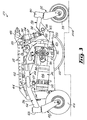
- FIG. 3 shows, in a reduced scale, wheelchair base 10 having the second drive wheel 22 raised on top of a ground elevation 104, thus an opposite movement of the second pivot arm assembly 26, here again, all six wheels 20, 22, 29, 31, 33 and 35 maintained in contact with the ground surface.
- pivot link 84 need not include a suspension element in some embodiments of the invention and that this suspension element is not necessarily solicited during dynamic articulations of the first pivot arm assembly 24 since its objective is mainly to absorb vibrations and sudden jolts caused by irregularities encountered by drive wheel 20 along the travel surface.
- the drive motor 86 is attached to the front pivot arm 56 and positioned forwardly of the first drive wheel 20. This configuration that the front end first auxiliary wheel 29 be positioned relatively far from the first drive wheel 20 so that the drive motor 86 can be attached between the first drive wheel 20 and the front end first auxiliary wheel 29. This increases the stability of the wheelchair base 10.
- Figure 5 illustrates an alternate embodiment 200 of the wheelchair base that is substantially similar to the wheelchair base 10, except for the configuration of the front and rear pivot arms 256 and 258 and the fact that the drive motor 86 is attached to the rear pivot arm 258, which allows for manufacturing a shorter front pivot arm 256 to increase the maneuverability of the wheelchair base 200.
- the wheelchair base 200 generally consists of a chassis 212, a battery compartment 214, mid-wheel power drive assembly 216 and first pivot arm assembly 222 provided with front and rear caster assemblies 228 and 232 respectively.
- Chassis 212 and battery compartment 214 are substantially equivalent to the ones in the first embodiment described above.
- the chassis 212 defines a base frame 211.
- a second pivot arm assembly (not seen in Fig. 5 ) substantially similar to the first pivot arm assembly 222 is provided.
- the first pivot arm assembly 222 includes a front pivot arm 256 and a rear pivot arm 258 pivotably coupled to one another through pivot interface 260.
- front pivot arm 256 has a substantially angular S-shaped configuration formed by a pair of elongated members 257a and 257b joined together through a cross-plate 257c.
- Lower elongated member 257a is terminated with a pivot support means 262a while upper elongated member 257b is terminated with a swivel assembly 268 that interfaces with front caster assembly 228.
- Rear pivot arm 258 generally defines a elongated member having a relatively more splayed S-shaped configuration than front pivot arm 256, with proximal end 259a terminated with a pivot support means 262b compatible with opposite pivot support means 262a, and angled distal end 259d terminated with a swivel assembly 280 and rear caster assembly 232.
- Rear pivot arm 258 is provided with rear pivot support means 282.
- the chassis 212 defines front and rear support means 244 and 248 for pivotally attaching thereto the front pivot arm 256 and a pivot link 284 that is also attached to the rear pivot support means 282.
- the front support means 244 extends generally downwardly from the base frame 211 and the rear support means extends generally parallel to the base frame 211.
- the mid-wheel power drive assembly 216 includes a drive motor 286, a gearbox unit 288 with a laterally extending drive axle 290 (shown with first drive wheel removed in FIG. 5 ).
- the gearbox unit 288 is rigidly attached to a face plate 257d on front pivot arm 256 through a substantially triangular adaptor bracket 292.
- proximal end of rear pivot arm 258 is axially aligned with proximal end of front pivot arm 256, as well as axially under mid-wheel power drive assembly 216, while the remainder of the rear pivot arm 258 form an outwardly lateral contour path to allow the main body of drive motor 286 to pivot in a vertical plane without interfering with rear pivot arm 258.
- the drive motor 286 is attached to the rear pivot arm 258.
- the general behavior of the present embodiment 200 of the motorized base, traveling on an uneven or irregular surface offers substantially the same characteristics and advantages as the first embodiment 10 described above. Namely the ability to preserve all wheels in contact with the uneven or irregular ground surface, with chassis 212 maintained in a substantially co-planar position relative to the average ground surface.
- a common characteristic to all the embodiments of the present invention described above are the substantially rectilinear alignment of the six wheels 20, 22, 29, 31, 33 and 35, on each side of wheelchair bases 10 and 200, which is achieved through the combination of the various structure configurations and angled portions of the front and rear pivot arms.
- front and rear pivot arms 56, 256 and 58, 258 are typically tubular members soldered or molded as individual single piece elements. All structural elements such as the chassis, battery compartment, pivot arms and mounting brackets are preferably made of a rigid and light material such as, for example, aluminum, a light steel alloy, carbon fibre or the like.
Landscapes
- Health & Medical Sciences (AREA)
- Life Sciences & Earth Sciences (AREA)
- Animal Behavior & Ethology (AREA)
- General Health & Medical Sciences (AREA)
- Public Health (AREA)
- Veterinary Medicine (AREA)
- Handcart (AREA)
Claims (15)
- Base de fauteuil roulant (10), ladite base de fauteuil roulant (10) étant utilisable avec des première et seconde roues d'entraînement (20, 22), des première et seconde roues auxiliaires (29, 31) de première extrémité et des première et seconde roues auxiliaires (33, 35) de seconde extrémité, ladite base de fauteuil roulant (10) comprenant :- un châssis de base (11) ;- un premier ensemble formant bras de pivot (24), ledit premier ensemble formant bras de pivot (24) incluant un premier bras de pivot de premier ensemble (56) et un second bras de pivot de premier ensemble (58), lesdits premier et second bras de pivot (56, 58) de premier ensemble étant accouplés de manière pivotante l'un à l'autre pour un mouvement pivotant autour d'un axe de pivot transversal (61) de premier ensemble, lesdits premier et second bras de pivot (56, 58) de premier ensemble définissant respectivement des première et seconde fixations de roue auxiliaire (68, 80) de premier ensemble sensiblement opposées audit axe de pivot transversal (61) de premier ensemble pour y fixer respectivement lesdites premières roues auxiliaires (29, 33) de première et seconde extrémités, ledit premier ensemble formant bras de pivot (24) incluant en outre une liaison de premier ensemble (84) couplée de manière pivotante audit second bras de pivot (58) de premier ensemble à un emplacement intermédiaire dudit axe de pivot transversal (61) de premier ensemble et de ladite seconde fixation de roue auxiliaire (80) de premier ensemble pour un mouvement pivotant autour d'un axe de liaison (85) de premier ensemble sensiblement parallèle audit axe de pivot transversal (61) de premier ensemble, ledit premier ensemble formant bras de pivot (24) définissant en outre une première fixation de roue d'entraînement (90) à un emplacement intermédiaire desdites première et seconde fixations de roue auxiliaire (68, 80) de premier ensemble pour y fixer ladite première roue d'entraînement (20) ; et- un second ensemble formant bras de pivot (26), ledit second ensemble formant bras de pivot (26) incluant un premier bras de pivot (56) de second ensemble et un second bras de pivot (58) de second ensemble, lesdits premier et second bras de pivot (56, 58) de second ensemble étant accouplés de manière pivotante l'un à l'autre pour un mouvement pivotant autour d'un axe de pivot transversal (61) de second ensemble, lesdits premier et second bras de pivot (56, 58) de second ensemble définissant respectivement des première et seconde fixations de roue auxiliaires (68, 80) de second ensemble sensiblement opposées audit axe de pivot transversal (61) de second ensemble pour y fixer respectivement lesdites secondes roues auxiliaires (31, 35) de première et seconde extrémités, ledit second ensemble formant bras de pivot (26) incluant en outre une liaison de second ensemble (84) couplée de manière pivotante audit second bras de pivot (58) de second ensemble à un emplacement intermédiaire dudit axe de pivot transversal (61) de second ensemble et de ladite seconde fixation de roue auxiliaire (80) de seconde ensemble pour un mouvement pivotant autour d'un axe de liaison (85) de second ensemble sensiblement parallèle audit axe de pivot transversal (61) de second ensemble, ledit second ensemble formant bras de pivot (26) définissant en outre une seconde fixation de roue d'entraînement (90) à un emplacement intermédiaire desdites première et seconde fixations de roue auxiliaire (68, 80) de second ensemble pour y fixer ladite seconde roue d'entraînement (22) ;- lesdits premier et second ensembles formant bras de pivot (24, 26) étant montés audit châssis de base (11) sensiblement latéralement opposés l'un à l'autre avec- lesdits axes de pivot transversaux (61) de premier et second ensembles étant sensiblement parallèles l'un à l'autre ;- lesdits premiers bras de pivot (56) de premier et second ensembles étant couplés de manière pivotante audit châssis de base (11) pour un mouvement pivotant respectivement autour d'un premier axe de bras (57) de premier et second ensembles, lesdits premiers axes de bras (57) de premier et second ensembles étant sensiblement parallèles audit axe de pivot transversal (61) de premier ensemble ; et- lesdites liaisons de premier et second ensembles (84) étant couplées de manière pivotante audit châssis de base (11) pour un mouvement pivotant respectivement autour d'un premier et d'un second axe de liaison-à-châssis d'ensemble (89), lesdits premier et second axes de liaison-à-châssis d'ensemble (89) étant sensiblement parallèles audit axe de pivot transversal (61) de premier ensemble ;- ledit premier ensemble formant bras de pivot (24) pouvant être pivoté par rapport audit châssis de base (11) indépendamment dudit second ensemble formant bras de pivot (24) ;- dans lequel ladite liaison de premier ensemble (84) définit une longueur de liaison de premier ensemble, ladite liaison de premier ensemble (84) incluant un élément de suspension pour permettre des variations de ladite longueur de liaison de premier ensemble.
- Base de fauteuil roulant (10) selon la revendication 1, dans laquelle ledit élément de suspension est configuré pour solliciter ladite liaison de premier ensemble (84) vers une longueur d'équilibre.
- Base de fauteuil roulant (10) selon la revendication 1, dans laquelle ledit élément de suspension lequel inclut une entretoise de suspension McPherson.
- Base de fauteuil roulant (10) selon la revendication 1, dans laquelle ledit premier ensemble formant bras de pivot (24) inclut en outre un élément de renfort de premier ensemble (97) couplé de manière opérationnelle audit second bras de pivot de premier ensemble (58) et audit châssis de base (11) pour permettre des mouvements pivotants de ladite liaison de premier ensemble (84) par rapport audit second bras de pivot de premier ensemble (58) et audit châssis de base (11).
- Base de fauteuil roulant (10) selon la revendication 4, dans laquelle ledit élément de renfort de premier ensemble (97) inclut- un premier organe d'élément de renfort (92) couplé de manière pivotante audit châssis de base (11) ; et- un second organe d'élément de renfort (94) couplé de manière pivotante audit second bras de pivot de premier ensemble (58) et audit premier organe d'élément de renfort (92).
- Base de fauteuil roulant (10) selon la revendication 5, dans laquelle ledit élément de renfort de premier ensemble (97) et ladite liaison de premier ensemble (84) sont couplés de manière pivotante audit châssis de base (11) dans une relation espacée l'un par rapport à l'autre et ledit élément de renfort de premier ensemble (97) et ladite liaison de premier ensemble (84) sont couplés de manière pivotante audit second bras de pivot de premier ensemble (58) dans une relation espacée l'un par rapport à l'autre.
- Base de fauteuil roulant (10) selon la revendication 1, ladite base de fauteuil roulant (10) étant utilisable avec un ensemble siège (55) monté audit châssis de base (11) par un utilisateur destiné (96) s'asseyant sur ledit ensemble siège (55), ladite base de fauteuil roulant (10) définissant une extrémité avant de base et une extrémité arrière de base, ledit second bras de pivot de premier ensemble (58) étant situé vers l'arrière par rapport audit premier bras de pivot de premier ensemble (56).
- Base de fauteuil roulant (10) selon la revendication 1, comprenant en outre un ensemble d'entraînement motorisé (16) couplé de manière opérationnelle à ladite fixation de première roue d'entraînement (90) pour faire tourner ladite première roue d'entraînement (20) par rapport audit châssis de base (11).
- Base de fauteuil roulant (10) selon la revendication 8, dans laquelle ledit ensemble d'entraînement motorisé (16) inclut un moteur d'entraînement (86) couplé de façon longitudinale à une unité de boîte de vitesses (88), ladite unité de boîte de vitesses (88) étant couplée à ladite fixation de première roue d'entraînement (90) pour faire tourner ladite première roue d'entraînement (20) par rapport à ladite base de fauteuil roulant (10).
- Base de fauteuil roulant (10) selon la revendication 9, dans laquelle ledit moteur d'entraînement (86) est attaché audit premier bras de pivot de premier ensemble (56).
- Base de fauteuil roulant (10) selon la revendication 9, dans laquelle ledit moteur d'entraînement (86) est attaché audit second bras de pivot de premier ensemble (58).
- Fauteuil roulant, ledit fauteuil roulant comprenant :- une base de fauteuil roulant selon n'importe laquelle des revendications 1 à 11 ;- des premières roues auxiliaires (29, 33) de première et seconde extrémité montées respectivement auxdits premier et second bras de pivot (56, 58) de premier ensemble sensiblement opposés audit axe de pivot transversal (61) de premier ensemble,- une première roue d'entraînement (20) montée audit premier ensemble formant bras de pivot (24) à un emplacement intermédiaire desdites premières roues auxiliaires (29, 33) de première et seconde extrémités ;- des secondes roues auxiliaires (31, 35) de première et seconde extrémités respectivement montées auxdits premier et second bras de pivot (56, 58) de second ensemble sensiblement opposés audit axe de pivot transversal (61) de second ensemble ; et- une seconde roue d'entraînement (22) montée audit second ensemble formant bras de pivot (26) à un emplacement intermédiaire desdites secondes roues auxiliaires (31, 35) de première et seconde extrémités.
- Fauteuil roulant selon la revendication 12, comprenant en outre un ensemble siège (55) monté sur ladite base de fauteuil roulant (10).
- Fauteuil roulant selon la revendication 13, comprenant en outre un ensemble d'entraînement motorisé (16) couplé de manière opérationnelle audit premier ensemble formant bras de pivot (24) et à ladite première roue d'entraînement (20) pour faire tourner ladite première roue d'entraînement (20) par rapport à ladite base de fauteuil roulant (10) pour propulser ledit fauteuil roulant.
- Fauteuil roulant selon la revendication 13, comprenant en outre un couple d'ensembles d'entraînement motorisés (16) chacun étant couplé de manière opérationnelle à un ensemble respectif desdits premier et second ensembles formant bras de pivot (24, 26) et à une roue respective desdites première et seconde roues d'entraînement (20, 22) pour faire tourner respectivement lesdites première et seconde roues d'entraînement (20, 22) par rapport à ladite base de fauteuil roulant (10) pour propulser ledit fauteuil roulant.
Applications Claiming Priority (2)
| Application Number | Priority Date | Filing Date | Title |
|---|---|---|---|
| GBGB0708834.7A GB0708834D0 (en) | 2007-05-08 | 2007-05-08 | Motorized base for a mid-wheel power drive wheelchair |
| PCT/CA2008/000899 WO2008134898A1 (fr) | 2007-05-08 | 2008-05-08 | Base pour chaise roulante |
Publications (3)
| Publication Number | Publication Date |
|---|---|
| EP2144584A1 EP2144584A1 (fr) | 2010-01-20 |
| EP2144584A4 EP2144584A4 (fr) | 2014-05-07 |
| EP2144584B1 true EP2144584B1 (fr) | 2015-08-26 |
Family
ID=38198889
Family Applications (1)
| Application Number | Title | Priority Date | Filing Date |
|---|---|---|---|
| EP08748298.0A Active EP2144584B1 (fr) | 2007-05-08 | 2008-05-08 | Base pour chaise roulante |
Country Status (5)
| Country | Link |
|---|---|
| US (1) | US8177257B2 (fr) |
| EP (1) | EP2144584B1 (fr) |
| CA (1) | CA2685829C (fr) |
| GB (1) | GB0708834D0 (fr) |
| WO (1) | WO2008134898A1 (fr) |
Families Citing this family (29)
| Publication number | Priority date | Publication date | Assignee | Title |
|---|---|---|---|---|
| US6554086B1 (en) | 2000-10-27 | 2003-04-29 | Invacare Corporation | Obstacle traversing wheelchair |
| US7040429B2 (en) * | 2001-10-10 | 2006-05-09 | Invacare Corporation | Wheelchair suspension |
| US7066290B2 (en) | 2001-10-19 | 2006-06-27 | Invacare Corp. | Wheelchair suspension having pivotal motor mount |
| US7293801B2 (en) | 2003-08-18 | 2007-11-13 | Invacare Corporation | Self-stabilizing suspension for wheeled vehicles |
| US11213441B2 (en) | 2002-10-25 | 2022-01-04 | Invacare Corporation | Suspension for wheeled vehicles |
| US7896394B2 (en) | 2005-08-18 | 2011-03-01 | Sunrise Medical Hhg, Inc. | Midwheel drive wheelchair with independent front and rear suspension |
| DK2277490T3 (en) | 2007-02-08 | 2015-04-13 | Invacare Corp | Wheelchair suspension |
| CA2676724C (fr) | 2007-02-14 | 2013-12-17 | Invacare Corporation | Systeme de commande de stabilite |
| GB2468272B (en) * | 2009-02-27 | 2011-03-23 | Karma Medical Prod Co Ltd | Chassis structure for mid-wheel drive power wheelchair |
| EP2485698B1 (fr) | 2009-10-09 | 2017-05-17 | Invacare Corporation | Suspension de fauteuil roulant |
| US8616309B2 (en) * | 2009-10-12 | 2013-12-31 | Pride Mobility Products Corporation | Wheelchair |
| DE102009051118B4 (de) * | 2009-10-13 | 2014-04-30 | Otto Bock Mobility Solutions Gmbh | Elektrorollstuhl |
| US20110253464A1 (en) * | 2010-04-15 | 2011-10-20 | Freerider Corp. | Suspension system for electric wheelchair |
| US8851214B2 (en) * | 2010-07-15 | 2014-10-07 | Permobil Ab | Electric mid-wheel drive wheelchair |
| AU2016225948B2 (en) * | 2010-12-02 | 2018-02-22 | Lendal Pty Ltd | Mobile Base |
| KR101215285B1 (ko) | 2010-12-28 | 2012-12-26 | 전자부품연구원 | 턱이 있는 보도에서도 주행이 가능한 전동 휠체어 |
| EP3260101B1 (fr) | 2011-07-06 | 2021-12-08 | Max Mobility, LLC | Système d'aide motorisée basé sur le mouvement pour fauteuils roulants |
| JP5821425B2 (ja) * | 2011-08-31 | 2015-11-24 | マツダ株式会社 | 車両の車体構造 |
| NZ628837A (en) | 2012-02-15 | 2016-10-28 | Invacare Corp | Wheelchair suspension |
| US9144525B2 (en) | 2013-03-14 | 2015-09-29 | Max Mobility, Llc. | Motion assistance system for wheelchairs |
| US8740240B1 (en) * | 2013-12-23 | 2014-06-03 | Maynard I. Merel | User-operated mobility apparatus |
| DK178212B1 (en) * | 2014-08-18 | 2015-08-24 | Roltec El Kørestole As | A power wheelchair and an assembly for aiding a power wheelchair in overcoming an obstacle |
| US9795524B2 (en) | 2015-02-24 | 2017-10-24 | Max Mobility, Llc | Assistive driving system for a wheelchair |
| CA3014158C (fr) * | 2016-02-12 | 2023-06-27 | Eugene Cherny | Dispositif d'assistance configurable |
| US10335330B2 (en) * | 2017-03-02 | 2019-07-02 | Travelsys4u Ltd. | Motor-driven chair steered by seat rotation |
| US10167051B1 (en) | 2017-12-12 | 2019-01-01 | Max Mobility, Llc | Assistive driving system for a wheelchair and method for controlling assistive driving system |
| US11903887B2 (en) | 2020-02-25 | 2024-02-20 | Invacare Corporation | Wheelchair and suspension systems |
| JP7628678B2 (ja) * | 2020-03-31 | 2025-02-12 | 国立大学法人 筑波大学 | 段差踏破機構を有する移動支援装置 |
| CN114028087B (zh) * | 2020-07-21 | 2025-11-21 | 常州中进医疗器材股份有限公司 | 一种防倾斜的轮椅 |
Family Cites Families (22)
| Publication number | Priority date | Publication date | Assignee | Title |
|---|---|---|---|---|
| GB1578742A (en) * | 1976-02-24 | 1980-11-12 | Nat Res Dev | Peripatetic vehicles |
| EP0740542B1 (fr) * | 1994-11-18 | 2005-02-02 | Degonda-Rehab S.A. | Siege roulant pour le transport ou l'assistance au deplacement d'au moins un utilisateur, notamment d'une personne handicapee |
| US6129165A (en) * | 1996-07-03 | 2000-10-10 | Pride Mobility Products, Corporation | Curb-climbing power wheelchair |
| NZ503425A (en) * | 1997-10-06 | 2001-09-28 | Invacare Corp | An articulating attachment of a seat to a chassis of a wheelchair which provides for enhanced shock absorption, control and stability |
| US6070898A (en) * | 1998-08-14 | 2000-06-06 | Sunrise Medical, Inc. | Suspension system for a wheelchair |
| US6460641B1 (en) * | 2000-06-29 | 2002-10-08 | Invacare Corporation | Mid-wheel drive wheelchair with front wheel multiple bias suspension and anti-tip assembly |
| US7040429B2 (en) | 2001-10-10 | 2006-05-09 | Invacare Corporation | Wheelchair suspension |
| US7066290B2 (en) * | 2001-10-19 | 2006-06-27 | Invacare Corp. | Wheelchair suspension having pivotal motor mount |
| US6923278B2 (en) * | 2002-05-06 | 2005-08-02 | Pride Mobility Products Corporation | Adjustable anti-tip wheels for power wheelchair |
| US7293801B2 (en) * | 2003-08-18 | 2007-11-13 | Invacare Corporation | Self-stabilizing suspension for wheeled vehicles |
| US7083195B2 (en) * | 2002-10-25 | 2006-08-01 | Invacare Corporation | Suspension with releasable locking system |
| CA2472816A1 (fr) * | 2003-06-30 | 2004-12-30 | Pride Mobility Products Corporation | Systeme de suspension pour fauteuil roulant motorise |
| US7234554B2 (en) * | 2003-07-02 | 2007-06-26 | Pride Mobility Products Corporation | Rear wheel drive power wheelchair |
| TWM244070U (en) * | 2003-08-13 | 2004-09-21 | Pihsiang Machinery Mfg Co Ltd | Suspending structure for a wheelchair |
| EP1522295A3 (fr) * | 2003-10-08 | 2005-04-20 | Pride Mobility Products, Corporation | Dispositif anti-basculement pour fauteuil roulant |
| US7316282B2 (en) * | 2003-10-08 | 2008-01-08 | Pride Mobility Products Corporation | Anti-tip system for wheelchairs |
| US7264272B2 (en) * | 2004-03-16 | 2007-09-04 | Pride Mobility Products Corporation | Bi-directional anti-tip system for powered wheelchairs |
| US7273118B2 (en) * | 2005-07-25 | 2007-09-25 | Shao-Shih Huang | Electric wheelchair frame |
| US7896394B2 (en) * | 2005-08-18 | 2011-03-01 | Sunrise Medical Hhg, Inc. | Midwheel drive wheelchair with independent front and rear suspension |
| EP1767178A1 (fr) | 2005-09-22 | 2007-03-28 | Kwang Yang Motor Co., Ltd. | Suspension de fauteuil roulant |
| WO2007047612A2 (fr) * | 2005-10-17 | 2007-04-26 | Pride Mobility Products Corporation | Fauteuil roulant electrique a compartiment batteries a acces lateral |
| CN2882586Y (zh) * | 2006-03-08 | 2007-03-28 | 唐承慧 | 一种新型中驱电动轮椅车的前后臂连接机构 |
-
2007
- 2007-05-08 GB GBGB0708834.7A patent/GB0708834D0/en not_active Ceased
-
2008
- 2008-05-08 EP EP08748298.0A patent/EP2144584B1/fr active Active
- 2008-05-08 US US12/599,182 patent/US8177257B2/en active Active
- 2008-05-08 CA CA2685829A patent/CA2685829C/fr active Active
- 2008-05-08 WO PCT/CA2008/000899 patent/WO2008134898A1/fr not_active Ceased
Also Published As
| Publication number | Publication date |
|---|---|
| US8177257B2 (en) | 2012-05-15 |
| EP2144584A1 (fr) | 2010-01-20 |
| CA2685829C (fr) | 2011-11-15 |
| EP2144584A4 (fr) | 2014-05-07 |
| WO2008134898A1 (fr) | 2008-11-13 |
| US20100301576A1 (en) | 2010-12-02 |
| CA2685829A1 (fr) | 2008-11-13 |
| GB0708834D0 (en) | 2007-06-13 |
| WO2008134898A8 (fr) | 2011-08-11 |
Similar Documents
| Publication | Publication Date | Title |
|---|---|---|
| EP2144584B1 (fr) | Base pour chaise roulante | |
| US6196343B1 (en) | Mid-wheel drive wheelchair | |
| US6601863B1 (en) | Mid-wheel drive wheelchair with rigid front wheel anti-tip stabilizer | |
| US8297388B2 (en) | Wheelchair with suspension arms | |
| EP3354247B1 (fr) | Bras oscillant pour fauteuil roulant à roues motrices centrales | |
| CA2304236C (fr) | Interface articulee siege/chassis pour un fauteuil roulant | |
| US4455031A (en) | Wheelchair | |
| US8925943B2 (en) | Wheelchair suspension | |
| US4310167A (en) | Center of gravity wheelchair with articulated chassis | |
| CA2340915C (fr) | Systeme de suspension pour fauteuil roulant | |
| US20060151982A1 (en) | Wheeled conveyance | |
| US20180008493A1 (en) | Swing arm linkage for a mid-wheel drive wheelchair | |
| US20240082084A1 (en) | Wheelchair and Suspension Systems | |
| US6672606B1 (en) | Suspension for personal mobility vehicle | |
| US7222881B1 (en) | Stop for an anti-tip wheel for a wheelchair | |
| EP2829258B1 (fr) | Structure de fauteuil roulant et ensemble de suspension | |
| GB2326138A (en) | Personal mobility vehicle | |
| AU753352B2 (en) | Improved mid-wheel drive wheelchair |
Legal Events
| Date | Code | Title | Description |
|---|---|---|---|
| PUAI | Public reference made under article 153(3) epc to a published international application that has entered the european phase |
Free format text: ORIGINAL CODE: 0009012 |
|
| 17P | Request for examination filed |
Effective date: 20091106 |
|
| AK | Designated contracting states |
Kind code of ref document: A1 Designated state(s): AT BE BG CH CY CZ DE DK EE ES FI FR GB GR HR HU IE IS IT LI LT LU LV MC MT NL NO PL PT RO SE SI SK TR |
|
| AX | Request for extension of the european patent |
Extension state: AL BA MK RS |
|
| DAX | Request for extension of the european patent (deleted) | ||
| A4 | Supplementary search report drawn up and despatched |
Effective date: 20140404 |
|
| RIC1 | Information provided on ipc code assigned before grant |
Ipc: A61G 5/10 20060101ALN20140331BHEP Ipc: A61G 5/04 20130101ALI20140331BHEP Ipc: A61G 5/06 20060101ALI20140331BHEP Ipc: A61G 5/00 20060101AFI20140331BHEP |
|
| RIC1 | Information provided on ipc code assigned before grant |
Ipc: A61G 5/10 20060101ALN20150218BHEP Ipc: A61G 5/00 20060101AFI20150218BHEP Ipc: A61G 5/04 20130101ALI20150218BHEP Ipc: A61G 5/06 20060101ALI20150218BHEP |
|
| GRAP | Despatch of communication of intention to grant a patent |
Free format text: ORIGINAL CODE: EPIDOSNIGR1 |
|
| INTG | Intention to grant announced |
Effective date: 20150402 |
|
| GRAS | Grant fee paid |
Free format text: ORIGINAL CODE: EPIDOSNIGR3 |
|
| GRAA | (expected) grant |
Free format text: ORIGINAL CODE: 0009210 |
|
| AK | Designated contracting states |
Kind code of ref document: B1 Designated state(s): AT BE BG CH CY CZ DE DK EE ES FI FR GB GR HR HU IE IS IT LI LT LU LV MC MT NL NO PL PT RO SE SI SK TR |
|
| REG | Reference to a national code |
Ref country code: GB Ref legal event code: FG4D |
|
| REG | Reference to a national code |
Ref country code: CH Ref legal event code: EP |
|
| REG | Reference to a national code |
Ref country code: AT Ref legal event code: REF Ref document number: 744722 Country of ref document: AT Kind code of ref document: T Effective date: 20150915 |
|
| REG | Reference to a national code |
Ref country code: IE Ref legal event code: FG4D |
|
| REG | Reference to a national code |
Ref country code: DE Ref legal event code: R096 Ref document number: 602008039801 Country of ref document: DE |
|
| REG | Reference to a national code |
Ref country code: NL Ref legal event code: FP |
|
| REG | Reference to a national code |
Ref country code: AT Ref legal event code: MK05 Ref document number: 744722 Country of ref document: AT Kind code of ref document: T Effective date: 20150826 |
|
| REG | Reference to a national code |
Ref country code: LT Ref legal event code: MG4D |
|
| PG25 | Lapsed in a contracting state [announced via postgrant information from national office to epo] |
Ref country code: NO Free format text: LAPSE BECAUSE OF FAILURE TO SUBMIT A TRANSLATION OF THE DESCRIPTION OR TO PAY THE FEE WITHIN THE PRESCRIBED TIME-LIMIT Effective date: 20151126 Ref country code: LV Free format text: LAPSE BECAUSE OF FAILURE TO SUBMIT A TRANSLATION OF THE DESCRIPTION OR TO PAY THE FEE WITHIN THE PRESCRIBED TIME-LIMIT Effective date: 20150826 Ref country code: GR Free format text: LAPSE BECAUSE OF FAILURE TO SUBMIT A TRANSLATION OF THE DESCRIPTION OR TO PAY THE FEE WITHIN THE PRESCRIBED TIME-LIMIT Effective date: 20151127 Ref country code: FI Free format text: LAPSE BECAUSE OF FAILURE TO SUBMIT A TRANSLATION OF THE DESCRIPTION OR TO PAY THE FEE WITHIN THE PRESCRIBED TIME-LIMIT Effective date: 20150826 Ref country code: LT Free format text: LAPSE BECAUSE OF FAILURE TO SUBMIT A TRANSLATION OF THE DESCRIPTION OR TO PAY THE FEE WITHIN THE PRESCRIBED TIME-LIMIT Effective date: 20150826 |
|
| PG25 | Lapsed in a contracting state [announced via postgrant information from national office to epo] |
Ref country code: IS Free format text: LAPSE BECAUSE OF FAILURE TO SUBMIT A TRANSLATION OF THE DESCRIPTION OR TO PAY THE FEE WITHIN THE PRESCRIBED TIME-LIMIT Effective date: 20151226 Ref country code: AT Free format text: LAPSE BECAUSE OF FAILURE TO SUBMIT A TRANSLATION OF THE DESCRIPTION OR TO PAY THE FEE WITHIN THE PRESCRIBED TIME-LIMIT Effective date: 20150826 Ref country code: ES Free format text: LAPSE BECAUSE OF FAILURE TO SUBMIT A TRANSLATION OF THE DESCRIPTION OR TO PAY THE FEE WITHIN THE PRESCRIBED TIME-LIMIT Effective date: 20150826 Ref country code: PT Free format text: LAPSE BECAUSE OF FAILURE TO SUBMIT A TRANSLATION OF THE DESCRIPTION OR TO PAY THE FEE WITHIN THE PRESCRIBED TIME-LIMIT Effective date: 20151228 Ref country code: SE Free format text: LAPSE BECAUSE OF FAILURE TO SUBMIT A TRANSLATION OF THE DESCRIPTION OR TO PAY THE FEE WITHIN THE PRESCRIBED TIME-LIMIT Effective date: 20150826 Ref country code: PL Free format text: LAPSE BECAUSE OF FAILURE TO SUBMIT A TRANSLATION OF THE DESCRIPTION OR TO PAY THE FEE WITHIN THE PRESCRIBED TIME-LIMIT Effective date: 20150826 Ref country code: HR Free format text: LAPSE BECAUSE OF FAILURE TO SUBMIT A TRANSLATION OF THE DESCRIPTION OR TO PAY THE FEE WITHIN THE PRESCRIBED TIME-LIMIT Effective date: 20150826 |
|
| REG | Reference to a national code |
Ref country code: CH Ref legal event code: NV Representative=s name: FIAMMENGHI-FIAMMENGHI, CH |
|
| PG25 | Lapsed in a contracting state [announced via postgrant information from national office to epo] |
Ref country code: IT Free format text: LAPSE BECAUSE OF FAILURE TO SUBMIT A TRANSLATION OF THE DESCRIPTION OR TO PAY THE FEE WITHIN THE PRESCRIBED TIME-LIMIT Effective date: 20150826 Ref country code: CZ Free format text: LAPSE BECAUSE OF FAILURE TO SUBMIT A TRANSLATION OF THE DESCRIPTION OR TO PAY THE FEE WITHIN THE PRESCRIBED TIME-LIMIT Effective date: 20150826 Ref country code: SK Free format text: LAPSE BECAUSE OF FAILURE TO SUBMIT A TRANSLATION OF THE DESCRIPTION OR TO PAY THE FEE WITHIN THE PRESCRIBED TIME-LIMIT Effective date: 20150826 Ref country code: EE Free format text: LAPSE BECAUSE OF FAILURE TO SUBMIT A TRANSLATION OF THE DESCRIPTION OR TO PAY THE FEE WITHIN THE PRESCRIBED TIME-LIMIT Effective date: 20150826 Ref country code: DK Free format text: LAPSE BECAUSE OF FAILURE TO SUBMIT A TRANSLATION OF THE DESCRIPTION OR TO PAY THE FEE WITHIN THE PRESCRIBED TIME-LIMIT Effective date: 20150826 |
|
| REG | Reference to a national code |
Ref country code: FR Ref legal event code: PLFP Year of fee payment: 9 |
|
| REG | Reference to a national code |
Ref country code: DE Ref legal event code: R097 Ref document number: 602008039801 Country of ref document: DE |
|
| PG25 | Lapsed in a contracting state [announced via postgrant information from national office to epo] |
Ref country code: RO Free format text: LAPSE BECAUSE OF FAILURE TO SUBMIT A TRANSLATION OF THE DESCRIPTION OR TO PAY THE FEE WITHIN THE PRESCRIBED TIME-LIMIT Effective date: 20150826 |
|
| PLBE | No opposition filed within time limit |
Free format text: ORIGINAL CODE: 0009261 |
|
| STAA | Information on the status of an ep patent application or granted ep patent |
Free format text: STATUS: NO OPPOSITION FILED WITHIN TIME LIMIT |
|
| 26N | No opposition filed |
Effective date: 20160530 |
|
| PG25 | Lapsed in a contracting state [announced via postgrant information from national office to epo] |
Ref country code: BE Free format text: LAPSE BECAUSE OF NON-PAYMENT OF DUE FEES Effective date: 20160531 Ref country code: SI Free format text: LAPSE BECAUSE OF FAILURE TO SUBMIT A TRANSLATION OF THE DESCRIPTION OR TO PAY THE FEE WITHIN THE PRESCRIBED TIME-LIMIT Effective date: 20150826 |
|
| PG25 | Lapsed in a contracting state [announced via postgrant information from national office to epo] |
Ref country code: LU Free format text: LAPSE BECAUSE OF FAILURE TO SUBMIT A TRANSLATION OF THE DESCRIPTION OR TO PAY THE FEE WITHIN THE PRESCRIBED TIME-LIMIT Effective date: 20160508 Ref country code: BE Free format text: LAPSE BECAUSE OF FAILURE TO SUBMIT A TRANSLATION OF THE DESCRIPTION OR TO PAY THE FEE WITHIN THE PRESCRIBED TIME-LIMIT Effective date: 20150826 |
|
| REG | Reference to a national code |
Ref country code: IE Ref legal event code: MM4A |
|
| REG | Reference to a national code |
Ref country code: FR Ref legal event code: PLFP Year of fee payment: 10 |
|
| PG25 | Lapsed in a contracting state [announced via postgrant information from national office to epo] |
Ref country code: IE Free format text: LAPSE BECAUSE OF NON-PAYMENT OF DUE FEES Effective date: 20160508 |
|
| PG25 | Lapsed in a contracting state [announced via postgrant information from national office to epo] |
Ref country code: HU Free format text: LAPSE BECAUSE OF FAILURE TO SUBMIT A TRANSLATION OF THE DESCRIPTION OR TO PAY THE FEE WITHIN THE PRESCRIBED TIME-LIMIT; INVALID AB INITIO Effective date: 20080508 Ref country code: CY Free format text: LAPSE BECAUSE OF FAILURE TO SUBMIT A TRANSLATION OF THE DESCRIPTION OR TO PAY THE FEE WITHIN THE PRESCRIBED TIME-LIMIT Effective date: 20150826 |
|
| REG | Reference to a national code |
Ref country code: FR Ref legal event code: PLFP Year of fee payment: 11 |
|
| PG25 | Lapsed in a contracting state [announced via postgrant information from national office to epo] |
Ref country code: MC Free format text: LAPSE BECAUSE OF FAILURE TO SUBMIT A TRANSLATION OF THE DESCRIPTION OR TO PAY THE FEE WITHIN THE PRESCRIBED TIME-LIMIT Effective date: 20150826 Ref country code: MT Free format text: LAPSE BECAUSE OF NON-PAYMENT OF DUE FEES Effective date: 20160531 Ref country code: TR Free format text: LAPSE BECAUSE OF FAILURE TO SUBMIT A TRANSLATION OF THE DESCRIPTION OR TO PAY THE FEE WITHIN THE PRESCRIBED TIME-LIMIT Effective date: 20150826 |
|
| PG25 | Lapsed in a contracting state [announced via postgrant information from national office to epo] |
Ref country code: BG Free format text: LAPSE BECAUSE OF FAILURE TO SUBMIT A TRANSLATION OF THE DESCRIPTION OR TO PAY THE FEE WITHIN THE PRESCRIBED TIME-LIMIT Effective date: 20150826 |
|
| PGFP | Annual fee paid to national office [announced via postgrant information from national office to epo] |
Ref country code: NL Payment date: 20210512 Year of fee payment: 14 |
|
| PGFP | Annual fee paid to national office [announced via postgrant information from national office to epo] |
Ref country code: CH Payment date: 20210513 Year of fee payment: 14 |
|
| REG | Reference to a national code |
Ref country code: CH Ref legal event code: PL |
|
| REG | Reference to a national code |
Ref country code: NL Ref legal event code: MM Effective date: 20220601 |
|
| PG25 | Lapsed in a contracting state [announced via postgrant information from national office to epo] |
Ref country code: LI Free format text: LAPSE BECAUSE OF NON-PAYMENT OF DUE FEES Effective date: 20220531 Ref country code: CH Free format text: LAPSE BECAUSE OF NON-PAYMENT OF DUE FEES Effective date: 20220531 |
|
| PG25 | Lapsed in a contracting state [announced via postgrant information from national office to epo] |
Ref country code: NL Free format text: LAPSE BECAUSE OF NON-PAYMENT OF DUE FEES Effective date: 20220601 |
|
| PGFP | Annual fee paid to national office [announced via postgrant information from national office to epo] |
Ref country code: DE Payment date: 20250528 Year of fee payment: 18 |
|
| PGFP | Annual fee paid to national office [announced via postgrant information from national office to epo] |
Ref country code: GB Payment date: 20250402 Year of fee payment: 18 |
|
| PGFP | Annual fee paid to national office [announced via postgrant information from national office to epo] |
Ref country code: FR Payment date: 20250527 Year of fee payment: 18 |