EP2144782B1 - Vorrichtung zur montage eines motorfahrzeugsitzes - Google Patents
Vorrichtung zur montage eines motorfahrzeugsitzes Download PDFInfo
- Publication number
- EP2144782B1 EP2144782B1 EP08788155A EP08788155A EP2144782B1 EP 2144782 B1 EP2144782 B1 EP 2144782B1 EP 08788155 A EP08788155 A EP 08788155A EP 08788155 A EP08788155 A EP 08788155A EP 2144782 B1 EP2144782 B1 EP 2144782B1
- Authority
- EP
- European Patent Office
- Prior art keywords
- mounting
- structural
- structural element
- mounting device
- elements
- Prior art date
- Legal status (The legal status is an assumption and is not a legal conclusion. Google has not performed a legal analysis and makes no representation as to the accuracy of the status listed.)
- Ceased
Links
Images
Classifications
-
- B—PERFORMING OPERATIONS; TRANSPORTING
- B60—VEHICLES IN GENERAL
- B60N—SEATS SPECIALLY ADAPTED FOR VEHICLES; VEHICLE PASSENGER ACCOMMODATION NOT OTHERWISE PROVIDED FOR
- B60N2/00—Seats specially adapted for vehicles; Arrangement or mounting of seats in vehicles
- B60N2/005—Arrangement or mounting of seats in vehicles, e.g. dismountable auxiliary seats
- B60N2/015—Attaching seats directly to vehicle chassis
Definitions
- the present invention relates to a seat fastening device, and more particularly the seats of a motor vehicle.
- a seat is mounted on the vehicle structural elements, and housings are disposed between the structural element and the seat. These housings carry first fixing means adapted to cooperate fastening means carried by the seat.
- the seat must be positioned differently in at least the vertical direction, to obtain the desired livability.
- the differences in height are taken into account by the insertion of specific parts integral with the seats.
- adding specific sheet metal parts to each height value has a strong impact on costs and investments, and balances the savings from using a common seat.
- One of the objectives of the invention is therefore to allow to fix a seat at different heights without adding specific parts to each height, whether in the seats or in the vehicle structure.
- the present invention is also inexpensive and compact.
- the invention proposes a seat fixing device of the type comprising a fastening element adapted to be fixed on a first and a second structural element, this fastening element carrying first seat fixing means, characterized in that the fastening element has guide elements slidable with respect to the two structural elements, so that the fastening element is slidable between a first and a second lower position relative to the two structural elements, and in that these guide elements have dimensions and shapes determined so that these guide elements can be welded to the first and second structural element, when the first fastening element is in the first position high, or in the second lower position, or in an intermediate position between the first and second sition.
- the invention also relates to a motor vehicle comprising a fixing device as described above, in which the first and the second structural elements are perpendicular, the second structural element extending substantially longitudinally on one of the sides of the vehicle. or in the center of the vehicle.
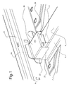
- a fastening element 2 is positioned between structural elements 4, 8 of the vehicle and the seat to be fixed, not shown in the figures. It will be understood that only one fastening element 2 is described and shown below, but that a plurality of fastening elements according to the invention can be associated with the same seat.
- the fixing element 2 is fixed on a first structural element 4 and on a second structural element 8 extending perpendicularly to the first structural element 4.
- the fastening element 2 can be welded to the structural elements.
- the first structural element 4 is a cross member extending substantially transversely to the vehicle and the second structural element 8 is a flap, longitudinal structure extending on one side of the vehicle.
- the second structural element is the tunnel, a longitudinal structure extending in the center of the vehicle.
- the fixing element 2 is in the form of a hollow housing, in which a first horizontal support face 20 is extended at two opposite ends by two transverse faces 22, each transverse face 22 being substantially perpendicular to the first support face 20 and extending this support face 20 downwards.
- At least one rabbet 24, and advantageously three as shown in FIG. figure 1 extends a free edge of the support face 20 located between the two transverse faces 22, while the opposite free edge is extended by a longitudinal face which forms a guide lug 26 substantially perpendicular to the first support surface 20 and which extends the support face 20 downwards.
- the fastening element 2 has the shape of a hollow body whose end facing the second structural element 8 is provided with fastening rabbets 24. These fastening rabbets 24 are able to be pressed against the internal face 9 of the second structural element 8, to allow the welding of the fastening element 2 on the second structural element 8.
- the fastening element 2 is furthermore fixed on the first structural element 4.
- the transverse faces 22 of the fastening element 2 have a vertical dimension sufficient to be pressed against the transverse walls 5 of the first element of the structure. structure 4.
- the longitudinal face of the fastening element 2 opposite to the fastening rabbets 24 forms a guide lug 26 which cooperates with a support means 6 formed in the first structural element 4.
- This means of support 6, which has the shape of an edge falling from the first support face 20, can be obtained by way of example by punching in this first support face and then by folding this punched portion.
- the guide lug 26 can thus slide against the support means 6, through the first support face 20.
- the guide lug 26 is fixed on the support means 6, and for example welded.
- first attachment means 28 of the seat adapted to cooperate with second fastening means carried by the seat.
- first respectively second fixing means may be a rail and slide assembly allowing the securing the seat and its longitudinal sliding relative to the vehicle structure.
- the fastening element 2 makes it possible to arrange the first fastening means 28 of the seat at a predetermined height before welding the fastening element 2 on the structural elements of the vehicle.
- the fixing element 2 has guiding elements able to allow the fastening element 2 to slide relative to at least the first structural element 4.
- the guide elements are formed in particular by the transverse faces 22 of the fastening element 2, which have a parallelism between them, so that these transverse faces 22 can slide along the parallel transverse walls 5 forming the first structural element 4 During this sliding, the guide lug 26 formed on the fixing element 2 slides along the support means 6 formed in the first structural element 4.
- the displacement of the fastening element 2 relative to the first structure element 4 is blocked according to the longitudinal component by the cooperation of the transverse faces 22 and the transverse walls 5.
- the cooperation of the guide tab and the support means on the one hand, and fastening rabbets 24 and the internal face 9 of the second structural element 8 on the other hand blocks the displacement of the fastening element 2 relative to the first structural element 4 according to the transv component ersale. This is why the inner face 9, the fastening rabbets 24, the guide lug 26 and the support means 6 are all substantially vertical and parallel.
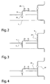
- the fastening element 2 can thus slide vertically along the first 4 and second 8 structural element , between a first position high, represented in figure 2 and in which seats can be mounted on this fastener in an elevated position, and a second low position, shown in FIG. figure 4 and in which seats can be mounted on this fastener in a more sporty position.
- the dimension of the guide elements is adapted to allow fixing of the fastening element 2 on the first structural element 4 regardless of the position of the sliding.
- FIG 2 at least a part of the guide elements is always in contact with the first and the second structural element, and in particular the lower part of the transverse faces 22 is in contact with the corresponding transverse walls 5 of the first structural element 4, and the lower part of the longitudinal face forming the guide lug 26 is in contact with the bearing means 6.
- the attachment of the fastening element 2 can thus be done in the upper position by welding 30 of the transverse faces 22 on the first element of structure 4, and by welding 30 fastening rabbets 24 on the second structural element 8, the dimension of these rabbets 24 being such that they remain in contact with the internal face 9 of this second structural element 8 even in positron high.
Landscapes
- Engineering & Computer Science (AREA)
- Aviation & Aerospace Engineering (AREA)
- Transportation (AREA)
- Mechanical Engineering (AREA)
- Seats For Vehicles (AREA)
- Lock And Its Accessories (AREA)
- Automobile Manufacture Line, Endless Track Vehicle, Trailer (AREA)
Claims (10)
- Vorrichtung zur Befestigung eines Sitzes eines Kraftfahrzeugs der Art, die ein Befestigungselement (2) umfasst, das geeignet ist, an einem ersten (4) und einem zweiten (8) Strukturelement befestigt zu sein, wobei dieses Befestigungselement (2) erste Sitzbefestigungsmittel (28) trägt, dadurch gekennzeichnet, dass das Befestigungselement (2) Führungselemente aufweist, die geeignet sind, bezüglich der zwei Strukturelemente (4, 8) so zu gleiten, dass das Befestigungselement (2) geeignet ist, zwischen einer hohen ersten Position und einer niedrigen zweiten Position bezüglich der Strukturelemente zu gleiten,
und dass diese Führungselemente Abmessungen und Formen haben, die so bestimmt sind, dass diese Führungselemente an das erste und das zweite Strukturelement (4, 8) geschweißt werden können, wenn das Befestigungselement (2) in der hohen ersten Position ist oder in der niedrigen zweiten Position oder in einer Position zwischen der ersten und der zweiten Position ist. - Befestigungsvorrichtung nach Anspruch 1, dadurch gekennzeichnet, dass die Führungselemente des Befestigungselements (2) aus mindestens zwei Querflächen (22) gebildet sind, deren Form und Ausrichtung das Gleiten entlang von Querwänden (5) gestatten, die das erste Strukturelement (4) bilden.
- Befestigungsvorrichtung nach Anspruch 2, dadurch gekennzeichnet, dass die beiden Querflächen (22) und die Querwände (5) vertikal sind.
- Befestigungsvorrichtung nach Anspruch 2 oder 3, dadurch gekennzeichnet, dass die Führungselemente außerdem aus einem Führungsansatz (26) gebildet sind, der geeignet ist, gegen ein Stützmittel (6) zu gleiten, das im ersten Strukturelement (4) gebildet ist.
- Befestigungsvorrichtung nach dem vorhergehenden Anspruch, dadurch gekennzeichnet, dass die vertikale Abmessung des Führungsansatzes (26) geringer als die vertikale Abmessung der Querflächen (22) ist.
- Befestigungsvorrichtung nach Anspruch 4 oder 5, dadurch gekennzeichnet, dass das Befestigungselement (2) derart ist, dass der Führungsansatz (26) im Wesentlichen senkrecht zu den Querflächen (22) verläuft.
- Befestigungsvorrichtung nach einem der vorhergehenden Ansprüche, dadurch gekennzeichnet, dass die Führungselemente außerdem durch Falze (24) gebildet sind, die an einem Ende des Befestigungselements (2) ausgebildet und geeignet sind, entlang einer inneren Fläche (9) des zweiten Strukturelements (8) zu gleiten.
- Befestigungsvorrichtung nach dem vorhergehenden Anspruch, dadurch gekennzeichnet, dass das Befestigungselement (2) derart ist, dass die Falze (24) im Wesentlichen senkrecht zu den Querflächen (22) verlaufen.
- Kraftfahrzeug mit einer Befestigungsvorrichtung nach einem der Ansprüche 1 bis 8, dadurch gekennzeichnet, dass das erste (4) und das zweite (8) Strukturelement senkrecht sind, wobei sich das zweite Strukturelement (8) im Wesentlichen in Längsrichtung an einer der Seiten des Fahrzeugs erstreckt.
- Kraftfahrzeug mit einer Befestigungsvorrichtung nach einem der Ansprüche 1 bis 8, dadurch gekennzeichnet, dass das erste (4) und das zweite (8) Strukturelement senkrecht sind, wobei sich das zweite Strukturelement (8) im Wesentlichen in Längsrichtung zur Mitte des Fahrzeugs erstreckt.
Applications Claiming Priority (2)
| Application Number | Priority Date | Filing Date | Title |
|---|---|---|---|
| FR0755066A FR2916168B1 (fr) | 2007-05-14 | 2007-05-14 | Dispositif de fixation de siege d'un vehicule automobile |
| PCT/FR2008/050633 WO2008142329A2 (fr) | 2007-05-14 | 2008-04-10 | Dispositif de fixation de siege d'un vehicule automobile |
Publications (2)
| Publication Number | Publication Date |
|---|---|
| EP2144782A2 EP2144782A2 (de) | 2010-01-20 |
| EP2144782B1 true EP2144782B1 (de) | 2010-12-01 |
Family
ID=38922716
Family Applications (1)
| Application Number | Title | Priority Date | Filing Date |
|---|---|---|---|
| EP08788155A Ceased EP2144782B1 (de) | 2007-05-14 | 2008-04-10 | Vorrichtung zur montage eines motorfahrzeugsitzes |
Country Status (5)
| Country | Link |
|---|---|
| EP (1) | EP2144782B1 (de) |
| AT (1) | ATE490116T1 (de) |
| DE (1) | DE602008003787D1 (de) |
| FR (1) | FR2916168B1 (de) |
| WO (1) | WO2008142329A2 (de) |
Family Cites Families (2)
| Publication number | Priority date | Publication date | Assignee | Title |
|---|---|---|---|---|
| IT1193127B (it) * | 1983-01-18 | 1988-06-02 | Fiat Auto Spa | Dispositivo di supporto per un sedile e procedimento per eseguire il montaggio del sedile munito di tale dispositivo su un veicolo |
| JP2005219521A (ja) * | 2004-02-03 | 2005-08-18 | Toyota Motor Corp | 車体下部構造 |
-
2007
- 2007-05-14 FR FR0755066A patent/FR2916168B1/fr not_active Expired - Fee Related
-
2008
- 2008-04-10 EP EP08788155A patent/EP2144782B1/de not_active Ceased
- 2008-04-10 AT AT08788155T patent/ATE490116T1/de not_active IP Right Cessation
- 2008-04-10 DE DE602008003787T patent/DE602008003787D1/de active Active
- 2008-04-10 WO PCT/FR2008/050633 patent/WO2008142329A2/fr not_active Ceased
Also Published As
| Publication number | Publication date |
|---|---|
| WO2008142329A2 (fr) | 2008-11-27 |
| WO2008142329A3 (fr) | 2009-05-22 |
| FR2916168A1 (fr) | 2008-11-21 |
| EP2144782A2 (de) | 2010-01-20 |
| ATE490116T1 (de) | 2010-12-15 |
| FR2916168B1 (fr) | 2009-07-03 |
| DE602008003787D1 (de) | 2011-01-13 |
Similar Documents
| Publication | Publication Date | Title |
|---|---|---|
| EP2144782B1 (de) | Vorrichtung zur montage eines motorfahrzeugsitzes | |
| EP3789246A1 (de) | Vorrichtung zum verstauen mit schubladen für ein kraftfahrzeug | |
| EP1882608A2 (de) | Autokindersitz, der Führungsvorrichtungen für einen Bauchgurt umfasst | |
| EP4313636A1 (de) | Vorrichtung zur begrenzung der bewegung eines fahrzeugstossdämpfers, insbesondere eines kraftfahrzeugstossdämpfers | |
| EP1742826B1 (de) | Frontstruktur eines kraftfahrzeuges | |
| EP1681223A1 (de) | Positionsblockiereinrichtung einer verstellbaren Kraftfahrzeuglenksäule, Anordnung mit einer solchen Einrichtung und Kraftfahrzeug mit einer solchen Anordnung | |
| FR2789456A1 (fr) | Agencement pour la fixation rapide d'une glissiere sur un plancher de vehicule automobile | |
| EP2470412B1 (de) | Element zur befestigung einer armaturenbrettverstrebung an einem bauteil, im besonderen für ein kraftfahrzeug | |
| EP1207094A1 (de) | Verkleidungsschale für den oberen Teil der Lenksäule | |
| EP1819543B1 (de) | Türplattenversteifer | |
| EP2572962B1 (de) | Befestigungseinheit für Lenksäule | |
| EP3064412B1 (de) | Herstellungsverfahren einer fahrerkabine eines schienenfahrzeugs, insbesondere für strassenbahn | |
| FR3133807A1 (fr) | Ensemble de porte avec pièce de support et pièce supérieure assemblées | |
| FR3126956A1 (fr) | Élément de structure formant une traverse arrière de pavillon et une traverse de toit. | |
| FR2871535A1 (fr) | Agencement de fixation d'un element de vehicule automobile | |
| EP1584516A1 (de) | Einheit zum Montieren einer Dachreeling auf einem Fahrzeugdach | |
| FR2975347A1 (fr) | Vehicule automobile a portiere coulissante | |
| FR2932764A1 (fr) | Traverse arriere de pavillon de vehicule | |
| WO2009030557A1 (fr) | Absorbeur de choc pour vehicules automobiles et dispositif comportant un tel absorbeur | |
| FR3103748A1 (fr) | Element de plancher arriere de vehicule automobile | |
| FR2789453A1 (fr) | Agencement perfectionne pour la fixation d'une glissiere sur un plancher de vehicule automobile | |
| FR3059925B1 (fr) | Procede de positionnement d'une console centrale au moyen d'un outil de positionnement et outil correspondant | |
| EP4008609A1 (de) | Anordnung für eine karosserie eines kraftfahrzeugs und indexierungsvorrichtung für eine solche anordnung | |
| FR2864494A1 (fr) | Plancher de vehicule comprenant des logements de fixation pour des organes de ceinture de securite | |
| FR3041316A1 (fr) | Structure de caisse d'un vehicule automobile comprenant un renfort de parclose. |
Legal Events
| Date | Code | Title | Description |
|---|---|---|---|
| PUAI | Public reference made under article 153(3) epc to a published international application that has entered the european phase |
Free format text: ORIGINAL CODE: 0009012 |
|
| 17P | Request for examination filed |
Effective date: 20091103 |
|
| AK | Designated contracting states |
Kind code of ref document: A2 Designated state(s): AT BE BG CH CY CZ DE DK EE ES FI FR GB GR HR HU IE IS IT LI LT LU LV MC MT NL NO PL PT RO SE SI SK TR |
|
| AX | Request for extension of the european patent |
Extension state: AL BA MK RS |
|
| GRAP | Despatch of communication of intention to grant a patent |
Free format text: ORIGINAL CODE: EPIDOSNIGR1 |
|
| GRAS | Grant fee paid |
Free format text: ORIGINAL CODE: EPIDOSNIGR3 |
|
| GRAA | (expected) grant |
Free format text: ORIGINAL CODE: 0009210 |
|
| AK | Designated contracting states |
Kind code of ref document: B1 Designated state(s): AT BE BG CH CY CZ DE DK EE ES FI FR GB GR HR HU IE IS IT LI LT LU LV MC MT NL NO PL PT RO SE SI SK TR |
|
| REG | Reference to a national code |
Ref country code: GB Ref legal event code: FG4D Free format text: NOT ENGLISH |
|
| REG | Reference to a national code |
Ref country code: CH Ref legal event code: EP |
|
| REG | Reference to a national code |
Ref country code: IE Ref legal event code: FG4D |
|
| REF | Corresponds to: |
Ref document number: 602008003787 Country of ref document: DE Date of ref document: 20110113 Kind code of ref document: P |
|
| REG | Reference to a national code |
Ref country code: NL Ref legal event code: VDEP Effective date: 20101201 |
|
| PG25 | Lapsed in a contracting state [announced via postgrant information from national office to epo] |
Ref country code: LT Free format text: LAPSE BECAUSE OF FAILURE TO SUBMIT A TRANSLATION OF THE DESCRIPTION OR TO PAY THE FEE WITHIN THE PRESCRIBED TIME-LIMIT Effective date: 20101201 Ref country code: NO Free format text: LAPSE BECAUSE OF FAILURE TO SUBMIT A TRANSLATION OF THE DESCRIPTION OR TO PAY THE FEE WITHIN THE PRESCRIBED TIME-LIMIT Effective date: 20110301 |
|
| LTIE | Lt: invalidation of european patent or patent extension |
Effective date: 20101201 |
|
| PG25 | Lapsed in a contracting state [announced via postgrant information from national office to epo] |
Ref country code: SE Free format text: LAPSE BECAUSE OF FAILURE TO SUBMIT A TRANSLATION OF THE DESCRIPTION OR TO PAY THE FEE WITHIN THE PRESCRIBED TIME-LIMIT Effective date: 20101201 Ref country code: LV Free format text: LAPSE BECAUSE OF FAILURE TO SUBMIT A TRANSLATION OF THE DESCRIPTION OR TO PAY THE FEE WITHIN THE PRESCRIBED TIME-LIMIT Effective date: 20101201 Ref country code: BG Free format text: LAPSE BECAUSE OF FAILURE TO SUBMIT A TRANSLATION OF THE DESCRIPTION OR TO PAY THE FEE WITHIN THE PRESCRIBED TIME-LIMIT Effective date: 20110301 Ref country code: SI Free format text: LAPSE BECAUSE OF FAILURE TO SUBMIT A TRANSLATION OF THE DESCRIPTION OR TO PAY THE FEE WITHIN THE PRESCRIBED TIME-LIMIT Effective date: 20101201 Ref country code: NL Free format text: LAPSE BECAUSE OF FAILURE TO SUBMIT A TRANSLATION OF THE DESCRIPTION OR TO PAY THE FEE WITHIN THE PRESCRIBED TIME-LIMIT Effective date: 20101201 Ref country code: HR Free format text: LAPSE BECAUSE OF FAILURE TO SUBMIT A TRANSLATION OF THE DESCRIPTION OR TO PAY THE FEE WITHIN THE PRESCRIBED TIME-LIMIT Effective date: 20101201 Ref country code: CY Free format text: LAPSE BECAUSE OF FAILURE TO SUBMIT A TRANSLATION OF THE DESCRIPTION OR TO PAY THE FEE WITHIN THE PRESCRIBED TIME-LIMIT Effective date: 20101201 Ref country code: FI Free format text: LAPSE BECAUSE OF FAILURE TO SUBMIT A TRANSLATION OF THE DESCRIPTION OR TO PAY THE FEE WITHIN THE PRESCRIBED TIME-LIMIT Effective date: 20101201 Ref country code: AT Free format text: LAPSE BECAUSE OF FAILURE TO SUBMIT A TRANSLATION OF THE DESCRIPTION OR TO PAY THE FEE WITHIN THE PRESCRIBED TIME-LIMIT Effective date: 20101201 |
|
| REG | Reference to a national code |
Ref country code: IE Ref legal event code: FD4D |
|
| PG25 | Lapsed in a contracting state [announced via postgrant information from national office to epo] |
Ref country code: GR Free format text: LAPSE BECAUSE OF FAILURE TO SUBMIT A TRANSLATION OF THE DESCRIPTION OR TO PAY THE FEE WITHIN THE PRESCRIBED TIME-LIMIT Effective date: 20110302 |
|
| PG25 | Lapsed in a contracting state [announced via postgrant information from national office to epo] |
Ref country code: CZ Free format text: LAPSE BECAUSE OF FAILURE TO SUBMIT A TRANSLATION OF THE DESCRIPTION OR TO PAY THE FEE WITHIN THE PRESCRIBED TIME-LIMIT Effective date: 20101201 Ref country code: ES Free format text: LAPSE BECAUSE OF FAILURE TO SUBMIT A TRANSLATION OF THE DESCRIPTION OR TO PAY THE FEE WITHIN THE PRESCRIBED TIME-LIMIT Effective date: 20110312 Ref country code: EE Free format text: LAPSE BECAUSE OF FAILURE TO SUBMIT A TRANSLATION OF THE DESCRIPTION OR TO PAY THE FEE WITHIN THE PRESCRIBED TIME-LIMIT Effective date: 20101201 Ref country code: IS Free format text: LAPSE BECAUSE OF FAILURE TO SUBMIT A TRANSLATION OF THE DESCRIPTION OR TO PAY THE FEE WITHIN THE PRESCRIBED TIME-LIMIT Effective date: 20110401 Ref country code: PT Free format text: LAPSE BECAUSE OF FAILURE TO SUBMIT A TRANSLATION OF THE DESCRIPTION OR TO PAY THE FEE WITHIN THE PRESCRIBED TIME-LIMIT Effective date: 20110401 Ref country code: IE Free format text: LAPSE BECAUSE OF FAILURE TO SUBMIT A TRANSLATION OF THE DESCRIPTION OR TO PAY THE FEE WITHIN THE PRESCRIBED TIME-LIMIT Effective date: 20101201 |
|
| PG25 | Lapsed in a contracting state [announced via postgrant information from national office to epo] |
Ref country code: PL Free format text: LAPSE BECAUSE OF FAILURE TO SUBMIT A TRANSLATION OF THE DESCRIPTION OR TO PAY THE FEE WITHIN THE PRESCRIBED TIME-LIMIT Effective date: 20101201 Ref country code: RO Free format text: LAPSE BECAUSE OF FAILURE TO SUBMIT A TRANSLATION OF THE DESCRIPTION OR TO PAY THE FEE WITHIN THE PRESCRIBED TIME-LIMIT Effective date: 20101201 Ref country code: SK Free format text: LAPSE BECAUSE OF FAILURE TO SUBMIT A TRANSLATION OF THE DESCRIPTION OR TO PAY THE FEE WITHIN THE PRESCRIBED TIME-LIMIT Effective date: 20101201 |
|
| PLBE | No opposition filed within time limit |
Free format text: ORIGINAL CODE: 0009261 |
|
| STAA | Information on the status of an ep patent application or granted ep patent |
Free format text: STATUS: NO OPPOSITION FILED WITHIN TIME LIMIT |
|
| BERE | Be: lapsed |
Owner name: RENAULT S.A.S. Effective date: 20110430 |
|
| PG25 | Lapsed in a contracting state [announced via postgrant information from national office to epo] |
Ref country code: DK Free format text: LAPSE BECAUSE OF FAILURE TO SUBMIT A TRANSLATION OF THE DESCRIPTION OR TO PAY THE FEE WITHIN THE PRESCRIBED TIME-LIMIT Effective date: 20101201 |
|
| 26N | No opposition filed |
Effective date: 20110902 |
|
| PG25 | Lapsed in a contracting state [announced via postgrant information from national office to epo] |
Ref country code: MC Free format text: LAPSE BECAUSE OF NON-PAYMENT OF DUE FEES Effective date: 20110430 |
|
| REG | Reference to a national code |
Ref country code: DE Ref legal event code: R097 Ref document number: 602008003787 Country of ref document: DE Effective date: 20110902 |
|
| PG25 | Lapsed in a contracting state [announced via postgrant information from national office to epo] |
Ref country code: MT Free format text: LAPSE BECAUSE OF FAILURE TO SUBMIT A TRANSLATION OF THE DESCRIPTION OR TO PAY THE FEE WITHIN THE PRESCRIBED TIME-LIMIT Effective date: 20101201 |
|
| PG25 | Lapsed in a contracting state [announced via postgrant information from national office to epo] |
Ref country code: BE Free format text: LAPSE BECAUSE OF NON-PAYMENT OF DUE FEES Effective date: 20110430 |
|
| REG | Reference to a national code |
Ref country code: CH Ref legal event code: PL |
|
| PG25 | Lapsed in a contracting state [announced via postgrant information from national office to epo] |
Ref country code: CH Free format text: LAPSE BECAUSE OF NON-PAYMENT OF DUE FEES Effective date: 20120430 Ref country code: LI Free format text: LAPSE BECAUSE OF NON-PAYMENT OF DUE FEES Effective date: 20120430 |
|
| PG25 | Lapsed in a contracting state [announced via postgrant information from national office to epo] |
Ref country code: LU Free format text: LAPSE BECAUSE OF NON-PAYMENT OF DUE FEES Effective date: 20110410 |
|
| PG25 | Lapsed in a contracting state [announced via postgrant information from national office to epo] |
Ref country code: TR Free format text: LAPSE BECAUSE OF FAILURE TO SUBMIT A TRANSLATION OF THE DESCRIPTION OR TO PAY THE FEE WITHIN THE PRESCRIBED TIME-LIMIT Effective date: 20101201 |
|
| PG25 | Lapsed in a contracting state [announced via postgrant information from national office to epo] |
Ref country code: HU Free format text: LAPSE BECAUSE OF FAILURE TO SUBMIT A TRANSLATION OF THE DESCRIPTION OR TO PAY THE FEE WITHIN THE PRESCRIBED TIME-LIMIT Effective date: 20101201 |
|
| REG | Reference to a national code |
Ref country code: FR Ref legal event code: PLFP Year of fee payment: 8 |
|
| REG | Reference to a national code |
Ref country code: FR Ref legal event code: PLFP Year of fee payment: 9 |
|
| REG | Reference to a national code |
Ref country code: FR Ref legal event code: PLFP Year of fee payment: 10 |
|
| REG | Reference to a national code |
Ref country code: FR Ref legal event code: PLFP Year of fee payment: 11 |
|
| PGFP | Annual fee paid to national office [announced via postgrant information from national office to epo] |
Ref country code: IT Payment date: 20220420 Year of fee payment: 15 Ref country code: GB Payment date: 20220425 Year of fee payment: 15 Ref country code: FR Payment date: 20220421 Year of fee payment: 15 Ref country code: DE Payment date: 20220420 Year of fee payment: 15 |
|
| REG | Reference to a national code |
Ref country code: DE Ref legal event code: R119 Ref document number: 602008003787 Country of ref document: DE |
|
| GBPC | Gb: european patent ceased through non-payment of renewal fee |
Effective date: 20230410 |
|
| PG25 | Lapsed in a contracting state [announced via postgrant information from national office to epo] |
Ref country code: GB Free format text: LAPSE BECAUSE OF NON-PAYMENT OF DUE FEES Effective date: 20230410 |
|
| PG25 | Lapsed in a contracting state [announced via postgrant information from national office to epo] |
Ref country code: GB Free format text: LAPSE BECAUSE OF NON-PAYMENT OF DUE FEES Effective date: 20230410 Ref country code: FR Free format text: LAPSE BECAUSE OF NON-PAYMENT OF DUE FEES Effective date: 20230430 Ref country code: DE Free format text: LAPSE BECAUSE OF NON-PAYMENT OF DUE FEES Effective date: 20231103 |
|
| PG25 | Lapsed in a contracting state [announced via postgrant information from national office to epo] |
Ref country code: IT Free format text: LAPSE BECAUSE OF NON-PAYMENT OF DUE FEES Effective date: 20230410 |