EP2144807B1 - Ensemble de raccordement de deux nervures courbees d'un aeronef ou d'un engin spatial - Google Patents
Ensemble de raccordement de deux nervures courbees d'un aeronef ou d'un engin spatial Download PDFInfo
- Publication number
- EP2144807B1 EP2144807B1 EP08749997A EP08749997A EP2144807B1 EP 2144807 B1 EP2144807 B1 EP 2144807B1 EP 08749997 A EP08749997 A EP 08749997A EP 08749997 A EP08749997 A EP 08749997A EP 2144807 B1 EP2144807 B1 EP 2144807B1
- Authority
- EP
- European Patent Office
- Prior art keywords
- sections
- coupling element
- coupling
- ribs
- aircraft
- Prior art date
- Legal status (The legal status is an assumption and is not a legal conclusion. Google has not performed a legal analysis and makes no representation as to the accuracy of the status listed.)
- Active
Links
Images



Classifications
-
- B—PERFORMING OPERATIONS; TRANSPORTING
- B64—AIRCRAFT; AVIATION; COSMONAUTICS
- B64C—AEROPLANES; HELICOPTERS
- B64C1/00—Fuselages; Constructional features common to fuselages, wings, stabilising surfaces or the like
- B64C1/06—Frames; Stringers; Longerons ; Fuselage sections
- B64C1/061—Frames
Definitions
- This invention relates to a connecting arrangement of two curved ribs of an aircraft or spacecraft.
- Such connecting arrangements are used for connecting curved ribs in aircraft and spacecraft, particularly in the spherical fuselage region.
- a rib plane which runs perpendicularly to the longitudinal axis of an aircraft, for example, two or even a plurality of rib parts are connected together to form an entire rib according to the radius of the fuselage in this plane.
- Fig. 5 shows another representation of a connecting device known to the applicant for connecting two curved ribs 1 and 2.
- a longitudinal axis of the associated aircraft or spacecraft, not shown, on one inner side 4, is perpendicular to the drawing plane.
- Each of the ribs has an inner edge with an inner belt 14, which has an inner radius R1, R2.
- rib 1, 2 expands over its rib height H1, H2 as far as the start of its outer belt 13.
- Outer belt 13 has recesses through which run stringers 10, 11.
- An outer skin 12 of the aircraft or spacecraft is provided on outer belt 13.
- Both ribs 1, 2 are each provided with a connecting section V1, V2 in a connecting region 16 at each of their ends, in which section is installed a coupling element 5, by means of fastening elements 8, which element enables the two ribs 1, 2 to be connected.
- Coupling element 5 is designed on its lower edge with the same contour which inner belts 14 of ribs 1, 2 have.
- a further significant disadvantage consists in the fact that a new coupling element, adapted to the inner radius, must be produced for every modified inner contour.
- the object of the present invention is to provide a connecting arrangement which removes or significantly reduces the above-mentioned disadvantages.
- a connecting arrangement for connecting two curved ribs of an aircraft of spacecraft with a coupling element which can be connected by predetermined coupling sections to respective connecting sections of the two ribs, wherein at least the predetermined coupling sections of the coupling element are of a rectilinear design, and wherein at least the respective connecting sections of the two ribs have rectilinearly running inner belt regions for each rectilinear connection of the predetermined coupling sections of the coupling element.
- This invention therefore has the advantage that the connecting arrangement is designed with rectilinear connecting sections of the ribs to be connected with a straight, easily produced and hence favourable coupling element, which reduces the associated production and straightening costs considerably.
- the same geometries of the coupling unit can be used in different fuselage positions of an aircraft or spacecraft.
- each rectilinearly running inner belt region of the connecting sections into the contour of each inner belt with an inner radius to have a transition radius.
- a relatively large radius for example greater or equal to 1000 mm, is selected as the transition radius. Consequently stress concentrations in the ribs and coupling elements are advantageously avoided.
- the rectilinearly running inner belt can be constructed in the connecting sections so that it is designed as a section of a tangent of an arc of a connecting radius, which section has a radius which is smaller by a certain value than the value of the inner radii of the ribs to be connected.
- this tangent runs at right angles to a perpendicular which runs in the centre of the connecting sections perpendicularly through an outer skin of the aircraft or spacecraft. It is particularly advantageous for this determined value to be the same for all devices for connecting curved ribs present in an aircraft or spacecraft. Therefore a rectilinear simple coupling element can be used several times for this purpose, even if the inner radii are varied, thereby considerably reducing the multiplicity of parts.
- the coupling elements can be formed from sections of an extruded profile that are cut to length or are cut to length and machined. Such an extruded profile is easy to cut to length and is obtainable in many versions, for example in fatigue resistant alloys. This eliminates the disadvantages of plate coupling elements with a constant thickness, for the advantage of the extruded profiles to be dimensioned thus lies in the fact that they do not have to be milled in terms of thickness and shape.
- the coupling element is also possible to design the coupling element as a simple plate edge part of constant thickness.
- the coupling element in an alternative aspect provision is made for the coupling element to be designed as a milled part, or for it to consist of a combination of a cut to length part and a machined part, thereby increasing its scope of application.
- Fig. 1 sows a partial view of an exemplary embodiment of an inventive connecting device of two curved ribs 1, 2 of an aircraft or spacecraft.
- Both ribs 1, 2 each have an inner belt 14 with an inner radius R1, R2.
- both inner radii R1, R2 are essentially of the same size.
- Ribs 1, 2 are connected by means of a coupling element 5 at their ends in a connecting region 10, wherein the ends of ribs 1, 2 are arranged opposite each other at a certain distance. This gap thus formed is covered by coupling element 5.
- Connecting region 10 lies in the region of two stringers 9 and 11 and has a connecting region length V, which is divided into two connecting sections VI and V2.
- this connecting region V the contour of inner belt 14 of both ribs 1, 2 is formed so that it runs rectilinearly in an inner belt region 15.
- Coupling element 5 which is explained in more detail later, is fastened in connecting sections V1, V2 to ribs 1, 2 by means of fastening elements 8, rivets for example, with coupling surfaces 6, 7 (see Fig. 3 ), and therefore forms a connection between the two ribs 1, 2.
- Coupling element 5 has a lower edge which is designed so that it runs rectilinearly corresponding to the rectilinear inner belt region 15.
- transition radius RU is selected with a value of approximately 1000 mm or greater. This is a value determined by tests carried out by the applicant.
- the rib height geometry in connecting region 10 is established centrally between two stringers 9, 11 (half stringer distance SA) at right angles to inner belt region 15 at a height dimension H.
- a perpendicular N is erected at the point of intersection I of half stringer distance 1 ⁇ 2 SA with outer skin 12, on which height dimension H is removed at this point of intersection I towards inner side 4.
- a straight line G is constructed at right angles to the perpendicular. This straight line G forms the basis of the rectilinear course of inner contour region 15 of connecting region 10.
- Straight line G is at the same time tangential to a connecting radius RV at point of intersection II.
- a value is selected which is dimensioned so that it is the same size for all the inner rib radii used in an aircraft or spacecraft.
- the advantage of this is that the same geometries can be used in all rib connecting devices, regardless of the inner radii, as a result of which all coupling elements 5 can have the same geometries.
- Height difference HD is also the value by which connecting radius RV is smaller than inner radius R1, R2.
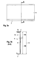
- Fig. 3a represents an exemplary coupling element 5 in a side view and Fig. 3 represents a section through coupling element 5 along line A-A in Fig. 3b .
- Coupling element 5 is shown in side view in Fig. 3a in a simple rectangular design.
- the transverse sides may also have a different shape, as shown for example in Figs. 1 and 2 .
- Coupling element 5 is formed in this example with an L-shaped cross-section which corresponds to connecting sections V1, V2 of ribs 1, 2, as shown in Fig. 3b .
- a coupling region 6 of coupling element 5 forms a long leg of the L-shaped cross-section and has the height dimension HB.
- This coupling surface 6 serves as the connection to the rib at height H1, H2.
- a second coupling surface 7 forms the short leg of the L-shaped cross-section of coupling element 5 and is formed rectilinearly in the longitudinal direction corresponding to the rectilinear inner belt region 15 of connecting sections V1, V2 of ribs 1, 2. This means that a longitudinal axis of coupling surface 7 runs parallel to a longitudinal axis of coupling surface 6, both coupling surfaces 6 and 7 being at right angles to each other.
- This shape of coupling element 5 is simple to cut to length, for example from an extruded profile. Additional machining for shaping the transverse sides is possible by milling cutting or the like. However, machining of the upper longitudinal edge, so that it runs at an angle and not parallel to the longitudinal axis of coupling surface 7, is also conceivable for producing the shape shown in Fig. 4 . In this case the initial shape of coupling element 5 may have a simple rectangular cross-section.
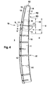
- Fig. 4 shows a partial view of a second exemplary aspect of an inventive device for connecting two curved ribs 1, 2.
- Inner radii R1, R2 of both ribs are in this case of different sizes, inner radius R2 being smaller than R1.
- the respective rectilinearly running inner belt regions 15 of connecting sections V1, V2 are sections of a tangent of the larger arc section of the arc sections with inner radii R1, R2.
- perpendicular N is also erected at point of intersection I on outer skin 12, as described in Fig. 2 .
- a tangent is placed on the arc section with the larger inner radius of inner radii R1 and R2 (here R1), which in the connecting device shown in Fig. 4 intersects with perpendicular N at a point of intersection III and with the arc section with the smaller inner radius R2.
- the distance between the two points of intersection I and II on perpendicular Ni is a dimension which has the same composition as height dimension H (see Fig. 2 ), but the value may be different for a height difference.
- the direction of the tangent i.e. of rectilinear inner contour region 15, can therefore be established.
- this tangent does not intersect at right angles with perpendicular N at point of intersection III but at a certain angle ⁇ .
- a resultant point of intersection IV of this tangent with the arc section with the smaller inner radius R2 is rounded out with transition radius RV.
- this tangent forms the rectilinearly running inner belt region 15 of connecting sections V1, V2. It is also possible to select this tangent so that it is at the same time the tangent on both arc sections.
- the invention is not limited to the exemplary embodiment described above.
- coupling element 5 it is also conceivable for coupling element 5 to be connected on both sides in connecting region 10.
- Coupling element 5 may be a bent plate part, which is particularly advantageous in the second exemplary aspect Moreover, a bent plate part can be easily produced, to particular advantage, because of the rectilinearity.
Landscapes
- Engineering & Computer Science (AREA)
- Mechanical Engineering (AREA)
- Aviation & Aerospace Engineering (AREA)
- Moulding By Coating Moulds (AREA)
- Connection Of Plates (AREA)
- Lining Or Joining Of Plastics Or The Like (AREA)
- Handcart (AREA)
- Replacement Of Web Rolls (AREA)
- Package Frames And Binding Bands (AREA)
- Cable Accessories (AREA)
Claims (8)
- Ensemble de raccordement comprenant un élément d'accouplement (5) et deux nervures courbées (1, 2) d'un aéronef ou d'un engin spatial, l'élément d'accouplement (5) pouvant être raccordé au moyen de sections d'accouplement prédéterminées (6, 7) aux sections d'accouplement respectives (V1, V2) des deux nervures (1, 2), caractérisé en ce que au moins les sections d'accouplement prédéterminées (6, 7) de l'élément d'accouplement (5) sont conçues de façon rectiligne ; et en ce que au moins les sections d'accouplement respectives (V1, V2) des deux nervures (1, 2) présentent chacune des zones de ceinture intérieure (15) s'étendant de façon rectiligne pour un raccordement rectiligne respectif des sections d'accouplement prédéterminées (6, 7) de l'élément d'accouplement (5) .
- Ensemble de raccordement selon la revendication 1, caractérisé en ce qu'une transition de chacune des zones de ceinture intérieure s'étendant de façon rectiligne (15) des sections d'accouplement (V1, V2) dans le contour d'une ceinture intérieure respective (14) présentant un rayon intérieur (R1, R2) possède un rayon de transition (RU).
- Ensemble de raccordement selon la revendication 2, caractérisé en ce que dans le cas des nervures courbées (1, 2) à raccorder, qui possèdent des ceintures intérieures respectives (14) présentant des rayons intérieurs (R1, R2) de différentes dimensions, les zones de ceinture intérieure respectives s'étendant de façon rectiligne (15) des sections d'accouplement (V1, V2) forment des sections d'une tangente de la plus grande section d'arc des sections d'arc avec les rayons intérieurs (R1, R2) des ceintures intérieures (14), la tangente s'étendant à un angle (α) par rapport à une perpendiculaire (N) passant approximativement au centre des sections d'accouplement (V1, V2) en traversant perpendiculairement une enveloppe extérieure (12) de l'aéronef ou l'engin spatial.
- Ensemble de raccordement selon la revendication 2, caractérisé en ce que dans le cas des nervures courbées (1, 2) à raccorder, qui possèdent des ceintures intérieures respectives (14) présentant des rayons intérieurs (R1, R2) de même dimension, les zones de ceinture intérieure respectives s'étendant de façon rectiligne (15) des sections d'accouplement (V1, V2) forment des sections d'une tangente d'une section d'arc avec un rayon d'accouplement (RV) qui est plus petit d'une valeur prédéfinie (HD) que la valeur des rayons intérieurs (R1, R2), cette tangente s'étendant à angles droits par rapport à une perpendiculaire (N) passant au centre des sections d'accouplement (V1, V2) en traversant perpendiculairement une enveloppe extérieure (12) de l'aéronef ou l'engin spatial.
- Ensemble de raccordement selon la revendication 4, caractérisé en ce que la valeur (HD) est de la même dimension dans tous les ensembles de raccordement permettant de raccorder les nervures courbées (1, 2) présentes dans un aéronef ou un engin spatial.
- Ensemble de raccordement selon au moins une des revendications précédentes, caractérisé en ce que les sections d'accouplement prédéterminées (6, 7) conçues de façon rectiligne de l'élément d'accouplement (5) possèdent des surfaces qui s'étendent de façon sensiblement perpendiculaire les unes par rapport aux autres ou à un certain angle les unes par rapport aux autres.
- Ensemble de raccordement selon au moins une des revendications précédentes, caractérisé en ce que l'élément d'accouplement (5) est formé à partir de sections d'un profilé extrudé qui ont été coupées à longueur et/ou usinées.
- Ensemble de raccordement selon au moins une des revendications précédentes, caractérisé en ce que l'élément d'accouplement (5) est conçu sous la forme d'une pièce laminée.
Applications Claiming Priority (3)
| Application Number | Priority Date | Filing Date | Title |
|---|---|---|---|
| US92771707P | 2007-05-04 | 2007-05-04 | |
| DE102007021075A DE102007021075B4 (de) | 2007-05-04 | 2007-05-04 | Verbindungsanordnung zum Verbinden zweier gekrümmter Spanten eines Luft- oder Raumfahrzeugs |
| PCT/EP2008/055428 WO2008135533A1 (fr) | 2007-05-04 | 2008-05-02 | Dispositif de raccordement pour relier deux nervures courbées d'un aéronef ou d'un engin spatial |
Publications (2)
| Publication Number | Publication Date |
|---|---|
| EP2144807A1 EP2144807A1 (fr) | 2010-01-20 |
| EP2144807B1 true EP2144807B1 (fr) | 2010-10-13 |
Family
ID=39809668
Family Applications (1)
| Application Number | Title | Priority Date | Filing Date |
|---|---|---|---|
| EP08749997A Active EP2144807B1 (fr) | 2007-05-04 | 2008-05-02 | Ensemble de raccordement de deux nervures courbees d'un aeronef ou d'un engin spatial |
Country Status (10)
| Country | Link |
|---|---|
| US (1) | US8540190B2 (fr) |
| EP (1) | EP2144807B1 (fr) |
| JP (1) | JP5113243B2 (fr) |
| CN (1) | CN101678889B (fr) |
| AT (1) | ATE484448T1 (fr) |
| BR (1) | BRPI0810787A2 (fr) |
| CA (1) | CA2685188A1 (fr) |
| DE (2) | DE102007021075B4 (fr) |
| RU (1) | RU2507112C2 (fr) |
| WO (1) | WO2008135533A1 (fr) |
Families Citing this family (4)
| Publication number | Priority date | Publication date | Assignee | Title |
|---|---|---|---|---|
| GB8608055D0 (en) | 1986-04-02 | 1986-05-08 | Shell Int Research | Fire resistant plastic pipe |
| US8356771B2 (en) * | 2008-07-21 | 2013-01-22 | Airbus Operations Gmbh | Coupling for joining two frame segments |
| DE102019211434B3 (de) * | 2019-07-31 | 2020-11-05 | Premium Aerotec Gmbh | Spantkomponente und verfahren zur herstellung einer spantkomponente, spant und rumpfstruktur für ein luftfahrzeug |
| WO2021186718A1 (fr) * | 2020-03-19 | 2021-09-23 | 三菱重工業株式会社 | Corps de support et procédé de montage de corps de support |
Family Cites Families (15)
| Publication number | Priority date | Publication date | Assignee | Title |
|---|---|---|---|---|
| US1803494A (en) * | 1928-12-20 | 1931-05-05 | Emboutissage Et De Const Mecan | Hollow-frame assembly |
| US1766961A (en) * | 1929-09-25 | 1930-06-24 | Arthur B Steuart | Fuselage frame |
| GB368367A (en) | 1929-12-27 | 1932-03-01 | Budd Edward G Mfg Co | Improvements in trusses particularly for use in aircraft structures |
| US1885406A (en) * | 1930-06-20 | 1932-11-01 | Avions Kellner Bechereau Sa | Manufacture of hollow bodies |
| US1922063A (en) * | 1931-05-01 | 1933-08-15 | Curtiss Aeroplane & Motor Co | Monocoque body |
| US5560102A (en) * | 1992-10-13 | 1996-10-01 | The Boeing Company | Panel and fuselage assembly |
| US5518208A (en) * | 1993-12-28 | 1996-05-21 | The Boeing Company | Optimum aircraft body frame to body skin shear tie installation pattern for body skin/stringer circumferential splices |
| CN1051520C (zh) * | 1996-10-07 | 2000-04-19 | 王新云 | 飞行器的预应力结构及制造方法 |
| RU2123965C1 (ru) * | 1997-01-28 | 1998-12-27 | Государственное акционерное общество "Ташкентское авиационное производственное объединение им.В.П.Чкалова" | Способ сборки объемных агрегатов летательных аппаратов |
| DE19924909C1 (de) * | 1999-05-31 | 2000-06-21 | Daimler Chrysler Ag | Metallisches Schalenbauteil |
| DE04714198T8 (de) * | 2003-02-24 | 2007-06-06 | Bell Helicopter Textron, Inc., Fort Worth | Kontaktversteifer für konstruktionshaut |
| DE10314039A1 (de) * | 2003-03-28 | 2004-10-07 | Airbus Deutschland Gmbh | Spantbauteil für ein Flugzeug |
| US7252267B2 (en) * | 2003-10-17 | 2007-08-07 | The Boeing Company | Aircraft archway architecture |
| FR2906008B1 (fr) * | 2006-09-15 | 2008-11-07 | Airbus France Sa | Eclisse de lisses et dispositif de jonction orbitale |
| FR2910874B1 (fr) * | 2007-01-02 | 2009-02-13 | Airbus France Sas | Lisses assemblees au niveau d'une jonction circonferentielle d'un fuselage d'avion. |
-
2007
- 2007-05-04 DE DE102007021075A patent/DE102007021075B4/de not_active Expired - Fee Related
-
2008
- 2008-05-02 AT AT08749997T patent/ATE484448T1/de not_active IP Right Cessation
- 2008-05-02 EP EP08749997A patent/EP2144807B1/fr active Active
- 2008-05-02 CA CA002685188A patent/CA2685188A1/fr not_active Abandoned
- 2008-05-02 WO PCT/EP2008/055428 patent/WO2008135533A1/fr not_active Ceased
- 2008-05-02 RU RU2009142874/11A patent/RU2507112C2/ru not_active IP Right Cessation
- 2008-05-02 CN CN200880014191XA patent/CN101678889B/zh not_active Expired - Fee Related
- 2008-05-02 DE DE602008003025T patent/DE602008003025D1/de active Active
- 2008-05-02 BR BRPI0810787-4A2A patent/BRPI0810787A2/pt not_active IP Right Cessation
- 2008-05-02 JP JP2010504751A patent/JP5113243B2/ja not_active Expired - Fee Related
- 2008-05-02 US US12/597,027 patent/US8540190B2/en not_active Expired - Fee Related
Also Published As
| Publication number | Publication date |
|---|---|
| CN101678889A (zh) | 2010-03-24 |
| JP2010525977A (ja) | 2010-07-29 |
| WO2008135533A1 (fr) | 2008-11-13 |
| JP5113243B2 (ja) | 2013-01-09 |
| EP2144807A1 (fr) | 2010-01-20 |
| US8540190B2 (en) | 2013-09-24 |
| US20100148009A1 (en) | 2010-06-17 |
| CA2685188A1 (fr) | 2008-11-13 |
| DE102007021075A1 (de) | 2008-11-06 |
| RU2009142874A (ru) | 2011-06-10 |
| BRPI0810787A2 (pt) | 2014-10-29 |
| ATE484448T1 (de) | 2010-10-15 |
| DE102007021075B4 (de) | 2012-06-28 |
| DE602008003025D1 (de) | 2010-11-25 |
| CN101678889B (zh) | 2013-09-04 |
| RU2507112C2 (ru) | 2014-02-20 |
Similar Documents
| Publication | Publication Date | Title |
|---|---|---|
| EP1809430A2 (fr) | Procede permettant de former des structures de regulation de courbure dans une feuille de materiau, feuille obtenue et logements de matrices a cet effet | |
| US8540190B2 (en) | Connecting arrangement comprising a coupling element and two curved ribs of an aircraft or spacecraft | |
| DE4435538C2 (de) | Verfahren zur Herstellung eines Flachsiebes | |
| DE102014104084A1 (de) | System zur elastischen mittelnden Ausrichtung, Verfahren zum Herstellen desselben und Schneidstempel dafür | |
| US20110293383A1 (en) | Indexable insert | |
| JP2009525184A (ja) | 鋭いエッジ有し、かつ、だれを低減した単段式設備における部材の精密打抜き方法及びその装置 | |
| JP2001219316A (ja) | 本体と目打ちしていない歯を備えた鋸刃 | |
| DE102011107789A1 (de) | Schneideinsatz, insbesondere für Zahnradfräser | |
| CN110799280B (zh) | 金属板的切断方法、金属成形体的制造方法以及金属成形体 | |
| JP2019075371A (ja) | 面取り縁部を有する屈曲した電気コンタクト要素およびその製造方法 | |
| US6810712B2 (en) | Split die and die nib defined by the same | |
| EP3263838A1 (fr) | Pale de turbine avec canal de refroidissement interne | |
| US20110232097A1 (en) | Electric shaver | |
| US6351979B1 (en) | Extrusion die | |
| CN106998922B (zh) | 座椅用垫 | |
| JP5205499B2 (ja) | 蒸気タービン用静翼の製造法 | |
| CN101827984B (zh) | 用于轻质结构构件的支撑结构 | |
| CN101283195B (zh) | 链接片、包含该链接片的链以及通过该链构成的链传动装置和装备有该链传动装置的车辆 | |
| RU2337774C2 (ru) | Штамп для равноканального углового прессования (варианты) | |
| CN112934970A (zh) | 热轧中间坯斜锲压接剪刃装置 | |
| KR20190113627A (ko) | 프레스 금형의 펀치 구조, 프레스 금형, 프레스 성형품의 제조방법 및 프레스 성형품 | |
| DE10033465B4 (de) | Turbinenleitrad und Verfahren zur Herstellung eines Turbinenleitrades | |
| SE528625C2 (sv) | Stanskniv | |
| EP1745919B1 (fr) | Moule pour former le profil d'un pneumatique pour véhicule. | |
| US20080308703A1 (en) | Adjusting Device for a Motor Vehicle Seat |
Legal Events
| Date | Code | Title | Description |
|---|---|---|---|
| PUAI | Public reference made under article 153(3) epc to a published international application that has entered the european phase |
Free format text: ORIGINAL CODE: 0009012 |
|
| 17P | Request for examination filed |
Effective date: 20091105 |
|
| AK | Designated contracting states |
Kind code of ref document: A1 Designated state(s): AT BE BG CH CY CZ DE DK EE ES FI FR GB GR HR HU IE IS IT LI LT LU LV MC MT NL NO PL PT RO SE SI SK TR |
|
| AX | Request for extension of the european patent |
Extension state: AL BA MK RS |
|
| RTI1 | Title (correction) |
Free format text: CONNECTING ARRANGEMENT OF TWO CURVED RIBS OF AN AIRCRAFT OR SPACECRAFT |
|
| GRAP | Despatch of communication of intention to grant a patent |
Free format text: ORIGINAL CODE: EPIDOSNIGR1 |
|
| GRAS | Grant fee paid |
Free format text: ORIGINAL CODE: EPIDOSNIGR3 |
|
| DAX | Request for extension of the european patent (deleted) | ||
| GRAA | (expected) grant |
Free format text: ORIGINAL CODE: 0009210 |
|
| AK | Designated contracting states |
Kind code of ref document: B1 Designated state(s): AT BE BG CH CY CZ DE DK EE ES FI FR GB GR HR HU IE IS IT LI LT LU LV MC MT NL NO PL PT RO SE SI SK TR |
|
| REG | Reference to a national code |
Ref country code: GB Ref legal event code: FG4D |
|
| REG | Reference to a national code |
Ref country code: CH Ref legal event code: EP |
|
| REG | Reference to a national code |
Ref country code: IE Ref legal event code: FG4D |
|
| REF | Corresponds to: |
Ref document number: 602008003025 Country of ref document: DE Date of ref document: 20101125 Kind code of ref document: P |
|
| REG | Reference to a national code |
Ref country code: NL Ref legal event code: VDEP Effective date: 20101013 |
|
| LTIE | Lt: invalidation of european patent or patent extension |
Effective date: 20101013 |
|
| PG25 | Lapsed in a contracting state [announced via postgrant information from national office to epo] |
Ref country code: NO Free format text: LAPSE BECAUSE OF FAILURE TO SUBMIT A TRANSLATION OF THE DESCRIPTION OR TO PAY THE FEE WITHIN THE PRESCRIBED TIME-LIMIT Effective date: 20110113 Ref country code: LT Free format text: LAPSE BECAUSE OF FAILURE TO SUBMIT A TRANSLATION OF THE DESCRIPTION OR TO PAY THE FEE WITHIN THE PRESCRIBED TIME-LIMIT Effective date: 20101013 |
|
| PG25 | Lapsed in a contracting state [announced via postgrant information from national office to epo] |
Ref country code: SE Free format text: LAPSE BECAUSE OF FAILURE TO SUBMIT A TRANSLATION OF THE DESCRIPTION OR TO PAY THE FEE WITHIN THE PRESCRIBED TIME-LIMIT Effective date: 20101013 Ref country code: NL Free format text: LAPSE BECAUSE OF FAILURE TO SUBMIT A TRANSLATION OF THE DESCRIPTION OR TO PAY THE FEE WITHIN THE PRESCRIBED TIME-LIMIT Effective date: 20101013 Ref country code: HR Free format text: LAPSE BECAUSE OF FAILURE TO SUBMIT A TRANSLATION OF THE DESCRIPTION OR TO PAY THE FEE WITHIN THE PRESCRIBED TIME-LIMIT Effective date: 20101013 Ref country code: AT Free format text: LAPSE BECAUSE OF FAILURE TO SUBMIT A TRANSLATION OF THE DESCRIPTION OR TO PAY THE FEE WITHIN THE PRESCRIBED TIME-LIMIT Effective date: 20101013 Ref country code: BG Free format text: LAPSE BECAUSE OF FAILURE TO SUBMIT A TRANSLATION OF THE DESCRIPTION OR TO PAY THE FEE WITHIN THE PRESCRIBED TIME-LIMIT Effective date: 20110113 Ref country code: LV Free format text: LAPSE BECAUSE OF FAILURE TO SUBMIT A TRANSLATION OF THE DESCRIPTION OR TO PAY THE FEE WITHIN THE PRESCRIBED TIME-LIMIT Effective date: 20101013 Ref country code: SI Free format text: LAPSE BECAUSE OF FAILURE TO SUBMIT A TRANSLATION OF THE DESCRIPTION OR TO PAY THE FEE WITHIN THE PRESCRIBED TIME-LIMIT Effective date: 20101013 Ref country code: PT Free format text: LAPSE BECAUSE OF FAILURE TO SUBMIT A TRANSLATION OF THE DESCRIPTION OR TO PAY THE FEE WITHIN THE PRESCRIBED TIME-LIMIT Effective date: 20110214 Ref country code: IS Free format text: LAPSE BECAUSE OF FAILURE TO SUBMIT A TRANSLATION OF THE DESCRIPTION OR TO PAY THE FEE WITHIN THE PRESCRIBED TIME-LIMIT Effective date: 20110213 Ref country code: FI Free format text: LAPSE BECAUSE OF FAILURE TO SUBMIT A TRANSLATION OF THE DESCRIPTION OR TO PAY THE FEE WITHIN THE PRESCRIBED TIME-LIMIT Effective date: 20101013 |
|
| PG25 | Lapsed in a contracting state [announced via postgrant information from national office to epo] |
Ref country code: BE Free format text: LAPSE BECAUSE OF FAILURE TO SUBMIT A TRANSLATION OF THE DESCRIPTION OR TO PAY THE FEE WITHIN THE PRESCRIBED TIME-LIMIT Effective date: 20101013 Ref country code: GR Free format text: LAPSE BECAUSE OF FAILURE TO SUBMIT A TRANSLATION OF THE DESCRIPTION OR TO PAY THE FEE WITHIN THE PRESCRIBED TIME-LIMIT Effective date: 20110114 |
|
| PG25 | Lapsed in a contracting state [announced via postgrant information from national office to epo] |
Ref country code: CZ Free format text: LAPSE BECAUSE OF FAILURE TO SUBMIT A TRANSLATION OF THE DESCRIPTION OR TO PAY THE FEE WITHIN THE PRESCRIBED TIME-LIMIT Effective date: 20101013 Ref country code: ES Free format text: LAPSE BECAUSE OF FAILURE TO SUBMIT A TRANSLATION OF THE DESCRIPTION OR TO PAY THE FEE WITHIN THE PRESCRIBED TIME-LIMIT Effective date: 20110124 Ref country code: EE Free format text: LAPSE BECAUSE OF FAILURE TO SUBMIT A TRANSLATION OF THE DESCRIPTION OR TO PAY THE FEE WITHIN THE PRESCRIBED TIME-LIMIT Effective date: 20101013 |
|
| PLBE | No opposition filed within time limit |
Free format text: ORIGINAL CODE: 0009261 |
|
| STAA | Information on the status of an ep patent application or granted ep patent |
Free format text: STATUS: NO OPPOSITION FILED WITHIN TIME LIMIT |
|
| PG25 | Lapsed in a contracting state [announced via postgrant information from national office to epo] |
Ref country code: RO Free format text: LAPSE BECAUSE OF FAILURE TO SUBMIT A TRANSLATION OF THE DESCRIPTION OR TO PAY THE FEE WITHIN THE PRESCRIBED TIME-LIMIT Effective date: 20101013 Ref country code: DK Free format text: LAPSE BECAUSE OF FAILURE TO SUBMIT A TRANSLATION OF THE DESCRIPTION OR TO PAY THE FEE WITHIN THE PRESCRIBED TIME-LIMIT Effective date: 20101013 Ref country code: SK Free format text: LAPSE BECAUSE OF FAILURE TO SUBMIT A TRANSLATION OF THE DESCRIPTION OR TO PAY THE FEE WITHIN THE PRESCRIBED TIME-LIMIT Effective date: 20101013 Ref country code: PL Free format text: LAPSE BECAUSE OF FAILURE TO SUBMIT A TRANSLATION OF THE DESCRIPTION OR TO PAY THE FEE WITHIN THE PRESCRIBED TIME-LIMIT Effective date: 20101013 |
|
| 26N | No opposition filed |
Effective date: 20110714 |
|
| REG | Reference to a national code |
Ref country code: DE Ref legal event code: R097 Ref document number: 602008003025 Country of ref document: DE Effective date: 20110714 |
|
| PG25 | Lapsed in a contracting state [announced via postgrant information from national office to epo] |
Ref country code: MC Free format text: LAPSE BECAUSE OF NON-PAYMENT OF DUE FEES Effective date: 20110531 Ref country code: MT Free format text: LAPSE BECAUSE OF FAILURE TO SUBMIT A TRANSLATION OF THE DESCRIPTION OR TO PAY THE FEE WITHIN THE PRESCRIBED TIME-LIMIT Effective date: 20101013 |
|
| REG | Reference to a national code |
Ref country code: IE Ref legal event code: MM4A |
|
| PG25 | Lapsed in a contracting state [announced via postgrant information from national office to epo] |
Ref country code: IE Free format text: LAPSE BECAUSE OF NON-PAYMENT OF DUE FEES Effective date: 20110502 |
|
| REG | Reference to a national code |
Ref country code: CH Ref legal event code: PL |
|
| PG25 | Lapsed in a contracting state [announced via postgrant information from national office to epo] |
Ref country code: LI Free format text: LAPSE BECAUSE OF NON-PAYMENT OF DUE FEES Effective date: 20120531 Ref country code: CH Free format text: LAPSE BECAUSE OF NON-PAYMENT OF DUE FEES Effective date: 20120531 |
|
| PG25 | Lapsed in a contracting state [announced via postgrant information from national office to epo] |
Ref country code: LU Free format text: LAPSE BECAUSE OF NON-PAYMENT OF DUE FEES Effective date: 20110502 Ref country code: CY Free format text: LAPSE BECAUSE OF EXPIRATION OF PROTECTION Effective date: 20101013 |
|
| PG25 | Lapsed in a contracting state [announced via postgrant information from national office to epo] |
Ref country code: TR Free format text: LAPSE BECAUSE OF FAILURE TO SUBMIT A TRANSLATION OF THE DESCRIPTION OR TO PAY THE FEE WITHIN THE PRESCRIBED TIME-LIMIT Effective date: 20101013 |
|
| PG25 | Lapsed in a contracting state [announced via postgrant information from national office to epo] |
Ref country code: HU Free format text: LAPSE BECAUSE OF FAILURE TO SUBMIT A TRANSLATION OF THE DESCRIPTION OR TO PAY THE FEE WITHIN THE PRESCRIBED TIME-LIMIT Effective date: 20101013 |
|
| REG | Reference to a national code |
Ref country code: FR Ref legal event code: PLFP Year of fee payment: 9 |
|
| PGFP | Annual fee paid to national office [announced via postgrant information from national office to epo] |
Ref country code: GB Payment date: 20160520 Year of fee payment: 9 |
|
| PGFP | Annual fee paid to national office [announced via postgrant information from national office to epo] |
Ref country code: FR Payment date: 20160520 Year of fee payment: 9 Ref country code: IT Payment date: 20160524 Year of fee payment: 9 |
|
| GBPC | Gb: european patent ceased through non-payment of renewal fee |
Effective date: 20170502 |
|
| REG | Reference to a national code |
Ref country code: FR Ref legal event code: ST Effective date: 20180131 |
|
| PG25 | Lapsed in a contracting state [announced via postgrant information from national office to epo] |
Ref country code: GB Free format text: LAPSE BECAUSE OF NON-PAYMENT OF DUE FEES Effective date: 20170502 |
|
| PG25 | Lapsed in a contracting state [announced via postgrant information from national office to epo] |
Ref country code: FR Free format text: LAPSE BECAUSE OF NON-PAYMENT OF DUE FEES Effective date: 20170531 Ref country code: IT Free format text: LAPSE BECAUSE OF NON-PAYMENT OF DUE FEES Effective date: 20170502 |
|
| PGFP | Annual fee paid to national office [announced via postgrant information from national office to epo] |
Ref country code: DE Payment date: 20260522 Year of fee payment: 19 |