EP2144809B1 - Système de volet d'air avec mécanisme de levier - Google Patents
Système de volet d'air avec mécanisme de levier Download PDFInfo
- Publication number
- EP2144809B1 EP2144809B1 EP08769382.6A EP08769382A EP2144809B1 EP 2144809 B1 EP2144809 B1 EP 2144809B1 EP 08769382 A EP08769382 A EP 08769382A EP 2144809 B1 EP2144809 B1 EP 2144809B1
- Authority
- EP
- European Patent Office
- Prior art keywords
- lever
- vent door
- arm
- door
- vent
- Prior art date
- Legal status (The legal status is an assumption and is not a legal conclusion. Google has not performed a legal analysis and makes no representation as to the accuracy of the status listed.)
- Active
Links
Images




Classifications
-
- E—FIXED CONSTRUCTIONS
- E05—LOCKS; KEYS; WINDOW OR DOOR FITTINGS; SAFES
- E05B—LOCKS; ACCESSORIES THEREFOR; HANDCUFFS
- E05B17/00—Accessories in connection with locks
- E05B17/0025—Devices for forcing the wing firmly against its seat or to initiate the opening of the wing
- E05B17/0033—Devices for forcing the wing firmly against its seat or to initiate the opening of the wing for opening only
-
- B—PERFORMING OPERATIONS; TRANSPORTING
- B64—AIRCRAFT; AVIATION; COSMONAUTICS
- B64C—AEROPLANES; HELICOPTERS
- B64C1/00—Fuselages; Constructional features common to fuselages, wings, stabilising surfaces or the like
- B64C1/14—Windows; Doors; Hatch covers or access panels; Surrounding frame structures; Canopies; Windscreens accessories therefor, e.g. pressure sensors, water deflectors, hinges, seals, handles, latches, windscreen wipers
- B64C1/1407—Doors; surrounding frames
-
- Y—GENERAL TAGGING OF NEW TECHNOLOGICAL DEVELOPMENTS; GENERAL TAGGING OF CROSS-SECTIONAL TECHNOLOGIES SPANNING OVER SEVERAL SECTIONS OF THE IPC; TECHNICAL SUBJECTS COVERED BY FORMER USPC CROSS-REFERENCE ART COLLECTIONS [XRACs] AND DIGESTS
- Y10—TECHNICAL SUBJECTS COVERED BY FORMER USPC
- Y10T—TECHNICAL SUBJECTS COVERED BY FORMER US CLASSIFICATION
- Y10T292/00—Closure fasteners
- Y10T292/68—Keepers
- Y10T292/696—With movable dog, catch or striker
Definitions
- This invention relates generally to vent door systems and, more particularly, to vent door systems that include lever mechanisms to open the vent door against the pressure caused by ice buildup.
- Vents are used countless applications to provide an entrance or exit for the flow of air. When it is necessary to control whether air flows through a vent, then a vent door is typically used.
- An example of where vent doors are used is on the passenger doors of commercial aircraft. Vents allow the pressure inside the aircraft to be equalized with the pressure on the outside of the aircraft after the aircraft lands.
- One problem with conventional vent doors is ice build-up. Ice build-up occurs particularly when the air temperature on one side of the vent door is much lower than the air temperature on the other side of the vent door. This causes ice to build up on the vent door. When the ice builds up around the edges of the door, it can cause the door to become stuck in a closed position.
- US 5031863 discloses a hatch assembly for closing an overwing emergency exit opening formed in the body of an aircraft.
- the hatch includes a pair of hinge arms for swinging the hatch between closed and fully open positions and has a pressure relief vent.
- the vent has a link that simply pulls the vent inwardly to relieve air pressure.
- An embodiment of the present invention provides a vent door system according to claim 1.
- the vent door system includes a vent door.
- a cam is disposed on the vent door.
- the cam has a groove defined on it.
- the system also includes a movement assembly, which includes a roller, which is disposed within the groove, and a lever coupled to the movement assembly. A portion of the lever extends beyond and proximate to the perimeter of the vent door.
- the lever can be one of at least two levers.
- the second lever can be attached to a surface beyond the periphery of the vent door.
- a first portion of the cam can be attached to the vent door, and a second portion of the cam can be pivotally attached to a surface outside of the vent door.
- the movement assembly can also include a first arm, a second arm, and a rod, with the first and second arms being connected to the rod such that, when the rod rotates about its longitudinal axis, the first and second arms move correspondingly, the first arm being coupled to the lever, the roller being attached to the second arm.
- the cam can be a first cam
- the system can further include a second cam disposed on the vent door generally parallel to and facing the first cam, the second cam having defined thereon a groove.
- the movement assembly can include a third arm having a roller that is disposed within the groove, with the third arm being connected to the rod.
- the lever can be pivotally attached to the vent door, and the movement assembly includes an arm that is coupled to the lever when the vent door is opened. During opening of the vent door, the arm urges the portion of the lever that extends beyond the vent door against a surface that is beyond the vent door. Also, when the vent door enters a partially open position, the arm can decouple from the lever.
- the vent door can include a generally planar panel, and a wall that surrounds and is generally perpendicular to the panel.
- the panel and the wall define a cavity, and a generally planar member is disposed within the cavity and attached to the panel.
- the cam can be attached to the member.
- the movement assembly can include an arm with a hooked end.
- the lever can have a first end that protrudes beyond the periphery of the vent door, and a second end.
- the hooked end of the arm is coupled to the second end of the lever when the vent door is in its closed position.
- the lever can be pivotally attached to the door. In this arrangement, when the movement assembly pulls the door toward its open position, the hooked end of the arm pulls on the second end of the lever, causing the lever to pivot, and urging the first end of the lever against a surface that is beyond the periphery of the door.
- the vent door system can include a cam attached to the door.
- the cam can have a groove defined on it, and the movement assembly includes an arm to which the roller is attached, such that when the arm pivots, the roller rolls along the groove and thereby urges the cam and the vent door away from a vent.
- the cam can have a first portion attached to the vent door, and a second portion pivotally attached to a surface outside of the vent door.
- the cam can have defined thereon a groove
- the movement assembly can include a first arm, a second arm having a roller attached thereto, and a rod.
- the first and second arms can be connected to the rod such that, when the rod rotates about its longitudinal axis, the first and second arms move correspondingly.
- the first arm can be coupled to the lever, and the roller is disposed within the groove.
- the lever can be pivotally attached to the vent door.
- the movement assembly includes an arm that is coupled to the lever when the vent door is opened and, during opening of the vent door, urges the portion of the lever that extends beyond the vent door against a surface that is beyond the vent door.
- the vent door can have a generally planar panel, and a wall that surrounds and is generally perpendicular to the panel. The panel and the wall define a cavity, and a generally planar member can be disposed within the cavity and attached to the panel.
- the movement assembly can be attached to the generally planar member.
- the aircraft door can have a vent and a vent door having an open position and a closed position.
- the vent door is seated within the vent when the vent door is in the closed position.
- the system also includes a rod disposed proximate to the vent door, and a first arm and a second arm attached to the rod.
- the first and second arms are generally perpendicular to the rod.
- the first arm has a hooked end and the second arm has a roller attached to it.
- the system also includes a cam having a first portion that is attached to the vent door and a second portion that is pivotally attached to a surface of the aircraft door. Defined on the cam is a groove, in which the roller is disposed.
- the system further includes a lever pivotally attached to the vent door, with one end of the lever being coupled to the hooked end of the first arm when the vent door is in the closed position.
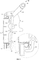
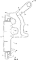
- FIGS. 1-8 illustrate examples of the vent door system according to various embodiments of the present invention.
- the system generally labeled 10, is integrated with an aircraft door 8 in this example.
- the aircraft door 8 has a vent opening 9 (shown in FIG. 6 ), around which a vent door frame 12 is disposed.
- the vent door frame 12 is attached to the aircraft door 8.
- the system also includes a vent door 14, which has an open position and a closed position.
- a flexible seal 13 is attached to the vent door 14. When in its closed position, a peripheral lip 15 of the vent door 14 is seated against the seal 13 and within the opening around which the vent door frame 12 is disposed.
- the vent door 14 includes a front panel 18 and a wall 20.
- the front panel 18 and the wall 20 define a cavity 22.
- the vent door 14 further includes a first generally planar member 24 and a second generally planar member 26 that are integrally formed with the front panel 18 and run along the length of the vent door 14.
- the vent door 14 further includes a first rib 27 and a second rib 28, also integrally formed with the first panel 18.
- Attached to the vent door 14 are two brackets 62 and 64. The brackets 62 and 64 are fastened to the vent door 14 by bolts.
- the vent door system 10 further includes a first cam 16 and a second cam 17. Both the first and second cams 16 and 17 are shown in FIG. 1 . In FIGS. 2 , 3 , and 7 , only the second cam 17 is shown. In FIGS. 4 , 5 , 6 , and 8 , only the first cam 16 is shown.
- the first cam 16 is attached to the vent door 14 at points 16a and 16b, while the second cam 17 is attached to the vent door 14 at points 17a & 17b.
- the vent door frame 12 also includes a hinge 19.
- the first cam 16 is attached to the hinge 19 at point 16c, which the second cam 17 is attached to the hinge 19 at point 17c.
- the first can 16 has defined thereon a groove 16d.
- the second cam 17 has defined thereon a groove 17d.
- the vent door 14 moves from its open position to its closed position and vice versa via the movement of the first and second cams 16 and 17.
- the first and second cams 16 and 17 pivot about the hinge 19, taking the attached vent door 14 with them.
- the lever 50 is an elongated member that has a first end 52, a middle portion 54 and a second end 56.
- the first end 52 has two generally planar members 52a and 52b that face one another and are generally parallel to each other. Between the two planar members 52a and 52b is a gap.
- a pin 58 connects the two planar members 52a and 52b across the gap.
- the middle portion 54 of the lever 50 is generally solid. Between the middle portion 54 and the second end 56 is a rounded portion 60.
- the second end 56 of the lever 50 is generally solid and hooks at about a 90 degree angle.
- the lever 50 is attached to the vent door 14 by a bolt 58 that extends through a sleeve 51 that passes through a hole in the rounded portion 60 of the lever 50 and is anchored by the brackets 62 and 64.
- the lever 50 pivots about the sleeve 51.
- the vent door system 10 also includes movement assembly, which imparts the force to the first and second cams 16 and 17 necessary to move the vent door 14 from its open to its closed position and vice versa.
- the movement assembly generally labelled 30, includes a rod 32 (shown in FIG. 1 ) that is rotatable around its longitudinal axis, a first arm 34 [referred to as 'an arm (34)' in the attached claims], second arm 36 [referred to as 'a further arm (36)' in the attached claims] and third arm 38 that are attached to the rod 32.
- the first arm 34 has a first end 35, which is attached to the rod 32, and a second end 37, which is hooked.
- the second arm 36 has a first end and a second end. The first end of the second arm 36 is attached to the rod 32.
- a roller 40 Disposed on the second end of the second arm is a roller 40.
- the third arm 38 has a first end and a second end. The first end of the third arm 38 is attached to the rod 32.
- a roller 42 Disposed on the second end of the third arm 38 is a roller 42.
- the roller 40 of the second arm 36 is disposed in the groove 16d of the first cam 16, and the roller 42 of the third arm 38 is disposed within the groove 17d of the second cam 17.
- the rollers 40 and 42 rotate against the profile of the respective grooves 16d and 17d of the first cam 16 and the second cam 17, and the first and second arms 36 and 38 pull the first and second cams 16 and 17 in proportion to the profile of the grooves.
- This pulling force causes the cams 16 and 17, along with the vent door 14, to pivot counterclockwise (from the perspective of FIGS. 4-6 ) about the hinge 19.
- the first arm 34 decouples from the lever 50.
- the vent door 14 will have opened about 45 degrees.
- the rod 32 rotates clockwise (from the perspective of FIGS.
- the vent door system 10 includes a second lever 70 that is attached to the aircraft door 8 by a pivot 72.
- the second lever 70 has a first section 74 and a second section 76.
- the first section 74 is disposed between the second section 76 and the door 8 and has a hole through which the pivot 72 passes.
- the second section 76 is disposed on top of the first section 74 and is between the first section 74 and the second end 56 of the lever 50.
- the first section 74 has a first portion 78 that slopes at an acute angle relative to the door 8, and a second portion 80 that curves upward to a point that is substantially vertical relative to the door 8.
- the second lever 70 is disposed within a depression 82 of the door 8, so that it sits below the lever of the vent door 14. When the vent door 14 is in the closed position, the tip of the second portion 80 is just below or touches the peripheral lip 15 of the vent door 14.
- the remaining portions of the vent door system 10 have the same structures shown in FIGS. 1-6 and previously described.
- the rod 32 rotates (counterclockwise from the perspective of FIGS. 7-8 ). This rotation causes the first arm 34, the second arm 36 and the third arm 38 to rotate at or near 5 degrees (also counterclockwise from the perspective FIGS. 7-8 ).
- the rotation of the first arm 34 pushes the lever 50 against the first portion 78 of the second section 74 of second lever 70.
- the second lever 70 rotates clockwise about the pivot 72.
- the second portion 80 of the second section 74 of the second lever 70 pushes upward against the lip 15 of the vent door 14 thereby breaking ice that may have been formed between the vent door 14 and the frame 12.
- the rollers 40 and 42 rotate against the profile of the respective grooves 16d and 17d of the first cam 16 and the second cam 17, and the first and second arms 36 and 38 pull the first and second cams 16 and 17 in proportion to the profile of the grooves.
- This pulling force causes the cams 16 and 17, along with the vent door 14, to pivot counterclockwise (from the perspective of FIGS. 7-8 ) about the hinge 19 in the same fashion as shown in the description of the previous embodiment in FIGS. 4-6 .
- the first arm 34 decouples from the lever 50.
- the vent door 14 will have opened about 45 degrees.
- the rod 32 rotates clockwise (from the perspective of FIGS. 7-8 ), thereby moving the first, second and third arms 34, 36 and 38 clockwise.
- the action of the second and third arms 36 and 38 along with the rollers 40 and 42 force the first and second cams 16 and 17 to rotate clockwise (from the perspective of FIGS. 7-8 ) about the hinge 19, which moves the vent door 14 into its closed position.
- the first arm 34 reconnects with the first lever 50.
Landscapes
- Engineering & Computer Science (AREA)
- Mechanical Engineering (AREA)
- Aviation & Aerospace Engineering (AREA)
- Specific Sealing Or Ventilating Devices For Doors And Windows (AREA)
- Air-Conditioning For Vehicles (AREA)
Claims (12)
- Système de volet d'aération comprenant :un volet d'aération (14) ;une surface au-delà du volet d'aération (14) ;une came disposée sur le volet d'aération (14), la came (16) présentant une rainure (16d) définie sur celle-ci ;un ensemble de déplacement (30) comprenant un galet (40), un premier bras (34) et un deuxième bras (36), le galet (40) étant disposé à l'intérieur de la rainure (16d), le deuxième bras (36) étant attaché au galet (40) de manière que lorsque le deuxième bras (36) pivote, le galet (40) roule le long de la rainure (16d), en sollicitant ainsi la came (16) et le volet d'aération (14) pour qu'ils pivotent à partir d'une ouverture d'aération (9) ;un levier (50) accouplé au premier bras (34), une partie du levier (50) s'étendant au-delà et à proximité du périmètre du volet d'aération (14) ;une tige (32) ayant un axe longitudinal, le premier bras (34) et le deuxième bras (36) étant reliés à la tige (32) et agencés pour pivoter autour de l'axe longitudinal, de manière que le premier bras (34) et le deuxième bras (36) se déplacent de façon correspondante ; etde manière que lorsque la tige (32) tourne sur son axe longitudinal, le deuxième bras (36) fait rouler le galet (40) le long de la rainure (16d), le premier bras (34) fait pivoter le levier (50), en sollicitant ainsi ladite partie du levier (50) qui s'étend au-delà du volet d'aération (14) contre ladite surface au-delà du volet d'aération (14), dans une direction opposée à la direction dans laquelle s'ouvre le volet d'aération (14), en forçant ainsi le volet d'aération (14) à s'ouvrir.
- Système selon la revendication 1, dans lequel la came (16) est une première came, le système comprenant en outre une seconde came (17) disposée sur le volet d'aération (14), généralement parallèle à la première came (16) et en regard de celle-ci, sur la seconde came (17) étant définie une rainure (17d), l'ensemble de déplacement (30) comprend en outre un troisième bras (38), le troisième bras comportant un galet (42) qui est disposé à l'intérieur de la rainure (17d) de la seconde came (17), le troisième bras (38) étant relié à la tige (32).
- Système selon la revendication 1, dans lequel :le volet d'aération (14) est attaché à une porte (8) d'aéronef et a au moins une position ouverte ;le levier (50) est attaché au volet d'aération de façon à pouvoir pivoter ;le levier (50) est un premier levier qui est accouplé au premier bras (34) lorsque le volet d'aération (14) est dans sa position fermée et désaccouplé du premier bras (34) lorsque le volet d'aération (14) est dans sa position ouverte, le système comprenant en outre :un second levier (70) attaché à la porte d'aéronef (8) de façon à pouvoir pivoter, dans lequel la surface au-delà du volet d'aération (14) se situe sur une première partie (78) du second levier (70) et est au contact du premier levier (50) et une seconde partie (80) du second levier (70) est au contact du volet d'aération (14).
- Système selon la revendication 3, dans lequel la première partie (78) et la seconde partie (80) du second levier (70) se trouvent sur des côtés opposés du pivot du second levier (70).
- Système selon la revendication 3, dans lequel le premier bras (34) présente une extrémité en crochet (37), et le premier levier (50) présente une première extrémité (52) qui procure ladite partie s'étendant au-delà de la périphérie du volet d'aération (14) et une seconde extrémité (56), l'extrémité en crochet (37) du premier bras (34) étant accouplée à la seconde extrémité (56) du premier levier (50), lorsque le volet d'aération (14) est dans sa position fermée.
- Système selon la revendication 5, dans lequel lorsque l'ensemble de déplacement (30) tire le volet d'aération (14) vers sa position ouverte, l'extrémité en crochet (37) du premier bras (34) tire sur la seconde extrémité (56) du premier levier (50), ce qui a pour effet de faire pivoter le premier levier (50) et de solliciter la première extrémité (52) du premier levier (50) contre la surface de la première partie (78) du second levier (70).
- Système selon la revendication 3, dans lequel la came (16) est une première came, le système comprenant en outre une seconde came (17) attachée au volet d'aération (14), généralement parallèle à la première came (16) et en regard de celle-ci, sur la seconde came (17) étant définie une rainure (17d), dans lequel l'ensemble de déplacement (30) comporte un troisième bras (38) auquel est attaché un galet (42), de manière que lorsque le troisième bras (38) pivote, le galet (42) du troisième bras (38) roule le long de la rainure (17d) de la seconde came (17) et sollicite ainsi la seconde came (17) et le volet d'aération (14) à l'opposé d'une ouverture d'aération (9) de la porte d'aération (8).
- Système selon la revendication 3, dans lequel le premier levier (50) est attaché au volet d'aération (14) de façon à pouvoir pivoter, et au cours de l'ouverture du volet d'aération (14), le premier bras (34) sollicite la partie du premier levier (50) qui s'étend au-delà du volet d'aération (14) contre le second levier (70) qui à son tour, pivote et applique une pression sur une lèvre périphérique (15) du volet d'aération (14), en sollicitant ainsi le volet d'aération (14) pour l'ouvrir.
- Système selon la revendication 1, dans lequel le volet d'aération (14) comprend un panneau généralement plan (18), une paroi (20) qui entoure le panneau (18) et lui est généralement perpendiculaire, le panneau et la paroi définissant une cavité (22), et un élément généralement plan (24) disposé à l'intérieur de la cavité (22) et attaché au panneau (18), et dans lequel la came (16) est attachée à l'élément (24).
- Système selon la revendication 1, comprenant en outre une porte d'aéronef (8) présentant une ouverture d'aération (9) définie dans celle-ci, dans lequel, lorsque le volet d'aération (14) est dans une position fermée, le volet d'aération (14) est installé à l'intérieur de l'ouverture d'aération (9).
- Système selon la revendication 1, comprenant en outre :une porte d'aéronef (8) présentant une ouverture d'aération (9),le volet d'aération (14) ayant une position ouverte et une position fermée, le volet d'aération (14) étant installé à l'intérieur de l'ouverture d'aération (9) lorsque le volet d'aération (14) est dans la position fermée ;la tige (32) étant disposée à proximité du volet d'aération (14) ;le premier bras (34) et le deuxième bras (36) étant généralement perpendiculaires à la tige (32) ;le bras (34) ayant une extrémité en crochet (37) ;la came (16) comportant une première partie qui est attachée au volet d'aération (14) et une seconde partie qui est attachée à une surface de la porte d'aéronef (8) de façon à pouvoir pivoter, dans lequel le levier (50) est un premier levier, une première extrémité (52) du premier levier (50) étant accouplée à l'extrémité en crochet (37) du premier bras (34) lorsque le volet d'aération (14) est dans la position fermée et une seconde extrémité (56) du premier levier (50) procurant ladite partie s'étendant au-delà de la périphérie du volet d'aération (14) ; etun second levier (70) sur lequel se situe la surface au-delà du volet d'aération (14), dans lequel le second levier (70) est attaché à la porte d'aéronef (8) de façon à pouvoir pivoter, la seconde extrémité du premier levier (50) sollicitant le second levier (70) pour qu'il pivote en réponse au déplacement du premier bras (34), le second levier (70) sollicitant le volet d'aération (14) vers la position ouverte, en réponse à la sollicitation de la seconde extrémité du premier levier (50).
- Système selon la revendication 1, dans lequel le volet d'aération (14) comprend un panneau généralement plan (18), une paroi (20) qui entoure le panneau (18) et lui est généralement perpendiculaire, le panneau et la paroi définissant une cavité (22), et un élément généralement plan (24) disposé à l'intérieur de la cavité (22) et attaché au panneau (18), et dans lequel l'ensemble de déplacement (30) est attaché à l'élément généralement plan (24).
Applications Claiming Priority (2)
| Application Number | Priority Date | Filing Date | Title |
|---|---|---|---|
| US92843507P | 2007-05-09 | 2007-05-09 | |
| PCT/US2008/063199 WO2008141146A1 (fr) | 2007-05-09 | 2008-05-09 | Système de volet d'air avec mécanisme de levier |
Publications (3)
| Publication Number | Publication Date |
|---|---|
| EP2144809A1 EP2144809A1 (fr) | 2010-01-20 |
| EP2144809A4 EP2144809A4 (fr) | 2015-10-14 |
| EP2144809B1 true EP2144809B1 (fr) | 2018-07-11 |
Family
ID=39968655
Family Applications (1)
| Application Number | Title | Priority Date | Filing Date |
|---|---|---|---|
| EP08769382.6A Active EP2144809B1 (fr) | 2007-05-09 | 2008-05-09 | Système de volet d'air avec mécanisme de levier |
Country Status (4)
| Country | Link |
|---|---|
| US (1) | US7900870B2 (fr) |
| EP (1) | EP2144809B1 (fr) |
| RU (1) | RU2476349C2 (fr) |
| WO (1) | WO2008141146A1 (fr) |
Families Citing this family (10)
| Publication number | Priority date | Publication date | Assignee | Title |
|---|---|---|---|---|
| US20120267475A1 (en) * | 2011-04-20 | 2012-10-25 | Fernando Campos | Acoustic seal for aircraft |
| DE102011114643B4 (de) * | 2011-09-30 | 2016-03-24 | Airbus Operations Gmbh | Betätigungsvorrichtung zum Öffnen einer Notausgangsklappe einer Cockpittür |
| FR3006993B1 (fr) | 2013-06-14 | 2018-01-05 | Latecoere | Procede et systeme d'antigivrage / degivrage de porte d'aeronef et porte d'aeronef equipee d'un tel systeme |
| US9517830B2 (en) * | 2014-03-18 | 2016-12-13 | The Boeing Company | Seal design for vehicle and structure application |
| US10240389B2 (en) * | 2015-09-30 | 2019-03-26 | Arconic Inc. | Pressure relief door |
| RU2685634C1 (ru) * | 2018-04-03 | 2019-04-22 | Публичное акционерное общество "Научно-производственная корпорация "Иркут" | Устройство управления дверью самолёта |
| BR102021018231A2 (pt) * | 2020-11-05 | 2022-05-17 | The Boeing Company | Conjunto de travamento de pressão coaxial |
| CN112591071B (zh) * | 2020-12-17 | 2022-03-15 | 中航沈飞民用飞机有限责任公司 | 一种舱门提升开启破冰机构 |
| CN112550665B (zh) * | 2021-02-24 | 2021-04-30 | 中国空气动力研究与发展中心低速空气动力研究所 | 一种基于弹性蒙皮的飞机除冰装置 |
| EP4098555B1 (fr) * | 2021-06-01 | 2023-08-02 | Airbus Operations GmbH | Unité de porte pour un véhicule |
Family Cites Families (14)
| Publication number | Priority date | Publication date | Assignee | Title |
|---|---|---|---|---|
| GB1291854A (en) * | 1969-02-07 | 1972-10-04 | British Aircraft Corp Ltd | Aircraft doors |
| US4125235A (en) * | 1977-04-04 | 1978-11-14 | The Boeing Company | Apparatus for opening an aircraft door and for arming and disarming an escape slide deploying mechanism |
| US4473201A (en) * | 1982-10-29 | 1984-09-25 | The Boeing Company | Canopy-type aircraft cargo door and actuating mechanisms |
| US4497462A (en) * | 1983-03-28 | 1985-02-05 | The Boeing Company | Outward opening electrically powered plug-type cargo door |
| SU1736844A1 (ru) * | 1989-06-19 | 1992-05-30 | Саратовский Авиационный Институт | Устройство навески и креплени двери летательного аппарата |
| US5031863A (en) | 1989-12-21 | 1991-07-16 | The Boeing Company | Upward/outward opening, plug-type overwing emergency exit hatch |
| US5305969A (en) * | 1991-07-16 | 1994-04-26 | The Boeing Company | Aircraft door latch lock mechanism |
| US5337977A (en) * | 1993-01-29 | 1994-08-16 | The Boeing Company | Vent-latch interlock assembly for an aircraft door |
| US5931415A (en) * | 1997-05-09 | 1999-08-03 | The Boeing Company | Plug-type overwing emergency exit door assembly |
| US5846127A (en) * | 1997-12-04 | 1998-12-08 | Kile; Walter F. | Apparatus for venting |
| FR2794717B1 (fr) * | 1999-06-10 | 2001-09-28 | D Aviat Latecoere Soc Ind | Perfectionnements aux portes de soutes pour aeronefs |
| DE10020825B4 (de) * | 2000-04-28 | 2006-08-24 | Eurocopter Deutschland Gmbh | Verfahren und Vorrichtung zum Schliessen einer Tür eines Flugzeuges |
| US6454210B1 (en) * | 2000-07-13 | 2002-09-24 | Wesley M. Plattner | Aircraft vent and cargo door locking mechanism |
| FR2864021B1 (fr) * | 2003-12-19 | 2006-05-26 | Lacroix Soc E | Dispositif de commande a deplacement d'un element de fermeture pour vehicule |
-
2008
- 2008-05-09 WO PCT/US2008/063199 patent/WO2008141146A1/fr not_active Ceased
- 2008-05-09 US US12/118,080 patent/US7900870B2/en active Active
- 2008-05-09 RU RU2009145523/11A patent/RU2476349C2/ru active
- 2008-05-09 EP EP08769382.6A patent/EP2144809B1/fr active Active
Non-Patent Citations (1)
| Title |
|---|
| None * |
Also Published As
| Publication number | Publication date |
|---|---|
| RU2009145523A (ru) | 2011-06-20 |
| EP2144809A1 (fr) | 2010-01-20 |
| RU2476349C2 (ru) | 2013-02-27 |
| EP2144809A4 (fr) | 2015-10-14 |
| WO2008141146A1 (fr) | 2008-11-20 |
| US20080277530A1 (en) | 2008-11-13 |
| US7900870B2 (en) | 2011-03-08 |
Similar Documents
| Publication | Publication Date | Title |
|---|---|---|
| US7900870B2 (en) | Vent door system with lever mechanism | |
| US8342920B2 (en) | Outflow valve having J-shaped bellmouth and cabin pressure control system employing the same | |
| EP1438473B1 (fr) | Pene dormant sensible a la pression | |
| EP3774526B1 (fr) | Ensemble de porte comportant une charnière à deux goupilles | |
| EP3792174B1 (fr) | Mécanisme de porte | |
| US5305969A (en) | Aircraft door latch lock mechanism | |
| JP2011509868A (ja) | 通気フラップを備えた加圧航空機ドア設備 | |
| EP2885205B1 (fr) | Ensemble porte pour l'intérieur d'un avion | |
| US9707831B2 (en) | Active glass retention system | |
| EP3219526B1 (fr) | Appareil pour une fenêtre | |
| EP3336291B1 (fr) | Ensemble à double verrouillage pour structures ouvrables | |
| EP3170750B1 (fr) | Soupape d'évacuation à récupération de poussée à 2 volets repliables avec un volet à air dynamique | |
| US9630700B2 (en) | Device for opening an aircraft door | |
| JP2005104428A (ja) | 航空機の操縦室ドア | |
| EP2567895B1 (fr) | Soupape d'évacuation à récupération de poussée avec porte simple unique pliable et procédé de commande de pression de cabine d'aéronef | |
| US11820484B2 (en) | Aircraft door having a mechanism for conditional opening along two trajectories | |
| US7887106B2 (en) | Floor lock | |
| CN115432167A (zh) | 用于交通工具的门单元 | |
| EP1370435B1 (fr) | Agencement dans une structure de panneau d'ouverture | |
| US10472041B2 (en) | System and method for flag door operation | |
| KR101536893B1 (ko) | 문 닫힘 제어 기능을 갖는 경첩 | |
| US7331547B2 (en) | Device for facilitating the lowering of a landing gear by gravity | |
| CN209365859U (zh) | 一种自动伸缩侧门系统 | |
| US20100019184A1 (en) | Valve seal with integral flexure joints | |
| US20200190875A1 (en) | Locking element stable under panel distortion |
Legal Events
| Date | Code | Title | Description |
|---|---|---|---|
| PUAI | Public reference made under article 153(3) epc to a published international application that has entered the european phase |
Free format text: ORIGINAL CODE: 0009012 |
|
| 17P | Request for examination filed |
Effective date: 20091106 |
|
| AK | Designated contracting states |
Kind code of ref document: A1 Designated state(s): AT BE BG CH CY CZ DE DK EE ES FI FR GB GR HR HU IE IS IT LI LT LU LV MC MT NL NO PL PT RO SE SI SK TR |
|
| AX | Request for extension of the european patent |
Extension state: AL BA MK RS |
|
| DAX | Request for extension of the european patent (deleted) | ||
| REG | Reference to a national code |
Ref country code: HK Ref legal event code: DE Ref document number: 1139630 Country of ref document: HK |
|
| RA4 | Supplementary search report drawn up and despatched (corrected) |
Effective date: 20150910 |
|
| RIC1 | Information provided on ipc code assigned before grant |
Ipc: B64C 1/14 20060101AFI20150904BHEP Ipc: E05B 17/00 20060101ALI20150904BHEP |
|
| STAA | Information on the status of an ep patent application or granted ep patent |
Free format text: STATUS: EXAMINATION IS IN PROGRESS |
|
| 17Q | First examination report despatched |
Effective date: 20161212 |
|
| GRAP | Despatch of communication of intention to grant a patent |
Free format text: ORIGINAL CODE: EPIDOSNIGR1 |
|
| STAA | Information on the status of an ep patent application or granted ep patent |
Free format text: STATUS: GRANT OF PATENT IS INTENDED |
|
| INTG | Intention to grant announced |
Effective date: 20180322 |
|
| GRAS | Grant fee paid |
Free format text: ORIGINAL CODE: EPIDOSNIGR3 |
|
| GRAA | (expected) grant |
Free format text: ORIGINAL CODE: 0009210 |
|
| STAA | Information on the status of an ep patent application or granted ep patent |
Free format text: STATUS: THE PATENT HAS BEEN GRANTED |
|
| AK | Designated contracting states |
Kind code of ref document: B1 Designated state(s): AT BE BG CH CY CZ DE DK EE ES FI FR GB GR HR HU IE IS IT LI LT LU LV MC MT NL NO PL PT RO SE SI SK TR |
|
| REG | Reference to a national code |
Ref country code: GB Ref legal event code: FG4D |
|
| REG | Reference to a national code |
Ref country code: CH Ref legal event code: EP |
|
| REG | Reference to a national code |
Ref country code: AT Ref legal event code: REF Ref document number: 1016610 Country of ref document: AT Kind code of ref document: T Effective date: 20180715 |
|
| REG | Reference to a national code |
Ref country code: IE Ref legal event code: FG4D |
|
| REG | Reference to a national code |
Ref country code: DE Ref legal event code: R096 Ref document number: 602008055968 Country of ref document: DE |
|
| REG | Reference to a national code |
Ref country code: NL Ref legal event code: FP |
|
| REG | Reference to a national code |
Ref country code: LT Ref legal event code: MG4D |
|
| REG | Reference to a national code |
Ref country code: HK Ref legal event code: WD Ref document number: 1139630 Country of ref document: HK |
|
| REG | Reference to a national code |
Ref country code: AT Ref legal event code: MK05 Ref document number: 1016610 Country of ref document: AT Kind code of ref document: T Effective date: 20180711 |
|
| PG25 | Lapsed in a contracting state [announced via postgrant information from national office to epo] |
Ref country code: GR Free format text: LAPSE BECAUSE OF FAILURE TO SUBMIT A TRANSLATION OF THE DESCRIPTION OR TO PAY THE FEE WITHIN THE PRESCRIBED TIME-LIMIT Effective date: 20181012 Ref country code: NO Free format text: LAPSE BECAUSE OF FAILURE TO SUBMIT A TRANSLATION OF THE DESCRIPTION OR TO PAY THE FEE WITHIN THE PRESCRIBED TIME-LIMIT Effective date: 20181011 Ref country code: AT Free format text: LAPSE BECAUSE OF FAILURE TO SUBMIT A TRANSLATION OF THE DESCRIPTION OR TO PAY THE FEE WITHIN THE PRESCRIBED TIME-LIMIT Effective date: 20180711 Ref country code: BG Free format text: LAPSE BECAUSE OF FAILURE TO SUBMIT A TRANSLATION OF THE DESCRIPTION OR TO PAY THE FEE WITHIN THE PRESCRIBED TIME-LIMIT Effective date: 20181011 Ref country code: LT Free format text: LAPSE BECAUSE OF FAILURE TO SUBMIT A TRANSLATION OF THE DESCRIPTION OR TO PAY THE FEE WITHIN THE PRESCRIBED TIME-LIMIT Effective date: 20180711 Ref country code: IS Free format text: LAPSE BECAUSE OF FAILURE TO SUBMIT A TRANSLATION OF THE DESCRIPTION OR TO PAY THE FEE WITHIN THE PRESCRIBED TIME-LIMIT Effective date: 20181111 Ref country code: PL Free format text: LAPSE BECAUSE OF FAILURE TO SUBMIT A TRANSLATION OF THE DESCRIPTION OR TO PAY THE FEE WITHIN THE PRESCRIBED TIME-LIMIT Effective date: 20180711 Ref country code: FI Free format text: LAPSE BECAUSE OF FAILURE TO SUBMIT A TRANSLATION OF THE DESCRIPTION OR TO PAY THE FEE WITHIN THE PRESCRIBED TIME-LIMIT Effective date: 20180711 Ref country code: SE Free format text: LAPSE BECAUSE OF FAILURE TO SUBMIT A TRANSLATION OF THE DESCRIPTION OR TO PAY THE FEE WITHIN THE PRESCRIBED TIME-LIMIT Effective date: 20180711 |
|
| PG25 | Lapsed in a contracting state [announced via postgrant information from national office to epo] |
Ref country code: HR Free format text: LAPSE BECAUSE OF FAILURE TO SUBMIT A TRANSLATION OF THE DESCRIPTION OR TO PAY THE FEE WITHIN THE PRESCRIBED TIME-LIMIT Effective date: 20180711 Ref country code: LV Free format text: LAPSE BECAUSE OF FAILURE TO SUBMIT A TRANSLATION OF THE DESCRIPTION OR TO PAY THE FEE WITHIN THE PRESCRIBED TIME-LIMIT Effective date: 20180711 Ref country code: ES Free format text: LAPSE BECAUSE OF FAILURE TO SUBMIT A TRANSLATION OF THE DESCRIPTION OR TO PAY THE FEE WITHIN THE PRESCRIBED TIME-LIMIT Effective date: 20180711 |
|
| REG | Reference to a national code |
Ref country code: DE Ref legal event code: R097 Ref document number: 602008055968 Country of ref document: DE |
|
| PG25 | Lapsed in a contracting state [announced via postgrant information from national office to epo] |
Ref country code: EE Free format text: LAPSE BECAUSE OF FAILURE TO SUBMIT A TRANSLATION OF THE DESCRIPTION OR TO PAY THE FEE WITHIN THE PRESCRIBED TIME-LIMIT Effective date: 20180711 Ref country code: CZ Free format text: LAPSE BECAUSE OF FAILURE TO SUBMIT A TRANSLATION OF THE DESCRIPTION OR TO PAY THE FEE WITHIN THE PRESCRIBED TIME-LIMIT Effective date: 20180711 Ref country code: IT Free format text: LAPSE BECAUSE OF FAILURE TO SUBMIT A TRANSLATION OF THE DESCRIPTION OR TO PAY THE FEE WITHIN THE PRESCRIBED TIME-LIMIT Effective date: 20180711 Ref country code: RO Free format text: LAPSE BECAUSE OF FAILURE TO SUBMIT A TRANSLATION OF THE DESCRIPTION OR TO PAY THE FEE WITHIN THE PRESCRIBED TIME-LIMIT Effective date: 20180711 |
|
| PLBE | No opposition filed within time limit |
Free format text: ORIGINAL CODE: 0009261 |
|
| STAA | Information on the status of an ep patent application or granted ep patent |
Free format text: STATUS: NO OPPOSITION FILED WITHIN TIME LIMIT |
|
| PG25 | Lapsed in a contracting state [announced via postgrant information from national office to epo] |
Ref country code: DK Free format text: LAPSE BECAUSE OF FAILURE TO SUBMIT A TRANSLATION OF THE DESCRIPTION OR TO PAY THE FEE WITHIN THE PRESCRIBED TIME-LIMIT Effective date: 20180711 Ref country code: SK Free format text: LAPSE BECAUSE OF FAILURE TO SUBMIT A TRANSLATION OF THE DESCRIPTION OR TO PAY THE FEE WITHIN THE PRESCRIBED TIME-LIMIT Effective date: 20180711 |
|
| 26N | No opposition filed |
Effective date: 20190412 |
|
| PG25 | Lapsed in a contracting state [announced via postgrant information from national office to epo] |
Ref country code: SI Free format text: LAPSE BECAUSE OF FAILURE TO SUBMIT A TRANSLATION OF THE DESCRIPTION OR TO PAY THE FEE WITHIN THE PRESCRIBED TIME-LIMIT Effective date: 20180711 |
|
| REG | Reference to a national code |
Ref country code: CH Ref legal event code: PL |
|
| PG25 | Lapsed in a contracting state [announced via postgrant information from national office to epo] |
Ref country code: MC Free format text: LAPSE BECAUSE OF FAILURE TO SUBMIT A TRANSLATION OF THE DESCRIPTION OR TO PAY THE FEE WITHIN THE PRESCRIBED TIME-LIMIT Effective date: 20180711 Ref country code: CH Free format text: LAPSE BECAUSE OF NON-PAYMENT OF DUE FEES Effective date: 20190531 Ref country code: LI Free format text: LAPSE BECAUSE OF NON-PAYMENT OF DUE FEES Effective date: 20190531 |
|
| REG | Reference to a national code |
Ref country code: BE Ref legal event code: MM Effective date: 20190531 |
|
| PG25 | Lapsed in a contracting state [announced via postgrant information from national office to epo] |
Ref country code: LU Free format text: LAPSE BECAUSE OF NON-PAYMENT OF DUE FEES Effective date: 20190509 |
|
| PG25 | Lapsed in a contracting state [announced via postgrant information from national office to epo] |
Ref country code: TR Free format text: LAPSE BECAUSE OF FAILURE TO SUBMIT A TRANSLATION OF THE DESCRIPTION OR TO PAY THE FEE WITHIN THE PRESCRIBED TIME-LIMIT Effective date: 20180711 |
|
| PG25 | Lapsed in a contracting state [announced via postgrant information from national office to epo] |
Ref country code: IE Free format text: LAPSE BECAUSE OF NON-PAYMENT OF DUE FEES Effective date: 20190509 |
|
| PG25 | Lapsed in a contracting state [announced via postgrant information from national office to epo] |
Ref country code: BE Free format text: LAPSE BECAUSE OF NON-PAYMENT OF DUE FEES Effective date: 20190531 |
|
| PG25 | Lapsed in a contracting state [announced via postgrant information from national office to epo] |
Ref country code: PT Free format text: LAPSE BECAUSE OF FAILURE TO SUBMIT A TRANSLATION OF THE DESCRIPTION OR TO PAY THE FEE WITHIN THE PRESCRIBED TIME-LIMIT Effective date: 20181111 |
|
| PG25 | Lapsed in a contracting state [announced via postgrant information from national office to epo] |
Ref country code: CY Free format text: LAPSE BECAUSE OF FAILURE TO SUBMIT A TRANSLATION OF THE DESCRIPTION OR TO PAY THE FEE WITHIN THE PRESCRIBED TIME-LIMIT Effective date: 20180711 |
|
| PG25 | Lapsed in a contracting state [announced via postgrant information from national office to epo] |
Ref country code: HU Free format text: LAPSE BECAUSE OF FAILURE TO SUBMIT A TRANSLATION OF THE DESCRIPTION OR TO PAY THE FEE WITHIN THE PRESCRIBED TIME-LIMIT; INVALID AB INITIO Effective date: 20080509 Ref country code: MT Free format text: LAPSE BECAUSE OF FAILURE TO SUBMIT A TRANSLATION OF THE DESCRIPTION OR TO PAY THE FEE WITHIN THE PRESCRIBED TIME-LIMIT Effective date: 20180711 |
|
| REG | Reference to a national code |
Ref country code: DE Ref legal event code: R082 Ref document number: 602008055968 Country of ref document: DE Representative=s name: KRAUS & LEDERER PARTGMBB, DE |
|
| PGFP | Annual fee paid to national office [announced via postgrant information from national office to epo] |
Ref country code: NL Payment date: 20250423 Year of fee payment: 18 |
|
| PGFP | Annual fee paid to national office [announced via postgrant information from national office to epo] |
Ref country code: DE Payment date: 20250423 Year of fee payment: 18 |
|
| PGFP | Annual fee paid to national office [announced via postgrant information from national office to epo] |
Ref country code: GB Payment date: 20250423 Year of fee payment: 18 |
|
| PGFP | Annual fee paid to national office [announced via postgrant information from national office to epo] |
Ref country code: FR Payment date: 20250424 Year of fee payment: 18 |