EP2145100B1 - Soupape électromagnétique - Google Patents
Soupape électromagnétique Download PDFInfo
- Publication number
- EP2145100B1 EP2145100B1 EP08708642A EP08708642A EP2145100B1 EP 2145100 B1 EP2145100 B1 EP 2145100B1 EP 08708642 A EP08708642 A EP 08708642A EP 08708642 A EP08708642 A EP 08708642A EP 2145100 B1 EP2145100 B1 EP 2145100B1
- Authority
- EP
- European Patent Office
- Prior art keywords
- armature
- wings
- injection valve
- valve
- anchor
- Prior art date
- Legal status (The legal status is an assumption and is not a legal conclusion. Google has not performed a legal analysis and makes no representation as to the accuracy of the status listed.)
- Not-in-force
Links
Images


Classifications
-
- F—MECHANICAL ENGINEERING; LIGHTING; HEATING; WEAPONS; BLASTING
- F02—COMBUSTION ENGINES; HOT-GAS OR COMBUSTION-PRODUCT ENGINE PLANTS
- F02M—SUPPLYING COMBUSTION ENGINES IN GENERAL WITH COMBUSTIBLE MIXTURES OR CONSTITUENTS THEREOF
- F02M51/00—Fuel-injection apparatus characterised by being operated electrically
- F02M51/06—Injectors peculiar thereto with means directly operating the valve needle
- F02M51/061—Injectors peculiar thereto with means directly operating the valve needle using electromagnetic operating means
- F02M51/0625—Injectors peculiar thereto with means directly operating the valve needle using electromagnetic operating means characterised by arrangement of mobile armatures
- F02M51/0635—Injectors peculiar thereto with means directly operating the valve needle using electromagnetic operating means characterised by arrangement of mobile armatures having a plate-shaped or undulated armature not entering the winding
-
- F—MECHANICAL ENGINEERING; LIGHTING; HEATING; WEAPONS; BLASTING
- F02—COMBUSTION ENGINES; HOT-GAS OR COMBUSTION-PRODUCT ENGINE PLANTS
- F02M—SUPPLYING COMBUSTION ENGINES IN GENERAL WITH COMBUSTIBLE MIXTURES OR CONSTITUENTS THEREOF
- F02M61/00—Fuel-injectors not provided for in groups F02M39/00 - F02M57/00 or F02M67/00
- F02M61/16—Details not provided for in, or of interest apart from, the apparatus of groups F02M61/02 - F02M61/14
- F02M61/20—Closing valves mechanically, e.g. arrangements of springs or weights or permanent magnets; Damping of valve lift
-
- F—MECHANICAL ENGINEERING; LIGHTING; HEATING; WEAPONS; BLASTING
- F02—COMBUSTION ENGINES; HOT-GAS OR COMBUSTION-PRODUCT ENGINE PLANTS
- F02M—SUPPLYING COMBUSTION ENGINES IN GENERAL WITH COMBUSTIBLE MIXTURES OR CONSTITUENTS THEREOF
- F02M2200/00—Details of fuel-injection apparatus, not otherwise provided for
- F02M2200/30—Fuel-injection apparatus having mechanical parts, the movement of which is damped
-
- F—MECHANICAL ENGINEERING; LIGHTING; HEATING; WEAPONS; BLASTING
- F02—COMBUSTION ENGINES; HOT-GAS OR COMBUSTION-PRODUCT ENGINE PLANTS
- F02M—SUPPLYING COMBUSTION ENGINES IN GENERAL WITH COMBUSTIBLE MIXTURES OR CONSTITUENTS THEREOF
- F02M2200/00—Details of fuel-injection apparatus, not otherwise provided for
- F02M2200/30—Fuel-injection apparatus having mechanical parts, the movement of which is damped
- F02M2200/306—Fuel-injection apparatus having mechanical parts, the movement of which is damped using mechanical means
Definitions
- DE 100 08 554 A1 refers to a fuel injection valve for internal combustion engines. It is disclosed a fuel injection valve having at least two valve body parts, which rest against each other on a contact surface and are clamped by a clamping device against each other perpendicular to the contact surface. In both valve body parts an inlet channel for fuel is formed, which passes through the contact surfaces and there is a high fuel pressure. In the inlet channel, there is at least one radial extension near the contact surface of the relevant valve body part, so that this radial expansion experiences an expansion in the axial direction of the inlet channel due to the fuel pressure in the inlet channel.
- the area of the contact surface surrounding the passage of the inlet channel is pressed against the contact surface of the adjoining valve body part, so that the contact pressure of the contact surfaces increases.
- the passage of the inlet channel is thus better sealed and it can be correspondingly reduced the force of the clamping device.
- the pressurized medium in the closed state is usually enclosed in an annular pressure chamber.
- This chamber is bounded on one side by a guide and on the other side by a sealing seat, wherein guide and sealing seat have exactly the same diameter d.
- Valves are known from the prior art, which are also used in injection valves for internal combustion engines. Especially with injectors that are used in the automotive sector, fast-switching valves are required, which means that the Ventilhubweg must be traversed very quickly. Thus, such valves close at speeds of 0.5 to 1 m / s. If a valve member hits on the valve seat or a stroke stop in such a valve, mechanical vibrations in the valve are excited and the valve can bounce, which means that the valve is initially closed, but reopens after contact of the valve seat with the valve member and, for example, go through a ballistic phase of operation. Since the injection valve is not closed immediately, this can cause inaccuracies in the injection process. Likewise, in the subsequent control of the injection valve - for example in the case of a pre-injection and a main injection - The movement are disturbed such that this can be seen in a quantity deviation of the injection quantity.
- an injection valve in which the reproducible injection quantity accuracies from pilot injection phase to main injection phase to subsequent pilot injection phase are considerably increased compared with the fuel injectors known from the prior art.
- the closing speed is considerably increased, as a result of which the achievable injection quality is considerably improved.
- a favorable ratio of the natural frequencies to one another is the factor 2. This means that one of the armatures should be four times as heavy as another or the coupling of this armature wing should be four times as soft Depending on whether the realization of the mass or the rigidity takes place. Of course, combinations of stiffness and mass differences can be realized.
- FIG. 1 The representation according to FIG. 1 can be removed that an injection valve 10 has a substantially arranged in the valve body valve guide 12.
- the valve guide 12 is fixed on a plan side 32 by a valve clamping nut 24, which is only indicated here, and received stationary in the valve body of the injection valve 10.
- the injection valve 10 comprises the valve guide 12, whose lateral surface is identified by reference numeral 14. At this a sleeve-shaped here valve member 16 is guided movably in the vertical direction.
- the valve member 16 comprises an anchor bolt and an anchor plate 20, which in turn has individual armature wings 22.
- the closing direction, in which the sleeve-shaped Venfilglied 16 is moved to close a seat 30 is indicated by reference numeral 26.
- the seat 30 is formed at the transition from the plan side 32 of the valve guide 12 in the guide portion for vertical guidance of the anchor bolt 18.
- a seat is closed by the sleeve-shaped in the closing direction 26 formed valve member 16, indicated by reference numeral 34th
- Figure 1.2 shows the movement of the armature assembly after impact of the anchor bolt 18 in the seat 30 and its closing.
- the lower end face of the anchor bolt 18 does not move further, since this rests against the seat surface of the seat 30.
- the at least one formed at the opposite end of the anchor bolt 18 leads Valve blade 22 from a downward movement, from which a deflection 36 down the at least one armature blade 22 results on the anchor bolt 18.
- Figure 1.3 shows that the in Figure 1.2 indicated deflection 36 down the at least one anchor blade 22 on the anchor bolt 18 in a bend 38 goes up, which causes a Aufziehkraft 40, ie, an acting in the axial direction of the sleeve-shaped valve member 16 opening force.
- a Aufziehkraft 40 ie
- an opening force acts on the sleeve-shaped valve member, which pulls it out of the closed seat 34.
- This process of swinging back of the at least one anchor blade 22 formed on the anchor bolt 18 of the anchor assembly is referred to as "bouncing".
- the representation according to FIG. 2 the movements of the at least one anchor wing and the anchor bolt are removable.
- the at least one anchor bolt 22 and the anchor bolt 18 of the armature assembly of the injection valve 10 move synchronously in the direction of the seat 30 FIG. 2 It can be seen that a movement sequence 50 of the at least one anchor blade 22 and a movement sequence 60 of the anchor bolt 18 run synchronously.
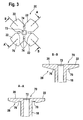
- FIG. 3 it can be seen, are formed on the anchor plate 20 there, which has a central bore 72 and whose plan side is indicated by reference numeral 70, four symmetrically extending armature vanes 22.
- the armature vanes 22 are separated from each other by slits 74.
- Two mutually opposite armature wings 22 form an armature wing pair, wherein one of the pairs of armature wings has a rigid coupling 76 to the anchor bolt 18 and the remaining further armature wing pair of the armature wing 22 has a flexible coupling 78 to the anchor bolt 18.
- section BB shows that the attached to the anchor bolt 18 of the armature assembly, opposing armature blades 22 are connected by a rigid coupling 76 with the anchor bolt 18, which results from the accumulation of material at the transition from the lateral surface 18 of the anchor bolt to the armature blades 22 ,
- FIG. 4 shows an anchor plate 20, which represents a base group 80, from which according to the invention proposed anchor assemblies comprising the anchor plate 20 and the anchor bolt 18 can be designed.
- the plan side 70 of the anchor plate 20 is divided by a slot 74 in four vanes 22.
- the armature wings 22, which are separated from each other by a slot 74, are in pairs opposite each other.
- the coupling points of the armature wing 22 to the anchor bolt 18 in the central bore 72 are all designed as rigid couplings.
- FIG. 5 shows that in this embodiment, two opposing armature vanes 22 are coupled via the rigid coupling 76 to the anchor bolt 18, while this 90 ° rotated armature vanes 22 are respectively coupled by a first slot 84 and a second slot 86 to the anchor bolt 18 ,
- flexible couplings 78 of the two mentioned armature vanes 22 with respect to the anchor bolt 18 are realized on the plan side 70 thereof in the region of the two armature vanes 22.
- Reference numeral 82 denotes a rotation axis with respect to the bend of the armature blade 22.
- FIG. 6 shows a further embodiment of flexurally soft and rigid coupling of armature wings of an anchor plate to the anchor bolt of an armature assembly.
- the plan side 70 of the armature plate 20 is also divided into four armature vanes 22 which are each oriented at right angles to each other with respect to the central bore 72.
- Two opposing armature wings 22 each form an armature wing pair.
- two opposing armature blades 22 via the rigid coupling 76 with the anchor bolt which extends in the plane parallel to the central bore 72 coupled, while the two of these armature wings 22 offset by 90 ° the armature blade 22 via the flexurally soft coupling 78 with the perpendicular to the plane according to FIG. 6 extending anchor bolt 18 are coupled.
- FIG. 7 is a further embodiment of an anchor plate of an armature assembly refer to different natural frequencies are realized.
- the plan side 70 of the armature plate 22 is divided into a number of armature blades 22, in the present example four armature blades 22.
- two opposing armature vanes are coupled via a first pair of slots 88 and a second pair of slots 90 to the core region of the planar side 70 of the armature plate 20.
- the first pair of slots 88 and the second pair of slots 90 represents a targeted weakening of the coupling of the two opposing armature wings 22.
- the two offset by 90 ° to each other arranged armature vanes 22 are coupled via the rigid coupling 76 with the core region of the armature plate 20.
- FIG. 8 shows a further embodiment of the design of the plan side of the anchor plate 20 of the armature assembly.
- FIG. 8 shows that the plan side 70 of the anchor plate 20 is divided over a four-slot 74 into four wings.
- a flexible coupling 78 is achieved two opposing armature blade 22 by the introduction of a first weakening hole 92 and a second weakening hole 94 in the plan side 70 of the anchor plate 20.
- the two offset by 90 ° to the armature blade 22 oriented armature wings 22 without weakening holes 92 and 94 are coupled via a rigid coupling 76 with the core region of the armature plate 20.
- FIG. 9 illustrates a variation of the embodiment according to FIG. 8 in which two armature vanes 22 of the armature plate 20 each have in the region of their coupling points to the core region of the armature plate 20 attenuation holes 96 and 98 with respect to the rotation.
- the first weakening bore 92 or the second weakening bore 94 is centered in the respective coupling point of the coupling point 78 of the armature blades 22 to the core region of the armature plate 20 is shown
- FIG. 9 In the anchor plate material introduced weakening holes 96, 98 mounted off-center. As a result, rotational degrees of freedom are excited. Due to the off-center arrangement of the weakening holes 96, 98 in the in FIG. 9 illustrated embodiment, can be rotational excite degrees of freedom, through which relatively easily different natural frequencies in the armature blades 22 can be constructed.
- the plan side 70 of the armature plate of the armature assembly is divided into an even number of armature blades 22, which can be realized in a particularly simple manufacturing technology by the slit 74, which is preferably a four-slot ,
- the plan side 70 of the anchor plate 20 with a triple slot, which is not shown in the drawing, and in this way the plan page 70 of the anchor plate 20 in 3 by 120 ° -Anordung to each other lying armature wings 22 to divide.
- an opposite movement of at least two wing wings also possible with this embodiment, without departing from the scope of the present invention.
- the mass moments of inertia j of the respective armature blades 22 are designed differently, so that different resonance frequencies of each two armature blades 22 to be realized.
Landscapes
- Engineering & Computer Science (AREA)
- Chemical & Material Sciences (AREA)
- Combustion & Propulsion (AREA)
- Mechanical Engineering (AREA)
- General Engineering & Computer Science (AREA)
- Physics & Mathematics (AREA)
- Electromagnetism (AREA)
- Fuel-Injection Apparatus (AREA)
- Valve Device For Special Equipments (AREA)
- Magnetically Actuated Valves (AREA)
Claims (10)
- Soupape d'injection (10), notamment pour l'injection de carburant dans des moteurs à combustion interne, comprenant un guidage de soupape (12) et un organe de soupape (16) et un module d'armature, qui présente un boulon d'armature (18) et une plaque d'armature (20), et le module d'armature (18, 20) libérant ou fermant un siège de soupape (30) de la soupape d'injection (10), caractérisée en ce que des ailettes d'armature (22) réalisées sur la plaque d'armature (20) présentent différentes fréquences propres.
- Soupape d'injection (10) selon la revendication 1, caractérisée en ce que les points d'accouplement des ailettes d'armature (22) à la plaque d'armature (20) sont réalisés sous forme de points d'accouplement rigides en flexion (76), sous forme de points d'accouplement déformables en flexion (78) ou sous forme de points d'accouplement déformables en flexion dans le sens de la rotation (82).
- Soupape d'injection (10) selon la revendication 1, caractérisée en ce que les ailettes d'armature (22) présentent à chaque fois des points d'accouplement rigides en flexion (76) ou des points d'accouplement déformables en flexion (78) appariés pour la plaque d'armature (20).
- Soupape d'injection (10) selon la revendication 1, caractérisée en ce que la plaque d'armature (20) forme avec le boulon d'armature (18) un module d'armature d'une seule pièce.
- Soupape d'injection (10) selon la revendication 1, caractérisée en ce que l'accouplement rigide en flexion (76) des ailettes d'armature (22) à la plaque d'armature (20) est réalisé par le biais de fentes (84, 86) orientées en sens inverse les unes des autres, par le biais d'ailettes d'armature (22) réalisées avec une largeur de matériau accrue, par le biais de paires de fentes (88, 90) ou par le biais d'alésages d'affaiblissement (92, 94) dans le matériau de la plaque d'armature (20).
- Soupape d'injection (10) selon la revendication 1, caractérisée en ce que les ailettes d'armature (22) présentent, à chaque fois, des paires d'accouplements rigides en flexion (76) ou d'accouplements déformables en flexion (78).
- Soupape d'injection (10) selon la revendication 1, caractérisée en ce que les ailettes d'armature (22) présentent à chaque fois par paires, un couple d'inertie de masse élevé J et un couple d'inertie de masse faible j, à chaque fois par rapport à l'axe de rotation de l'ailette d'armature (22) lors de la flexion.
- Soupape d'injection (10) selon la revendication 1, caractérisée en ce que les ailettes d'armature (22), vues dans la direction périphérique de la plaque d'armature (20) présentent à chaque fois des accouplements déformables en flexion (82).
- Soupape d'injection (10) selon la revendication 1, caractérisée en ce que les ailettes d'armature (22) sont formées sur la plaque d'armature (20) par une fente (74) et à chaque fois deux ailettes d'armature opposées (22) sont construites de manière symétrique.
- Soupape d'injection (10) selon l'une quelconque ou plusieurs des revendications précédentes, caractérisée en ce que lors du contact du module d'armature constitué de la plaque d'armature (20) et du boulon d'armature (18) dans le siège (30) contre un guidage de soupape (12), du fait de la fréquence propre différente des paires des ailettes d'armature (22), des forces d'attraction (40) actionnant l'organe de soupape (16) dans le sens de l'ouverture sont compensées.
Applications Claiming Priority (2)
| Application Number | Priority Date | Filing Date | Title |
|---|---|---|---|
| DE102007016252A DE102007016252A1 (de) | 2007-04-04 | 2007-04-04 | Magnetventil |
| PCT/EP2008/051338 WO2008122452A1 (fr) | 2007-04-04 | 2008-02-04 | Soupape électromagnétique |
Publications (2)
| Publication Number | Publication Date |
|---|---|
| EP2145100A1 EP2145100A1 (fr) | 2010-01-20 |
| EP2145100B1 true EP2145100B1 (fr) | 2010-11-24 |
Family
ID=39410278
Family Applications (1)
| Application Number | Title | Priority Date | Filing Date |
|---|---|---|---|
| EP08708642A Not-in-force EP2145100B1 (fr) | 2007-04-04 | 2008-02-04 | Soupape électromagnétique |
Country Status (5)
| Country | Link |
|---|---|
| EP (1) | EP2145100B1 (fr) |
| CN (1) | CN101802385B (fr) |
| AT (1) | ATE489553T1 (fr) |
| DE (2) | DE102007016252A1 (fr) |
| WO (1) | WO2008122452A1 (fr) |
Families Citing this family (3)
| Publication number | Priority date | Publication date | Assignee | Title |
|---|---|---|---|---|
| CN102758712A (zh) * | 2011-04-29 | 2012-10-31 | 北京亚新科天纬油泵油嘴股份有限公司 | 燃料喷射执行阀 |
| DE102015226499A1 (de) * | 2015-12-22 | 2017-06-22 | Robert Bosch Gmbh | Magnetventil für ein Kraftstoffeinspritzventil, Verfahren zum Betreiben des Magnetventils und Kraftstoffeinspritzventil mit einem solchen Magnetventil |
| DE102016225768A1 (de) * | 2016-12-21 | 2018-06-21 | Robert Bosch Gmbh | Kraftstoffinjektor und Verfahren zum Betreiben eines Kraftstoffinjektors |
Family Cites Families (6)
| Publication number | Priority date | Publication date | Assignee | Title |
|---|---|---|---|---|
| GB8519251D0 (en) * | 1985-07-31 | 1985-09-04 | Lucas Ind Plc | Fuel injector |
| US4978074A (en) * | 1989-06-21 | 1990-12-18 | General Motors Corporation | Solenoid actuated valve assembly |
| US5299776A (en) * | 1993-03-26 | 1994-04-05 | Siemens Automotive L.P. | Impact dampened armature and needle valve assembly |
| DE10008554A1 (de) | 2000-02-24 | 2001-08-30 | Bosch Gmbh Robert | Kraftstoffeinspritzventil für Brennkraftmaschinen |
| JP2006329029A (ja) * | 2005-05-25 | 2006-12-07 | Denso Corp | インジェクタ |
| JP2007064364A (ja) * | 2005-08-31 | 2007-03-15 | Denso Corp | 電磁弁 |
-
2007
- 2007-04-04 DE DE102007016252A patent/DE102007016252A1/de not_active Withdrawn
-
2008
- 2008-02-04 AT AT08708642T patent/ATE489553T1/de active
- 2008-02-04 CN CN2008800110127A patent/CN101802385B/zh not_active Expired - Fee Related
- 2008-02-04 DE DE502008001902T patent/DE502008001902D1/de active Active
- 2008-02-04 EP EP08708642A patent/EP2145100B1/fr not_active Not-in-force
- 2008-02-04 WO PCT/EP2008/051338 patent/WO2008122452A1/fr not_active Ceased
Also Published As
| Publication number | Publication date |
|---|---|
| DE102007016252A1 (de) | 2008-10-09 |
| WO2008122452A1 (fr) | 2008-10-16 |
| CN101802385B (zh) | 2012-04-18 |
| WO2008122452A8 (fr) | 2010-02-18 |
| ATE489553T1 (de) | 2010-12-15 |
| CN101802385A (zh) | 2010-08-11 |
| DE502008001902D1 (de) | 2011-01-05 |
| EP2145100A1 (fr) | 2010-01-20 |
Similar Documents
| Publication | Publication Date | Title |
|---|---|---|
| EP1259729B1 (fr) | Electrovanne destinee a la commande d'une soupape d'injection d'un moteur a combustion interne | |
| DE10100422A1 (de) | Magnetventil zur Steuerung eines Einspritzventils einer Brennkraftmaschine | |
| EP3478957B1 (fr) | Soupape d'injection d'un carburant gazeux | |
| EP2307776B1 (fr) | Delimitation d'entrefer d'electrovanne | |
| EP1234112A1 (fr) | Systeme d'injection de carburant pour moteurs a combustion interne | |
| EP1203151B1 (fr) | Electrovanne bietagee destinee a un injecteur d'un moteur a combustion | |
| EP1576278A1 (fr) | Soupape d'injection de carburant | |
| EP1390614A1 (fr) | Electrovanne de commande de soupape d'injection de moteur a combustion interne | |
| EP1576277A1 (fr) | Actionneur magnetique exempt d'impulsions rebondissantes pour des soupapes d'injection | |
| DE29713167U1 (de) | Elektromagnetischer Aktuator mit elastisch verformbarem Anker | |
| EP2145100A1 (fr) | Soupape électromagnétique | |
| DE10305985A1 (de) | Prellerfreier Magnetsteller für Einspritzventile | |
| EP3545185B1 (fr) | Valve de dosage de gaz | |
| DE102008040068B4 (de) | Konkave Luftspaltbegrenzung bei Magnetventil | |
| EP3346121B1 (fr) | Électrovanne pour un système d'injection de carburant et pompe haute pression à carburant | |
| DE2343285A1 (de) | Elektromagnetisch betaetigbares kraftstoffeinspritzventil fuer brennkraftmaschinen | |
| DE102019210614A1 (de) | Ventil zum Zumessen eines Fluids und Brennstoffeinspritzanlage | |
| DE10122168A1 (de) | Magnetventil zur Steuerung eines Einspritzventils einer Brennkraftmaschine | |
| DE102009046079A1 (de) | Mengensteuerventil, insbesondere zur Mengensteuerung einer Kraftstoff-Hochdruckpumpe | |
| DE102005058302A1 (de) | Verformungsoptimierte Ankerführung für Magnetventile | |
| EP2185808B1 (fr) | Soupape d'injection de carburant pour moteurs à combustion interne | |
| EP2035685A1 (fr) | Dispositif d'injection de carburant pour moteur à combustion interne | |
| DE102010040620A1 (de) | Magnetventil, insbesondere für einen Kraftstoffinjektor | |
| EP1325215A1 (fr) | Procede pour fabriquer un actionneur electromagnetique | |
| DE102018204025A1 (de) | Ventil zum Zumessen eines Fluids |
Legal Events
| Date | Code | Title | Description |
|---|---|---|---|
| PUAI | Public reference made under article 153(3) epc to a published international application that has entered the european phase |
Free format text: ORIGINAL CODE: 0009012 |
|
| 17P | Request for examination filed |
Effective date: 20091104 |
|
| AK | Designated contracting states |
Kind code of ref document: A1 Designated state(s): AT BE BG CH CY CZ DE DK EE ES FI FR GB GR HR HU IE IS IT LI LT LU LV MC MT NL NO PL PT RO SE SI SK TR |
|
| AX | Request for extension of the european patent |
Extension state: AL BA MK RS |
|
| DAX | Request for extension of the european patent (deleted) | ||
| GRAP | Despatch of communication of intention to grant a patent |
Free format text: ORIGINAL CODE: EPIDOSNIGR1 |
|
| GRAS | Grant fee paid |
Free format text: ORIGINAL CODE: EPIDOSNIGR3 |
|
| GRAA | (expected) grant |
Free format text: ORIGINAL CODE: 0009210 |
|
| AK | Designated contracting states |
Kind code of ref document: B1 Designated state(s): AT BE BG CH CY CZ DE DK EE ES FI FR GB GR HR HU IE IS IT LI LT LU LV MC MT NL NO PL PT RO SE SI SK TR |
|
| REG | Reference to a national code |
Ref country code: GB Ref legal event code: FG4D Free format text: NOT ENGLISH |
|
| REG | Reference to a national code |
Ref country code: CH Ref legal event code: EP |
|
| REG | Reference to a national code |
Ref country code: IE Ref legal event code: FG4D |
|
| REF | Corresponds to: |
Ref document number: 502008001902 Country of ref document: DE Date of ref document: 20110105 Kind code of ref document: P |
|
| REG | Reference to a national code |
Ref country code: NL Ref legal event code: VDEP Effective date: 20101124 |
|
| LTIE | Lt: invalidation of european patent or patent extension |
Effective date: 20101124 |
|
| PG25 | Lapsed in a contracting state [announced via postgrant information from national office to epo] |
Ref country code: LT Free format text: LAPSE BECAUSE OF FAILURE TO SUBMIT A TRANSLATION OF THE DESCRIPTION OR TO PAY THE FEE WITHIN THE PRESCRIBED TIME-LIMIT Effective date: 20101124 Ref country code: NO Free format text: LAPSE BECAUSE OF FAILURE TO SUBMIT A TRANSLATION OF THE DESCRIPTION OR TO PAY THE FEE WITHIN THE PRESCRIBED TIME-LIMIT Effective date: 20110224 |
|
| PG25 | Lapsed in a contracting state [announced via postgrant information from national office to epo] |
Ref country code: CY Free format text: LAPSE BECAUSE OF FAILURE TO SUBMIT A TRANSLATION OF THE DESCRIPTION OR TO PAY THE FEE WITHIN THE PRESCRIBED TIME-LIMIT Effective date: 20101124 Ref country code: PT Free format text: LAPSE BECAUSE OF FAILURE TO SUBMIT A TRANSLATION OF THE DESCRIPTION OR TO PAY THE FEE WITHIN THE PRESCRIBED TIME-LIMIT Effective date: 20110324 Ref country code: HR Free format text: LAPSE BECAUSE OF FAILURE TO SUBMIT A TRANSLATION OF THE DESCRIPTION OR TO PAY THE FEE WITHIN THE PRESCRIBED TIME-LIMIT Effective date: 20101124 Ref country code: SI Free format text: LAPSE BECAUSE OF FAILURE TO SUBMIT A TRANSLATION OF THE DESCRIPTION OR TO PAY THE FEE WITHIN THE PRESCRIBED TIME-LIMIT Effective date: 20101124 Ref country code: NL Free format text: LAPSE BECAUSE OF FAILURE TO SUBMIT A TRANSLATION OF THE DESCRIPTION OR TO PAY THE FEE WITHIN THE PRESCRIBED TIME-LIMIT Effective date: 20101124 Ref country code: SE Free format text: LAPSE BECAUSE OF FAILURE TO SUBMIT A TRANSLATION OF THE DESCRIPTION OR TO PAY THE FEE WITHIN THE PRESCRIBED TIME-LIMIT Effective date: 20101124 Ref country code: BG Free format text: LAPSE BECAUSE OF FAILURE TO SUBMIT A TRANSLATION OF THE DESCRIPTION OR TO PAY THE FEE WITHIN THE PRESCRIBED TIME-LIMIT Effective date: 20110224 Ref country code: LV Free format text: LAPSE BECAUSE OF FAILURE TO SUBMIT A TRANSLATION OF THE DESCRIPTION OR TO PAY THE FEE WITHIN THE PRESCRIBED TIME-LIMIT Effective date: 20101124 Ref country code: FI Free format text: LAPSE BECAUSE OF FAILURE TO SUBMIT A TRANSLATION OF THE DESCRIPTION OR TO PAY THE FEE WITHIN THE PRESCRIBED TIME-LIMIT Effective date: 20101124 Ref country code: IS Free format text: LAPSE BECAUSE OF FAILURE TO SUBMIT A TRANSLATION OF THE DESCRIPTION OR TO PAY THE FEE WITHIN THE PRESCRIBED TIME-LIMIT Effective date: 20110324 |
|
| REG | Reference to a national code |
Ref country code: IE Ref legal event code: FD4D |
|
| PG25 | Lapsed in a contracting state [announced via postgrant information from national office to epo] |
Ref country code: GR Free format text: LAPSE BECAUSE OF FAILURE TO SUBMIT A TRANSLATION OF THE DESCRIPTION OR TO PAY THE FEE WITHIN THE PRESCRIBED TIME-LIMIT Effective date: 20110225 |
|
| PG25 | Lapsed in a contracting state [announced via postgrant information from national office to epo] |
Ref country code: ES Free format text: LAPSE BECAUSE OF FAILURE TO SUBMIT A TRANSLATION OF THE DESCRIPTION OR TO PAY THE FEE WITHIN THE PRESCRIBED TIME-LIMIT Effective date: 20110307 Ref country code: EE Free format text: LAPSE BECAUSE OF FAILURE TO SUBMIT A TRANSLATION OF THE DESCRIPTION OR TO PAY THE FEE WITHIN THE PRESCRIBED TIME-LIMIT Effective date: 20101124 Ref country code: CZ Free format text: LAPSE BECAUSE OF FAILURE TO SUBMIT A TRANSLATION OF THE DESCRIPTION OR TO PAY THE FEE WITHIN THE PRESCRIBED TIME-LIMIT Effective date: 20101124 Ref country code: IE Free format text: LAPSE BECAUSE OF FAILURE TO SUBMIT A TRANSLATION OF THE DESCRIPTION OR TO PAY THE FEE WITHIN THE PRESCRIBED TIME-LIMIT Effective date: 20101124 |
|
| BERE | Be: lapsed |
Owner name: ROBERT BOSCH G.M.B.H. Effective date: 20110228 |
|
| PG25 | Lapsed in a contracting state [announced via postgrant information from national office to epo] |
Ref country code: DK Free format text: LAPSE BECAUSE OF FAILURE TO SUBMIT A TRANSLATION OF THE DESCRIPTION OR TO PAY THE FEE WITHIN THE PRESCRIBED TIME-LIMIT Effective date: 20101124 Ref country code: RO Free format text: LAPSE BECAUSE OF FAILURE TO SUBMIT A TRANSLATION OF THE DESCRIPTION OR TO PAY THE FEE WITHIN THE PRESCRIBED TIME-LIMIT Effective date: 20101124 Ref country code: PL Free format text: LAPSE BECAUSE OF FAILURE TO SUBMIT A TRANSLATION OF THE DESCRIPTION OR TO PAY THE FEE WITHIN THE PRESCRIBED TIME-LIMIT Effective date: 20101124 Ref country code: SK Free format text: LAPSE BECAUSE OF FAILURE TO SUBMIT A TRANSLATION OF THE DESCRIPTION OR TO PAY THE FEE WITHIN THE PRESCRIBED TIME-LIMIT Effective date: 20101124 |
|
| PG25 | Lapsed in a contracting state [announced via postgrant information from national office to epo] |
Ref country code: MC Free format text: LAPSE BECAUSE OF NON-PAYMENT OF DUE FEES Effective date: 20110228 |
|
| PLBE | No opposition filed within time limit |
Free format text: ORIGINAL CODE: 0009261 |
|
| STAA | Information on the status of an ep patent application or granted ep patent |
Free format text: STATUS: NO OPPOSITION FILED WITHIN TIME LIMIT |
|
| 26N | No opposition filed |
Effective date: 20110825 |
|
| PG25 | Lapsed in a contracting state [announced via postgrant information from national office to epo] |
Ref country code: BE Free format text: LAPSE BECAUSE OF NON-PAYMENT OF DUE FEES Effective date: 20110228 |
|
| REG | Reference to a national code |
Ref country code: DE Ref legal event code: R097 Ref document number: 502008001902 Country of ref document: DE Effective date: 20110825 |
|
| PG25 | Lapsed in a contracting state [announced via postgrant information from national office to epo] |
Ref country code: MT Free format text: LAPSE BECAUSE OF FAILURE TO SUBMIT A TRANSLATION OF THE DESCRIPTION OR TO PAY THE FEE WITHIN THE PRESCRIBED TIME-LIMIT Effective date: 20101124 |
|
| PGFP | Annual fee paid to national office [announced via postgrant information from national office to epo] |
Ref country code: IT Payment date: 20120223 Year of fee payment: 5 |
|
| REG | Reference to a national code |
Ref country code: CH Ref legal event code: PL |
|
| GBPC | Gb: european patent ceased through non-payment of renewal fee |
Effective date: 20120204 |
|
| PG25 | Lapsed in a contracting state [announced via postgrant information from national office to epo] |
Ref country code: CH Free format text: LAPSE BECAUSE OF NON-PAYMENT OF DUE FEES Effective date: 20120229 Ref country code: LI Free format text: LAPSE BECAUSE OF NON-PAYMENT OF DUE FEES Effective date: 20120229 |
|
| PG25 | Lapsed in a contracting state [announced via postgrant information from national office to epo] |
Ref country code: GB Free format text: LAPSE BECAUSE OF NON-PAYMENT OF DUE FEES Effective date: 20120204 |
|
| PGFP | Annual fee paid to national office [announced via postgrant information from national office to epo] |
Ref country code: FR Payment date: 20130315 Year of fee payment: 6 |
|
| PG25 | Lapsed in a contracting state [announced via postgrant information from national office to epo] |
Ref country code: LU Free format text: LAPSE BECAUSE OF NON-PAYMENT OF DUE FEES Effective date: 20110204 |
|
| PG25 | Lapsed in a contracting state [announced via postgrant information from national office to epo] |
Ref country code: TR Free format text: LAPSE BECAUSE OF FAILURE TO SUBMIT A TRANSLATION OF THE DESCRIPTION OR TO PAY THE FEE WITHIN THE PRESCRIBED TIME-LIMIT Effective date: 20101124 |
|
| PG25 | Lapsed in a contracting state [announced via postgrant information from national office to epo] |
Ref country code: HU Free format text: LAPSE BECAUSE OF FAILURE TO SUBMIT A TRANSLATION OF THE DESCRIPTION OR TO PAY THE FEE WITHIN THE PRESCRIBED TIME-LIMIT Effective date: 20101124 |
|
| REG | Reference to a national code |
Ref country code: AT Ref legal event code: MM01 Ref document number: 489553 Country of ref document: AT Kind code of ref document: T Effective date: 20130204 |
|
| PG25 | Lapsed in a contracting state [announced via postgrant information from national office to epo] |
Ref country code: AT Free format text: LAPSE BECAUSE OF NON-PAYMENT OF DUE FEES Effective date: 20130204 |
|
| REG | Reference to a national code |
Ref country code: FR Ref legal event code: ST Effective date: 20141031 |
|
| PG25 | Lapsed in a contracting state [announced via postgrant information from national office to epo] |
Ref country code: FR Free format text: LAPSE BECAUSE OF NON-PAYMENT OF DUE FEES Effective date: 20140228 |
|
| PG25 | Lapsed in a contracting state [announced via postgrant information from national office to epo] |
Ref country code: IT Free format text: LAPSE BECAUSE OF NON-PAYMENT OF DUE FEES Effective date: 20140204 |
|
| PGFP | Annual fee paid to national office [announced via postgrant information from national office to epo] |
Ref country code: DE Payment date: 20190423 Year of fee payment: 12 |
|
| REG | Reference to a national code |
Ref country code: DE Ref legal event code: R119 Ref document number: 502008001902 Country of ref document: DE |
|
| PG25 | Lapsed in a contracting state [announced via postgrant information from national office to epo] |
Ref country code: DE Free format text: LAPSE BECAUSE OF NON-PAYMENT OF DUE FEES Effective date: 20200901 |