EP2145221B1 - Faseroptischer verbinder - Google Patents
Faseroptischer verbinder Download PDFInfo
- Publication number
- EP2145221B1 EP2145221B1 EP08737141.5A EP08737141A EP2145221B1 EP 2145221 B1 EP2145221 B1 EP 2145221B1 EP 08737141 A EP08737141 A EP 08737141A EP 2145221 B1 EP2145221 B1 EP 2145221B1
- Authority
- EP
- European Patent Office
- Prior art keywords
- ferrule
- optical fibre
- assembly
- ferrule holder
- sub
- Prior art date
- Legal status (The legal status is an assumption and is not a legal conclusion. Google has not performed a legal analysis and makes no representation as to the accuracy of the status listed.)
- Active
Links
Images




Classifications
-
- G—PHYSICS
- G02—OPTICS
- G02B—OPTICAL ELEMENTS, SYSTEMS OR APPARATUS
- G02B6/00—Light guides; Structural details of arrangements comprising light guides and other optical elements, e.g. couplings
- G02B6/24—Coupling light guides
- G02B6/36—Mechanical coupling means
- G02B6/38—Mechanical coupling means having fibre to fibre mating means
- G02B6/3807—Dismountable connectors, i.e. comprising plugs
- G02B6/381—Dismountable connectors, i.e. comprising plugs of the ferrule type, e.g. fibre ends embedded in ferrules, connecting a pair of fibres
-
- G—PHYSICS
- G02—OPTICS
- G02B—OPTICAL ELEMENTS, SYSTEMS OR APPARATUS
- G02B6/00—Light guides; Structural details of arrangements comprising light guides and other optical elements, e.g. couplings
- G02B6/24—Coupling light guides
- G02B6/36—Mechanical coupling means
- G02B6/38—Mechanical coupling means having fibre to fibre mating means
- G02B6/3807—Dismountable connectors, i.e. comprising plugs
- G02B6/381—Dismountable connectors, i.e. comprising plugs of the ferrule type, e.g. fibre ends embedded in ferrules, connecting a pair of fibres
- G02B6/3818—Dismountable connectors, i.e. comprising plugs of the ferrule type, e.g. fibre ends embedded in ferrules, connecting a pair of fibres of a low-reflection-loss type
- G02B6/3821—Dismountable connectors, i.e. comprising plugs of the ferrule type, e.g. fibre ends embedded in ferrules, connecting a pair of fibres of a low-reflection-loss type with axial spring biasing or loading means
-
- G—PHYSICS
- G02—OPTICS
- G02B—OPTICAL ELEMENTS, SYSTEMS OR APPARATUS
- G02B6/00—Light guides; Structural details of arrangements comprising light guides and other optical elements, e.g. couplings
- G02B6/24—Coupling light guides
- G02B6/36—Mechanical coupling means
- G02B6/38—Mechanical coupling means having fibre to fibre mating means
- G02B6/3807—Dismountable connectors, i.e. comprising plugs
- G02B6/3833—Details of mounting fibres in ferrules; Assembly methods; Manufacture
-
- G—PHYSICS
- G02—OPTICS
- G02B—OPTICAL ELEMENTS, SYSTEMS OR APPARATUS
- G02B6/00—Light guides; Structural details of arrangements comprising light guides and other optical elements, e.g. couplings
- G02B6/24—Coupling light guides
- G02B6/36—Mechanical coupling means
- G02B6/38—Mechanical coupling means having fibre to fibre mating means
- G02B6/3807—Dismountable connectors, i.e. comprising plugs
- G02B6/389—Dismountable connectors, i.e. comprising plugs characterised by the method of fastening connecting plugs and sockets, e.g. screw- or nut-lock, snap-in, bayonet type
- G02B6/3893—Push-pull type, e.g. snap-in, push-on
-
- G—PHYSICS
- G02—OPTICS
- G02B—OPTICAL ELEMENTS, SYSTEMS OR APPARATUS
- G02B6/00—Light guides; Structural details of arrangements comprising light guides and other optical elements, e.g. couplings
- G02B6/24—Coupling light guides
- G02B6/36—Mechanical coupling means
- G02B6/38—Mechanical coupling means having fibre to fibre mating means
- G02B6/3807—Dismountable connectors, i.e. comprising plugs
- G02B6/3869—Mounting ferrules to connector body, i.e. plugs
-
- Y—GENERAL TAGGING OF NEW TECHNOLOGICAL DEVELOPMENTS; GENERAL TAGGING OF CROSS-SECTIONAL TECHNOLOGIES SPANNING OVER SEVERAL SECTIONS OF THE IPC; TECHNICAL SUBJECTS COVERED BY FORMER USPC CROSS-REFERENCE ART COLLECTIONS [XRACs] AND DIGESTS
- Y10—TECHNICAL SUBJECTS COVERED BY FORMER USPC
- Y10T—TECHNICAL SUBJECTS COVERED BY FORMER US CLASSIFICATION
- Y10T29/00—Metal working
- Y10T29/49—Method of mechanical manufacture
- Y10T29/49826—Assembling or joining
Definitions
- the present invention relates to an optical fibre connector, for example an SC-style connector, and to a method of forming and using such a connector.
- Single mode fibre is therefore often provided in a range of different lengths, pre-terminated at both ends with a connector plug ready to plug into a matching receptacle.
- a connector plug ready to plug into a matching receptacle.
- eight or twelve single mode optical fibres may be bundled together in an optical fibre cable having an outer protective tube inside of which the optical fibres run.
- SC connector is the "Subscriber Connector", or SC connector, originally developed by NTT (Reg. TM).
- SC connectors have convenient push/pull style mating, and are approximately square in cross-section and with a 2.5 mm diameter ferule at the termination of the optical fibre, surrounded by a plastic housing for protection.
- SC connectors are available in single or duplex configurations.
- the SC connector latches into a matching socket in a simple push motion.
- the push-pull design includes a spring against which the ferrule slides within a plastic inner housing. This arrangement provides a reliable contact pressure at the ferrule end and resists fibre end face contact damage of the optical fibre during connection.
- the connector can be quickly disconnected by first pulling back an outer housing, which is slidable relative to the inner housing, to disengage a latch inside socket between the socket and the inner housing, before pulling the optical fibre connector from the socket. Until the latch is thus disengaged, the latch prevents withdrawal of the connector when the optical fibre cable is pulled in a direction away from the socket.
- ST type connector has a key that prevents rotation of the ceramic ferrule and which connects with a socket using a bayonet lock with an outer shell. All such bayonet type optical fibre connectors are referred to herein for convenience as "ST-type" optical fibre connectors.
- SC-type optical fibre connectors are also known as small form factor connectors, by virtue of having a 1.5 mm diameter ferrule and a plastic housing.
- Optical fibre cables are therefore often routed inside a protective outer tube or conduit, which can have minimum bend-limiting properties.
- Protective bend limiting conduits normally have an outer diameter of 8 mm or 10 mm tubes.
- the cross-section of a standard SC connector has dimensions of about 7 mm x 9 mm, and even a small form factor SC connector is too large to fit inside the inner diameter of a typical protective conduit.
- the protective conduit may run for tens or hundreds of meters from a residential home to a curb-side connection box. While it is relatively straight forward to blow or push a non-terminated length of optical fibre cable down the conduit, it is not possible to do this with cable pre-terminated with SC-type connectors owing to the mismatch in the size of the connector with the inner diameter of the conduit.
- an optical fibre connector sub-assembly for an optical fibre connector comprising an optical fibre, a cylindrical ferrule, a ferrule holder, a spring biasing means, and a ferrule holder carrier;
- the optical fibre connector sub-assembly may be suitable for inclusion in any type of optical fibre connection, for example, an ST-type optical fibre connector.
- the optical fibre connector sub-assembly is for an SC-type optical fibre connector.
- the movement limitation feature is one or more projecting fingers at an end of the arms.
- the arms may terminate with circumferentially extending features that engage with the base to limit the relative movement along the ferrule axis of the ferrule holder away from the receiving portion of the ferrule holder carrier.
- the movement limitation feature may be one or more projecting fingers that extend in a circumferential direction relative to the ferrule axis.
- the movement limitation feature engages with a side of the crenellations nearest the end face of the ferrule.
- the crenellations may have alternating radially high and low regions, the movement limitation feature engaging with a radially high region of the crenellations.
- the spring biasing means is preferably a coil spring provided between the ferrule holder base and the receiving portion of the ferrule holder carrier, one end of said spring coil being engaged with a side of the crenellations furthest the end face of the ferrule.
- the ferrule holder may include a base having a socket in which the ferrule is seated, and a hollow stem that projects axially from the base in a direction away from said projecting portion of the ferrule.
- the ferrule holder carrier receiving portion then extends around at least a portion of the stem and includes a feature that interacts with the ferrule holder base to limit the relative movement of the ferrule holder and the ferrule holder carrier along one direction of movement along the ferrule axis.
- the optical fibre will normally lead to the ferrule through the stem.
- the spring biasing means may be provided between the ferrule holder base and the receiving portion of the ferrule holder carrier.
- the spring biasing means is preferably a coil spring that is concentrically seated around the stem of the ferrule holder.
- the optical fibre base may have a plurality of crenellations that extend circumferentially around the ferrule.
- the ferrule holder carrier can have at least two arms that slideably engage with the crenellations.
- the arms may terminate with circumferentially extending features that engage with the base to limit the relative movement along the ferrule axis of the ferrule holder away from the receiving portion of the ferrule holder carrier.
- the ferrule holder and ferrule holder carrier may be adapted to be assembled by a press-fitting operation in which the ferrule holder moves along the ferrule axis into the receiving portion of the ferrule holder carrier.
- the optical fibre will usually include a length of optical fibre extending away from the ferrule, the ferrule holder and the ferrule holder carrier. This length can be surrounded by a material for protection and/or reinforcement, in which case the ferrule holder carrier advantageously includes means for attaching said cladding to this material.
- SC Subscriber Connection
- an optical fibre comprising an optical fibre, an optical fibre connector sub-assembly and assembled about said sub-assembly an inner housing and an outer housing, the inner and outer housings when assembled about said sub-assembly serving to provide SC-style push/pull engagement/disengagement with a mating optical fibre socket, said sub-assembly comprising:
- This SC-type optical fibre connector may include an optical fibre connector sub-assembly according to the invention.
- the sub-assembly may be mechanically integral in the sense of being a physically complete unit, or a whole, which is secure enough to be inserted inside a length of conduit, for example being blown or pushed down a length of bend-limiting conduit, without coming apart in the process.
- the sub-assembly can be formed with an outer diameter or other maximum external cross-sectional dimension significantly smaller than a corresponding dimension of the completed SC-type optical fibre connector, and can therefore be small enough to fit inside a wide range of commercially available conduits, for example 8 mm or 10 mm external diameter bend-limiting conduits. Then after insertion of the sub-assembly down the length of conduit, the inner and outer housings can be assembled about the sub-assembly to complete the SC-type optical fibre connector.
- the inner housing and then the outer housing in turn are inserted over the projecting ferrule and sub-assembly by pres-fitting along an axial direction.
- SC Subscriber Connection
- the ferrule housing assembly serves as an inner housing in relation to the outer housing in the provision of the SC-style push/pull engagement/disengagement.
- the ferrule is preferably rotationally fixed with respect to the ferrule holder about the ferule axis, with the ferrule holder bring rotationally aligned by means of one or more rotational keys with respect to the outer housing so that the rotational orientation of the ferrule with respect to the outer housing can be set during assembly of the connector at one of one or more predefined rotational orientations.
- a first rotational key may be provided between the ferrule holder and the ferrule holder carrier.
- a second rotational key may then be provided between the ferrule holder carrier and the inner housing.
- the ferrule holder and the ferrule holder carrier may have aligned features which provide a combined rotational key between, on the one hand, the ferrule holder and the ferrule holder carrier, and, on the other hand, the inner housing.
- a further rotational key may be provided between the ferrule holder sub-assembly and the outer housing.
- the ferrule holder and ferrule holder carrier may be adapted to be assembled by a press-fitting operation in which the ferrule holder moves along the ferrule axis into the receiving portion of the ferrule holder carrier.
- the inner housing is adapted to be assembled to the ferrule holder and the ferrule holder carrier by a press-fitting operation in which the inner housing moves along the ferrule axis over the projecting portion of the ferrule towards the ferrule holder carrier.
- a method of making an optical fibre connection using a Subscriber Connection (SC) -type optical fibre connector comprising an optical fibre, an optical fibre connector sub-assembly and assembled about said sub-assembly an inner housing and an outer housing, the inner housing having a radially inwardly projecting feature, the method comprising the steps of:
- Figures 1 to 4 show a prior art SC connector 1, comprising an optical fibre cable 2, a ferrule housing sub-assembly 4, and an outer housing 40 to provide SC-style push/pull engagement/disengagement with a mating optical fibre socket (not shown).
- the cable 2 holds a single strand of 125 ⁇ m diameter single mode optical fibre 8, protected by primary and secondary buffering layers 10, about 900 ⁇ m in diameter and an outer sheath 12, typically 3 mm to 5 mm in diameter.
- the optical fibre 8 is terminated by the ferrule in a manner well-known to those skilled in the art, and defines a ferrule axis 5 which extends centrally through the SC connector 1.
- the ferrule housing sub-assembly 4 includes a cylindrical ceramic ferrule 14, a ferrule holder 16 having a base 15 with a socket in which the ferrule is seated, a helical spring 17, a generally cylindrical cup 18 and an inner housing 20.
- the ferrule holder 16 has a cylindrical stem 22 which extends in an axial direction away from the ferrule 14 towards the cup 18.
- the spring 17 is seated around the stem 22 between an annular shoulder 24 on the ferrule holder 16 and a similar annular surface (not shown) within the cup.
- the inner housing 20 is passed axially over the ferrule holder 16 and a forward part of the cup, and then rotated by 90° until a pair of slots 26 on opposite sides of the inner housing engage with a pair of ribs 28 projecting on opposite sides of the cup 18. This engagement fixes the inner housing 20 in an axial direction, while at the same time leaving the spring 17 trapped under compression between the ferrule holder and the cup 18.
- the inner housing has a forwards portion 30 which coaxially extends around the axially projecting ferrule 14 to define a receptacle 32 for a socket (not shown) to receive a projecting portion of the ferrule 14.
- the connected cup 18 and inner housing 20 serve as a ferrule holder carrier inside of which the ferrule holder 16 is free to move backwards when an end face 34 of the ferrule 14 comes into contact with a similar end face (not shown) of another optical fibre ferrule when making an optical connection.
- the cup 18 has a central aperture (not shown) through which the optical fibre and buffering 10 pass, and has in a rear-most portion a sleeve 36 sized to receive and be crimped to the cable sheathing 12.
- strain-relief sleeve 38 is provided around the junction of the optical fibre cable 2 and the ferrule housing sub-assembly 4.
- the outer housing 40 is press-fitted axially over the assembled ferrule housing sub-assembly 4. Once the inner housing 20 and outer housing 40 are engaged together, the inner and outer housings are relatively moveable with respect to each other along the ferrule axis 5 between limits defined by an interaction between the inner housing and the outer housing provided by projections 42 on a pair of opposite sides of the inner housing and a pair of apertures 44 in the outer housing.
- the projections 42 and apertures 44 interact with sprung features inside a matching socket (not shown) to provide SC-style push/pull 46 engagement/disengagement with a mating optical fibre socket.
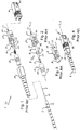
- FIG 5 is an exploded perspective view of an SC connector 101 according to the invention, in which features corresponding with those of Figures 1 to 4 are indicated with the same reference numerals.
- the connector 101 comprises an optical fibre cable 2, a ferrule housing sub-assembly 104, and an outer housing 40 to provide SC-style push/pull engagement/disengagement 46 with a mating optical fibre socket (not shown).
- the cable 2 holds a single strand of 125 ⁇ m diameter single mode optical fibre 8, protected by primary and secondary buffering layers 10, about 900 ⁇ m in diameter and an outer sheath 12, typically 3 mm to 5 mm in diameter.
- the optical fibre 8 is terminated by the ferrule in a manner well-known to those skilled in the art, and defines a ferrule axis 5 which extends centrally through the SC connector 101.
- the ferrule housing sub-assembly 104 includes a cylindrical ceramic ferrule 14, a ferrule holder 16 in which the ferrule is seated, a helical spring 17, a ferrule holder carrier 50 and an inner housing 120.
- the ferrule holder 16 has a cylindrical stem 22 which extends in an axial direction away from the ferrule 14 towards a sleeve 136 of the ferrule holder carrier 50 used to make a crimp connection around the optical fibre cable sheathing 12.
- the spring 17 is seated around the stem 22 between an annular shoulder 24 on the ferrule holder 16 and a similar annular surface 52 within a cylindrical recess 54 of the ferrule holder carrier 50.
- the stem 22 is slideably seated in a closely fitting bore 55 of the ferrule holder carrier.
- the carrier 50 has a pair of arms 56 around a portion of the stem 22 nearest the ferrule 14 which extend axially forwards of the stem on opposite sides of the base 15 of the ferrule holder.
- Two pairs of curved fingers 58 are provided, each pair extending in opposite circumferential directions at the end of each arm 56.
- the fingers 58 extend transversely to the length of the arms 56 partially around the circumference of a portion of the ferrule nearest the base 15.
- the ferrule base 15 has four cycles of crenellations 62 spaced symmetrically around the circumference of the base and which provide four corresponding channels that extend parallel to the optical fibre axis. These crenellations are in the form of alternating radially high 65 and low 66 cylindrically shaped regions with the circumferential and axial extent of each of the high and low regions being the same. The high and low regions are separated by steps 67 that extend in a radial direction.
- the arms 56 are seated in opposite radially low regions 66 in a sliding fit with the adjacent high regions 65, and reach axially forwards of the base 15 and crenellations 62 so that the fingers 58 engage with the intervening radially high regions 65 on a side 61 of the base 15 opposite the annular surface 24 against which the spring 17 is engaged.
- the arrangement permits a degree axial movement of the ferrule holder 50, with movement being therefore limited in one direction by the compression of the spring 17 between the two annular surfaces 24, 52 and in the other axial direction by the contact of the fingers 58 with the radially high regions 65 of the crenellations 62 on the base 15 of the ferrule holder 16.
- the ferrule holder base 15 and ferrule holder carrier 50 also have a common cylindrical outer envelope.
- the arrangement described above has the benefit of minimising the extent of the ferrule holder base 15 and ferrule holder carrier 50 in a radial direction so that this sub-assembly may be blown down a conduit or passed through other constricted spaces when installing an SC-type optical fibre communications link.
- the rotational orientation of the ferrule holder carrier 50 may be set at one of four orientations relative to the ferrule 14 in the ferrule holder 16 owing to the seating of the arms 56 in the crenellations. In this way, a first rotational key is provided between the ferrule holder 16 and the ferrule holder carrier 50.
- optical fibre 8 is therefore terminated in a sub-assembly referred to herein as an optical fibre connector sub-assembly 60.
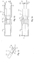
- an optical fibre connector sub-assembly 60 As can be appreciated by an inspection of Figures 8 to 10 , during assembly of the optical fibre connector sub-assembly 60 the arms 56 and fingers 58, which each have a chamfered taper 64 on an inner forwards surface, flex outwardly over the base 15 of the ferrule holder 14 until the fingers 58 snap radially inwards into engagement with the forwards surface 61 of the ferrule holder base 15.
- Figures 13 to 15 show various views of the ferrule holder carrier 50 described above.
- Figures 16 to 18 show similar views of a variant design of the ferrule holder carrier 150, which works in the same way as that described above, but which has a smaller diameter sleeve 236 over which an outer sheath 12 of the optical fibre cable may be crimped.
- the resulting optical fibre connector sub-assembly 60 is therefore mechanically whole or integral, both as regards the components forming the sub-assembly and as regards the mechanical connection of the sub-assembly to the optical fibre cable 2.
- the sub-assembly cannot come apart without first prising the fingers 58 back over the ferule holder base 15.
- the ferrule holder carrier has an outer diameter which is preferably no more than that of the widest portion of the ferrule holder 14, i.e. the ferrule holder base 15.
- the benefit of this arrangement is that the optical fibre connector sub-assembly 60 is thin enough in a radial direction to be inserted down a length of protective conduit 72, as shown in Figure 19 , even after first placing over the optical fibre connector sub-assembly 60 a temporary protective outer sleeve 74, in order to prevent damage to the optical fibre connector sub-assembly 60.
- the outer sleeve is preferably formed in a low friction material, such as PTFE, in order to facilitate smooth insertion of the sub-assembly down the length of conduit 72.
- the projecting end of the ferrule 14 may be additionally protected by a disposable end cap 76.
- an inner housing 120 is inserted in an axial direction over the projecting ferrule 14 and surrounding ferrule holder carrier 50.
- the ferrule holder carrier 50, 150 has an annular groove 78 within the cylindrical envelope defined by the radially outermost surfaces of the ferrule holder carrier.
- the inner housing has a pair of arms 80 each having at an end a radially inwardly projecting detent 82. The detents 82 are initially deflected radially outwards and then snap into engagement with the groove 78 as the inner housing is slid over the sub-assembly 60.
- This engagement prevents relative axial movement of the inner housing and the sub-assembly 60 in one direction.
- the advantage of this arrangement is that the groove 78 provides an engagement feature for the inner housing which does not add to the radial dimensions of the optical fibre connector sub-assembly, which makes it much easier to insert the sub-assembly down a narrow conduit or into other constricted spaces.
- the external shape of the inner housing 120 where this interacts with the outer housing 6 is the same as with the prior art.
- the outer housing therefore is snap-fitted over the inner housing, after which the SC-type connector 101 is fully compatible with the prior art connector 1.
- optical fibre connector sub-assembly can be adapted for use with other types of optical fibre connector systems, for example the ST-type connectors.
- the invention therefore provides a convenient optical fibre connector and optical fibre communication system and method for providing such a system.
Landscapes
- Physics & Mathematics (AREA)
- General Physics & Mathematics (AREA)
- Optics & Photonics (AREA)
- Mechanical Coupling Of Light Guides (AREA)
Claims (15)
- Faseroptische Verbinder-Teilanordnung (60) für einen faseroptischen Verbinder (101), umfassend eine optische Faser (8), eine zylindrische Zwinge (14), eine Zwingenhalterung (16), ein Federvorspannmittel (17) und einen Zwingenhalterungsträger (50), wobei:- die optische Faser in der Zwinge entlang einer Achse (5) der Zwinge gehalten wird, wobei die optische Faser an einer Stirnfläche (34) der Zwinge terminiert ist;- die Zwinge von der Zwingenhalterung gehalten wird;- die Zwingenhalterung mit einem Aufnahmeabschnitt (54) des Zwingenhalterungsträgers in Eingriff steht, wobei die Halterung und der Träger in Bezug zueinander entlang der Zwingenachse zwischen Grenzen, die durch eine Interaktion zwischen dem Zwingenhalterungsträger und der Zwingenhalterung definiert sind, relativ bewegbar sind, wobei ein Abschnitt der Zwinge, der zur Stirnfläche der Zwinge führt, entlang der Zwingenachse, weg vom Zwingenhalterungsträger, vorsteht;- das Federvorspannmittel (17) zwischen der Zwingenhalterung und dem Zwingenhalterungsträger bereitgestellt ist, sodass der vorstehende Abschnitt der Zwinge entlang der Zwingenachse, weg vom Zwingenhalterungsträger, federbelastet ist;- die Zwingenhalterung eine Basis (15) enthält, in welcher die Zwinge sitzt;- die Zwingenhalterungsbasis mehrere Krenelierungen (62) aufweist, die sich um den Umfang der Zwinge erstrecken, wobei der Zwingenhalterungsträger mindestens zwei getrennte Arme (52) aufweist, die sich in einer axialen Richtung durch die Krenelierungen zu der Zwinge erstrecken, wobei die Arme ein Bewegungsbegrenzungsmerkmal (58) enthalten, das mit der Zwingenhalterungsbasis interagiert, um die relative Bewegung der Zwingenhalterung und des Zwingenhalterungsträgers entlang einer Bewegungsrichtung entlang der Zwingenachse zu begrenzen.
- Faseroptische Verbinder-Teilanordnung (60) nach Anspruch 1, in welcher das Bewegungsbegrenzungsmerkmal aus einem oder mehreren vorstehenden Finger (58) an einem Ende der Arme (52) besteht.
- Faseroptische Verbinder-Teilanordnung (60) nach Anspruch 1, wobei das Bewegungsbegrenzungsmerkmal durch Merkmale (58) bereitgestellt ist, die die Arme (52) terminieren und die sich um den Umfang für einen Eingriff mit der Basis (15) erstrecken, um die relative Bewegung entlang der Zwingenachse (5) der Zwingenhalterung (16) weg vom Aufnahmeabschnitt (54) des Zwingenhalterungsträgers (50) zu begrenzen.
- Faseroptische Verbinder-Teilanordnung (60) nach Anspruch 1, in welcher das Bewegungsbegrenzungsmerkmal aus einem oder mehreren vorstehenden Fingern (58) besteht, die sich in einer Umfangsrichtung relativ zur Zwingenachse (5) erstrecken.
- Faseroptische Verbinder-Teilanordnung (60) nach einem vorangehenden Anspruch, in welcher das Bewegungsbegrenzungsmerkmal (58) mit einer Seite (61) der Krenelierungen (62) in Eingriff steht, die der Stirnfläche (34) der Zwinge (14) am nächsten liegt.
- Faseroptische Verbinder-Teilanordnung (60) nach Anspruch 5, in welcher die Krenelierungen (62) abwechselnd radial hohe (65) und tiefe (66) Regionen haben, wobei das Bewegungsbegrenzungsmerkmal mit einer radial hohen Region der Krenelierungen in Eingriff steht.
- Faseroptische Verbinder-Teilanordnung (60) nach Anspruch 5 oder Anspruch 6, wobei das Federvorspannmittel eine Schraubenfeder (17) ist, die zwischen der Zwingenhalterungsbasis (15) und dem Aufnahmeabschnitt (54) des Zwingenhalterungsträgers (50) bereitgestellt ist, wobei ein Ende der Schraubenfeder mit einer Seite (24) der Krenelierungen in Eingriff steht, die am weitesten von der Stirnfläche (34) der Zwinge entfernt ist.
- Faseroptische Verbinder-Teilanordnung (60) nach einem vorangehenden Anspruch, in welcher äußerste Oberflächen des Zwingenhalterungsträgers (50) und der Zwingenhalterung (16), relativ zur Zwingenachse (5), auf einer gemeinsam zylindrischen Ummantelung liegen.
- Faseroptische Verbinder-Teilanordnung (60) nach einem vorangehenden Anspruch, in welcher die Arme (52) gleitfähig mit den Krenelierungen (62) in Eingriff stehen.
- Faseroptische Verbinder-Teilanordnung (60) nach einem vorangehenden Anspruch, in welcher die Zwingenhalterung (16) und der Zwingenhalterungsträger (50) ausgebildet sind, durch einen Presspassvorgang montiert zu werden, in dem sich die Zwingenhalterung entlang der Zwingenachse (5) in den Aufnahmeabschnitt (54) des Zwingenhalterungsträgers (50) bewegt.
- Faseroptische Verbinder-Teilanordnung (60) nach einem vorangehenden Anspruch, in welcher die optische Faser (8) eine Länge einer optischen Faser enthält, die sich von der Zwinge (14), der Zwingenhalterung (16) und dem Zwingenhalterungsträger (50) weg erstreckt, wobei die Länge von einem Material zum Schutz und/oder zur Verstärkung umgeben ist, wobei der Zwingenhalterungsträger Mittel zum Befestigen einer Verkleidung an dem Material enthält.
- Verfahren zur Herstellung einer faseroptischen Verbindung unter Verwendung eines faseroptischen Verbinders (101) vom Subscriber Connection(SC)-Typ, wobei der Verbinder eine optische Faser (8), eine faseroptische Verbinder-Teilanordnung (60) und, um die Teilanordnung montiert, ein Innengehäuse (120) und ein Außengehäuse (40) umfasst, wobei das Innengehäuse (120) ein radial nach innen vorstehendes Merkmal (82) aufweist, wobei das Verfahren die Schritte umfasst:- Terminieren der optischen Faser an einer Stirnfläche (34) einer Zwinge (14);- Verwenden einer Zwingenhalterung (16) zum Halten der Zwinge, sodass sich die Zwinge von der Zwingenhalterung weg zur Stirnfläche erstreckt;- In-Eingriff-Bringen der Zwingenhalterung in einem Aufnahmeabschnitt (54) eines Zwingenhalterungsträgers (50) und Anordnen eines Federvorspannmittels (17) zwischen der Zwingenhalterung und dem Zwingenhalterungsträger, um die Teilanordnung zu bilden, sodass die Halterung und der Träger auseinander federbelastet sind und in Bezug zueinander entlang einer Zwingenachse (5) zwischen Grenzen, die durch eine Interaktion zwischen dem Zwingenhalterungsträger und der Zwingenhalterung definiert sind, relativ bewegbar sind, und sodass radial äußerste Oberflächen der Teilanordnung eine zylindrische Ummantelung der Teilanordnung definieren, wobei der Zwingenhalterungsträger eine Rille (78) in der Ummantelung aufweist;- Einsetzen der faseroptischen Verbinder-Teilanordnung in eine Länge einer Schutzleitung;- nach dem Einsetzen, Montieren des Innengehäuses (120) an der Teilanordnung (60), durch In-Eingriff-Bringen des Innengehäuses mit der Teilanordnung, während sich das radial nach innen vorstehende Merkmal (82) in der Rille (78) befindet, und dann Bilden eines faseroptischen Verbinders (101) vom SC-Typ durch In-Eingriff-Bringen des Außengehäuses (40) um das Innengehäuse (120), wobei das Innen- und Außengehäuse relativ zu einander bewegbar sind, um eine Eingriffs-/Lösefunktionalität durch Schieben/Ziehen im SC-Stil bereitzustellen; und- Zusammenpassen des faseroptischen Verbinders (101) vom SC-Typ mit einer passenden Buchse für eine optische Faser.
- Verfahren nach Anspruch 12, wobei die Rille eine ringförmige Rille (78) ist und das radial nach innen vorstehende Merkmal eine radial nach innen vorstehende Arretierung (82) ist, wobei während des Eingriffs des Innengehäuses (120) mit der Teilanordnung (60) die Arretierung zunächst radial nach außen abgelenkt wird und dann radial nach innen in Eingriff mit der Rille schnappt, wenn das Innengehäuse über die Teilanordnung geschoben wird.
- Verfahren nach Anspruch 12 oder Anspruch 13, wobei das Verfahren ein Anordnen einer provisorischen schützenden Außenhülse (74) über der gesamten faseroptischen Verbinder-Teilanordnung (60) vor dem Einsetzen der faseroptischen Verbinder-Teilanordnung in die Länge der Schutzleitung umfasst, und dann ein Entfernen der Außenhülse nach dem Einsetzen und vor dem Montieren des Innengehäuses (120) an der Teilanordnung.
- Verfahren nach Anspruch 14, umfassend ein Anordnen einer provisorischen Endkappe (76) über dem vorstehenden Ende der Zwinge (14) vor dem Einsetzen der faseroptischen Verbinder-Teilanordnung (60) in die Länge der Schutzleitung und dann Entfernen der Endkappe nach dem Einsetzen und vor dem Montieren des Innengehäuses (120) an der Teilanordnung.
Priority Applications (2)
| Application Number | Priority Date | Filing Date | Title |
|---|---|---|---|
| DK16195321.1T DK3141940T3 (en) | 2007-05-04 | 2008-04-30 | Optical fibre connector |
| EP16195321.1A EP3141940B1 (de) | 2007-05-04 | 2008-04-30 | Faseroptischer stecker |
Applications Claiming Priority (2)
| Application Number | Priority Date | Filing Date | Title |
|---|---|---|---|
| GB0708709A GB2448935B8 (en) | 2007-05-04 | 2007-05-04 | Opticle fibre connector |
| PCT/GB2008/001505 WO2008135727A2 (en) | 2007-05-04 | 2008-04-30 | Optical fibre connector |
Related Child Applications (2)
| Application Number | Title | Priority Date | Filing Date |
|---|---|---|---|
| EP16195321.1A Division EP3141940B1 (de) | 2007-05-04 | 2008-04-30 | Faseroptischer stecker |
| EP16195321.1A Division-Into EP3141940B1 (de) | 2007-05-04 | 2008-04-30 | Faseroptischer stecker |
Publications (2)
| Publication Number | Publication Date |
|---|---|
| EP2145221A2 EP2145221A2 (de) | 2010-01-20 |
| EP2145221B1 true EP2145221B1 (de) | 2018-01-31 |
Family
ID=38198795
Family Applications (2)
| Application Number | Title | Priority Date | Filing Date |
|---|---|---|---|
| EP16195321.1A Active EP3141940B1 (de) | 2007-05-04 | 2008-04-30 | Faseroptischer stecker |
| EP08737141.5A Active EP2145221B1 (de) | 2007-05-04 | 2008-04-30 | Faseroptischer verbinder |
Family Applications Before (1)
| Application Number | Title | Priority Date | Filing Date |
|---|---|---|---|
| EP16195321.1A Active EP3141940B1 (de) | 2007-05-04 | 2008-04-30 | Faseroptischer stecker |
Country Status (5)
| Country | Link |
|---|---|
| US (1) | US8439577B2 (de) |
| EP (2) | EP3141940B1 (de) |
| DK (1) | DK3141940T3 (de) |
| GB (1) | GB2448935B8 (de) |
| WO (1) | WO2008135727A2 (de) |
Families Citing this family (62)
| Publication number | Priority date | Publication date | Assignee | Title |
|---|---|---|---|---|
| EP2293129B1 (de) * | 2009-09-03 | 2012-12-05 | Tyco Electronics Raychem BVBA | Glasfaserverbinderanordnung und Faserabschlusseinheit |
| GB2483498A (en) | 2010-09-10 | 2012-03-14 | Miniflex Ltd | A water-resistant optical fibre connector with an elastomer sleeve providing both a water seal and a coupling force |
| JP2013142858A (ja) * | 2012-01-12 | 2013-07-22 | Hitachi Cable Ltd | フェルール保持部材及び光コネクタ |
| US9297976B2 (en) * | 2012-11-14 | 2016-03-29 | Clearfield, Inc. | Optical fiber connector |
| BR112015011507A2 (pt) | 2012-11-30 | 2017-07-11 | Tyco Electronics Corp | configuração dividida distribuída para unidade multidomiciliar |
| WO2014085462A1 (en) | 2012-11-30 | 2014-06-05 | Tyco Electronics Corporation | Fiber optic connector with field installable outer connector housing |
| CN104678514B (zh) * | 2013-11-29 | 2017-01-04 | 台达电子工业股份有限公司 | 光收发模块 |
| GB201400687D0 (en) * | 2014-01-15 | 2014-03-05 | Eden Ltd | Connecting device for a cable housing arrangement |
| CN104849815B (zh) | 2014-02-14 | 2017-01-18 | 泰科电子(上海)有限公司 | 光纤连接器及其组装方法 |
| CN104849816B (zh) | 2014-02-14 | 2017-01-11 | 泰科电子(上海)有限公司 | 光纤连接器及其组装方法 |
| CN105445862B (zh) | 2014-07-09 | 2018-01-19 | 泰科电子(上海)有限公司 | 光纤连接器及其现场组装方法 |
| EP3177952B1 (de) * | 2014-08-06 | 2020-11-18 | Prysmian S.p.A. | Glasfaserverbinderanordnung |
| US9383527B2 (en) | 2014-08-13 | 2016-07-05 | Rolling River, LLC | Optical connector suitable for field assembly |
| USD734132S1 (en) | 2014-08-13 | 2015-07-14 | Rolling River, LLC | Optical connector assembly jig |
| WO2016095213A1 (en) * | 2014-12-19 | 2016-06-23 | Tyco Electronics (Shanghai) Co., Ltd. | Hardened fiber optic connector with pre-compressed spring |
| US9581768B1 (en) * | 2015-08-21 | 2017-02-28 | Corning Optical Communications LLC | Fiber optic connector sub-assemblies and related methods |
| EP4403972A3 (de) * | 2015-11-30 | 2024-10-16 | CommScope Technologies LLC | Faseroptischer verbinder und dessen zusammenbau |
| EP3391115A4 (de) | 2015-12-16 | 2019-07-17 | Commscope Technologies LLC | Am einsatzort installierter glasfaserverbinder |
| WO2017124018A1 (en) | 2016-01-14 | 2017-07-20 | Communications Systems, Inc. | Stackable splitters |
| US10606006B2 (en) * | 2016-09-20 | 2020-03-31 | Clearfield, Inc. | Optical fiber distribution systems and components |
| US10859781B2 (en) | 2016-09-20 | 2020-12-08 | Clearfield, Inc. | Optical fiber distribution systems and components |
| US9927581B1 (en) * | 2016-10-28 | 2018-03-27 | Corning Optical Communications LLC | Connector tuning method and ferrule for fiber optic cable assemblies |
| CN110031939B (zh) * | 2016-12-05 | 2020-06-09 | 扇港元器件股份有限公司 | 具有模块化闩锁臂的窄宽度适配器和连接器 |
| CN108614327B (zh) * | 2016-12-09 | 2019-08-30 | 林雨晴 | 光纤连接器 |
| WO2018142213A1 (en) | 2017-02-02 | 2018-08-09 | Ppc Broadband Fiber Ltd. | Optical fiber connector |
| CA3063107A1 (en) * | 2017-05-11 | 2018-11-15 | Ppc Broadband, Inc. | Pushable optical connector with connector-integrated articulation |
| US11585987B2 (en) * | 2017-05-11 | 2023-02-21 | Ppc Broadband, Inc. | Pushable optical connector with connector-integrated articulation |
| US12271040B2 (en) | 2017-06-28 | 2025-04-08 | Corning Research & Development Corporation | Fiber optic extender ports, assemblies and methods of making the same |
| US11300746B2 (en) | 2017-06-28 | 2022-04-12 | Corning Research & Development Corporation | Fiber optic port module inserts, assemblies and methods of making the same |
| US11187859B2 (en) | 2017-06-28 | 2021-11-30 | Corning Research & Development Corporation | Fiber optic connectors and methods of making the same |
| US10359577B2 (en) | 2017-06-28 | 2019-07-23 | Corning Research & Development Corporation | Multiports and optical connectors with rotationally discrete locking and keying features |
| EP3646092B1 (de) | 2017-06-28 | 2021-11-24 | Corning Research & Development Corporation | Kompakte glasfaserverbinder |
| US11668890B2 (en) | 2017-06-28 | 2023-06-06 | Corning Research & Development Corporation | Multiports and other devices having optical connection ports with securing features and methods of making the same |
| AU2018360319B2 (en) * | 2017-11-06 | 2024-08-29 | Ppc Broadband Fiber Ltd. | Shroud for SC optical connector |
| US10324262B1 (en) | 2017-12-07 | 2019-06-18 | Wei Min Wang | Field terminable fiber optic connectors |
| WO2019183034A1 (en) | 2018-03-20 | 2019-09-26 | Commscope Technologies Llc | Fiber optic cable terminal with a pushable stub cable |
| WO2020028920A1 (en) * | 2018-08-03 | 2020-02-06 | Ppc Broadband, Inc. | Fiber optical connector with retention feature |
| US12504586B2 (en) | 2018-08-03 | 2025-12-23 | Ppc Broadband, Inc. | Fiber optical connectors |
| MX2021006211A (es) | 2018-11-29 | 2021-08-11 | Corning Res & Dev Corp | Multipuertos y otros dispositivos que tienen puertos de conexion optica con accionadores giratorios y metodos de fabricacion de los mismos. |
| AU2020207399B2 (en) * | 2019-01-10 | 2025-11-20 | Ppc Broadband, Inc. | Fiber optical connector |
| US11422312B2 (en) * | 2019-05-09 | 2022-08-23 | Commscope Technologies Llc | Fiber optic converter |
| MX2021014427A (es) | 2019-05-31 | 2022-03-04 | Corning Res & Dev Corp | Multipuertos y otros dispositivos que tienen puertos de conexion optica con accionadores deslizantes y metodos para elaborar los mismos. |
| US11294133B2 (en) | 2019-07-31 | 2022-04-05 | Corning Research & Development Corporation | Fiber optic networks using multiports and cable assemblies with cable-to-connector orientation |
| EP3805827B1 (de) | 2019-10-07 | 2025-07-30 | Corning Research & Development Corporation | Faseroptische anschlüsse und faseroptische netzwerke mit kopplern mit variablem verhältnis |
| EP4045957B1 (de) | 2019-10-18 | 2023-12-13 | Corning Research & Development Corporation | Anschlüsse mit optischen anschlussöffnungen mit befestigungsmerkmalen zur bereitstellung stabiler haltekräfte |
| US11650388B2 (en) | 2019-11-14 | 2023-05-16 | Corning Research & Development Corporation | Fiber optic networks having a self-supporting optical terminal and methods of installing the optical terminal |
| CN115053162B (zh) | 2019-12-10 | 2025-05-09 | Ppc宽带股份有限公司 | 具有电缆保持特征的机械连接器 |
| US11966088B2 (en) * | 2020-01-17 | 2024-04-23 | Ppc Broadband Fiber Ltd. | Optical fiber connectors |
| WO2021144653A1 (en) | 2020-01-17 | 2021-07-22 | Ppc Broadband Fiber Ltd. | Optical fiber connectors |
| US11536921B2 (en) | 2020-02-11 | 2022-12-27 | Corning Research & Development Corporation | Fiber optic terminals having one or more loopback assemblies |
| US11846810B2 (en) | 2020-05-28 | 2023-12-19 | Corning Research & Development Corporation | Cable adapters with integrated seal, optical connectors, optical cable assemblies, and methods of fabricating the same |
| CA3184578A1 (en) | 2020-06-29 | 2022-01-06 | Michael De Jong | Terminals having a multi-fiber optical connection port that inhibits damage from single-fiber connectors |
| US11604320B2 (en) | 2020-09-30 | 2023-03-14 | Corning Research & Development Corporation | Connector assemblies for telecommunication enclosures |
| CN116601834A (zh) | 2020-10-30 | 2023-08-15 | 康宁研究与开发公司 | 具有防风雨套环的光纤连接器 |
| US11994722B2 (en) | 2020-11-30 | 2024-05-28 | Corning Research & Development Corporation | Fiber optic adapter assemblies including an adapter housing and a locking housing |
| US11686913B2 (en) | 2020-11-30 | 2023-06-27 | Corning Research & Development Corporation | Fiber optic cable assemblies and connector assemblies having a crimp ring and crimp body and methods of fabricating the same |
| US11927810B2 (en) | 2020-11-30 | 2024-03-12 | Corning Research & Development Corporation | Fiber optic adapter assemblies including a conversion housing and a release member |
| US11880076B2 (en) | 2020-11-30 | 2024-01-23 | Corning Research & Development Corporation | Fiber optic adapter assemblies including a conversion housing and a release housing |
| WO2022215060A1 (en) * | 2021-04-09 | 2022-10-13 | Ppc Broadband Fiber Ltd. | Optical fiber connector |
| TWM617264U (zh) | 2021-04-12 | 2021-09-21 | 連訊通信股份有限公司 | 光纖連接器 |
| US11947167B2 (en) | 2021-05-26 | 2024-04-02 | Corning Research & Development Corporation | Fiber optic terminals and tools and methods for adjusting a split ratio of a fiber optic terminal |
| US12197018B2 (en) | 2021-06-30 | 2025-01-14 | Ppc Broadband, Inc. | Fiber optic connector retention assembly |
Family Cites Families (19)
| Publication number | Priority date | Publication date | Assignee | Title |
|---|---|---|---|---|
| JP2504852B2 (ja) * | 1990-03-02 | 1996-06-05 | 日本電信電話株式会社 | 光コネクタプラグ |
| US5253315A (en) * | 1990-12-24 | 1993-10-12 | Fentress Vernon A | Method and apparatus for installing a fiber optic cable by capture of a coupling nut or coupling nut assembly |
| US5212752A (en) * | 1992-05-27 | 1993-05-18 | At&T Bell Laboratories | Optical fiber ferrule connector having enhanced provisions for tuning |
| US5287425A (en) * | 1993-02-26 | 1994-02-15 | Foxconn International, Inc. | Optical fiber SC type connector assembly with partly pre-assembled components |
| EP0766838B1 (de) * | 1994-06-22 | 2002-03-06 | The Whitaker Corporation | Faseroptischer stecker mit verbesserten mitteln zum zusammenbau |
| GB2292467A (en) * | 1994-08-19 | 1996-02-21 | Itt Ind Ltd | Optical fibre connector ferrule holder with tines |
| JPH1138276A (ja) * | 1997-07-22 | 1999-02-12 | Seiko Giken:Kk | 光コネクタの構造およびその調心方法 |
| JP3641201B2 (ja) * | 2000-10-31 | 2005-04-20 | 三和電気工業株式会社 | 光コネクタプラグ |
| US6428215B1 (en) * | 2000-12-27 | 2002-08-06 | Adc Telecommunications, Inc. | Tunable fiber optic connector and method for assembling |
| US6783281B2 (en) * | 2002-08-13 | 2004-08-31 | Hon Hai Precision Ind. Co., Ltd. | Optical fiber converter retaining different sized ferrules |
| US6918704B2 (en) * | 2003-01-30 | 2005-07-19 | Panduit Corp. | Tunable fiber optic connector |
| US7011454B2 (en) * | 2003-08-25 | 2006-03-14 | Panduit Corp. | Reversible fiber optic stub fiber connector |
| US7204644B2 (en) * | 2004-03-24 | 2007-04-17 | Corning Cable Systems Llc | Field installable optical fiber connector |
| US7201518B2 (en) * | 2004-04-14 | 2007-04-10 | Adc Telecommunications, Inc. | Fiber optic connector and method |
| JP2005301151A (ja) * | 2004-04-15 | 2005-10-27 | Canare Electric Co Ltd | 光コンタクトユニット及び光プラグ |
| JP2005309028A (ja) * | 2004-04-21 | 2005-11-04 | Jeol Ltd | 光ファイバコネクタ及び試料観察装置 |
| KR100507543B1 (ko) * | 2004-06-30 | 2005-08-09 | 주식회사 골드텔 | 광커넥터 |
| JP2006184271A (ja) * | 2004-12-01 | 2006-07-13 | Kyocera Corp | コア偏心測定方法とコア偏心測定装置およびそれを用いた光コネクタプラグの製造方法 |
| US7241056B1 (en) * | 2006-06-13 | 2007-07-10 | Panduit Corp. | Reversible fiber optic connector |
-
2007
- 2007-05-04 GB GB0708709A patent/GB2448935B8/en active Active
-
2008
- 2008-04-30 WO PCT/GB2008/001505 patent/WO2008135727A2/en not_active Ceased
- 2008-04-30 EP EP16195321.1A patent/EP3141940B1/de active Active
- 2008-04-30 DK DK16195321.1T patent/DK3141940T3/da active
- 2008-04-30 US US12/598,822 patent/US8439577B2/en active Active
- 2008-04-30 EP EP08737141.5A patent/EP2145221B1/de active Active
Also Published As
| Publication number | Publication date |
|---|---|
| US8439577B2 (en) | 2013-05-14 |
| EP3141940B1 (de) | 2024-01-24 |
| DK3141940T3 (en) | 2024-04-29 |
| EP2145221A2 (de) | 2010-01-20 |
| EP3141940A1 (de) | 2017-03-15 |
| GB0708709D0 (en) | 2007-06-13 |
| US20100215321A1 (en) | 2010-08-26 |
| WO2008135727A3 (en) | 2009-01-29 |
| GB2448935A (en) | 2008-11-05 |
| GB2448935B8 (en) | 2010-08-25 |
| GB2448935B (en) | 2010-08-04 |
| WO2008135727A2 (en) | 2008-11-13 |
Similar Documents
| Publication | Publication Date | Title |
|---|---|---|
| EP2145221B1 (de) | Faseroptischer verbinder | |
| US12140805B2 (en) | Optical fiber connector with articulated relative movement | |
| EP3622337B1 (de) | Steckbarer optischer steckverbinder mit verbinderintegriertem gelenk | |
| US10564368B2 (en) | Optical fiber connector assembly | |
| US11966088B2 (en) | Optical fiber connectors | |
| US12055767B2 (en) | Pushable optical connector with connector-integrated articulation | |
| US11650376B2 (en) | Optical fiber connectors | |
| GB2468442A (en) | Method of installing a Subscriber Connection (SC) optical fibre connector | |
| EP4341736A1 (de) | Anordnungen zum ziehen, schieben oder blasen mehrerer glasfaserkabel durch einen kanal | |
| EP4091007B1 (de) | Vorkonfektionierte mehrfaserige verbindungskabel | |
| WO2022215060A1 (en) | Optical fiber connector |
Legal Events
| Date | Code | Title | Description |
|---|---|---|---|
| PUAI | Public reference made under article 153(3) epc to a published international application that has entered the european phase |
Free format text: ORIGINAL CODE: 0009012 |
|
| 17P | Request for examination filed |
Effective date: 20091030 |
|
| AK | Designated contracting states |
Kind code of ref document: A2 Designated state(s): AT BE BG CH CY CZ DE DK EE ES FI FR GB GR HR HU IE IS IT LI LT LU LV MC MT NL NO PL PT RO SE SI SK TR |
|
| AX | Request for extension of the european patent |
Extension state: AL BA MK RS |
|
| DAX | Request for extension of the european patent (deleted) | ||
| GRAJ | Information related to disapproval of communication of intention to grant by the applicant or resumption of examination proceedings by the epo deleted |
Free format text: ORIGINAL CODE: EPIDOSDIGR1 |
|
| GRAP | Despatch of communication of intention to grant a patent |
Free format text: ORIGINAL CODE: EPIDOSNIGR1 |
|
| GRAP | Despatch of communication of intention to grant a patent |
Free format text: ORIGINAL CODE: EPIDOSNIGR1 |
|
| INTG | Intention to grant announced |
Effective date: 20160722 |
|
| RAP1 | Party data changed (applicant data changed or rights of an application transferred) |
Owner name: PPC BROADBAND FIBER LTD. |
|
| GRAJ | Information related to disapproval of communication of intention to grant by the applicant or resumption of examination proceedings by the epo deleted |
Free format text: ORIGINAL CODE: EPIDOSDIGR1 |
|
| INTC | Intention to grant announced (deleted) | ||
| RIN1 | Information on inventor provided before grant (corrected) |
Inventor name: JENKINS, PETER, DAVID |
|
| GRAP | Despatch of communication of intention to grant a patent |
Free format text: ORIGINAL CODE: EPIDOSNIGR1 |
|
| STAA | Information on the status of an ep patent application or granted ep patent |
Free format text: STATUS: GRANT OF PATENT IS INTENDED |
|
| INTG | Intention to grant announced |
Effective date: 20170207 |
|
| GRAJ | Information related to disapproval of communication of intention to grant by the applicant or resumption of examination proceedings by the epo deleted |
Free format text: ORIGINAL CODE: EPIDOSDIGR1 |
|
| STAA | Information on the status of an ep patent application or granted ep patent |
Free format text: STATUS: REQUEST FOR EXAMINATION WAS MADE |
|
| INTC | Intention to grant announced (deleted) | ||
| GRAP | Despatch of communication of intention to grant a patent |
Free format text: ORIGINAL CODE: EPIDOSNIGR1 |
|
| STAA | Information on the status of an ep patent application or granted ep patent |
Free format text: STATUS: GRANT OF PATENT IS INTENDED |
|
| INTG | Intention to grant announced |
Effective date: 20170818 |
|
| GRAS | Grant fee paid |
Free format text: ORIGINAL CODE: EPIDOSNIGR3 |
|
| GRAA | (expected) grant |
Free format text: ORIGINAL CODE: 0009210 |
|
| STAA | Information on the status of an ep patent application or granted ep patent |
Free format text: STATUS: THE PATENT HAS BEEN GRANTED |
|
| RBV | Designated contracting states (corrected) |
Designated state(s): AT BE BG CH CY CZ DE DK EE ES FI FR GR HR HU IE IS IT LI LT LU LV MC MT NL NO PL PT RO SE SI SK TR |
|
| AK | Designated contracting states |
Kind code of ref document: B1 Designated state(s): AT BE BG CH CY CZ DE DK EE ES FI FR GR HR HU IE IS IT LI LT LU LV MC MT NL NO PL PT RO SE SI SK TR |
|
| REG | Reference to a national code |
Ref country code: CH Ref legal event code: EP |
|
| REG | Reference to a national code |
Ref country code: AT Ref legal event code: REF Ref document number: 967899 Country of ref document: AT Kind code of ref document: T Effective date: 20180215 |
|
| REG | Reference to a national code |
Ref country code: IE Ref legal event code: FG4D |
|
| REG | Reference to a national code |
Ref country code: DE Ref legal event code: R096 Ref document number: 602008053919 Country of ref document: DE |
|
| REG | Reference to a national code |
Ref country code: FR Ref legal event code: PLFP Year of fee payment: 11 |
|
| REG | Reference to a national code |
Ref country code: NL Ref legal event code: FP |
|
| REG | Reference to a national code |
Ref country code: LT Ref legal event code: MG4D |
|
| REG | Reference to a national code |
Ref country code: AT Ref legal event code: MK05 Ref document number: 967899 Country of ref document: AT Kind code of ref document: T Effective date: 20180131 |
|
| PG25 | Lapsed in a contracting state [announced via postgrant information from national office to epo] |
Ref country code: LT Free format text: LAPSE BECAUSE OF FAILURE TO SUBMIT A TRANSLATION OF THE DESCRIPTION OR TO PAY THE FEE WITHIN THE PRESCRIBED TIME-LIMIT Effective date: 20180131 Ref country code: HR Free format text: LAPSE BECAUSE OF FAILURE TO SUBMIT A TRANSLATION OF THE DESCRIPTION OR TO PAY THE FEE WITHIN THE PRESCRIBED TIME-LIMIT Effective date: 20180131 Ref country code: ES Free format text: LAPSE BECAUSE OF FAILURE TO SUBMIT A TRANSLATION OF THE DESCRIPTION OR TO PAY THE FEE WITHIN THE PRESCRIBED TIME-LIMIT Effective date: 20180131 Ref country code: NO Free format text: LAPSE BECAUSE OF FAILURE TO SUBMIT A TRANSLATION OF THE DESCRIPTION OR TO PAY THE FEE WITHIN THE PRESCRIBED TIME-LIMIT Effective date: 20180430 Ref country code: FI Free format text: LAPSE BECAUSE OF FAILURE TO SUBMIT A TRANSLATION OF THE DESCRIPTION OR TO PAY THE FEE WITHIN THE PRESCRIBED TIME-LIMIT Effective date: 20180131 |
|
| PG25 | Lapsed in a contracting state [announced via postgrant information from national office to epo] |
Ref country code: PL Free format text: LAPSE BECAUSE OF FAILURE TO SUBMIT A TRANSLATION OF THE DESCRIPTION OR TO PAY THE FEE WITHIN THE PRESCRIBED TIME-LIMIT Effective date: 20180131 Ref country code: AT Free format text: LAPSE BECAUSE OF FAILURE TO SUBMIT A TRANSLATION OF THE DESCRIPTION OR TO PAY THE FEE WITHIN THE PRESCRIBED TIME-LIMIT Effective date: 20180131 Ref country code: GR Free format text: LAPSE BECAUSE OF FAILURE TO SUBMIT A TRANSLATION OF THE DESCRIPTION OR TO PAY THE FEE WITHIN THE PRESCRIBED TIME-LIMIT Effective date: 20180501 Ref country code: SE Free format text: LAPSE BECAUSE OF FAILURE TO SUBMIT A TRANSLATION OF THE DESCRIPTION OR TO PAY THE FEE WITHIN THE PRESCRIBED TIME-LIMIT Effective date: 20180131 Ref country code: LV Free format text: LAPSE BECAUSE OF FAILURE TO SUBMIT A TRANSLATION OF THE DESCRIPTION OR TO PAY THE FEE WITHIN THE PRESCRIBED TIME-LIMIT Effective date: 20180131 Ref country code: BG Free format text: LAPSE BECAUSE OF FAILURE TO SUBMIT A TRANSLATION OF THE DESCRIPTION OR TO PAY THE FEE WITHIN THE PRESCRIBED TIME-LIMIT Effective date: 20180430 Ref country code: IS Free format text: LAPSE BECAUSE OF FAILURE TO SUBMIT A TRANSLATION OF THE DESCRIPTION OR TO PAY THE FEE WITHIN THE PRESCRIBED TIME-LIMIT Effective date: 20180531 |
|
| PG25 | Lapsed in a contracting state [announced via postgrant information from national office to epo] |
Ref country code: RO Free format text: LAPSE BECAUSE OF FAILURE TO SUBMIT A TRANSLATION OF THE DESCRIPTION OR TO PAY THE FEE WITHIN THE PRESCRIBED TIME-LIMIT Effective date: 20180131 Ref country code: EE Free format text: LAPSE BECAUSE OF FAILURE TO SUBMIT A TRANSLATION OF THE DESCRIPTION OR TO PAY THE FEE WITHIN THE PRESCRIBED TIME-LIMIT Effective date: 20180131 Ref country code: IT Free format text: LAPSE BECAUSE OF FAILURE TO SUBMIT A TRANSLATION OF THE DESCRIPTION OR TO PAY THE FEE WITHIN THE PRESCRIBED TIME-LIMIT Effective date: 20180131 |
|
| REG | Reference to a national code |
Ref country code: DE Ref legal event code: R097 Ref document number: 602008053919 Country of ref document: DE |
|
| PG25 | Lapsed in a contracting state [announced via postgrant information from national office to epo] |
Ref country code: SK Free format text: LAPSE BECAUSE OF FAILURE TO SUBMIT A TRANSLATION OF THE DESCRIPTION OR TO PAY THE FEE WITHIN THE PRESCRIBED TIME-LIMIT Effective date: 20180131 Ref country code: CZ Free format text: LAPSE BECAUSE OF FAILURE TO SUBMIT A TRANSLATION OF THE DESCRIPTION OR TO PAY THE FEE WITHIN THE PRESCRIBED TIME-LIMIT Effective date: 20180131 Ref country code: DK Free format text: LAPSE BECAUSE OF FAILURE TO SUBMIT A TRANSLATION OF THE DESCRIPTION OR TO PAY THE FEE WITHIN THE PRESCRIBED TIME-LIMIT Effective date: 20180131 Ref country code: MC Free format text: LAPSE BECAUSE OF FAILURE TO SUBMIT A TRANSLATION OF THE DESCRIPTION OR TO PAY THE FEE WITHIN THE PRESCRIBED TIME-LIMIT Effective date: 20180131 |
|
| REG | Reference to a national code |
Ref country code: CH Ref legal event code: PL |
|
| PLBE | No opposition filed within time limit |
Free format text: ORIGINAL CODE: 0009261 |
|
| STAA | Information on the status of an ep patent application or granted ep patent |
Free format text: STATUS: NO OPPOSITION FILED WITHIN TIME LIMIT |
|
| REG | Reference to a national code |
Ref country code: BE Ref legal event code: MM Effective date: 20180430 |
|
| 26N | No opposition filed |
Effective date: 20181102 |
|
| REG | Reference to a national code |
Ref country code: IE Ref legal event code: MM4A |
|
| PG25 | Lapsed in a contracting state [announced via postgrant information from national office to epo] |
Ref country code: LU Free format text: LAPSE BECAUSE OF NON-PAYMENT OF DUE FEES Effective date: 20180430 |
|
| PG25 | Lapsed in a contracting state [announced via postgrant information from national office to epo] |
Ref country code: BE Free format text: LAPSE BECAUSE OF NON-PAYMENT OF DUE FEES Effective date: 20180430 Ref country code: SI Free format text: LAPSE BECAUSE OF FAILURE TO SUBMIT A TRANSLATION OF THE DESCRIPTION OR TO PAY THE FEE WITHIN THE PRESCRIBED TIME-LIMIT Effective date: 20180131 Ref country code: CH Free format text: LAPSE BECAUSE OF NON-PAYMENT OF DUE FEES Effective date: 20180430 Ref country code: LI Free format text: LAPSE BECAUSE OF NON-PAYMENT OF DUE FEES Effective date: 20180430 |
|
| PG25 | Lapsed in a contracting state [announced via postgrant information from national office to epo] |
Ref country code: IE Free format text: LAPSE BECAUSE OF NON-PAYMENT OF DUE FEES Effective date: 20180430 |
|
| PG25 | Lapsed in a contracting state [announced via postgrant information from national office to epo] |
Ref country code: MT Free format text: LAPSE BECAUSE OF NON-PAYMENT OF DUE FEES Effective date: 20180430 |
|
| PG25 | Lapsed in a contracting state [announced via postgrant information from national office to epo] |
Ref country code: TR Free format text: LAPSE BECAUSE OF FAILURE TO SUBMIT A TRANSLATION OF THE DESCRIPTION OR TO PAY THE FEE WITHIN THE PRESCRIBED TIME-LIMIT Effective date: 20180131 |
|
| PG25 | Lapsed in a contracting state [announced via postgrant information from national office to epo] |
Ref country code: HU Free format text: LAPSE BECAUSE OF FAILURE TO SUBMIT A TRANSLATION OF THE DESCRIPTION OR TO PAY THE FEE WITHIN THE PRESCRIBED TIME-LIMIT; INVALID AB INITIO Effective date: 20080430 Ref country code: PT Free format text: LAPSE BECAUSE OF FAILURE TO SUBMIT A TRANSLATION OF THE DESCRIPTION OR TO PAY THE FEE WITHIN THE PRESCRIBED TIME-LIMIT Effective date: 20180131 |
|
| PG25 | Lapsed in a contracting state [announced via postgrant information from national office to epo] |
Ref country code: CY Free format text: LAPSE BECAUSE OF FAILURE TO SUBMIT A TRANSLATION OF THE DESCRIPTION OR TO PAY THE FEE WITHIN THE PRESCRIBED TIME-LIMIT Effective date: 20180131 |
|
| P01 | Opt-out of the competence of the unified patent court (upc) registered |
Effective date: 20230527 |
|
| PGFP | Annual fee paid to national office [announced via postgrant information from national office to epo] |
Ref country code: NL Payment date: 20250427 Year of fee payment: 18 |
|
| PGFP | Annual fee paid to national office [announced via postgrant information from national office to epo] |
Ref country code: DE Payment date: 20250429 Year of fee payment: 18 |
|
| PGFP | Annual fee paid to national office [announced via postgrant information from national office to epo] |
Ref country code: FR Payment date: 20250425 Year of fee payment: 18 |