EP2145376B1 - Verfahren zur herstellung eines rotors für eine rotierende elektrische maschine, insbesondere einen generator - Google Patents
Verfahren zur herstellung eines rotors für eine rotierende elektrische maschine, insbesondere einen generator Download PDFInfo
- Publication number
- EP2145376B1 EP2145376B1 EP08805693.2A EP08805693A EP2145376B1 EP 2145376 B1 EP2145376 B1 EP 2145376B1 EP 08805693 A EP08805693 A EP 08805693A EP 2145376 B1 EP2145376 B1 EP 2145376B1
- Authority
- EP
- European Patent Office
- Prior art keywords
- rotary
- rotor
- rotary field
- angular
- indexing
- Prior art date
- Legal status (The legal status is an assumption and is not a legal conclusion. Google has not performed a legal analysis and makes no representation as to the accuracy of the status listed.)
- Active
Links
Images


Classifications
-
- H—ELECTRICITY
- H02—GENERATION; CONVERSION OR DISTRIBUTION OF ELECTRIC POWER
- H02K—DYNAMO-ELECTRIC MACHINES
- H02K21/00—Synchronous motors having permanent magnets; Synchronous generators having permanent magnets
- H02K21/02—Details
- H02K21/04—Windings on magnets for additional excitation ; Windings and magnets for additional excitation
- H02K21/042—Windings on magnets for additional excitation ; Windings and magnets for additional excitation with permanent magnets and field winding both rotating
- H02K21/044—Rotor of the claw pole type
-
- H—ELECTRICITY
- H02—GENERATION; CONVERSION OR DISTRIBUTION OF ELECTRIC POWER
- H02K—DYNAMO-ELECTRIC MACHINES
- H02K15/00—Processes or apparatus specially adapted for manufacturing, assembling, maintaining or repairing of dynamo-electric machines
- H02K15/02—Processes or apparatus specially adapted for manufacturing, assembling, maintaining or repairing of dynamo-electric machines of stator or rotor bodies
- H02K15/03—Processes or apparatus specially adapted for manufacturing, assembling, maintaining or repairing of dynamo-electric machines of stator or rotor bodies having permanent magnets
-
- Y—GENERAL TAGGING OF NEW TECHNOLOGICAL DEVELOPMENTS; GENERAL TAGGING OF CROSS-SECTIONAL TECHNOLOGIES SPANNING OVER SEVERAL SECTIONS OF THE IPC; TECHNICAL SUBJECTS COVERED BY FORMER USPC CROSS-REFERENCE ART COLLECTIONS [XRACs] AND DIGESTS
- Y10—TECHNICAL SUBJECTS COVERED BY FORMER USPC
- Y10T—TECHNICAL SUBJECTS COVERED BY FORMER US CLASSIFICATION
- Y10T29/00—Metal working
- Y10T29/49—Method of mechanical manufacture
- Y10T29/49002—Electrical device making
- Y10T29/49009—Dynamoelectric machine
- Y10T29/49012—Rotor
Definitions
- the invention relates in particular to a method of manufacturing a rotor of a rotating electrical machine, in particular an alternator.
- the patent FR 2 793 085 discloses an alternator for a motor vehicle, comprising a stator and a rotor mounted on a shaft.
- the rotor comprises a coil and two pole wheels each provided with a plurality of claws. The wheels define between them, at the level of the claws, interpolar spaces that can receive permanent magnets in rare earth.
- the method of manufacturing the rotor comprises the step of machining grooves or grooves on the claws, once the pole wheels are assembled, by means of a tool passage.
- This process has a number of disadvantages. For example, since the coil is assembled between the pole wheels before machining the grooves, no lubricant is used during machining, resulting in faster wear of the tool and / or operation. machining slower. In addition, due to limitations on the machining tool used, the interpolar space between the grooves can not be selected as narrow as desired. Finally chips from the machining can be introduced into the rotor.
- the invention aims in particular to overcome the aforementioned drawbacks.
- the machining being performed before the assembly of the pole wheels the type of tool used (which may be standard) to machine the groove can be chosen so as to form a groove, and therefore a space interpolar, reduced in size, allowing to insert in the interpolar spaces small magnets.
- machining operations can be carried out essentially upstream of the final assembly line of the rotor, for example at a supplier.
- the angular indexing marks which serve as angular references, make it possible to position the corresponding polar wheel accurately during the machining operations. Since the assembly of the pole wheels can be performed by taking angular indexing marks as angular references, the relative disposition of the pole wheels can be precise, which ensures that the interpolar spaces themselves are accurate so that they can be inserted therein. correctly magnets.
- the method comprises the step of, before assembling the two pole wheels, machining a circumferential face of at least one of the pole wheels to adjust the diameter of the wheel, keeping the polar wheel in an angular position dependent on the angular indexing mark.
- the invention makes it possible to produce the interior passage with precise positioning, identified by means of the angular indexing mark or marks.
- the grooves delimiting the interpolar spaces are machined by positioning the pole wheels relative to the indexing marks, assembling the pole wheels using these indexing marks as references, the grooves (which define functional surfaces) are positioned precisely relative to each other, which ensures that the interpolar spaces are of precise dimensions to be able to insert the permanent magnets correctly.
- the polar wheel is held in the predetermined angular position by means of at least one holding rod cooperating with at least one of the indexing marks of the polar wheel.
- the holding rod may belong for example to a machine on which the pole wheel is machined or a machine on which two pole wheels are assembled.
- the holding rods are for example retractable rods that engage the indexing marks of the pole wheels and retract to disengage these marks.
- This or these holding rods may be arranged to move, according to the embodiment, parallel or perpendicular to a longitudinal axis of the pole wheel.
- the pole wheel comprises at least two consecutive claws, and the indexing mark is formed between two consecutive claws of the pole wheel.
- the indexing mark may be formed at equal angular distance from the two claws.
- the indexing mark may be formed closer to one of the claws.
- the indexing mark may be formed on a lateral face of the polar wheel, the indexing mark having in particular a hollow shape, being for example a notch.
- This notch has for example a substantially circular cross section.
- the indexing mark may for example extend between two opposite planar faces of the polar wheel.
- the polar wheel may comprise, where appropriate, two angular indexing marks, in particular diametrically opposite.
- the indexing marks may be arranged relative to each other with an angular distance of less than 180 °.
- the angular indexing mark is made by removal of material, in particular by machining.
- the method comprises a step of calibrating the pole wheel, and the angular index mark is made by machining during or after the calibration of the pole wheel.
- This calibration step aims at adjusting the dimensions of the polar wheel, for example by cold pressing in a mold.
- the angular indexing mark may advantageously be made before machining the groove partially defining the interpolar space.
- the indexing mark when the pole wheel is made by molding, the indexing mark may be derived from the molding of the pole wheel. A step to remove any burr at the indexing mark may be provided after demolding the pole wheel.
- the invention makes it possible to impregnate the coil and the interpolar magnets in a single step, which makes it possible to reduce the cost of production.
- the rotor may comprise two front and rear ventilation elements, provided in particular with blades, and the method may comprise, after the assembly of the two pole wheels and the fixing of the ventilation elements on the pole wheels, a step of impregnation of the rotor with a varnish.
- the ventilation elements can thus be protected from corrosion thanks to the varnish.
- the subject of the invention is also a rotating wheel for rotating electric machine rotor, characterized in that it comprises an angular index mark, made in particular by removal of material.
- the angular indexing mark may comprise for example a notch formed between two consecutive claws of the polar wheel.
- the notch is advantageously made by machining the pole wheel.
- the wheel comprises at least one claw on which is formed at least one groove intended to form, after assembly with another polar wheel, an interpolar space in which is inserted at least one magnet .
- the invention also relates to a rotor comprising two pole wheels as defined above.
- the invention also relates to a rotating electrical machine, including an alternator for a motor vehicle, comprising a stator and a rotor as defined above.
- a polyphase rotary electrical machine 1 formed, in the present embodiment of the invention, by an alternator for a motor vehicle.
- the electric machine 1 can, if desired, be reversible and form an alternator-starter that can operate in electric motor mode, in particular to start the engine of the vehicle.
- This machine 1 comprises a housing 10 and, inside thereof, a rotor 12 integral in rotation with a central shaft 14 of axis X, called the rotor shaft, and a stator 16 which surrounds the rotor 12 and which comprises a body in the form of a pack of sheets with notches for mounting a stator winding 18 forming on either side of the stator 16 at each axial end thereof a bun.
- the rotor 12 comprises two pole wheels 20 and 22, each provided with a transverse flange 24 on the periphery of which are connected a plurality of claws 26 extending substantially in the axial direction A.
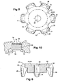
- the claws 26 generally have a trapezoidal shape when they are observed in a radial direction R, as can be seen in FIG. figure 6 for example.
- the claws 26 of one pole wheel form with the claws 26 of the other pole wheel interpolar spaces 28 arranged to receive one or more permanent magnets 30, as explained later in connection with the figure 10 .
- An excitation winding 34 is placed between the flanges 24 of the pole wheels 20 and 22.
- Each pole wheel 20; 22 has a bore forming an inner passage 38 for receiving the shaft 14.
- the pole wheels 20 and 22 are made for example of steel.
- the inductor rotor 12 creates an alternating induced current in the stator 16.
- the shaft 14 carries at its front end a pulley 40 belonging to a device for transmitting motion through at least one belt (not shown) between the alternator 1 and the engine of the motor vehicle, and its rear end 42 of the slip rings connected by wire links (not shown) to the excitation winding 34 of the rotor 12.
- Brushes of a brush holder 44 shown very schematically are arranged to rub on the slip rings, to supply the coil 34 with electrical current.
- the casing 10 comprises, in the example in question, two parts, namely a front bearing 46 substantially adjacent to the pulley 40 and a rear bearing 48 carrying the brush holder 44.
- the bearings 46 and 48 each carry a ball bearing 50 and 52 respectively for the rotational mounting of the shaft 14.
- the alternator 1 also comprises means for cooling it.
- the bearings 46 and 48 are perforated to allow the cooling of the alternator by air circulation.
- the rotor 12 carries, in the example described, at least at one of its axial ends a fan for ensuring air circulation.
- a first ventilation element 54 is for example provided on the front transverse face of the rotor 12 and a second ventilation element 56 is provided on the rear face of the rotor 12. Ventilator 54 and 56 is provided with a plurality of blades 58 and 60.
- each pole wheel 20; 22 has six claws 26 so as to define a rotor with 12 interpolar spaces 28.
- the rotor 12 may have 2, 4, 6, 8 or 10 interpolar spaces 28, depending on the type of electrical machine desired.
- Each claw 26 of a pole wheel 20; 22 has two side faces 70 defining with faces 70 of the other pole wheel 20; 22 interpolar spaces 28.
- Each side face 70 is provided with a groove 71 of substantially rectangular section, made in the example considered by machining as explained below.
- the magnets 30 inserted in the interpolar spaces 28 are permanent magnets, for example rare earth or ferrite, with in particular a rectangular cross section.
- a blade or laminate 72 may be disposed on the radially outer face of each magnet 30 with the interposition of an adhesive layer 73.
- the pole wheels 20 and 22 are made by molding a steel.
- Each pole wheel 20; 22 resulting from the molding comprises the flange 24 and the claws 26.
- each pole wheel 20; 22 at least one angular indexing mark 90, visible for example on the figure 4 , and whose role will be explained below.
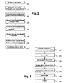
- This indexing mark 90 is formed, in the example described, during a calibration phase of the pole wheel, by machining the pole wheel 20; 22.
- the indexing mark 90 may be formed beforehand during the molding of the pole wheel 20; 22, then be caught by a cold stamp to remove any burr at the index mark 90.
- the indexing mark 90 has a notch formed on a sidewall 91 of the flange 24 of the pole wheel 20; 22.
- This mark 90 is present between two consecutive claws 26 of the pole wheel 20; 22, at equal angular distance from these two claws 26.
- the indexing mark 90 may have an arcuate cross section, as illustrated in FIG. figure 5 .
- the invention is not limited to this form of notch, which may have a polygon portion section for example.
- the indexing mark 90 may be present at a different location of the pole wheel 20; 22, being for example closer to one of the claws 26 than the other.
- each pole wheel 20; 22 has two angular indexing marks 90 diametrically opposed.
- each pole wheel 20; 22 may comprise a different number of indexing mark 90, for example a single indexing mark 90.
- the pole wheel 20; 22 is arranged on a machining machine, not shown, with an angular orientation determined according to the indexing marks 90 which serve as angular reference.
- the machine is equipped with holding rods that can cooperate with the indexing marks 90 to maintain the pole wheel 20; 22 in the predetermined angular position.
- a step 83 using a milling cutter of the machining machine to machining a circumferential face 94 of the claws 26 of the pole wheel 20; 22 (see figure 4 ) for finishing the outer diameter of the wheel.
- the machining machine is also controlled to form a bore in the pole wheel 20; 22 to form the inner passage 38.
- the pole piece 20; 22 is transported to another machining machine on which the pole wheel is placed in a desired angular position, in particular by making a holding rod of the machine cooperate with only one of the indexing marks, in connection with the introduction an expandable mandrel in the inner passage 38 of the pole wheel.
- the type of milling cutter used to machine the grooves 71 can be chosen so as to be able to form a groove 71, and thus an interpolar space 28, of reduced size, thus allowing to be able to insert in the interpolar spaces small magnets.
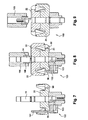
- steps 86 and 87 two pole wheels 20 and 22 are arranged on a base 103 of an assembly machine 100 shown on the drawings.
- Figures 7 to 9 are arranged on the drawings.
- the pole wheel 20 is introduced on the shaft 14 via the internal passage 38, while being held angularly by cooperation of the rod 90 with the indexing mark 90.
- the rod 101 is retracted and the other shorter rod 102 is engaged on the indexing mark 90 so as to release the space required to mount the other pole wheel 22, after installation of the coil 34 .
- the pole wheel 22 is held in a predetermined angular position by means of one or more holding rods (not shown) of the machine 100.
- a tool 105 with a blade 106 is brought against the wheel 22 so as to crimp the wheel 22 on the shaft 14.
Landscapes
- Engineering & Computer Science (AREA)
- Power Engineering (AREA)
- Manufacturing & Machinery (AREA)
- Manufacture Of Motors, Generators (AREA)
- Permanent Field Magnets Of Synchronous Machinery (AREA)
Claims (15)
- Verfahren zur Herstellung eines Rotors (12) einer rotierenden elektrischen Maschine (1), insbesondere einen Wechselstromgenerator, wobei der Rotor zwei Polräder (20; 22) aufweist, die zwischen sich mindestens eine Pollücke (28) definieren, die angeordnet ist, um mindestens einen Magneten (30) aufzunehmen, wobei das Verfahren vor dem Zusammenbau der beiden Polräder folgende Schritte umfasst:- Ausführen mindestens einer Winkelindexierungsmarke (90) auf mindestens einem der Polräder,- Ausbilden durch Bearbeitung mindestens einer Rille (71) auf dem Polrad, welche teilweise die Pollücke begrenzt, indem das Polrad in einer Winkelposition gehalten wird, die von der Winkelindexierungsmarke (90) abhängig ist.
- Verfahren nach dem vorhergehenden Anspruch, dadurch gekennzeichnet, dass es den Schritt umfasst, der darin besteht, vor dem Zusammenbau der beiden Polräder eine Umfangsfläche (94) mindestens eines der Polräder herzustellen, indem das Polrad in einer Winkelposition gehalten wird, die von der Winkelindexierungsmarke (90) abhängig ist.
- Verfahren nach einem der vorhergehenden Ansprüche, dadurch gekennzeichnet, dass es folgenden Schritt umfasst:- Herstellen einer Bohrung auf dem Polrad, um einen inneren Durchgang (38) auszubilden, um eine Welle (14) der rotierenden Maschine aufzunehmen, indem das Polrad in einer Winkelposition gehalten wird, die von der Indexierungsmarke (90) abhängig ist.
- Verfahren nach einem der vorhergehenden Ansprüche, dadurch gekennzeichnet, dass es folgenden Schritt umfasst:- Zusammenbauen der Polräder (20; 22), indem sie winklig zueinander mit Hilfe von Indexierungsmarken, die auf den Polrädern (90) ausgeführt sind, angeordnet werden.
- Verfahren nach einem der vorhergehenden Ansprüche, dadurch gekennzeichnet, dass die Haltung des Polrads in der vorgegebenen Winkelposition mit Hilfe mindestens einer Haltestange (101; 102) erfolgt, welche mit mindestens einer der Indexierungsmarken (90) des Polrads zusammenwirkt.
- Verfahren nach einem der vorhergehenden Ansprüche, wobei das Polrad mindestens zwei aufeinanderfolgende Greifer aufweist, dadurch gekennzeichnet, dass die Indexierungsmarke (90) zwischen zwei aufeinanderfolgenden Greifern (26) des Polrads ausgebildet ist.
- Verfahren nach einem der vorhergehenden Ansprüche, dadurch gekennzeichnet, dass die Indexierungsmarke (90) auf einer Seitenfläche (91) des Polrads ausgebildet ist, wobei die Indexierungsmarke insbesondere die Form einer Aussparung aufweist.
- Verfahren nach einem der vorhergehenden Ansprüche, dadurch gekennzeichnet, dass das Polrad zwei Winkelindexierungsmarken (90) aufweist, die insbesondere diametral gegenüberliegend angeordnet sind.
- Verfahren nach einem der vorhergehenden Ansprüche, dadurch gekennzeichnet, dass die Indexierungsmarke durch Entfernung von Material, insbesondere durch Bearbeitung, gebildet ist.
- Polrad (20; 22) für den Rotor einer rotierenden elektrischen Maschine, dadurch gekennzeichnet, dass es eine Winkelindexierungsmarke (90) aufweist, die insbesondere durch Entfernung von Material ausgeführt ist.
- Rad nach dem vorhergehenden Anspruch, dadurch gekennzeichnet, dass die Winkelindexierungsmarke (90) eine Aussparung aufweist, die zwischen zwei aufeinanderfolgenden Greifern des Polrads ausgebildet ist.
- Rad nach dem vorhergehenden Anspruch, dadurch gekennzeichnet, dass die Aussparung durch Bearbeitung des Polrads ausgeführt ist.
- Rad nach einem der Ansprüche 10 bis 12, dadurch gekennzeichnet, dass es mindestens einen Greifer (26) aufweist, auf dem mindestens eine Rille (71) ausgebildet ist, die dazu dient, nach dem Zusammenbau mit einem anderen Polrad eine Pollücke zu bilden, in der mindestens ein Magnet eingefügt ist.
- Rotor (12) für eine rotierende elektrische Maschine, aufweisend zwei Polräder, wie in einem der Ansprüche 10 bis 13 festgelegt.
- Rotierende elektrische Maschine (1), insbesondere ein Wechselstromgenerator für Kraftfahrzeuge, umfassend einen Stator und einen Rotor, wie in Anspruch 14 festgelegt.
Applications Claiming Priority (2)
| Application Number | Priority Date | Filing Date | Title |
|---|---|---|---|
| FR0755014A FR2916104B1 (fr) | 2007-05-11 | 2007-05-11 | Procede de fabrication d'un rotor de machine electrique tournante, notamment un alternateur |
| PCT/FR2008/050739 WO2008145929A2 (fr) | 2007-05-11 | 2008-04-23 | Procede de fabrication d'un rotor de machine electrique tournante, notamment un alternateur |
Publications (2)
| Publication Number | Publication Date |
|---|---|
| EP2145376A2 EP2145376A2 (de) | 2010-01-20 |
| EP2145376B1 true EP2145376B1 (de) | 2015-08-12 |
Family
ID=38828601
Family Applications (1)
| Application Number | Title | Priority Date | Filing Date |
|---|---|---|---|
| EP08805693.2A Active EP2145376B1 (de) | 2007-05-11 | 2008-04-23 | Verfahren zur herstellung eines rotors für eine rotierende elektrische maschine, insbesondere einen generator |
Country Status (4)
| Country | Link |
|---|---|
| US (1) | US9502950B2 (de) |
| EP (1) | EP2145376B1 (de) |
| FR (1) | FR2916104B1 (de) |
| WO (1) | WO2008145929A2 (de) |
Families Citing this family (5)
| Publication number | Priority date | Publication date | Assignee | Title |
|---|---|---|---|---|
| FR2901428B1 (fr) * | 2006-05-16 | 2008-09-19 | Valeo Equip Electr Moteur | Procede de realisation d'un rotor comportant une etape d'usinage de gorges dans les dents des poles et rotor obtenu par le procede |
| WO2014087461A1 (ja) * | 2012-12-03 | 2014-06-12 | 三菱電機株式会社 | 回転電機の回転子およびその製造方法 |
| FR3053542A1 (fr) * | 2016-06-29 | 2018-01-05 | Valeo Equipements Electriques Moteur | Rotor a double excitation pour machine electrique tournante |
| FR3080717B1 (fr) * | 2018-04-27 | 2021-01-22 | Valeo Equip Electr Moteur | Rotor de machine electrique tounante munie d'une repartition optimisee d'aimants interpolaires |
| FR3084537B1 (fr) * | 2018-07-27 | 2020-07-17 | Valeo Equipements Electriques Moteur | Rotor a griffes comportant des elements magnetiques inter-griffe pour machine electrique tournante |
Family Cites Families (12)
| Publication number | Priority date | Publication date | Assignee | Title |
|---|---|---|---|---|
| US4959577A (en) * | 1989-10-23 | 1990-09-25 | General Motors Corporation | Alternating current generator |
| JP3144567B2 (ja) * | 1991-08-28 | 2001-03-12 | 株式会社デンソー | 車両用交流発電機およびその製造方法 |
| FR2697694B1 (fr) * | 1992-11-04 | 1994-12-02 | Valeo Equip Electr Moteur | Alternateur pour véhicule automobile. |
| US5325003A (en) * | 1992-11-23 | 1994-06-28 | Ford Motor Company | Molded rotor assembly for an alternator and method for making the same |
| JP3446313B2 (ja) * | 1993-08-30 | 2003-09-16 | 株式会社デンソー | 回転電機の回転子 |
| US5543676A (en) * | 1995-03-16 | 1996-08-06 | Ford Motor Company | Rotating electrical machine with magnetic inserts |
| US5747913A (en) * | 1995-05-12 | 1998-05-05 | General Motors Corporation | Rotor for hybrid generator having improved magnet retention |
| JP3922754B2 (ja) * | 1997-03-05 | 2007-05-30 | 株式会社デンソー | 車両用交流発電機 |
| FR2793085B1 (fr) * | 1999-04-30 | 2001-07-13 | Valeo Equip Electr Moteur | Alternateur pour vehicule automobile a aimants interpolaires |
| DE19951115A1 (de) * | 1999-10-23 | 2001-05-03 | Bosch Gmbh Robert | Elektrische Maschine |
| FR2850805B1 (fr) * | 2002-12-16 | 2009-01-09 | Valeo Equip Electr Moteur | Dispositif de ventilation pour machine electrique tournante |
| FR2858367B1 (fr) * | 2003-05-30 | 2006-01-27 | Valeo Equip Electr Moteur | Dispositif de positionnement angulaire d'une culasse de demarreur par rapport a son support |
-
2007
- 2007-05-11 FR FR0755014A patent/FR2916104B1/fr not_active Expired - Fee Related
-
2008
- 2008-04-23 WO PCT/FR2008/050739 patent/WO2008145929A2/fr not_active Ceased
- 2008-04-23 EP EP08805693.2A patent/EP2145376B1/de active Active
- 2008-04-23 US US12/599,559 patent/US9502950B2/en active Active
Also Published As
| Publication number | Publication date |
|---|---|
| WO2008145929A2 (fr) | 2008-12-04 |
| WO2008145929A3 (fr) | 2010-01-28 |
| FR2916104A1 (fr) | 2008-11-14 |
| US20100257723A1 (en) | 2010-10-14 |
| FR2916104B1 (fr) | 2009-07-31 |
| US9502950B2 (en) | 2016-11-22 |
| EP2145376A2 (de) | 2010-01-20 |
Similar Documents
| Publication | Publication Date | Title |
|---|---|---|
| EP1864365B1 (de) | Elektrische drehmaschine mit einem zwischen dem schaft und den polarrädern angeordneten zwischenmantel und verfahren zur herstellung des rotors | |
| EP2499720B1 (de) | Klauenrotor mit feldspulenisolierung und magneten sowie elektrische drehmaschine mit einem derartigen klauenrotor | |
| FR2819350A1 (fr) | Machine tournante perfectionnee pour vehicules automobiles | |
| EP2856612A1 (de) | Rotor einer elektrischen maschine und zugehörige vorrichtung zum halten eines dauermagneten | |
| EP2018698A2 (de) | Verfahren zum herstellen eines rotors mit einem schritt des maschinenbearbeitens von rillen in den zähnen der pole und durch das verfahren erhaltener rotor | |
| WO2022069096A1 (fr) | Rotor de machine electrique et procede d'assemblage d'un tel rotor | |
| EP2912754B1 (de) | Metallblechstapel zur montage über ein zylindrisches teil | |
| WO2008145929A2 (fr) | Procede de fabrication d'un rotor de machine electrique tournante, notamment un alternateur | |
| EP2157679A1 (de) | Rotor einer synchron umlaufenden Elektromaschine, insbesondere Lichtmaschine für Kraftfahrzeug | |
| FR3054746B1 (fr) | Machine electrique tournante munie d'un interconnecteur dote de bequilles d'appui | |
| EP3322612B1 (de) | Drehende elektrische maschine für ein fahrzeug | |
| EP2283561B1 (de) | Rotor für elektrische drehmaschine mit interpolaren strukturen mit verringerter masse | |
| FR3069972A1 (fr) | Rotor a aimants concentriques pour machine electrique tournante | |
| EP2194631B1 (de) | Stator einer rotierenden elektrischen Maschine, insbesondere einer Lichtmaschine | |
| FR3117703A1 (fr) | dispositif de roulement pour machine électrique tournante | |
| WO2021099023A1 (fr) | Rotor pour machine électrique tournante | |
| EP3008796B1 (de) | Rotor einer elektrischen drehenden maschine mit einem isolator einer erregerwicklung mit mindestens einer modifizierten lamelle für den durchgang eines magnets während des zusammenbaus | |
| EP3107193B1 (de) | Rotor mit stapelblechen | |
| EP2218158B1 (de) | Rotoranordnung für eine elektrische maschine klauenpole und magnetstrukturen in den polenluecken aufweisend | |
| WO2018020188A1 (fr) | Machine electrique tournante munie d'un stator avec un bobinage epingle | |
| EP2452406B1 (de) | Kommutator einer drehenden elektrischen maschine für ein fahrzeug | |
| WO2019016242A1 (fr) | Machine electrique tournante comportant un dispositif de maintien de l'extremite d'un fil electrique participant au bobinage | |
| WO2017013325A1 (fr) | Stator de demarreur pour vehicule automobile a performances magnetiques ameliorees | |
| FR3120999A1 (fr) | Rotor de machine électrique tournante | |
| FR3084786A1 (fr) | Machine electrique a aimants permanents pour turbomachine |
Legal Events
| Date | Code | Title | Description |
|---|---|---|---|
| PUAI | Public reference made under article 153(3) epc to a published international application that has entered the european phase |
Free format text: ORIGINAL CODE: 0009012 |
|
| 17P | Request for examination filed |
Effective date: 20090914 |
|
| AK | Designated contracting states |
Kind code of ref document: A2 Designated state(s): AT BE BG CH CY CZ DE DK EE ES FI FR GB GR HR HU IE IS IT LI LT LU LV MC MT NL NO PL PT RO SE SI SK TR |
|
| AX | Request for extension of the european patent |
Extension state: AL BA MK RS |
|
| R17D | Deferred search report published (corrected) |
Effective date: 20100128 |
|
| RIC1 | Information provided on ipc code assigned before grant |
Ipc: H02K 15/03 20060101AFI20100203BHEP |
|
| DAX | Request for extension of the european patent (deleted) | ||
| 17Q | First examination report despatched |
Effective date: 20130328 |
|
| GRAP | Despatch of communication of intention to grant a patent |
Free format text: ORIGINAL CODE: EPIDOSNIGR1 |
|
| INTG | Intention to grant announced |
Effective date: 20150312 |
|
| RIN1 | Information on inventor provided before grant (corrected) |
Inventor name: GAS, OLIVIER Inventor name: PFLEGER, ALEXANDRE |
|
| GRAS | Grant fee paid |
Free format text: ORIGINAL CODE: EPIDOSNIGR3 |
|
| GRAA | (expected) grant |
Free format text: ORIGINAL CODE: 0009210 |
|
| AK | Designated contracting states |
Kind code of ref document: B1 Designated state(s): AT BE BG CH CY CZ DE DK EE ES FI FR GB GR HR HU IE IS IT LI LT LU LV MC MT NL NO PL PT RO SE SI SK TR |
|
| REG | Reference to a national code |
Ref country code: GB Ref legal event code: FG4D Free format text: NOT ENGLISH |
|
| REG | Reference to a national code |
Ref country code: CH Ref legal event code: EP |
|
| REG | Reference to a national code |
Ref country code: AT Ref legal event code: REF Ref document number: 742908 Country of ref document: AT Kind code of ref document: T Effective date: 20150815 |
|
| REG | Reference to a national code |
Ref country code: IE Ref legal event code: FG4D Free format text: LANGUAGE OF EP DOCUMENT: FRENCH |
|
| REG | Reference to a national code |
Ref country code: DE Ref legal event code: R096 Ref document number: 602008039549 Country of ref document: DE |
|
| REG | Reference to a national code |
Ref country code: LT Ref legal event code: MG4D |
|
| REG | Reference to a national code |
Ref country code: AT Ref legal event code: MK05 Ref document number: 742908 Country of ref document: AT Kind code of ref document: T Effective date: 20150812 |
|
| REG | Reference to a national code |
Ref country code: NL Ref legal event code: MP Effective date: 20150812 |
|
| PG25 | Lapsed in a contracting state [announced via postgrant information from national office to epo] |
Ref country code: NO Free format text: LAPSE BECAUSE OF FAILURE TO SUBMIT A TRANSLATION OF THE DESCRIPTION OR TO PAY THE FEE WITHIN THE PRESCRIBED TIME-LIMIT Effective date: 20151112 Ref country code: LT Free format text: LAPSE BECAUSE OF FAILURE TO SUBMIT A TRANSLATION OF THE DESCRIPTION OR TO PAY THE FEE WITHIN THE PRESCRIBED TIME-LIMIT Effective date: 20150812 Ref country code: LV Free format text: LAPSE BECAUSE OF FAILURE TO SUBMIT A TRANSLATION OF THE DESCRIPTION OR TO PAY THE FEE WITHIN THE PRESCRIBED TIME-LIMIT Effective date: 20150812 Ref country code: FI Free format text: LAPSE BECAUSE OF FAILURE TO SUBMIT A TRANSLATION OF THE DESCRIPTION OR TO PAY THE FEE WITHIN THE PRESCRIBED TIME-LIMIT Effective date: 20150812 Ref country code: GR Free format text: LAPSE BECAUSE OF FAILURE TO SUBMIT A TRANSLATION OF THE DESCRIPTION OR TO PAY THE FEE WITHIN THE PRESCRIBED TIME-LIMIT Effective date: 20151113 |
|
| PG25 | Lapsed in a contracting state [announced via postgrant information from national office to epo] |
Ref country code: SE Free format text: LAPSE BECAUSE OF FAILURE TO SUBMIT A TRANSLATION OF THE DESCRIPTION OR TO PAY THE FEE WITHIN THE PRESCRIBED TIME-LIMIT Effective date: 20150812 Ref country code: IS Free format text: LAPSE BECAUSE OF FAILURE TO SUBMIT A TRANSLATION OF THE DESCRIPTION OR TO PAY THE FEE WITHIN THE PRESCRIBED TIME-LIMIT Effective date: 20151212 Ref country code: AT Free format text: LAPSE BECAUSE OF FAILURE TO SUBMIT A TRANSLATION OF THE DESCRIPTION OR TO PAY THE FEE WITHIN THE PRESCRIBED TIME-LIMIT Effective date: 20150812 Ref country code: PL Free format text: LAPSE BECAUSE OF FAILURE TO SUBMIT A TRANSLATION OF THE DESCRIPTION OR TO PAY THE FEE WITHIN THE PRESCRIBED TIME-LIMIT Effective date: 20150812 Ref country code: HR Free format text: LAPSE BECAUSE OF FAILURE TO SUBMIT A TRANSLATION OF THE DESCRIPTION OR TO PAY THE FEE WITHIN THE PRESCRIBED TIME-LIMIT Effective date: 20150812 Ref country code: ES Free format text: LAPSE BECAUSE OF FAILURE TO SUBMIT A TRANSLATION OF THE DESCRIPTION OR TO PAY THE FEE WITHIN THE PRESCRIBED TIME-LIMIT Effective date: 20150812 Ref country code: PT Free format text: LAPSE BECAUSE OF FAILURE TO SUBMIT A TRANSLATION OF THE DESCRIPTION OR TO PAY THE FEE WITHIN THE PRESCRIBED TIME-LIMIT Effective date: 20151214 |
|
| PG25 | Lapsed in a contracting state [announced via postgrant information from national office to epo] |
Ref country code: NL Free format text: LAPSE BECAUSE OF FAILURE TO SUBMIT A TRANSLATION OF THE DESCRIPTION OR TO PAY THE FEE WITHIN THE PRESCRIBED TIME-LIMIT Effective date: 20150812 |
|
| PG25 | Lapsed in a contracting state [announced via postgrant information from national office to epo] |
Ref country code: DK Free format text: LAPSE BECAUSE OF FAILURE TO SUBMIT A TRANSLATION OF THE DESCRIPTION OR TO PAY THE FEE WITHIN THE PRESCRIBED TIME-LIMIT Effective date: 20150812 Ref country code: EE Free format text: LAPSE BECAUSE OF FAILURE TO SUBMIT A TRANSLATION OF THE DESCRIPTION OR TO PAY THE FEE WITHIN THE PRESCRIBED TIME-LIMIT Effective date: 20150812 Ref country code: IT Free format text: LAPSE BECAUSE OF FAILURE TO SUBMIT A TRANSLATION OF THE DESCRIPTION OR TO PAY THE FEE WITHIN THE PRESCRIBED TIME-LIMIT Effective date: 20150812 Ref country code: SK Free format text: LAPSE BECAUSE OF FAILURE TO SUBMIT A TRANSLATION OF THE DESCRIPTION OR TO PAY THE FEE WITHIN THE PRESCRIBED TIME-LIMIT Effective date: 20150812 |
|
| REG | Reference to a national code |
Ref country code: DE Ref legal event code: R097 Ref document number: 602008039549 Country of ref document: DE |
|
| PG25 | Lapsed in a contracting state [announced via postgrant information from national office to epo] |
Ref country code: RO Free format text: LAPSE BECAUSE OF FAILURE TO SUBMIT A TRANSLATION OF THE DESCRIPTION OR TO PAY THE FEE WITHIN THE PRESCRIBED TIME-LIMIT Effective date: 20150812 |
|
| PLBE | No opposition filed within time limit |
Free format text: ORIGINAL CODE: 0009261 |
|
| STAA | Information on the status of an ep patent application or granted ep patent |
Free format text: STATUS: NO OPPOSITION FILED WITHIN TIME LIMIT |
|
| 26N | No opposition filed |
Effective date: 20160513 |
|
| PG25 | Lapsed in a contracting state [announced via postgrant information from national office to epo] |
Ref country code: BE Free format text: LAPSE BECAUSE OF NON-PAYMENT OF DUE FEES Effective date: 20160430 Ref country code: SI Free format text: LAPSE BECAUSE OF FAILURE TO SUBMIT A TRANSLATION OF THE DESCRIPTION OR TO PAY THE FEE WITHIN THE PRESCRIBED TIME-LIMIT Effective date: 20150812 |
|
| REG | Reference to a national code |
Ref country code: CH Ref legal event code: PL |
|
| GBPC | Gb: european patent ceased through non-payment of renewal fee |
Effective date: 20160423 |
|
| PG25 | Lapsed in a contracting state [announced via postgrant information from national office to epo] |
Ref country code: LU Free format text: LAPSE BECAUSE OF FAILURE TO SUBMIT A TRANSLATION OF THE DESCRIPTION OR TO PAY THE FEE WITHIN THE PRESCRIBED TIME-LIMIT Effective date: 20160423 |
|
| REG | Reference to a national code |
Ref country code: IE Ref legal event code: MM4A |
|
| REG | Reference to a national code |
Ref country code: FR Ref legal event code: ST Effective date: 20161230 |
|
| PG25 | Lapsed in a contracting state [announced via postgrant information from national office to epo] |
Ref country code: CH Free format text: LAPSE BECAUSE OF NON-PAYMENT OF DUE FEES Effective date: 20160430 Ref country code: FR Free format text: LAPSE BECAUSE OF NON-PAYMENT OF DUE FEES Effective date: 20160502 Ref country code: LI Free format text: LAPSE BECAUSE OF NON-PAYMENT OF DUE FEES Effective date: 20160430 Ref country code: GB Free format text: LAPSE BECAUSE OF NON-PAYMENT OF DUE FEES Effective date: 20160423 |
|
| PG25 | Lapsed in a contracting state [announced via postgrant information from national office to epo] |
Ref country code: IE Free format text: LAPSE BECAUSE OF NON-PAYMENT OF DUE FEES Effective date: 20160423 |
|
| PG25 | Lapsed in a contracting state [announced via postgrant information from national office to epo] |
Ref country code: CY Free format text: LAPSE BECAUSE OF FAILURE TO SUBMIT A TRANSLATION OF THE DESCRIPTION OR TO PAY THE FEE WITHIN THE PRESCRIBED TIME-LIMIT Effective date: 20150812 Ref country code: HU Free format text: LAPSE BECAUSE OF FAILURE TO SUBMIT A TRANSLATION OF THE DESCRIPTION OR TO PAY THE FEE WITHIN THE PRESCRIBED TIME-LIMIT; INVALID AB INITIO Effective date: 20080423 |
|
| PG25 | Lapsed in a contracting state [announced via postgrant information from national office to epo] |
Ref country code: MC Free format text: LAPSE BECAUSE OF FAILURE TO SUBMIT A TRANSLATION OF THE DESCRIPTION OR TO PAY THE FEE WITHIN THE PRESCRIBED TIME-LIMIT Effective date: 20150812 Ref country code: MT Free format text: LAPSE BECAUSE OF FAILURE TO SUBMIT A TRANSLATION OF THE DESCRIPTION OR TO PAY THE FEE WITHIN THE PRESCRIBED TIME-LIMIT Effective date: 20150812 Ref country code: TR Free format text: LAPSE BECAUSE OF FAILURE TO SUBMIT A TRANSLATION OF THE DESCRIPTION OR TO PAY THE FEE WITHIN THE PRESCRIBED TIME-LIMIT Effective date: 20150812 |
|
| PG25 | Lapsed in a contracting state [announced via postgrant information from national office to epo] |
Ref country code: BG Free format text: LAPSE BECAUSE OF FAILURE TO SUBMIT A TRANSLATION OF THE DESCRIPTION OR TO PAY THE FEE WITHIN THE PRESCRIBED TIME-LIMIT Effective date: 20150812 |
|
| PGFP | Annual fee paid to national office [announced via postgrant information from national office to epo] |
Ref country code: CZ Payment date: 20190318 Year of fee payment: 12 |
|
| PG25 | Lapsed in a contracting state [announced via postgrant information from national office to epo] |
Ref country code: CZ Free format text: LAPSE BECAUSE OF NON-PAYMENT OF DUE FEES Effective date: 20200423 |
|
| P01 | Opt-out of the competence of the unified patent court (upc) registered |
Effective date: 20230528 |
|
| PGFP | Annual fee paid to national office [announced via postgrant information from national office to epo] |
Ref country code: DE Payment date: 20250411 Year of fee payment: 18 |