EP2145565A2 - Dispositif de positionnement en hauteur pour un dispositif de présentation - Google Patents
Dispositif de positionnement en hauteur pour un dispositif de présentation Download PDFInfo
- Publication number
- EP2145565A2 EP2145565A2 EP08017222A EP08017222A EP2145565A2 EP 2145565 A2 EP2145565 A2 EP 2145565A2 EP 08017222 A EP08017222 A EP 08017222A EP 08017222 A EP08017222 A EP 08017222A EP 2145565 A2 EP2145565 A2 EP 2145565A2
- Authority
- EP
- European Patent Office
- Prior art keywords
- height
- carrier
- positioning device
- presentation
- holder
- Prior art date
- Legal status (The legal status is an assumption and is not a legal conclusion. Google has not performed a legal analysis and makes no representation as to the accuracy of the status listed.)
- Withdrawn
Links
Images


Classifications
-
- A—HUMAN NECESSITIES
- A47—FURNITURE; DOMESTIC ARTICLES OR APPLIANCES; COFFEE MILLS; SPICE MILLS; SUCTION CLEANERS IN GENERAL
- A47B—TABLES; DESKS; OFFICE FURNITURE; CABINETS; DRAWERS; GENERAL DETAILS OF FURNITURE
- A47B97/00—Furniture or accessories for furniture, not provided for in other groups of this subclass
- A47B97/04—Easels or stands for blackboards or the like
- A47B97/06—Easels or stands for blackboards or the like with means for balancing weight of blackboards or the like, e.g. connected to wall
-
- G—PHYSICS
- G03—PHOTOGRAPHY; CINEMATOGRAPHY; ANALOGOUS TECHNIQUES USING WAVES OTHER THAN OPTICAL WAVES; ELECTROGRAPHY; HOLOGRAPHY
- G03B—APPARATUS OR ARRANGEMENTS FOR TAKING PHOTOGRAPHS OR FOR PROJECTING OR VIEWING THEM; APPARATUS OR ARRANGEMENTS EMPLOYING ANALOGOUS TECHNIQUES USING WAVES OTHER THAN OPTICAL WAVES; ACCESSORIES THEREFOR
- G03B21/00—Projectors or projection-type viewers; Accessories therefor
- G03B21/54—Accessories
Definitions
- the present invention relates to a height positioning device for a presentation device.
- presentation systems mounted on a building wall
- mobile i. for example, presentation systems provided with a movable undercarriage.
- presentation systems are adjustable in height in order to be able to optimally adapt the systems to the current circumstances.
- the corresponding fatiguenpositioniervorraumen should be as easy to use.
- a lower weight of the height positioning device is advantageous both in the case of a mobile presentation system and in the case of a fixed mounting of a presentation system. Further advantages arise with regard to transport and logistics of the height positioning devices or the entire presentation systems.
- the DE 102 48 987 A1 a mobile presentation unit, which has an integrated electronic presentation device and can be variably used for presentations in a limited circle of participants.
- This known presentation unit has, in particular, a movable underframe with a plurality of support profiles and a support structure for fastening the presentation device, For example, a whiteboard or a built-in unit of projection board and projector on.
- the DE 20 2007 010 920 U1 discloses a presentation system having a projection surface and a projector attached thereto via a pivotable arm about a vertical axis, in which the projection surface is fastened to a plurality of pylons via a height-adjustable support and coupled with counterweights.
- This conventional presentation system can optionally be arranged on a wall, on wall rails or on a mobile frame.
- the support structure comprises at least one substantially vertical pylons with a counterweight, on which a carrier is slidably disposed between a first and a second height position, and the projection surface and the support arm of the projector are respectively attached to the carrier ,
- the support arm is preferably designed so that the projector can be folded down from its operating position above the projection surface down in front of the projection surface.
- Another height adjustable pylon board is for example from the DE 20 2006 007 109 U1
- the panel surface can additionally be inclined with respect to the substantially vertical pylons.
- the height positioning device Since the counterweights provided in or on the pylons must substantially correspond to the total weight of the carrier and the presentation elements attached thereto and their holders, the height positioning device has a relatively large weight in the latter cases, which is the case for mobile presentation systems and stationary mounting on wall rails and the like is disadvantageous.
- DE-OS 19 18 262 a continuously height-adjustable panel, which can be held by means of a centrally disposed gas spring and a symmetrically constructed pulley arrangement in a desired height position on a building wall.
- This height positioning is an integral part of a school blackboard or the like and thus not flexible for the different modern presentation elements used.
- the height positioning device for a presentation device of the invention comprises a carrier to which at least one presentation element is attachable, and a holder to which the carrier is slidably mounted between a first and a second height position.
- a flexible one Traction means one end of which is fixed to the carrier or a movable element with the carrier and the other end is fixed to the holder or a height-resistant element, and at least one deflecting element, around which guided the at least one traction means in the manner of a pulley is provided.
- a pneumatic piston mechanism is further provided at one end of which at least one deflecting element is fixed and the other end to the holder or a height-resistant element or is supported on the carrier or a movable element with the carrier, that the piston mechanism substantially compensates for a total weight of the carrier and the at least one presentation element attachable thereto.
- An essential part of the height positioning device according to the invention is the height-displaceable support on which the or the respective (s) presentation element (s) can be attached.
- this carrier By this carrier, a separation of height positioning and presentation element (s) is achieved, so that a height positioning device can be used in a variable manner for different presentation devices, which increases the flexibility of the height positioning and reduces the manufacturing cost.
- the pneumatic piston mechanism for weight balance of the carrier and presentation element (s) has a relatively low weight compared to a counterweight in conventional devices, which brings advantages in the mobility or assembly of the entire presentation device as well as in logistics and transport. Since the at least one traction means is coupled via the at least one deflecting element to the piston mechanism in the manner of a pulley, the piston mechanism must provide a greater force, but a significantly smaller stroke compared to, for example, the principle of the jack, which simplifies the assembly of the piston mechanism ,
- exactly one piston mechanism is provided, which is preferably arranged substantially centrally in the width direction of the carrier and preferably runs essentially vertically.
- a traction means is provided, which is guided between two attachment points on the at least one deflection roller of the pulley, wherein the two attachment points are arranged substantially centrally in the width direction of the carrier.
- two traction means and two parallel pulleys of the pulley are provided, wherein the two traction means are each guided between two attachment points on one of the two parallel pulleys of the pulley, wherein the one attachment points of the two traction means are provided on different sides of the support.
- the two sides of the support for the presentation elements are urged synchronously by the piston mechanism, i. synchronously moved and held.
- the one attachment point is arranged laterally of the carrier in the width direction of the carrier, and the other attachment point is arranged substantially centrally in the width direction of the carrier
- the pneumatic piston mechanism is a gas spring, preferably a damped gas spring.
- the at least one traction means is guided in the manner of a simple pulley.
- a simple pulley achieves an optimal compromise in terms of the working stroke, power and cost of the pneumatic piston mechanism. Without pulley, ie at a ratio of 1: 1, would be a very large stroke of the piston mechanism required, with a double pulley a very large force of the piston mechanism would be required.
- the holder has a first guide element and the carrier has a complementary to this first guide element second guide element, so that the carrier is guided between the first and the second height position along the holder.
- the holder of the height positioning device according to the invention can optionally be mounted on a mobile base or attached to a stationary element.
- At least one further panel element can also be attached to the support and / or the holder of the height positioning device. This is preferably designed or mounted pivotable / hinged.
- the height positioning device in a fixed mounting of the height positioning device according to the invention, for example, on a wall rail or the like, it is advantageous if at least one support arm or the like for attachment or storage of at least one peripheral device (eg computer) of the presentation elements on the holder and / or the carrier of the height positioning the presentation device is provided.
- at least one support arm or the like for attachment or storage of at least one peripheral device (eg computer) of the presentation elements on the holder and / or the carrier of the height positioning the presentation device is provided.
- the at least one presentation element that can be attached to the support of the height-positioning device can be selected, for example, from a screen, a (preferably interactive) whiteboard, a (preferably interactive) projection board, an integrated projection-board unit, and a projector projecting thereon, a projection board and a projector mounted on a projector arm and facing the projection panel, a projector, and the like.
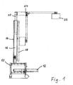
- Fig. 1 First, the basic structure of a mobile presentation device is shown, in which the height positioning of the invention can be used.
- the presentation device has a movable base 10 with a plurality of castors, which is formed, for example in the form of a piece of furniture such as a shelf unit, sideboards or the like.
- the presentation device can be flexibly used in different places and it must, for example, not be purchased for each classroom or meeting room own presentation device.
- the base frame 10 preferably has a plurality of receptacles 12, which are formed for example in the form of a compartment or a drawer and preferably closable, more preferably are lockable.
- the receptacles 12 of the undercarriage 10 are used in particular for receiving peripheral devices of the presentation elements of this presentation device.
- the peripheral devices include, for example, a controller, a computer, a printer, and the like.
- peripherals also include pens, pointing devices and the like for activating a projection screen by the user (s).
- the electrical connections for the presentation elements and the complete cable management are housed.
- the electrical connections include in particular connections for the power supply and the communication of the presentation elements with each other and with other devices and network (works). Also, preferably, different and each more such connections are provided.
- This height positioning device comprises in particular a holder or supporting structure 14 and a carrier 16.
- the holder 14 has in the exemplary embodiments illustrated here two parallel pylons or columns on which the carrier 16 between a first and a second height position is slidably mounted.
- the carrier 16 is formed substantially plate-shaped or frame-shaped.
- the present invention is not limited only to this holder 14.
- the holder 14 may, for example, also have only one pylon or more than two pylons. Instead of pylons, other columns, columns, support members and the like may be used.
- One or more presentation elements may be attached to the support 16 of the height positioning device.
- a projection board 18, preferably an interactive projection board, and a projector mount 20 with a projector 22 mounted thereon are attached.
- the operating position of the projector 22 (solid lines in Fig. 1 ) is located at a predetermined position above the projection board 18th
- the projector mount 20 is preferably formed so that the projector in a non-use position (dash-dotted lines in Fig. 1 ) can be folded down in front of the projection board 18 down.
- the projector mount 20 has, for example, a special hinge 24 or the like.
- a special hinge 24 or the like.
- the presentation device with the folded down and protected in this non-operating position projector 22 can be driven through doors with standard dimensions and occupies less space when not in use.
- the presentation elements are an interactive projection board and a projector directed thereon.
- presentation elements or other combinations of presentation elements can be attached to the support 16 of the height positioning in the invention.
- presentation elements are for example, a screen, a whiteboard, a projection board, an integrated projection-board unit and projector projecting thereon, a projector, and the like.
- the present invention is not limited to the attachment of the projector 22 via a downwardly tiltable projector arm 20.
- a rigid projector arm or a side i. be used about a substantially vertical axis pivoting projector arm.
- a telescopic technique for the projector arm can be used.
- the height positioning device of the present invention will be described here using the example of a mobile presentation device in which the height positioning device is mounted on a mobile base.
- the height positioning device of the invention may also be attached to a stationary member such as a building wall, a room partition, a cabinet member or the like.
- the height positioning can also be mounted on a wall rail, which is attached to one of said stationary elements or mounted, so that the height positioning and thus the entire presentation device can be moved laterally within the wall rail.
- a mobile presentation device with a movable base preferably a plurality of receptacles, shelves or the like are provided on this base
- this is not possible in an alternative presentation device of the invention, which is mounted on a wall rail, a stationary element or the like.
- an attachment device for example in the form of a pivotable and / or height-adjustable arm is attached to the holder 14 of the height positioning, over which the presentation device can be hung on a wall rail, for example, a tray or a Attachment example, for a notebook for driving the presentation elements 18, 22 of the presentation device has.
- the Electrical connections and communication connections are accommodated in the holder 14 accordingly.
- a first guide member 36 in the form of a substantially vertically extending guide rail and the carrier 16 is provided with a plurality of rollers 34 as a second guide member.
- the first and second guide members 34, 36 are not limited to this combination of guide rail and rollers; For example, it is also possible to provide two guide rails running one inside the other. The two guide elements only have to match each other, ie be complementary to each other and / or arranged.
- the height positioning device further comprises a pneumatic piston mechanism in the form of a gas spring 26, preferably a damped gas spring.
- a pneumatic piston mechanism in the form of a gas spring 26, preferably a damped gas spring.
- the one gas spring 26 in the width direction of the height positioning (right-left direction in Fig. 2 to 4 ) arranged substantially centrally.
- the piston rod 27 of the gas spring 26 in the lowest height position of the carrier 16 (FIG. Fig. 2 ) and in its highest altitude position ( Fig. 3 ) extended.
- the lower end of the gas spring 26 is supported against a support bracket 30, which in the case of the mobile presentation device to the bracket 14 or the base 10 may be attached.
- this support bracket 30 is attached, for example, to the bracket 14 or a building wall.
- This support bracket 30 is generally attached to a height-resistant element, ie it does not move with the carrier in its movement in the vertical direction.
- the support bracket 30 also forms an attachment point for one end of a traction device.
- a deflection roller 28 is mounted at the other end (top in Fig. 2 and 3 ) of the gas spring 26 at the other end (top in Fig. 2 and 3 ) of the gas spring 26 at the other end (top in Fig. 2 and 3 ) of the gas spring 26 at the other end (top in Fig. 2 and 3 ) of the gas spring 26 at the other end (top in Fig. 2 and 3 ) of the gas spring 26 at the other end (top in Fig. 2 and 3 ) of the gas spring 26 is .
- the lower end of the carrier 16 is coupled to the piston rod 27 of the gas spring 26, so that the piston rod 27 is extended when pushing up the carrier 16 and retracted when the carrier 16 is pushed down.
- a second attachment point 32 is provided for the traction means.
- the flexible traction means (not shown in FIG Fig. 2 to 4 ), for example, a rope-like, belt-like or chain-like traction means, runs between the height-resistant first attachment point on the support bracket 30 of the gas spring 26 and with the carrier 16 with moving second attachment point 32 via the guide roller 28. In this way, a simple pulley is formed, wherein the stroke of the gas spring 26 and its piston rod 27 is transmitted in a transmission ratio of 1: 2 to the height displacement of the carrier 16.
- the gas spring 26 is designed, dimensioned or adjusted so that its spring force substantially equalizes the total weight of the carrier 16 and the presentation elements 18, 22 attached thereto and their mounting means 20, 24.
- the carrier 16 can thus be easily moved by the user between its two relienendpositionen infinitely and the desired height position is then securely retained by the gas spring 26.
- a diaphragm 15 is arranged so that the gas spring 26, the guide roller 28 and the traction means for the user are not visible and not accessible to provide an attractive appearance and the risk of injury for the user to minimize.
- Fig. 5 shows the carrier 16 of the height positioning device in its lowest height end position and Fig. 6 shows the wearer in his highest height end position.
- On the carrier 16 analogously to the above first embodiment, one or more presentation elements can be attached again.
- this height positioning is optionally mounted on or on a movable base or on a stationary element (building wall, cabinet, etc.).
- the second embodiment of the height positioning device differs from that in FIG Fig. 2 to 4 shown height positioning device by a synchronous support of the carrier 16 on its two sides. Due to this synchronous support of the two carrier sides, lower requirements are placed on the first and second guide elements 34, 36 of holder 14 and carrier 16, since the vertical movement of the carrier between its two height end positions is performed without canting the carrier 16.
- the height positioning device has, as in Fig. 5 and 6 illustrates, for this purpose, a pneumatic piston mechanism 26 in the form of a gas spring, preferably a damped gas spring, which is analogous to the first embodiment in the width direction of the carrier 16 (right-left direction in FIG Fig. 5 and 6 ) is arranged substantially centrally and extends substantially vertically.
- the gas spring 26 is positioned so that its piston rod 27 extends downwards and in the lowest height position of the carrier 16 (FIG. Fig. 5 ) and in the highest height position of the carrier 16 ( Fig. 6 ) is extended.
- the gas spring 26 is supported at its lower end, ie with its piston rod 27, on a support block 31 which on the support 16 (or optionally on a other moving with the carrier 16 element) is mounted.
- This support block 31 also serves as an attachment point for the two traction means 40, 42 to be described later.
- the sleeve of the gas spring 26 is guided on a rail-like guide 38, for example, which is fixedly arranged on the carrier 16.
- a rail-like guide 38 for example, which is fixedly arranged on the carrier 16.
- two guide rollers 28 are provided, which are preferably arranged parallel to each other on a common axis of rotation.
- two further (second) pulleys 44 are integrated, which are also preferably arranged parallel to each other on a common axis of rotation.
- Two third deflection rollers 46 are each provided on one side of the carrier 16, and two further attachment points 48 for the traction means 40, 42 are each on one side of the bracket 14 at a height above the third guide rollers 46 in the highest height position of the carrier 16 angel assigns.
- a first traction means 40 extends from the first attachment point on the support block 31 upwards to one of the two deflection rollers 28, where it is deflected by 180 ° and guided back down to one of the two second deflection rollers 44, so that a simple pulley is formed.
- the first traction means 40 is substantially at about 90 ° to one side (to the right in Fig. 5 and 6 ) of the carrier 16, where it wraps around the third deflection roller 46 substantially by about 90 °. From this third deflection roller 46, the first traction means 40 extends upwardly to the second attachment point 46 on one side (on the right in FIG Fig. 5 and 6 ) of the holder 14 of the height positioning device.
- a second flexible traction means 42 extends from the first attachment point on the support block 31 upwards to the other first guide roller 28 of the simple pulley block, from there down to the other second guide pulley 44, from there to the other side (to the left in FIG Fig. 5 and 6 ) of the carrier 16 to the other third guide roller 46, and from there to finally above the second attachment point 48 on the other side (left in Fig. 5 and 6 ) on the bracket 16.
- the path of the traction means 40, 42 is shortened from the height-fixed attachment point 48 on the holder 16 to the second guide roller 44 in the support block 31.
- the path of the traction means 40, 42 is shortened from the height-fixed attachment point 48 on the holder 16 to the second guide roller 44 in the support block 31.
- To compensate for the distance between the support block 31 and the first guide roller 28 of the pulley is extended by extending the piston rod 27 of the gas spring 26 by half of the first-mentioned path change.
- the operation when lowering the carrier 16 is analogue in the reverse manner.
- Each of the two traction means 40, 42 supports or holds one of the two sides of the carrier 16, so that a synchronous height positioning takes place, for which purpose only a central gas spring 26 is required. Even if the user attacks the carrier 16 or the attached projection board 18 for height adjustment on one side, the entire carrier 16 is moved with this structure without tilting evenly upwards. In principle, it would also be conceivable to arrange a gas spring 26 on each side of the carrier 16. However, the use of two gas struts 26 would increase the overall cost of the height positioning device.
- a gas spring which is arranged substantially centrally in the width direction of the device and extends substantially vertically.
- the present invention is not limited to this embodiment.
- the provision of several gas pressure springs is also conceivable in principle, even if this increases the total costs of the height positioning device.
- one gas spring need not be centered or, if necessary, several gas springs must not be arranged symmetrically to the center.
- the gas spring (s) run vertically / run; For example, it can also be mounted at an angle to the vertical.
- the desired movement of the wearer and in particular its synchronous movement of the right and left side in vertical direction are effected in all cases by the traction means (arrangement, length, attachment points) and also the guide elements.
- FIG. 5 and 6 are also two mounting struts 13 of the holder 14 can be seen, with which the height positioning according to the invention on a movable base 10 (see Fig. 1 ) or the like can be attached. If the presentation device, however, for example, can be hung on a wall rail or the like, so this mounting struts 13 omitted at the lower end of the holder 14 and instead 14 corresponding fastening devices are provided in the upper region of the holder.
- the height-positioning device of the invention for a presentation device can therefore be used with a simple and minimal conversion optionally as a mobile device, for example on a movable base or as a fixed or defined displaceable device, for example, on a wall rail.
- the basic structure of thecorenpositionjervoroplasty invention does not have to be modified for this purpose;
- the height positioning device according to the invention for a presentation device is characterized by its universal capabilities.
- a (preferably interactive) projection board 18 is attached to the height-displaceable support 16 of the height-positioning device according to the invention.
- further panel elements can also be attached to the height positioning device or the presentation device of the invention.
- Such further panel elements are for example designed as ordinary writing boards or magnetic boards and may be positioned on the right, left, under and / or above the projection board 18.
- these other panel elements are adjusted together with the projection board in height.
- they can be mounted, for example, on the projection board 18 itself or, as a more stable solution, on the height-adjustable support 16.
- Profiles of bracket 14 and support 16 can be easily adapted so that the assembly of other panel elements is possible.
- the further panel elements are preferably designed to be pivotable or fastened to the carrier 16 or projection board 18.
- the further panel elements When mounted on the right or left side of the projection panel 18, the further panel elements are pivotable about a vertical axis, for example, so that they can be folded in front of the projection panel 18.
Landscapes
- Physics & Mathematics (AREA)
- General Physics & Mathematics (AREA)
- Projection Apparatus (AREA)
- Drawing Aids And Blackboards (AREA)
- Transforming Electric Information Into Light Information (AREA)
- Devices For Indicating Variable Information By Combining Individual Elements (AREA)
Applications Claiming Priority (1)
| Application Number | Priority Date | Filing Date | Title |
|---|---|---|---|
| DE102008033059A DE102008033059A1 (de) | 2008-07-14 | 2008-07-14 | Höhenpositioniervorrichtung für eine Präsentationsvorrichtung |
Publications (2)
| Publication Number | Publication Date |
|---|---|
| EP2145565A2 true EP2145565A2 (fr) | 2010-01-20 |
| EP2145565A3 EP2145565A3 (fr) | 2011-06-08 |
Family
ID=41279412
Family Applications (1)
| Application Number | Title | Priority Date | Filing Date |
|---|---|---|---|
| EP08017222A Withdrawn EP2145565A3 (fr) | 2008-07-14 | 2008-09-30 | Dispositif de positionnement en hauteur pour un dispositif de présentation |
Country Status (3)
| Country | Link |
|---|---|
| US (1) | US20100006717A1 (fr) |
| EP (1) | EP2145565A3 (fr) |
| DE (1) | DE102008033059A1 (fr) |
Cited By (3)
| Publication number | Priority date | Publication date | Assignee | Title |
|---|---|---|---|---|
| ITAN20100033A1 (it) * | 2010-03-17 | 2011-09-18 | Euromet S R L | Struttura di supporto per lavagne interattive o simili |
| CN111458961A (zh) * | 2020-04-03 | 2020-07-28 | 浙江世贸装饰股份有限公司 | 一种可快速拆卸的伸缩式展台 |
| EP3795034A1 (fr) * | 2019-09-20 | 2021-03-24 | Duraplan GmbH | Dispositif de positionnement en hauteur et système de tableaux le contenant |
Families Citing this family (11)
| Publication number | Priority date | Publication date | Assignee | Title |
|---|---|---|---|---|
| DE102008059331B4 (de) * | 2008-11-27 | 2012-05-31 | Siemens Aktiengesellschaft | Stativ, insbesondere Bodenstativ |
| DE102009041285B4 (de) | 2009-09-11 | 2018-02-22 | VS Vereinigte Spezialmöbelfabriken GmbH & Co. KG | Höhenpositioniervorrichtung für Präsentationssysteme |
| CA2748768A1 (fr) * | 2010-08-11 | 2012-02-11 | Copernicus Educational Products Inc. | Ensemble de bras de projecteur pour support de tableau blanc |
| GB2483097B (en) * | 2010-08-26 | 2013-12-11 | Promethean Ltd | Safety device for interactive display system |
| JP5232886B2 (ja) * | 2011-03-10 | 2013-07-10 | シャープ株式会社 | スタンド装置 |
| US20140239139A1 (en) * | 2013-02-28 | 2014-08-28 | Tait Technologies Bvba | Video display system and method for assembling |
| JP2017032928A (ja) * | 2015-08-06 | 2017-02-09 | 株式会社北島製作所 | 可動式スクリーンの設置装置 |
| KR102212641B1 (ko) * | 2015-11-26 | 2021-02-05 | 삼성전기주식회사 | 커패시터 및 그 제조방법 |
| CN105443951B (zh) * | 2015-12-15 | 2018-01-09 | 重庆触视科技有限公司 | 投影仪调节用顶紧装置 |
| DE202016100883U1 (de) * | 2016-02-19 | 2017-05-24 | topometric GmbH | Aufnahmesystem |
| CN110341372B (zh) * | 2019-07-16 | 2020-10-30 | 吉林工程技术师范学院 | 一种便于移动的户外写生装置 |
Citations (5)
| Publication number | Priority date | Publication date | Assignee | Title |
|---|---|---|---|---|
| DE1918262A1 (de) | 1968-04-16 | 1969-10-23 | Westdeutsche Lehrmittelfabrik | Hoehenverschiebbare Tafel |
| DE4235764A1 (de) | 1992-07-02 | 1994-04-28 | Mechanische Weberei Gmbh | Träger mit stufenloser Höhenverstellung |
| DE10248987A1 (de) | 2002-10-21 | 2004-04-29 | VS Vereinigte Spezialmöbelfabriken GmbH & Co | Mobile Präsentationseinheit |
| DE202006007109U1 (de) | 2006-04-27 | 2006-07-20 | GfP (Gesellschaft für Produktivitätsplanung und Produktentwicklung) mbH | Höhenverstellbare Polyonentafel, verschwenkbare Tafel und Tafelsystem |
| DE202007010920U1 (de) | 2007-08-04 | 2007-10-04 | Remonta Konferenz- Und Medien-Raumausstattung Gmbh | Präsentationssystem |
Family Cites Families (13)
| Publication number | Priority date | Publication date | Assignee | Title |
|---|---|---|---|---|
| US4191276A (en) * | 1978-03-06 | 1980-03-04 | Cascade Corporation | High-visibility two-stage mast assembly for lift trucks |
| DE3214702A1 (de) * | 1982-04-21 | 1983-10-27 | Neuland & Co Kommunikationssysteme, 6405 Eichenzell | Hoehenverstellbares stativ |
| US4726555A (en) * | 1986-12-29 | 1988-02-23 | Andrews Donald L | Vertically and horizontally adjustable easel |
| US6505365B1 (en) * | 1998-12-11 | 2003-01-14 | Hill-Rom Services, Inc. | Hospital bed mechanisms |
| US6257372B1 (en) * | 1999-07-15 | 2001-07-10 | Kelley Company, Inc. | Scissor lift and method for using the same |
| AUPS074602A0 (en) * | 2002-02-25 | 2002-03-21 | Protean Global Pty Ltd | Lifting mechanism for use with health care equipment |
| US6736516B1 (en) * | 2002-11-05 | 2004-05-18 | Technological Systems Sales, Inc. | Projection system |
| US7537184B1 (en) * | 2003-03-21 | 2009-05-26 | Numonica Corporation | Boom device for presentation appliances |
| US7044423B2 (en) * | 2003-11-25 | 2006-05-16 | Wieslaw Bober | Compound lift device |
| US20070152112A1 (en) * | 2006-01-05 | 2007-07-05 | Wieslaw Bober | Apparatus for mounting a flat screen display device to a lift mechanism |
| US20080116771A1 (en) * | 2006-10-06 | 2008-05-22 | Bush Industries, Inc. | Cabinet With Accessory In Top Panel And With Top Panel Lift Mechanism |
| DK1973346T3 (da) * | 2007-03-21 | 2009-05-04 | Anyma Gmbh Und Co Kg | Displayindretning |
| DE202008002222U1 (de) | 2008-02-18 | 2009-04-02 | VS Vereinigte Spezialmöbelfabriken GmbH & Co. KG | Mobile Präsentationsvorrichtung |
-
2008
- 2008-07-14 DE DE102008033059A patent/DE102008033059A1/de not_active Withdrawn
- 2008-09-24 US US12/236,939 patent/US20100006717A1/en not_active Abandoned
- 2008-09-30 EP EP08017222A patent/EP2145565A3/fr not_active Withdrawn
Patent Citations (5)
| Publication number | Priority date | Publication date | Assignee | Title |
|---|---|---|---|---|
| DE1918262A1 (de) | 1968-04-16 | 1969-10-23 | Westdeutsche Lehrmittelfabrik | Hoehenverschiebbare Tafel |
| DE4235764A1 (de) | 1992-07-02 | 1994-04-28 | Mechanische Weberei Gmbh | Träger mit stufenloser Höhenverstellung |
| DE10248987A1 (de) | 2002-10-21 | 2004-04-29 | VS Vereinigte Spezialmöbelfabriken GmbH & Co | Mobile Präsentationseinheit |
| DE202006007109U1 (de) | 2006-04-27 | 2006-07-20 | GfP (Gesellschaft für Produktivitätsplanung und Produktentwicklung) mbH | Höhenverstellbare Polyonentafel, verschwenkbare Tafel und Tafelsystem |
| DE202007010920U1 (de) | 2007-08-04 | 2007-10-04 | Remonta Konferenz- Und Medien-Raumausstattung Gmbh | Präsentationssystem |
Cited By (4)
| Publication number | Priority date | Publication date | Assignee | Title |
|---|---|---|---|---|
| ITAN20100033A1 (it) * | 2010-03-17 | 2011-09-18 | Euromet S R L | Struttura di supporto per lavagne interattive o simili |
| EP3795034A1 (fr) * | 2019-09-20 | 2021-03-24 | Duraplan GmbH | Dispositif de positionnement en hauteur et système de tableaux le contenant |
| DE102019125386B4 (de) | 2019-09-20 | 2023-05-04 | Duraplan Gmbh | Höhenpositioniervorrichtung und diese enthaltendes Tafelsystem |
| CN111458961A (zh) * | 2020-04-03 | 2020-07-28 | 浙江世贸装饰股份有限公司 | 一种可快速拆卸的伸缩式展台 |
Also Published As
| Publication number | Publication date |
|---|---|
| DE102008033059A1 (de) | 2010-01-21 |
| US20100006717A1 (en) | 2010-01-14 |
| EP2145565A3 (fr) | 2011-06-08 |
Similar Documents
| Publication | Publication Date | Title |
|---|---|---|
| DE102008033059A1 (de) | Höhenpositioniervorrichtung für eine Präsentationsvorrichtung | |
| DE102009041285B4 (de) | Höhenpositioniervorrichtung für Präsentationssysteme | |
| DE202008002222U1 (de) | Mobile Präsentationsvorrichtung | |
| DE102008033060A1 (de) | Tragarm für eine Projektionsvorrichtung | |
| DE202007010920U1 (de) | Präsentationssystem | |
| EP3087866A1 (fr) | Armature pour une armoire angulaire et armoire angulaire dotée d'une armature | |
| DE202009016122U1 (de) | Vorrichtung zur Höhenverstellung einer Weißwandtafel | |
| DE102009053754A1 (de) | Höhenverstellbares Tischmöbel | |
| EP1785064B1 (fr) | Dispositif destiné à supporter un panneau de projection | |
| WO2004000067A1 (fr) | Table de travail reglable en hauteur | |
| EP0561059A1 (fr) | Chaise de travail | |
| DE202013004323U1 (de) | Höhenverstellbares Möbel | |
| DE202006016372U1 (de) | Multifunktionsschreib- oder -arbeitstisch | |
| DE3742959A1 (de) | Vorrichtung fuer die aufnahme der komponenten eines bildschirmarbeitsplatzes | |
| DE102007044876A1 (de) | Mobile Präsentationsvorrichtung | |
| DE102019125386B4 (de) | Höhenpositioniervorrichtung und diese enthaltendes Tafelsystem | |
| DE202022102344U1 (de) | Höhenverstellbarer Wandsekretär | |
| DE202018100897U1 (de) | Vorrichtung zur Höhenverstellung von Präsentationseinrichtungen | |
| DE202008012783U1 (de) | Tafelsystem | |
| EP2940368B1 (fr) | Fixation | |
| DE1437931A1 (de) | Bedienungstisch,insbesondere Vermittlungstisch fuer Fernsprechanlagen | |
| WO2011069567A1 (fr) | Dispositif porteur destiné à recevoir un plateau de travail ou un clavier sur un élément à plateau orienté horizontalement | |
| EP2774508B1 (fr) | Sortie latérale avec guides de tiroir coulissant et pièces de maintien | |
| DE10248987A1 (de) | Mobile Präsentationseinheit | |
| DE202012006283U1 (de) | Höhenverstellbarer Tisch |
Legal Events
| Date | Code | Title | Description |
|---|---|---|---|
| PUAI | Public reference made under article 153(3) epc to a published international application that has entered the european phase |
Free format text: ORIGINAL CODE: 0009012 |
|
| AK | Designated contracting states |
Kind code of ref document: A2 Designated state(s): AT BE BG CH CY CZ DE DK EE ES FI FR GB GR HR HU IE IS IT LI LT LU LV MC MT NL NO PL PT RO SE SI SK TR |
|
| AX | Request for extension of the european patent |
Extension state: AL BA MK RS |
|
| PUAL | Search report despatched |
Free format text: ORIGINAL CODE: 0009013 |
|
| AK | Designated contracting states |
Kind code of ref document: A3 Designated state(s): AT BE BG CH CY CZ DE DK EE ES FI FR GB GR HR HU IE IS IT LI LT LU LV MC MT NL NO PL PT RO SE SI SK TR |
|
| AX | Request for extension of the european patent |
Extension state: AL BA MK RS |
|
| RIC1 | Information provided on ipc code assigned before grant |
Ipc: A47B 97/06 20060101ALI20110503BHEP Ipc: A47B 97/04 20060101AFI20091120BHEP |
|
| 17P | Request for examination filed |
Effective date: 20111205 |
|
| AKX | Designation fees paid |
Designated state(s): AT BE BG CH CY CZ DE DK EE ES FI FR GB GR HR HU IE IS IT LI LT LU LV MC MT NL NO PL PT RO SE SI SK TR |
|
| STAA | Information on the status of an ep patent application or granted ep patent |
Free format text: STATUS: THE APPLICATION IS DEEMED TO BE WITHDRAWN |
|
| 18D | Application deemed to be withdrawn |
Effective date: 20150401 |