EP2145585A2 - Fermeture de ponction destiné à fermer un organe creux comprenant une ouverture de ponction, notamment un vaisseau sanguin - Google Patents
Fermeture de ponction destiné à fermer un organe creux comprenant une ouverture de ponction, notamment un vaisseau sanguin Download PDFInfo
- Publication number
- EP2145585A2 EP2145585A2 EP09009259A EP09009259A EP2145585A2 EP 2145585 A2 EP2145585 A2 EP 2145585A2 EP 09009259 A EP09009259 A EP 09009259A EP 09009259 A EP09009259 A EP 09009259A EP 2145585 A2 EP2145585 A2 EP 2145585A2
- Authority
- EP
- European Patent Office
- Prior art keywords
- puncture
- strip
- closure according
- opening
- hollow organ
- Prior art date
- Legal status (The legal status is an assumption and is not a legal conclusion. Google has not performed a legal analysis and makes no representation as to the accuracy of the status listed.)
- Granted
Links
- 210000000056 organ Anatomy 0.000 title claims abstract description 35
- 210000004204 blood vessel Anatomy 0.000 title claims description 5
- 238000007789 sealing Methods 0.000 title description 2
- 230000006835 compression Effects 0.000 claims description 3
- 238000007906 compression Methods 0.000 claims description 3
- WYTGDNHDOZPMIW-RCBQFDQVSA-N alstonine Natural products C1=CC2=C3C=CC=CC3=NC2=C2N1C[C@H]1[C@H](C)OC=C(C(=O)OC)[C@H]1C2 WYTGDNHDOZPMIW-RCBQFDQVSA-N 0.000 claims description 2
- 238000006073 displacement reaction Methods 0.000 claims description 2
- 210000001367 artery Anatomy 0.000 description 14
- 238000003780 insertion Methods 0.000 description 9
- 230000037431 insertion Effects 0.000 description 9
- 239000000463 material Substances 0.000 description 5
- 238000000034 method Methods 0.000 description 5
- 238000010521 absorption reaction Methods 0.000 description 4
- 229920000642 polymer Polymers 0.000 description 3
- RYHBNJHYFVUHQT-UHFFFAOYSA-N 1,4-Dioxane Chemical compound C1COCCO1 RYHBNJHYFVUHQT-UHFFFAOYSA-N 0.000 description 2
- 230000015572 biosynthetic process Effects 0.000 description 2
- 229920001577 copolymer Polymers 0.000 description 2
- 230000035876 healing Effects 0.000 description 2
- 238000002697 interventional radiology Methods 0.000 description 2
- 206010033675 panniculitis Diseases 0.000 description 2
- 229920003023 plastic Polymers 0.000 description 2
- 239000004033 plastic Substances 0.000 description 2
- 230000006641 stabilisation Effects 0.000 description 2
- 238000011105 stabilization Methods 0.000 description 2
- 238000001356 surgical procedure Methods 0.000 description 2
- 230000008719 thickening Effects 0.000 description 2
- RKDVKSZUMVYZHH-UHFFFAOYSA-N 1,4-dioxane-2,5-dione Chemical compound O=C1COC(=O)CO1 RKDVKSZUMVYZHH-UHFFFAOYSA-N 0.000 description 1
- 206010002329 Aneurysm Diseases 0.000 description 1
- 101800004637 Communis Proteins 0.000 description 1
- AEMRFAOFKBGASW-UHFFFAOYSA-N Glycolic acid Polymers OCC(O)=O AEMRFAOFKBGASW-UHFFFAOYSA-N 0.000 description 1
- 206010018852 Haematoma Diseases 0.000 description 1
- 208000032843 Hemorrhage Diseases 0.000 description 1
- 229920000954 Polyglycolide Polymers 0.000 description 1
- 206010053648 Vascular occlusion Diseases 0.000 description 1
- 229940061720 alpha hydroxy acid Drugs 0.000 description 1
- 150000001280 alpha hydroxy acids Chemical class 0.000 description 1
- 239000000560 biocompatible material Substances 0.000 description 1
- 230000000740 bleeding effect Effects 0.000 description 1
- 210000004369 blood Anatomy 0.000 description 1
- 239000008280 blood Substances 0.000 description 1
- 238000013130 cardiovascular surgery Methods 0.000 description 1
- 239000000470 constituent Substances 0.000 description 1
- 230000006735 deficit Effects 0.000 description 1
- 239000013013 elastic material Substances 0.000 description 1
- 210000001105 femoral artery Anatomy 0.000 description 1
- 239000000835 fiber Substances 0.000 description 1
- 210000004013 groin Anatomy 0.000 description 1
- 238000001727 in vivo Methods 0.000 description 1
- 238000001746 injection moulding Methods 0.000 description 1
- JJTUDXZGHPGLLC-UHFFFAOYSA-N lactide Chemical compound CC1OC(=O)C(C)OC1=O JJTUDXZGHPGLLC-UHFFFAOYSA-N 0.000 description 1
- 239000000178 monomer Substances 0.000 description 1
- 229920000747 poly(lactic acid) Polymers 0.000 description 1
- 229920001610 polycaprolactone Polymers 0.000 description 1
- -1 polytrimethylene carbonate Polymers 0.000 description 1
- 229920000166 polytrimethylene carbonate Polymers 0.000 description 1
- 238000004904 shortening Methods 0.000 description 1
- 239000007787 solid Substances 0.000 description 1
- 210000004304 subcutaneous tissue Anatomy 0.000 description 1
- 238000011477 surgical intervention Methods 0.000 description 1
- 229920001059 synthetic polymer Polymers 0.000 description 1
- 230000035488 systolic blood pressure Effects 0.000 description 1
- 210000001519 tissue Anatomy 0.000 description 1
- YFHICDDUDORKJB-UHFFFAOYSA-N trimethylene carbonate Chemical compound O=C1OCCCO1 YFHICDDUDORKJB-UHFFFAOYSA-N 0.000 description 1
- 238000004804 winding Methods 0.000 description 1
- PAPBSGBWRJIAAV-UHFFFAOYSA-N ε-Caprolactone Chemical compound O=C1CCCCCO1 PAPBSGBWRJIAAV-UHFFFAOYSA-N 0.000 description 1
Images


Classifications
-
- A—HUMAN NECESSITIES
- A61—MEDICAL OR VETERINARY SCIENCE; HYGIENE
- A61B—DIAGNOSIS; SURGERY; IDENTIFICATION
- A61B17/00—Surgical instruments, devices or methods
- A61B17/0057—Implements for plugging an opening in the wall of a hollow or tubular organ, e.g. for sealing a vessel puncture or closing a cardiac septal defect
-
- A—HUMAN NECESSITIES
- A61—MEDICAL OR VETERINARY SCIENCE; HYGIENE
- A61B—DIAGNOSIS; SURGERY; IDENTIFICATION
- A61B17/00—Surgical instruments, devices or methods
- A61B17/0057—Implements for plugging an opening in the wall of a hollow or tubular organ, e.g. for sealing a vessel puncture or closing a cardiac septal defect
- A61B2017/00575—Implements for plugging an opening in the wall of a hollow or tubular organ, e.g. for sealing a vessel puncture or closing a cardiac septal defect for closure at remote site, e.g. closing atrial septum defects
- A61B2017/00606—Implements H-shaped in cross-section, i.e. with occluders on both sides of the opening
-
- A—HUMAN NECESSITIES
- A61—MEDICAL OR VETERINARY SCIENCE; HYGIENE
- A61B—DIAGNOSIS; SURGERY; IDENTIFICATION
- A61B17/00—Surgical instruments, devices or methods
- A61B17/0057—Implements for plugging an opening in the wall of a hollow or tubular organ, e.g. for sealing a vessel puncture or closing a cardiac septal defect
- A61B2017/00575—Implements for plugging an opening in the wall of a hollow or tubular organ, e.g. for sealing a vessel puncture or closing a cardiac septal defect for closure at remote site, e.g. closing atrial septum defects
- A61B2017/00615—Implements with an occluder on one side of the opening and holding means therefor on the other
-
- A—HUMAN NECESSITIES
- A61—MEDICAL OR VETERINARY SCIENCE; HYGIENE
- A61B—DIAGNOSIS; SURGERY; IDENTIFICATION
- A61B17/00—Surgical instruments, devices or methods
- A61B17/0057—Implements for plugging an opening in the wall of a hollow or tubular organ, e.g. for sealing a vessel puncture or closing a cardiac septal defect
- A61B2017/00646—Type of implements
- A61B2017/00654—Type of implements entirely comprised between the two sides of the opening
Definitions
- the invention relates to a puncture closure for closing a puncture opening in a wall having hollow organ, in particular a blood vessel, comprising an inner contact element for abutment against the intraluminal side of the wall of the hollow organ and a connected to the inner contact element connecting element in the assembled state of the closure by the puncture opening protrudes, wherein the inner abutment element has a surface area which is larger than the puncture opening.
- lock diameter required for the intervention is greater than 5 Charriere
- closure systems are routinely used to seal the arterial opening.
- catheter-technical interventions are carried out, for which large-lumen locks are needed.
- Their diameter reaches for example for the introduction of an aorto-iliac endoprosthesis 28 Charriere.
- an inner abutment element which is intended to rest on the inner wall of the hollow organ in the region of the puncture opening is inserted in the folded or rolled state through a catheter into the interior of the hollow organ and then unfolded.
- the inner abutment element is usually provided with a holding or connecting element, which by the puncture opening in the wall of the hollow organ and passed through the overlying skin and is fixed there to hold the contact element in the right place.
- a holding or connecting element is usually a string or a rod.
- outer contact elements which are placed on the outside of the wall of the hollow organ and are connected to the inner contact element via the connecting element.
- the introduction of the inner abutment element and its deployment can lead to complications, especially if the diameter of the hollow organ is low. In some closure systems, not only during assembly but also thereafter the flow area of the hollow organ is adjusted in an unacceptable manner.
- the invention has for its object to provide a closure system in which the inner contact element can be introduced substantially independently of the diameter of the hollow organ in a simple manner without disturbances of the flow in the hollow organ.
- the invention is based on the closure system described above, characterized in that the inner abutment element is formed as a continuous arcuate strip, wherein strip portions lie flat next to each other in the assembled state and the strip portions have a width which is smaller than the largest length of the puncture opening, and the inner abutment element along the strip substantially parallel to the wall of the hollow organ in this is inserted.
- the puncture opening is usually not circular but slit-shaped, wherein the slot in the wall of the artery is usually transverse to the longitudinal direction of the artery.
- This formation of the puncture opening is due to the fiber direction in the wall of the artery.
- the length of the strip may be a multiple of the greatest length of the puncture opening, usually at least 5 times, preferably at least 10 times.
- the areal extent of the inner abutment element is in the area dimensions, i. Length and width or diameter, preferably greater than the width of the strip portions of the strip.
- the area dimension is at least 3 times the width of a strip, preferably approximately 5 times. This means that at least three, preferably about five, stripe sections are adjacent.
- the strip is flat at least in the mounted state and extends arcuately in the surface of the inner contact element.
- the strip at least in the assembled state, assumes the shape which a flat inner abutment element normally has.
- the strip In the unassembled state, the strip can not only be bent in the area but also perpendicular thereto, which will be discussed in more detail below.
- the strip is arc-shaped in such a way that adjacent strip sections are formed. This means that the strip sections are preferably so close to each other that in turn results in a total area.
- the inner contact element is disc-shaped at least in the mounted state. The disc is preferably substantially circular in one embodiment.
- the strip may be spirally curved, resulting in a substantially circular disc shape.
- the strip preferably has the shape of a flat spiral.
- the strip is in the form of a helical spiral. This means that the flat strip is spirally bent and the individual turns of the spiral simultaneously have a helical pitch.
- the strip consists of an at least partially elastic material.
- the inner abutment element in a first functional state (before the finished assembly) designed as a helical spiral and in a second functional state (after assembly) plate-shaped or disc-shaped with a substantially circular contact surface.
- the inner contact element with the aid of the connecting element can be transferred by pulling on this from the first functional state to the second functional state.
- the strip is bent substantially serpentine or meandering.
- the strip is usually in the flat plane. But it is also possible here to give the strip a certain slope out of the plane. In the assembled state, it then rests against the vessel wall with a certain prestress.
- adjacent strip sections have a distance from one another or can be brought into such a distance, at least the wall thickness of the hollow organ corresponds. This means in practice that this distance is at least 1 mm, usually 1 to 2 mm, since the wall thickness of an artery in the inguinal region is approximately 1 mm.
- the spacing of the adjacent strip sections may lie in the surface of the inner contact element and / or perpendicular thereto. Thus, there may be a clearance in the area between the strip portions.
- a gap can also be generated by a slope of the strip sections.
- the distance between the adjacent strip sections can be produced or expandable by elastic displacement of the strip sections obliquely, preferably perpendicularly, to the surface of the inner contact element.
- adjacent strip sections may have a distance due to different pitch, which can be reduced or eliminated by elastic compression perpendicular to the surface of the contact element.
- This possibility is particularly advantageous in an embodiment in which adjacent strip portions overlap each other in the mounted state.
- Such an overlap can be formed by the dividing lines between the strip sections extending obliquely to the surface of the inner abutment element.
- a mutual interlocking of the strip sections at their edges is possible.
- adjacent strip sections in the mounted state form a substantially closed surface.
- the connecting element serves to position the inner contact element and to hold it in the right place and to provide a connection from the inner contact element to the outside of the hollow organ.
- It can be flexible, for example consist of a wire or a string.
- it is rigid.
- the connecting element is formed integrally with the inner contact element.
- the inner contact element is associated with an outer counter bearing, in particular an outer contact element, which is intended to bear against the extraluminal side of the hollow organ.
- the anvil, in particular the outer contact element is preferably fixable on the connecting element.
- the abutment in particular the outer contact element, have a central opening with a clear diameter which substantially corresponds to the outer diameter of the connecting element.
- the inner abutment element and the outer abutment can be connected together by means of the connecting element in the assembled state. By the connection can, if desired, a certain contact pressure between the inner abutment element and abutment are generated on the wall to be sealed.
- the inner contact element can be connected or connected to a tension-resistant application aid.
- a tension-resistant application aid can be combined with the connecting element.
- the application aid is preferably tubular, in particular in the manner of a rotary sleeve.
- the application aid can also be flexible and be formed, for example, by a cord or a wire.
- the application aid can simultaneously serve as a connecting element.
- the application aid can be formed by an extension of a substantially rigid connecting element. After attaching the puncture closure unneeded pieces of the connecting element can be shortened. It may also be provided separate application aids, which can be brought into operative connection with the inner contact element. Your attack is preferably done indirectly via the connecting element or via an abutment.
- the outer abutment on a central opening which has a clear diameter which corresponds substantially to the outer diameter of the connecting element.
- the outer contact element is thus pushed onto the connecting element.
- locking elements may be provided by means of which the outer contact element can be fixed on the connecting element.
- the inner contact element and preferably also the connecting element has a preferably closable passage opening, which is designed to receive a guidewire lying in the hollow organ.
- a guide wire is in a surgical or interventional intervention normally in the hollow organ and in particular within a inserted into the hollow organ tubular instrument, in particular a catheter or trocar. After the procedure, the tubular instrument can be removed, so that only the guide wire remains in the hollow organ and protrudes from this.
- the individual parts of the closure system according to the invention can then be pushed onto the protruding piece of the guide wire, the wire serving to find the normally invisible puncture opening for inserting the inner abutment element.
- the passage opening or the passageway channel formed by it is preferably designed to be closable, so that it can be closed after assembly and after removal of the guide wire.
- a closing of the passage opening can be made for example by squeezing the neck of the connecting element, in particular in connection with a shortening of the connecting element for removing an extension serving as an application aid.
- Such an embodiment with a passage opening, in particular in conjunction with a guide wire is preferably associated with a tubular application aid which can likewise be pushed over the guide wire.
- the connecting element normally engages in the center of the strip-shaped inner contact element and can form the center of the inner contact element. If, for example, the inner contact element is designed as a flat spiral, then the center is the inner beginning of the spiral.
- the center is preferably located in a middle strip section.
- the inner end of the coil is normally chosen as the beginning for insertion through the puncture opening.
- the outer end can be used as the beginning during insertion.
- one or the other end can be used as a start for insertion into the hollow organ.
- All parts of the closure system according to the invention are preferably made of biocompatible material.
- the individual parts may be resorbable or non-absorbable. If the essential functional parts of the closure are not formed from resorbable material, then the closure is preferably a removable closure.
- the strip-shaped inner contact element can be led out in the same way again through the puncture opening, as it was introduced. The puncture opening is then available for re-intervention.
- all parts of the closure which remain on the hollow organ after assembly are preferably resorbable.
- all parts of the closure are formed from a resorbable plastic material.
- Resorption time and mechanical properties can be predetermined by choice of suitable materials.
- the absorption time is preferably in vivo 6 to 24 weeks.
- the absorption of the material The occlusion may take place in parallel with the healing of the wound, so that the puncture opening grows as the parts of the closure are resorbed.
- Synthetic polymers such as polyglycolide, polylactide, poly- ⁇ -caprolactone, polytrimethylene carbonate and poly-p-dioxane are particularly suitable as material for the resorbable parts. Copolymers of monomers of these polymers are also suitable.
- the closure system according to the invention preferably finds application in angiology, cardiology, interventional radiology, neuroradiology and / or surgery for closing a hollow organ having a puncture opening, in particular a blood vessel.
- a closure is formed substantially like a push button and shown in the assembled state of use.
- An outer contact element 1 has the shape of a circular perforated disc.
- a second serving as a counterpart contact element 2 is also circular and has substantially the same diameter as the contact element 1.
- contact element 1 is located on the outside of an arterial wall 3 on.
- the contact element 2 lies on the inside of the arterial wall.
- the two contact elements 1 and 2 are connected to each other via a connecting element 4, which projects through a puncture opening 5 in the arterial wall 3.
- the connecting element 4 is tubular and inextricably connected to the inner contact element 2, for example, integrally formed therewith.
- the connecting element 4 penetrates the outer hole-disc-shaped contact element 1 and has a locking element 6 on a section projecting beyond this contact element, through which the two contact elements 1 and 2 are locked against each other and held tightly on the inside and outside of the arterial wall.
- the latching element 6 has a conical thickening on the connecting element 4, which is formed elastically and which has an undercut or shoulder 7 in the region of the largest diameter.
- the contact element 1 is pushed over the conical extension for fixing and snapped behind the shoulder 7.
- the outer contact element 1 has on its side facing away from the Arterienwandung 3 outside two cams 8, of which in FIG. 1 only one can be seen. The other is obscured by the skin or subcutis 9 overlying the arterial wall 3.
- the cams 8 are used to prepare a serving as an application tool.
- the outer contact element 1 is designed as a massive perforated disc.
- the inner contact element 2 is divided by a spiraling from the inside to the outside separating line 10.
- the inner contact element 2 itself is spirally formed, wherein the passages of the flat spiral are present as flat strips 11 whose width in radial extent is smaller than the largest longitudinal extent of the opening 5 in the arterial wall 3.
- the spirally extending parting line 10 preferably extends obliquely to Surface of the contact element and that in the direction away from the first contact element outward direction. As a result, an overlap of the strip 11 takes place, which leads to a mutual stabilization in use.
- the passage opening 12 in the tubular connecting element 4 is closed for sealing.
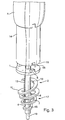
- FIG. 3 shows a closure system in the form of the elements of the closure according to the Figures 1 and 2 and a tool 14.
- This tool is tubular and has on its end face 15 two recesses 16 into which the cams 8 of the outer contact element 1 fit.
- the outer contact element 1 is displaceable on the tubular connecting element 4 in the axial direction, in a preferred embodiment, however, rotatably connected thereto.
- the connecting element 4 is longer in this embodiment before and during assembly than after assembly, where it is in a truncated form.
- a longitudinal groove may be provided in the connecting element 4, in which a radial inwardly directed projection (not shown) of the first connecting element protrudes.
- FIG. 3 shows the spirally formed inner contact element 2 in a relaxed state. It has the form of a helical spiral 17, in which the individual gears are offset from each other both in the axial and in the radial direction.
- the spiral is further formed as a flat spiral, ie in the compressed state, the individual strip-shaped windings are flat to form the disc-shaped inner abutment element side by side.
- the inner contact element 2 is integrally connected to the connecting element 4, for example jointly produced by injection molding.
- the connection 18 is preferably labile, so that the individual turns of the helical spiral 17 can apply to the tubular connecting element 4 as needed.
- FIG. 3 is still a flexible guide wire 19 shown by the opening 12 in the connecting element 4 and is passed through the tool 14.
- a guidewire is usually located in a percutaneous transluminal catheter intervention in the artery.
- it is provided to leave this guidewire after the procedure in the artery and to use it as a guide for centering the closure by the tubular connecting element 4 is pushed over the wire 19 and thus automatically guided to the opening 5 in the artery which is normally covered by the skin tissue or subcutaneous tissue 9 and is not so easy to find.
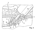
- FIG. 4 the attachment of the closure according to the invention to an arterial wall is shown.
- the insertion of the closure parts in the artery is oblique, because on the one hand, the guide wire 19 projects obliquely through the arterial wall 3 and continues in the artery and on the other hand is more space in the artery available through the oblique introduction.
- the insertion takes place by rotational movement on the tool 14, whereby the helical spiral 17 is screwed through the wall of the artery.
- the closure element 4 is attracted by the opening in the outer contact element, at the same time the helical spiral 17 is compressed to form the disc-shaped inner contact element 2.
- the tightening can be done directly by train on the extended closure element 4 or by pulling the thread 13. If the thickening or the locking element 6 of the connecting element 4 passed through the opening of the outer contact element 1 and snapped the locking connection, then the in FIG. 1 achieved state shown, wherein the two contact elements 1 and 2 abut resiliently and sealingly by the spring action of the coil 17 on the arterial wall 3.
- the supernumerary and in the Figures 3 and 4 shown part of the connecting element 4 can be cut off after pulling out the guide wire 19 and be squeezed simultaneously, so that a tight seal is present.
- the individual parts of the closure according to the invention are preferably made of resorbable plastics such as polymers and copolymers of ⁇ -hydroxy acids and the like, such as glycolide, lactide, trimethylene carbonate and caprolactone.
- resorbable plastics such as polymers and copolymers of ⁇ -hydroxy acids and the like, such as glycolide, lactide, trimethylene carbonate and caprolactone.
- the desired absorption time can be set. This is preferably chosen so that the absorption of the closure runs simultaneously with the healing of the opening in the arterial wall.
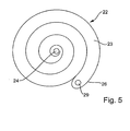
- an inner contact element 22 which is designed as a spiral 23, and a rod-shaped connecting element 24 connected thereto are shown.
- the connecting element 24 engages in the center of the spiral 23 and is solid. It may be provided with a thread 25 above the spiral.
- the free end 26 of the coil 23 is intended to be inserted first through a puncture opening 27 of a vessel wall 28. By rotation of the spiral 23, the entire spiral is then passed from outside to inside through the opening. In this case, the spiral can be rotated by means of the rod-shaped connecting piece 24.
- the inner abutment element is inserted substantially parallel to the vessel wall in the blood vessel, as in FIG. 6 is shown schematically.
- This embodiment is primarily suitable for use in puncture openings that are visible or can be visualized with aids. Then, the free end 26 can be inserted directly into the opening 27 in the vessel wall. If the opening 27 is not visible, then again a guide wire can be provided, which projects through the opening 27 in the vessel wall. At the free end 26 of the spiral coil 23, a corresponding Guide hole 29 may be provided, which is guided by the horizontal guide wire. With the help of the guide wire thus the opening 27 is found in the vessel wall 28. After insertion of the free end 26 of the guide wire can then be removed and the rest of the spiral 23 are screwed by rotation. As an outer contact element can be provided with internal thread in this embodiment, a perforated disc 30 which can be pushed over the rod-shaped connecting member 24 and screwed by rotation on the thread 25 to rest against the outer vessel wall (see. FIG. 7 ).
- an inner abutment element 42 is provided, which in turn is strip-shaped, but this time in the form of a flat meander 43 with adjacent strip portions.
- An odd number of strip portions 44 are provided. In this case, there are seven.
- the middle of the middle strip portion 45 is the attachment point for a connecting element 46 which is formed in this case as a flexible thread or wire.
- the introduction of the inner abutment member 42 begins by an opening in a vessel wall at a free end 47. Again, the free end may be provided with a guide opening 48 through which an already provided guide wire can be performed.
- the guide wire is removed and the meander-shaped contact element 42 is pushed in sections through the opening in the vessel wall until the other free end 49 of the meander has disappeared in the vessel.
- the strip portions 44 and 45 are separated by narrow cuts 50 from each other. Only at the ends of the dividing lines are narrow apertures 51 which facilitate the insertion of the strip through the puncture opening.
- the inner contact element 42 is centered. The attachment can then by attaching an external investment element or by other suitable measures.
Landscapes
- Health & Medical Sciences (AREA)
- Surgery (AREA)
- Life Sciences & Earth Sciences (AREA)
- Medical Informatics (AREA)
- Animal Behavior & Ethology (AREA)
- Engineering & Computer Science (AREA)
- Biomedical Technology (AREA)
- Heart & Thoracic Surgery (AREA)
- Cardiology (AREA)
- Molecular Biology (AREA)
- Nuclear Medicine, Radiotherapy & Molecular Imaging (AREA)
- General Health & Medical Sciences (AREA)
- Public Health (AREA)
- Veterinary Medicine (AREA)
- Surgical Instruments (AREA)
- Closures For Containers (AREA)
- Media Introduction/Drainage Providing Device (AREA)
Applications Claiming Priority (1)
| Application Number | Priority Date | Filing Date | Title |
|---|---|---|---|
| DE102008034534A DE102008034534A1 (de) | 2008-07-18 | 2008-07-18 | Punktionsverschluss zum Verschließen eines eine Punktionsöffnung aufweisenden Hohlorgans, insbesondere eines Blutgefäßes |
Publications (3)
| Publication Number | Publication Date |
|---|---|
| EP2145585A2 true EP2145585A2 (fr) | 2010-01-20 |
| EP2145585A3 EP2145585A3 (fr) | 2010-11-24 |
| EP2145585B1 EP2145585B1 (fr) | 2016-09-07 |
Family
ID=41059924
Family Applications (1)
| Application Number | Title | Priority Date | Filing Date |
|---|---|---|---|
| EP09009259.4A Not-in-force EP2145585B1 (fr) | 2008-07-18 | 2009-07-16 | Fermeture de ponction destiné à fermer un organe creux comprenant une ouverture de ponction, notamment un vaisseau sanguin |
Country Status (3)
| Country | Link |
|---|---|
| US (1) | US8672964B2 (fr) |
| EP (1) | EP2145585B1 (fr) |
| DE (1) | DE102008034534A1 (fr) |
Cited By (2)
| Publication number | Priority date | Publication date | Assignee | Title |
|---|---|---|---|---|
| WO2014031259A3 (fr) * | 2012-08-21 | 2014-04-17 | St. Jude Medical Puerto Rico Llc | Mécanisme d'obturation pour dispositifs de fermeture |
| CN105852919A (zh) * | 2016-04-22 | 2016-08-17 | 广东脉搏医疗科技有限公司 | 一种组织封闭器械 |
Families Citing this family (16)
| Publication number | Priority date | Publication date | Assignee | Title |
|---|---|---|---|---|
| US20100191168A1 (en) | 2009-01-29 | 2010-07-29 | Trustees Of Tufts College | Endovascular cerebrospinal fluid shunt |
| US8506593B2 (en) | 2010-04-11 | 2013-08-13 | Lap IP, Inc | Implantable biodegradable wound closure device and method |
| US10485524B2 (en) | 2011-10-25 | 2019-11-26 | Essential Medical, Inc. | Instrument and methods for surgically closing percutaneous punctures |
| US20140018631A1 (en) * | 2012-07-11 | 2014-01-16 | Covidien Lp | Surgical seal assembly including a guard member |
| US9757104B2 (en) | 2012-07-19 | 2017-09-12 | Essential Medical, Inc. | Multi-lumen tamper tube |
| US10639019B2 (en) | 2013-03-15 | 2020-05-05 | Arrow International, Inc. | Vascular closure devices and methods of use |
| US10448937B2 (en) | 2013-12-23 | 2019-10-22 | Essential Medical, Inc. | Vascular closure device |
| EP3998100A1 (fr) | 2014-01-15 | 2022-05-18 | Tufts Medical Center, Inc. | Système dérivation de liquide cérébro-spinal endovasculaire |
| US9737696B2 (en) * | 2014-01-15 | 2017-08-22 | Tufts Medical Center, Inc. | Endovascular cerebrospinal fluid shunt |
| CN107148293B (zh) | 2014-10-31 | 2020-08-11 | 西瑞维斯克有限责任公司 | 用于治疗脑积水的方法和系统 |
| US10555727B2 (en) | 2015-06-26 | 2020-02-11 | Essential Medical, Inc. | Vascular closure device with removable guide member |
| CN108136164B (zh) | 2015-10-30 | 2020-12-08 | 西瑞维斯克公司 | 用于治疗脑积水的系统和方法 |
| EP3525866B1 (fr) | 2016-10-11 | 2023-09-20 | CereVasc, Inc. | Méthodes et systèmes de traitement de l'hydrocéphalie |
| WO2019173784A1 (fr) | 2018-03-08 | 2019-09-12 | Cerevasc, Llc | Systèmes et procédés pour une administration de médicament minimalement invasive à un espace sous-arachnoïdien |
| US11759189B2 (en) * | 2018-12-12 | 2023-09-19 | Lap Iq, Inc. | Implantable tissue scaffold |
| US12390249B2 (en) | 2020-07-31 | 2025-08-19 | Teleflex Life Sciences Llc | Access sheath with valve assembly |
Citations (15)
| Publication number | Priority date | Publication date | Assignee | Title |
|---|---|---|---|---|
| US4744364A (en) | 1987-02-17 | 1988-05-17 | Intravascular Surgical Instruments, Inc. | Device for sealing percutaneous puncture in a vessel |
| WO1989011301A1 (fr) | 1988-05-16 | 1989-11-30 | Kensey Nash Corporation | Dispositif de fermeture d'un perçage percutane dans un vaisseau |
| US5350399A (en) | 1991-09-23 | 1994-09-27 | Jay Erlebacher | Percutaneous arterial puncture seal device and insertion tool therefore |
| EP0474752B1 (fr) | 1989-05-29 | 1995-06-28 | MUIJS VAN DE MOER, Wouter Matthijs | Ensemble d'occlusion pour obturer des ouvertures dans des vaisseaux sanguins |
| US5441517A (en) | 1991-11-08 | 1995-08-15 | Kensey Nash Corporation | Hemostatic puncture closure system and method of use |
| US5620461A (en) | 1989-05-29 | 1997-04-15 | Muijs Van De Moer; Wouter M. | Sealing device |
| DE19620620A1 (de) | 1996-05-22 | 1997-11-27 | Harren Ernst Diethelm | Punktionsverschluß |
| EP0776179B1 (fr) | 1994-08-18 | 1998-03-04 | Ernst-Diethelm Harren | Tampon pour orifice de ponction |
| EP0955901B1 (fr) | 1996-11-16 | 2003-04-23 | CAP Incorporated | Tampon d'obturation etanche pour orifice de ponction |
| US20030120291A1 (en) | 2001-12-26 | 2003-06-26 | Chin Albert K. | Temporary seal and method for facilitating anastomosis |
| US6764500B1 (en) | 1989-05-29 | 2004-07-20 | Kensey Nash Corporation | Sealing device |
| US20050033361A1 (en) | 2003-06-16 | 2005-02-10 | Galdonik Jason A. | Temporary hemostatic plug apparatus and method of use |
| US20050187564A1 (en) | 1999-12-23 | 2005-08-25 | Swaminathan Jayaraman | Occlusive coil manufacturing and delivery |
| US20060212047A1 (en) | 2001-09-06 | 2006-09-21 | Ryan Abbott | Systems and Methods for Treating Septal Defects |
| US20070135842A1 (en) | 1991-10-22 | 2007-06-14 | Kensey Nash Corporation | Sealing device |
Family Cites Families (13)
| Publication number | Priority date | Publication date | Assignee | Title |
|---|---|---|---|---|
| US4512338A (en) * | 1983-01-25 | 1985-04-23 | Balko Alexander B | Process for restoring patency to body vessels |
| US5527337A (en) * | 1987-06-25 | 1996-06-18 | Duke University | Bioabsorbable stent and method of making the same |
| US5582616A (en) * | 1994-08-05 | 1996-12-10 | Origin Medsystems, Inc. | Surgical helical fastener with applicator |
| US5879366A (en) * | 1996-12-20 | 1999-03-09 | W.L. Gore & Associates, Inc. | Self-expanding defect closure device and method of making and using |
| US6171329B1 (en) | 1994-12-19 | 2001-01-09 | Gore Enterprise Holdings, Inc. | Self-expanding defect closure device and method of making and using |
| DE19604817C2 (de) * | 1996-02-09 | 2003-06-12 | Pfm Prod Fuer Die Med Ag | Vorrichtung zum Verschließen von Defektöffnungen im menschlichen oder tierischen Körper |
| GB9614950D0 (en) * | 1996-07-16 | 1996-09-04 | Anson Medical Ltd | A ductus stent and delivery catheter |
| US5944750A (en) * | 1997-06-30 | 1999-08-31 | Eva Corporation | Method and apparatus for the surgical repair of aneurysms |
| US6113611A (en) * | 1998-05-28 | 2000-09-05 | Advanced Vascular Technologies, Llc | Surgical fastener and delivery system |
| EP1317213A2 (fr) * | 2000-09-01 | 2003-06-11 | Advanced Vascular Technologies LLC | Pince chirurgicale multiple et proc d associ |
| US6572626B1 (en) * | 2000-10-19 | 2003-06-03 | Ethicon Endo-Surgery, Inc. | Surgical instrument having a fastener delivery mechanism |
| US6447524B1 (en) * | 2000-10-19 | 2002-09-10 | Ethicon Endo-Surgery, Inc. | Fastener for hernia mesh fixation |
| US6537300B2 (en) * | 2001-05-30 | 2003-03-25 | Scimed Life Systems, Inc. | Implantable obstruction device for septal defects |
-
2008
- 2008-07-18 DE DE102008034534A patent/DE102008034534A1/de not_active Withdrawn
-
2009
- 2009-07-16 EP EP09009259.4A patent/EP2145585B1/fr not_active Not-in-force
- 2009-07-17 US US12/504,715 patent/US8672964B2/en not_active Expired - Fee Related
Patent Citations (18)
| Publication number | Priority date | Publication date | Assignee | Title |
|---|---|---|---|---|
| US4744364A (en) | 1987-02-17 | 1988-05-17 | Intravascular Surgical Instruments, Inc. | Device for sealing percutaneous puncture in a vessel |
| WO1989011301A1 (fr) | 1988-05-16 | 1989-11-30 | Kensey Nash Corporation | Dispositif de fermeture d'un perçage percutane dans un vaisseau |
| US6764500B1 (en) | 1989-05-29 | 2004-07-20 | Kensey Nash Corporation | Sealing device |
| EP0474752B1 (fr) | 1989-05-29 | 1995-06-28 | MUIJS VAN DE MOER, Wouter Matthijs | Ensemble d'occlusion pour obturer des ouvertures dans des vaisseaux sanguins |
| US5593422A (en) | 1989-05-29 | 1997-01-14 | Muijs Van De Moer; Wouter M. | Occlusion assembly for sealing openings in blood vessels and a method for sealing openings in blood vessels |
| US5620461A (en) | 1989-05-29 | 1997-04-15 | Muijs Van De Moer; Wouter M. | Sealing device |
| US7169168B2 (en) | 1989-05-29 | 2007-01-30 | Kensey Nash Corporation | Sealing device |
| US5916236A (en) | 1989-05-29 | 1999-06-29 | Kensey Nash Corporation | Occlusion assembly for sealing openings in blood vessels and a method for sealing openings in blood vessels |
| US5350399A (en) | 1991-09-23 | 1994-09-27 | Jay Erlebacher | Percutaneous arterial puncture seal device and insertion tool therefore |
| US20070135842A1 (en) | 1991-10-22 | 2007-06-14 | Kensey Nash Corporation | Sealing device |
| US5441517A (en) | 1991-11-08 | 1995-08-15 | Kensey Nash Corporation | Hemostatic puncture closure system and method of use |
| EP0776179B1 (fr) | 1994-08-18 | 1998-03-04 | Ernst-Diethelm Harren | Tampon pour orifice de ponction |
| DE19620620A1 (de) | 1996-05-22 | 1997-11-27 | Harren Ernst Diethelm | Punktionsverschluß |
| EP0955901B1 (fr) | 1996-11-16 | 2003-04-23 | CAP Incorporated | Tampon d'obturation etanche pour orifice de ponction |
| US20050187564A1 (en) | 1999-12-23 | 2005-08-25 | Swaminathan Jayaraman | Occlusive coil manufacturing and delivery |
| US20060212047A1 (en) | 2001-09-06 | 2006-09-21 | Ryan Abbott | Systems and Methods for Treating Septal Defects |
| US20030120291A1 (en) | 2001-12-26 | 2003-06-26 | Chin Albert K. | Temporary seal and method for facilitating anastomosis |
| US20050033361A1 (en) | 2003-06-16 | 2005-02-10 | Galdonik Jason A. | Temporary hemostatic plug apparatus and method of use |
Non-Patent Citations (1)
| Title |
|---|
| J.B. MADIGAN, L.A. RATNAM, A.M. BELLI, THE JOURNAL OF CARDIOVASCULAR SURGERY, vol. 48, 2007, pages 607 - 624 |
Cited By (4)
| Publication number | Priority date | Publication date | Assignee | Title |
|---|---|---|---|---|
| WO2014031259A3 (fr) * | 2012-08-21 | 2014-04-17 | St. Jude Medical Puerto Rico Llc | Mécanisme d'obturation pour dispositifs de fermeture |
| US9468429B2 (en) | 2012-08-21 | 2016-10-18 | St. Jude Medical Puerto Rico Llc | Sealing mechanism for closure devices |
| US10765414B2 (en) | 2012-08-21 | 2020-09-08 | Terumo Puerto Rico, L.L.C. | Sealing mechanism for closure devices |
| CN105852919A (zh) * | 2016-04-22 | 2016-08-17 | 广东脉搏医疗科技有限公司 | 一种组织封闭器械 |
Also Published As
| Publication number | Publication date |
|---|---|
| EP2145585B1 (fr) | 2016-09-07 |
| US20100016887A1 (en) | 2010-01-21 |
| DE102008034534A1 (de) | 2010-01-21 |
| EP2145585A3 (fr) | 2010-11-24 |
| US8672964B2 (en) | 2014-03-18 |
Similar Documents
| Publication | Publication Date | Title |
|---|---|---|
| EP2145585B1 (fr) | Fermeture de ponction destiné à fermer un organe creux comprenant une ouverture de ponction, notamment un vaisseau sanguin | |
| DE69821244T2 (de) | Verbindungseinrichtung für gefässe, leitungen, hohlräume oder hohle organe | |
| DE69332272T2 (de) | Vorrichtung zum nähen einer punktionsstelle in einem blutgefäss | |
| DE69722477T2 (de) | Vorrichtung zum Einsetzen einer chirurgischen Naht | |
| DE19628909C2 (de) | Verschluß | |
| DE69225720T2 (de) | Hämostatisches abdichtsystem einer punktur | |
| EP0604761B1 (fr) | Dispositif pour obstruer une ouverture dans un vaisseau | |
| DE60304464T2 (de) | Suburethrale Stützanordnung zur Behandlung der weiblichen stressbedingten Harninkontinenz | |
| EP0571422B1 (fr) | Implant en spirale pour conduits du corps | |
| DE69119378T2 (de) | Fasciaclip | |
| DE69932590T2 (de) | Nahtversteifung | |
| DE102010045367B4 (de) | Medizinische Vorrichtung zum Entfernen von Konkrementen | |
| DE60105302T2 (de) | Vaskuläre okklusionsvorrichtung, sowie gerät zu ihrer verwendung | |
| DE4306850C1 (de) | Implantat, insbesondere zum Verschluß von Trokareinstichstellen | |
| DE10000137A1 (de) | Implantat zum Verschließen von Defektöffnungen im menschlichen oder tierischen Körper | |
| DE3640745A1 (de) | Katheter zum herstellen oder erweitern von verbindungen zu oder zwischen koerperhohlraeumen | |
| EP4103105B1 (fr) | Système pour l'implantation d'un implant médical dans le corps humain ou animal | |
| DE69714042T2 (de) | Versteifendes implantat für organwege | |
| DE102007061931A1 (de) | Medizinisches Implantat | |
| EP3073935B1 (fr) | Système servant à relier un implant médical à un auxiliaire d'insertion | |
| DE602004004281T2 (de) | Verschlussvorrichtung zum Abdichten einer Punktion in einem Blutgefäss | |
| EP1159919A2 (fr) | Dispositif de fermeture d'une ouverture dans une couche de tissu | |
| DE102015102542A1 (de) | Endoskopische Schneideinrichtung zum Freischneiden einer mit einer Halteplatte versehenen Sonde | |
| DE69206419T2 (de) | Intravenöse vorrichtung zum vollständigen oder teilweisen abflachen einer vene. | |
| DE20009815U1 (de) | Vorrichtung zum Verschliessen einer Öffnung in einer Gewebeschicht |
Legal Events
| Date | Code | Title | Description |
|---|---|---|---|
| PUAI | Public reference made under article 153(3) epc to a published international application that has entered the european phase |
Free format text: ORIGINAL CODE: 0009012 |
|
| AK | Designated contracting states |
Kind code of ref document: A2 Designated state(s): AT BE BG CH CY CZ DE DK EE ES FI FR GB GR HR HU IE IS IT LI LT LU LV MC MK MT NL NO PL PT RO SE SI SK SM TR |
|
| AX | Request for extension of the european patent |
Extension state: AL BA RS |
|
| PUAL | Search report despatched |
Free format text: ORIGINAL CODE: 0009013 |
|
| AK | Designated contracting states |
Kind code of ref document: A3 Designated state(s): AT BE BG CH CY CZ DE DK EE ES FI FR GB GR HR HU IE IS IT LI LT LU LV MC MK MT NL NO PL PT RO SE SI SK SM TR |
|
| AX | Request for extension of the european patent |
Extension state: AL BA RS |
|
| 17P | Request for examination filed |
Effective date: 20110513 |
|
| GRAP | Despatch of communication of intention to grant a patent |
Free format text: ORIGINAL CODE: EPIDOSNIGR1 |
|
| INTG | Intention to grant announced |
Effective date: 20160219 |
|
| GRAS | Grant fee paid |
Free format text: ORIGINAL CODE: EPIDOSNIGR3 |
|
| GRAA | (expected) grant |
Free format text: ORIGINAL CODE: 0009210 |
|
| AK | Designated contracting states |
Kind code of ref document: B1 Designated state(s): AT BE BG CH CY CZ DE DK EE ES FI FR GB GR HR HU IE IS IT LI LT LU LV MC MK MT NL NO PL PT RO SE SI SK SM TR |
|
| REG | Reference to a national code |
Ref country code: GB Ref legal event code: FG4D Free format text: NOT ENGLISH |
|
| REG | Reference to a national code |
Ref country code: CH Ref legal event code: EP |
|
| REG | Reference to a national code |
Ref country code: IE Ref legal event code: FG4D Free format text: LANGUAGE OF EP DOCUMENT: GERMAN |
|
| REG | Reference to a national code |
Ref country code: AT Ref legal event code: REF Ref document number: 826100 Country of ref document: AT Kind code of ref document: T Effective date: 20161015 |
|
| REG | Reference to a national code |
Ref country code: DE Ref legal event code: R096 Ref document number: 502009013043 Country of ref document: DE |
|
| REG | Reference to a national code |
Ref country code: LT Ref legal event code: MG4D |
|
| REG | Reference to a national code |
Ref country code: NL Ref legal event code: MP Effective date: 20160907 |
|
| PG25 | Lapsed in a contracting state [announced via postgrant information from national office to epo] |
Ref country code: LT Free format text: LAPSE BECAUSE OF FAILURE TO SUBMIT A TRANSLATION OF THE DESCRIPTION OR TO PAY THE FEE WITHIN THE PRESCRIBED TIME-LIMIT Effective date: 20160907 Ref country code: NO Free format text: LAPSE BECAUSE OF FAILURE TO SUBMIT A TRANSLATION OF THE DESCRIPTION OR TO PAY THE FEE WITHIN THE PRESCRIBED TIME-LIMIT Effective date: 20161207 Ref country code: FI Free format text: LAPSE BECAUSE OF FAILURE TO SUBMIT A TRANSLATION OF THE DESCRIPTION OR TO PAY THE FEE WITHIN THE PRESCRIBED TIME-LIMIT Effective date: 20160907 Ref country code: HR Free format text: LAPSE BECAUSE OF FAILURE TO SUBMIT A TRANSLATION OF THE DESCRIPTION OR TO PAY THE FEE WITHIN THE PRESCRIBED TIME-LIMIT Effective date: 20160907 |
|
| PG25 | Lapsed in a contracting state [announced via postgrant information from national office to epo] |
Ref country code: ES Free format text: LAPSE BECAUSE OF FAILURE TO SUBMIT A TRANSLATION OF THE DESCRIPTION OR TO PAY THE FEE WITHIN THE PRESCRIBED TIME-LIMIT Effective date: 20160907 Ref country code: LV Free format text: LAPSE BECAUSE OF FAILURE TO SUBMIT A TRANSLATION OF THE DESCRIPTION OR TO PAY THE FEE WITHIN THE PRESCRIBED TIME-LIMIT Effective date: 20160907 Ref country code: NL Free format text: LAPSE BECAUSE OF FAILURE TO SUBMIT A TRANSLATION OF THE DESCRIPTION OR TO PAY THE FEE WITHIN THE PRESCRIBED TIME-LIMIT Effective date: 20160907 Ref country code: SE Free format text: LAPSE BECAUSE OF FAILURE TO SUBMIT A TRANSLATION OF THE DESCRIPTION OR TO PAY THE FEE WITHIN THE PRESCRIBED TIME-LIMIT Effective date: 20160907 Ref country code: GR Free format text: LAPSE BECAUSE OF FAILURE TO SUBMIT A TRANSLATION OF THE DESCRIPTION OR TO PAY THE FEE WITHIN THE PRESCRIBED TIME-LIMIT Effective date: 20161208 |
|
| PG25 | Lapsed in a contracting state [announced via postgrant information from national office to epo] |
Ref country code: RO Free format text: LAPSE BECAUSE OF FAILURE TO SUBMIT A TRANSLATION OF THE DESCRIPTION OR TO PAY THE FEE WITHIN THE PRESCRIBED TIME-LIMIT Effective date: 20160907 Ref country code: EE Free format text: LAPSE BECAUSE OF FAILURE TO SUBMIT A TRANSLATION OF THE DESCRIPTION OR TO PAY THE FEE WITHIN THE PRESCRIBED TIME-LIMIT Effective date: 20160907 |
|
| PG25 | Lapsed in a contracting state [announced via postgrant information from national office to epo] |
Ref country code: IS Free format text: LAPSE BECAUSE OF FAILURE TO SUBMIT A TRANSLATION OF THE DESCRIPTION OR TO PAY THE FEE WITHIN THE PRESCRIBED TIME-LIMIT Effective date: 20170107 Ref country code: SK Free format text: LAPSE BECAUSE OF FAILURE TO SUBMIT A TRANSLATION OF THE DESCRIPTION OR TO PAY THE FEE WITHIN THE PRESCRIBED TIME-LIMIT Effective date: 20160907 Ref country code: BG Free format text: LAPSE BECAUSE OF FAILURE TO SUBMIT A TRANSLATION OF THE DESCRIPTION OR TO PAY THE FEE WITHIN THE PRESCRIBED TIME-LIMIT Effective date: 20161207 Ref country code: CZ Free format text: LAPSE BECAUSE OF FAILURE TO SUBMIT A TRANSLATION OF THE DESCRIPTION OR TO PAY THE FEE WITHIN THE PRESCRIBED TIME-LIMIT Effective date: 20160907 Ref country code: PL Free format text: LAPSE BECAUSE OF FAILURE TO SUBMIT A TRANSLATION OF THE DESCRIPTION OR TO PAY THE FEE WITHIN THE PRESCRIBED TIME-LIMIT Effective date: 20160907 Ref country code: PT Free format text: LAPSE BECAUSE OF FAILURE TO SUBMIT A TRANSLATION OF THE DESCRIPTION OR TO PAY THE FEE WITHIN THE PRESCRIBED TIME-LIMIT Effective date: 20170109 Ref country code: SM Free format text: LAPSE BECAUSE OF FAILURE TO SUBMIT A TRANSLATION OF THE DESCRIPTION OR TO PAY THE FEE WITHIN THE PRESCRIBED TIME-LIMIT Effective date: 20160907 |
|
| REG | Reference to a national code |
Ref country code: DE Ref legal event code: R097 Ref document number: 502009013043 Country of ref document: DE |
|
| PG25 | Lapsed in a contracting state [announced via postgrant information from national office to epo] |
Ref country code: IT Free format text: LAPSE BECAUSE OF FAILURE TO SUBMIT A TRANSLATION OF THE DESCRIPTION OR TO PAY THE FEE WITHIN THE PRESCRIBED TIME-LIMIT Effective date: 20160907 |
|
| PLBE | No opposition filed within time limit |
Free format text: ORIGINAL CODE: 0009261 |
|
| STAA | Information on the status of an ep patent application or granted ep patent |
Free format text: STATUS: NO OPPOSITION FILED WITHIN TIME LIMIT |
|
| PG25 | Lapsed in a contracting state [announced via postgrant information from national office to epo] |
Ref country code: DK Free format text: LAPSE BECAUSE OF FAILURE TO SUBMIT A TRANSLATION OF THE DESCRIPTION OR TO PAY THE FEE WITHIN THE PRESCRIBED TIME-LIMIT Effective date: 20160907 |
|
| 26N | No opposition filed |
Effective date: 20170608 |
|
| PG25 | Lapsed in a contracting state [announced via postgrant information from national office to epo] |
Ref country code: SI Free format text: LAPSE BECAUSE OF FAILURE TO SUBMIT A TRANSLATION OF THE DESCRIPTION OR TO PAY THE FEE WITHIN THE PRESCRIBED TIME-LIMIT Effective date: 20160907 |
|
| REG | Reference to a national code |
Ref country code: DE Ref legal event code: R119 Ref document number: 502009013043 Country of ref document: DE |
|
| REG | Reference to a national code |
Ref country code: CH Ref legal event code: PL |
|
| GBPC | Gb: european patent ceased through non-payment of renewal fee |
Effective date: 20170716 |
|
| REG | Reference to a national code |
Ref country code: IE Ref legal event code: MM4A |
|
| REG | Reference to a national code |
Ref country code: FR Ref legal event code: ST Effective date: 20180330 |
|
| PG25 | Lapsed in a contracting state [announced via postgrant information from national office to epo] |
Ref country code: IE Free format text: LAPSE BECAUSE OF NON-PAYMENT OF DUE FEES Effective date: 20170716 Ref country code: GB Free format text: LAPSE BECAUSE OF NON-PAYMENT OF DUE FEES Effective date: 20170716 Ref country code: CH Free format text: LAPSE BECAUSE OF NON-PAYMENT OF DUE FEES Effective date: 20170731 Ref country code: DE Free format text: LAPSE BECAUSE OF NON-PAYMENT OF DUE FEES Effective date: 20180201 Ref country code: LI Free format text: LAPSE BECAUSE OF NON-PAYMENT OF DUE FEES Effective date: 20170731 |
|
| REG | Reference to a national code |
Ref country code: BE Ref legal event code: MM Effective date: 20170731 |
|
| PG25 | Lapsed in a contracting state [announced via postgrant information from national office to epo] |
Ref country code: FR Free format text: LAPSE BECAUSE OF NON-PAYMENT OF DUE FEES Effective date: 20170731 |
|
| PG25 | Lapsed in a contracting state [announced via postgrant information from national office to epo] |
Ref country code: LU Free format text: LAPSE BECAUSE OF NON-PAYMENT OF DUE FEES Effective date: 20170716 |
|
| PG25 | Lapsed in a contracting state [announced via postgrant information from national office to epo] |
Ref country code: BE Free format text: LAPSE BECAUSE OF NON-PAYMENT OF DUE FEES Effective date: 20170731 |
|
| REG | Reference to a national code |
Ref country code: AT Ref legal event code: MM01 Ref document number: 826100 Country of ref document: AT Kind code of ref document: T Effective date: 20170716 |
|
| PG25 | Lapsed in a contracting state [announced via postgrant information from national office to epo] |
Ref country code: MT Free format text: LAPSE BECAUSE OF FAILURE TO SUBMIT A TRANSLATION OF THE DESCRIPTION OR TO PAY THE FEE WITHIN THE PRESCRIBED TIME-LIMIT Effective date: 20160907 |
|
| PG25 | Lapsed in a contracting state [announced via postgrant information from national office to epo] |
Ref country code: AT Free format text: LAPSE BECAUSE OF NON-PAYMENT OF DUE FEES Effective date: 20170716 |
|
| PG25 | Lapsed in a contracting state [announced via postgrant information from national office to epo] |
Ref country code: HU Free format text: LAPSE BECAUSE OF FAILURE TO SUBMIT A TRANSLATION OF THE DESCRIPTION OR TO PAY THE FEE WITHIN THE PRESCRIBED TIME-LIMIT; INVALID AB INITIO Effective date: 20090716 Ref country code: MC Free format text: LAPSE BECAUSE OF FAILURE TO SUBMIT A TRANSLATION OF THE DESCRIPTION OR TO PAY THE FEE WITHIN THE PRESCRIBED TIME-LIMIT Effective date: 20160907 |
|
| PG25 | Lapsed in a contracting state [announced via postgrant information from national office to epo] |
Ref country code: CY Free format text: LAPSE BECAUSE OF NON-PAYMENT OF DUE FEES Effective date: 20160907 |
|
| PG25 | Lapsed in a contracting state [announced via postgrant information from national office to epo] |
Ref country code: MK Free format text: LAPSE BECAUSE OF FAILURE TO SUBMIT A TRANSLATION OF THE DESCRIPTION OR TO PAY THE FEE WITHIN THE PRESCRIBED TIME-LIMIT Effective date: 20160907 |
|
| PG25 | Lapsed in a contracting state [announced via postgrant information from national office to epo] |
Ref country code: TR Free format text: LAPSE BECAUSE OF FAILURE TO SUBMIT A TRANSLATION OF THE DESCRIPTION OR TO PAY THE FEE WITHIN THE PRESCRIBED TIME-LIMIT Effective date: 20160907 |