EP2145662B1 - Entaschungsanlage für Flugasche und Verfahren zum Betrieb der Anlage - Google Patents
Entaschungsanlage für Flugasche und Verfahren zum Betrieb der Anlage Download PDFInfo
- Publication number
- EP2145662B1 EP2145662B1 EP09008242A EP09008242A EP2145662B1 EP 2145662 B1 EP2145662 B1 EP 2145662B1 EP 09008242 A EP09008242 A EP 09008242A EP 09008242 A EP09008242 A EP 09008242A EP 2145662 B1 EP2145662 B1 EP 2145662B1
- Authority
- EP
- European Patent Office
- Prior art keywords
- funnels
- dust
- ash removal
- pressure tanks
- removal installation
- Prior art date
- Legal status (The legal status is an assumption and is not a legal conclusion. Google has not performed a legal analysis and makes no representation as to the accuracy of the status listed.)
- Active
Links
Images


Classifications
-
- B—PERFORMING OPERATIONS; TRANSPORTING
- B01—PHYSICAL OR CHEMICAL PROCESSES OR APPARATUS IN GENERAL
- B01D—SEPARATION
- B01D46/00—Filters or filtering processes specially modified for separating dispersed particles from gases or vapours
- B01D46/42—Auxiliary equipment or operation thereof
- B01D46/48—Removing dust other than cleaning filters, e.g. by using collecting trays
-
- B—PERFORMING OPERATIONS; TRANSPORTING
- B01—PHYSICAL OR CHEMICAL PROCESSES OR APPARATUS IN GENERAL
- B01D—SEPARATION
- B01D45/00—Separating dispersed particles from gases or vapours by gravity, inertia, or centrifugal forces
- B01D45/18—Cleaning-out devices
-
- B—PERFORMING OPERATIONS; TRANSPORTING
- B65—CONVEYING; PACKING; STORING; HANDLING THIN OR FILAMENTARY MATERIAL
- B65G—TRANSPORT OR STORAGE DEVICES, e.g. CONVEYORS FOR LOADING OR TIPPING, SHOP CONVEYOR SYSTEMS OR PNEUMATIC TUBE CONVEYORS
- B65G53/00—Conveying materials in bulk through troughs, pipes or tubes by floating the materials or by flow of gas, liquid or foam
- B65G53/34—Details
- B65G53/36—Arrangements of containers
-
- F—MECHANICAL ENGINEERING; LIGHTING; HEATING; WEAPONS; BLASTING
- F23—COMBUSTION APPARATUS; COMBUSTION PROCESSES
- F23J—REMOVAL OR TREATMENT OF COMBUSTION PRODUCTS OR COMBUSTION RESIDUES; FLUES
- F23J15/00—Arrangements of devices for treating smoke or fumes
- F23J15/02—Arrangements of devices for treating smoke or fumes of purifiers, e.g. for removing noxious material
- F23J15/022—Arrangements of devices for treating smoke or fumes of purifiers, e.g. for removing noxious material for removing solid particulate material from the gasflow
- F23J15/025—Arrangements of devices for treating smoke or fumes of purifiers, e.g. for removing noxious material for removing solid particulate material from the gasflow using filters
Definitions
- the invention relates to a deashing system for fly ash according to claim 1 and to a method of the system according to claim 10.
- the dedusting of flue gases or deashing for fly ash, such as in a coal-fired power plant has an array of filter units, which are traversed by the flue gas.
- An example of an arrangement of filter units is shown in FIG US 4,205,931 .
- the collected dust is discharged into funnel-shaped containers. From there, the dust is transported by means of conveyors into pressure vessels. In the pressure vessels accumulated dust is discharged by means of conveying air to a suitable silo. During this discharge process, a valve arrangement between the funnel and the pressure vessel is closed. It is understood that during the emptying of the pressure vessel (delivery cycle) no dust can be entered into the pressure vessel. Therefore, the access to the pressure vessel must be blocked during the emptying process.
- the invention has for its object to provide a dedusting or ash removal system for fly ash, which has a low expenditure on equipment and a low overall height.
- pressure vessels are arranged only under the rear field seen in the flow direction of the flue gas, and these funnels are connected without buffer container almost directly via valves to a pressure vessel.
- the funnels of the other fields are connected directly via valves with a pneumatic conveyor trough, the cross-section of which can increase in the flow direction of the flue gas and which has a slight downward slope towards the pressure vessel.
- the slope of the pneumatic conveyor trough is approximately between 1 and 6 degrees.
- a respective conveying trough must be guided by the upstream funnels and one of the downstream funnels to the respective pressure vessel, wherein the gradient in the grooves is naturally directed opposite.
- the fluidizing air is heated for the pneumatic conveying trough.
- the pressure vessel of each funnel row is connected via a vent line to the funnel, which is the first seen in the flow direction.
- the conveyor trough between the pressure vessels and the funnels also connected to the vent line. In this way, a proper ventilation will be included, without the risk that dust is introduced into the environment.
- the vent line is heated and / or thermally insulated.
- the inventive solution according to claim 10 provides a method for operating a deashing plant of the type mentioned above.
- the dust is stacked during the pressure vessel conveying cycles in the conveyor troughs, which are connected below the funnels of the rows of funnels with the funnels via valves, whereby the dust in the sloping conveyor trough is fluidized so that it can be easily conveyed into the pressure vessels , From the hoppers immediately above the pressure vessels, the dust is introduced substantially directly into the pressure vessels without the interposition of buffer tanks or the like.
- the dust is preferably discharged in groups according to a further embodiment of the invention. During this discharge, the dust can only be entered into the pressure vessels of another group.
- the introduction of dust into pressure vessels and the discharge of dust from the pressure vessels can be carried out substantially intermittently, with only a brief interruption takes place when switching from the entry into the discharge operation.
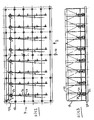
- a field of rectangular in cross-section funnels 10 can be seen, which are arranged in fields 12 and rows 14. Eight funnels 10 each form an electric field and five funnels one row. The upper ends of the funnels 10 are at the same height and close together.
- the field of the funnels 10 is located below a filter assembly, not shown, which consists for example of electrostatic filters through which flue gas flows. The flow direction of the flue gas is indicated by arrow 16. The dust deposited in the filter assembly is in the individual funnels 10 passed.
- a filter assembly not shown, which consists for example of electrostatic filters through which flue gas flows.
- the flow direction of the flue gas is indicated by arrow 16.
- the dust deposited in the filter assembly is in the individual funnels 10 passed.
- the funnels 10 are arranged on a foundation plate 20 by means of individual stands or supports 18.
- the rear fields of the funnels 10 in the flow direction of the gas are assigned to pressure vessels 22. They are each below a funnel 10 of this field with the interposition of a vent tank 24. Below each row 14 of the funnel 10, a pneumatic conveying trough 26 is further arranged, which is connected via the vent tank 24 to the pressure vessel 22. This also turns out Fig. 2 remove.
- a vent trough 28 Arranged next to or above the conveyor trough 26 is a vent trough 28, which is also connected to the deaeration tank 24 and communicates with the funnels 10 of the first panel in the upper area.
- the conveyor trough 26 is also connected between the funnels 10 via a connecting line piece 30 with the vent groove 28.
- the pressure vessels 22 are connected via a vent line 34 to the vent tank 24.
- FIGS. 1 and 2 shows that four pressure vessels of the last field each form a pressure vessel group.
- Fig. 1 left group is connected to a common delivery line 36 and the in Fig. 1 right group of the four pressure vessels is connected to a delivery line 39.
- Both delivery lines 36, 39 are connected to a common delivery line 38.
- FIGS. 5 to 7 It can be seen that below the funnel 10 gate valves 40 are arranged, which in the arrangement according to the FIGS. 5 and 6 a double lock 42 follows, according to Fig. 5 is connected via a compensator 46 with the vent tank 24. Between the vent tank 24 and the pressure vessel, a further gate valve 48, a compensator 50 and another valve 52 are arranged.
- the supply to the pressure vessels 22 is interrupted.
- the valve 52 is closed in this case.
- the material therefore collects in the conveyor trough 26.
- the procedure is such that a first group of pressure vessels 22 is supplied with compressed air, which is not shown here.
- the material is discharged from the pressure vessels 22, depending on the control either via the delivery line 36 or the delivery line 39.
- the supply of material is blocked during the discharge from the respective pressure vessels.
- a supply of material can still take place, so that a supply and removal of dust is ensured almost continuously.
- the described vent ensures that air can escape from the pressure vessels 22 and the conveyor troughs 26.
Landscapes
- Engineering & Computer Science (AREA)
- Chemical & Material Sciences (AREA)
- Chemical Kinetics & Catalysis (AREA)
- Mechanical Engineering (AREA)
- General Engineering & Computer Science (AREA)
- Air Transport Of Granular Materials (AREA)
- Filling Or Emptying Of Bunkers, Hoppers, And Tanks (AREA)
- Incineration Of Waste (AREA)
- Fluidized-Bed Combustion And Resonant Combustion (AREA)
Priority Applications (2)
| Application Number | Priority Date | Filing Date | Title |
|---|---|---|---|
| EP12002890A EP2481463A1 (de) | 2008-07-15 | 2009-06-24 | Entaschungsanlage für Flugasche und Verfahren zum Betrieb der Anlage |
| PL09008242T PL2145662T3 (pl) | 2008-07-15 | 2009-06-24 | Instalacja do odpopielania dla popiołu lotnego i sposób eksploatacji instalacji |
Applications Claiming Priority (1)
| Application Number | Priority Date | Filing Date | Title |
|---|---|---|---|
| DE102008033266A DE102008033266B4 (de) | 2008-07-15 | 2008-07-15 | Entaschungsanlage für Flugasche und Verfahren zum Betrieb der Anlage |
Related Child Applications (1)
| Application Number | Title | Priority Date | Filing Date |
|---|---|---|---|
| EP12002890.7 Division-Into | 2012-04-24 |
Publications (2)
| Publication Number | Publication Date |
|---|---|
| EP2145662A1 EP2145662A1 (de) | 2010-01-20 |
| EP2145662B1 true EP2145662B1 (de) | 2012-12-12 |
Family
ID=40299425
Family Applications (2)
| Application Number | Title | Priority Date | Filing Date |
|---|---|---|---|
| EP09008242A Active EP2145662B1 (de) | 2008-07-15 | 2009-06-24 | Entaschungsanlage für Flugasche und Verfahren zum Betrieb der Anlage |
| EP12002890A Withdrawn EP2481463A1 (de) | 2008-07-15 | 2009-06-24 | Entaschungsanlage für Flugasche und Verfahren zum Betrieb der Anlage |
Family Applications After (1)
| Application Number | Title | Priority Date | Filing Date |
|---|---|---|---|
| EP12002890A Withdrawn EP2481463A1 (de) | 2008-07-15 | 2009-06-24 | Entaschungsanlage für Flugasche und Verfahren zum Betrieb der Anlage |
Country Status (6)
| Country | Link |
|---|---|
| EP (2) | EP2145662B1 (pl) |
| DE (2) | DE202008011210U1 (pl) |
| PL (1) | PL2145662T3 (pl) |
| RU (1) | RU2422727C2 (pl) |
| UA (1) | UA99603C2 (pl) |
| ZA (1) | ZA200904895B (pl) |
Families Citing this family (3)
| Publication number | Priority date | Publication date | Assignee | Title |
|---|---|---|---|---|
| CN114408581A (zh) * | 2022-02-16 | 2022-04-29 | 红塔烟草(集团)有限责任公司 | 烟片物料由振筛出口转送负压管道的中继传输装置 |
| AT525912B1 (de) * | 2022-08-03 | 2023-09-15 | Scheuch Man Holding Gmbh | Verfahren zur Zementherstellung mit Schleusenvorrichtungen, Filteranlage und Zementherstellungsanlage |
| CN120081191A (zh) * | 2025-04-21 | 2025-06-03 | 三元控股集团杭州热电有限公司 | 一种飞灰气力输送系统 |
Family Cites Families (14)
| Publication number | Priority date | Publication date | Assignee | Title |
|---|---|---|---|---|
| GB191404454A (en) * | 1914-02-20 | 1915-02-22 | Hubert Cecil Booth | Improved Means for the Removal by Suction of Dust, Ashes, and the like from Flues, Furnaces and the like, applicable also to other Allied Purposes. |
| GB228747A (en) * | 1924-04-14 | 1925-02-12 | Ferdinand Wreesmann | Method and device for evaporating the volatile constituents of solutions, emulsions and suspensions |
| GB383683A (en) * | 1930-09-15 | 1932-11-24 | Frank Berry Allen | Improved apparatus for discharging materials such as dust from hoppers and the like |
| US2496281A (en) * | 1944-07-12 | 1950-02-07 | Whiting Corp | Fly ash and dust collector |
| DE1123789B (de) * | 1959-10-08 | 1962-02-15 | Peters Ag Claudius | Verfahren und Einrichtung zum Trocknen und anschliessenden pneumatischen Foerdern der bei Dampfkesselfeuerungen u. dgl. mit Nassentschlacker anfallenden Schlacke |
| FR1327967A (fr) * | 1962-05-03 | 1963-05-24 | Mcnamee Ind Pty Ltd | Dispositif de commande actionné par le vide et destiné notamment à une installation de dépoussiérage |
| SU856509A1 (ru) * | 1978-07-17 | 1981-08-23 | Всесоюзный Дважды Ордена Трудового Красного Знамени Теплотехнический Научно-Исследовательский Институт Им. Ф.Э. Дзержинского | Мокрый золоуловитель |
| US4205931A (en) * | 1978-12-04 | 1980-06-03 | Combustion Engineering, Inc. | Pneumatic ash transporting and containing system |
| DE3305585C2 (de) * | 1983-02-18 | 1986-10-16 | Didier-Werke Ag, 6200 Wiesbaden | Filteranlage zum Reinigen von heißen Rohgasen |
| US5096598A (en) * | 1990-02-26 | 1992-03-17 | Sullair Corporation | Pressurized purging of a liquid drain for a vacuum system |
| DE9404902U1 (de) * | 1994-03-18 | 1994-05-19 | Veag Vereinigte Energiewerke Ag, 12681 Berlin | Anordnung zur Dosierung von Filterasche aus dem Trichter eines Elektrofilters |
| EP1295822A1 (de) * | 2001-09-21 | 2003-03-26 | BMH Claudius Peters GmbH | Pneumatische Fördervorrichtung und -verfahren |
| RU2306485C1 (ru) * | 2006-06-05 | 2007-09-20 | Государственное образовательное учреждение высшего профессионального образования "Южно-Уральский государственный университет" ЮУрГУ | Золоуловитель |
| DE102007054212A1 (de) * | 2007-11-12 | 2009-05-14 | Grochowski, Horst, Dr. | Fluidbehandlungsanlage mit parallel betriebenen Schüttgutbetten sowie Verfahren zum Betreiben einer solchen Anlage |
-
2008
- 2008-07-15 DE DE202008011210U patent/DE202008011210U1/de not_active Expired - Lifetime
- 2008-07-15 DE DE102008033266A patent/DE102008033266B4/de not_active Withdrawn - After Issue
-
2009
- 2009-06-24 PL PL09008242T patent/PL2145662T3/pl unknown
- 2009-06-24 EP EP09008242A patent/EP2145662B1/de active Active
- 2009-06-24 EP EP12002890A patent/EP2481463A1/de not_active Withdrawn
- 2009-07-13 RU RU2009126464/03A patent/RU2422727C2/ru active
- 2009-07-13 ZA ZA200904895A patent/ZA200904895B/en unknown
- 2009-07-14 UA UAA200907405A patent/UA99603C2/ru unknown
Also Published As
| Publication number | Publication date |
|---|---|
| ZA200904895B (en) | 2010-03-31 |
| RU2009126464A (ru) | 2011-01-20 |
| EP2481463A1 (de) | 2012-08-01 |
| EP2145662A1 (de) | 2010-01-20 |
| DE102008033266A1 (de) | 2010-01-21 |
| DE102008033266B4 (de) | 2010-09-16 |
| UA99603C2 (ru) | 2012-09-10 |
| PL2145662T3 (pl) | 2013-05-31 |
| RU2422727C2 (ru) | 2011-06-27 |
| DE202008011210U1 (de) | 2009-01-29 |
Similar Documents
| Publication | Publication Date | Title |
|---|---|---|
| EP0574675B1 (de) | Wanderbettreaktoranlage | |
| WO2009097969A1 (de) | Verfahren und vorrichtung zur aufnahme und übergabe von fein- bis grobkörnigen feststoffen aus einem behälter in ein system höheren druckes | |
| EP2558215B1 (de) | Mehrdeck-luftsetzmaschine | |
| EP0270531B1 (de) | Wanderbettreaktor | |
| EP2145662B1 (de) | Entaschungsanlage für Flugasche und Verfahren zum Betrieb der Anlage | |
| DE2646130B2 (de) | Druckluftfördereinrichtung | |
| DE3034163A1 (de) | Verfahren zum gesteuerten foerdern von schuettgut und einrichtung zur durchfuehrung des verfahrens | |
| DD278946A5 (de) | Schacht mit einem wanderbett aus rieselfaehigem gut | |
| EP1529561B1 (de) | Verfahren, Vorrichtung und Anlage zum Behandeln von Fluiden an mindestens einer Schüttgutschicht | |
| DE2936198A1 (de) | Vorrichtung zur aufhaldung von schuettguetern unterschiedlicher korngroesse | |
| DE3013645A1 (de) | Verfahren und vorrichtung fuer die zufuehrung von teilchen in eine wirbelschicht | |
| EP3328222B1 (de) | Entleermagazin und verfahren zum entleeren von mit stabförmigen artikeln der tabak verarbeitenden industrie gefüllten schragen | |
| DE202011000826U1 (de) | Anlage zum Reinigen von industriellen Abgasen | |
| DE2500784C3 (de) | Doppelstock-Mischsilo | |
| EP3733314B1 (de) | Ausschleusevorrichtung | |
| DE2829149C2 (pl) | ||
| EP0362589B1 (de) | Vorrichtung mit Schüttschichtfiltern zur Reinigung von Rohgas | |
| EP0556368B1 (de) | Schüttgutreaktor | |
| DE19618377A1 (de) | Vorrichtung zum Reinigen staubhaltiger Luft und Verfahren zum Abwerfen von abgesammeltem Staub | |
| DE19942335A1 (de) | Verfahren, Vorrichtung und Anlage zum Behandeln von Fluiden an mindestens einer Schüttgutschicht | |
| DE4142916C1 (en) | Conveying solid particles over long distance - involves conveying pipe projecting through perforated distribution plate inside distribution container and small conveying pipes in upper part | |
| DE3617352A1 (de) | Druckluftfoerder- und dosiereinrichtung | |
| DE102007054212A1 (de) | Fluidbehandlungsanlage mit parallel betriebenen Schüttgutbetten sowie Verfahren zum Betreiben einer solchen Anlage | |
| DE1482427C (de) | Steigronrwindsichter mit Zickzackkanal | |
| DE1272821B (de) | Vorrichtung zum pneumatischen Verteilen von Schuettguetern |
Legal Events
| Date | Code | Title | Description |
|---|---|---|---|
| PUAI | Public reference made under article 153(3) epc to a published international application that has entered the european phase |
Free format text: ORIGINAL CODE: 0009012 |
|
| AK | Designated contracting states |
Kind code of ref document: A1 Designated state(s): AT BE BG CH CY CZ DE DK EE ES FI FR GB GR HR HU IE IS IT LI LT LU LV MC MK MT NL NO PL PT RO SE SI SK TR |
|
| AX | Request for extension of the european patent |
Extension state: AL BA RS |
|
| 17P | Request for examination filed |
Effective date: 20100330 |
|
| 17Q | First examination report despatched |
Effective date: 20100429 |
|
| RAP1 | Party data changed (applicant data changed or rights of an application transferred) |
Owner name: FLSMIDTH A/S |
|
| REG | Reference to a national code |
Ref country code: DE Ref legal event code: R079 Ref document number: 502009005624 Country of ref document: DE Free format text: PREVIOUS MAIN CLASS: B01D0045180000 Ipc: B01D0046480000 |
|
| GRAP | Despatch of communication of intention to grant a patent |
Free format text: ORIGINAL CODE: EPIDOSNIGR1 |
|
| RIC1 | Information provided on ipc code assigned before grant |
Ipc: B65G 53/16 20060101ALI20120305BHEP Ipc: F23J 3/00 20060101ALI20120305BHEP Ipc: B03C 3/88 20060101ALI20120305BHEP Ipc: B01D 45/18 20060101ALI20120305BHEP Ipc: B65G 53/36 20060101ALI20120305BHEP Ipc: F23J 15/02 20060101ALI20120305BHEP Ipc: B01D 46/48 20060101AFI20120305BHEP |
|
| GRAS | Grant fee paid |
Free format text: ORIGINAL CODE: EPIDOSNIGR3 |
|
| GRAA | (expected) grant |
Free format text: ORIGINAL CODE: 0009210 |
|
| AK | Designated contracting states |
Kind code of ref document: B1 Designated state(s): AT BE BG CH CY CZ DE DK EE ES FI FR GB GR HR HU IE IS IT LI LT LU LV MC MK MT NL NO PL PT RO SE SI SK TR |
|
| REG | Reference to a national code |
Ref country code: GB Ref legal event code: FG4D Free format text: NOT ENGLISH |
|
| REG | Reference to a national code |
Ref country code: CH Ref legal event code: EP |
|
| REG | Reference to a national code |
Ref country code: AT Ref legal event code: REF Ref document number: 588056 Country of ref document: AT Kind code of ref document: T Effective date: 20121215 |
|
| REG | Reference to a national code |
Ref country code: IE Ref legal event code: FG4D Free format text: LANGUAGE OF EP DOCUMENT: GERMAN |
|
| REG | Reference to a national code |
Ref country code: DE Ref legal event code: R096 Ref document number: 502009005624 Country of ref document: DE Effective date: 20130207 |
|
| REG | Reference to a national code |
Ref country code: RO Ref legal event code: EPE |
|
| REG | Reference to a national code |
Ref country code: SE Ref legal event code: TRGR |
|
| REG | Reference to a national code |
Ref country code: NL Ref legal event code: T3 |
|
| PG25 | Lapsed in a contracting state [announced via postgrant information from national office to epo] |
Ref country code: LT Free format text: LAPSE BECAUSE OF FAILURE TO SUBMIT A TRANSLATION OF THE DESCRIPTION OR TO PAY THE FEE WITHIN THE PRESCRIBED TIME-LIMIT Effective date: 20121212 Ref country code: FI Free format text: LAPSE BECAUSE OF FAILURE TO SUBMIT A TRANSLATION OF THE DESCRIPTION OR TO PAY THE FEE WITHIN THE PRESCRIBED TIME-LIMIT Effective date: 20121212 Ref country code: NO Free format text: LAPSE BECAUSE OF FAILURE TO SUBMIT A TRANSLATION OF THE DESCRIPTION OR TO PAY THE FEE WITHIN THE PRESCRIBED TIME-LIMIT Effective date: 20130312 Ref country code: HR Free format text: LAPSE BECAUSE OF FAILURE TO SUBMIT A TRANSLATION OF THE DESCRIPTION OR TO PAY THE FEE WITHIN THE PRESCRIBED TIME-LIMIT Effective date: 20121212 Ref country code: ES Free format text: LAPSE BECAUSE OF FAILURE TO SUBMIT A TRANSLATION OF THE DESCRIPTION OR TO PAY THE FEE WITHIN THE PRESCRIBED TIME-LIMIT Effective date: 20130323 |
|
| REG | Reference to a national code |
Ref country code: GR Ref legal event code: EP Ref document number: 20130400492 Country of ref document: GR Effective date: 20130418 |
|
| REG | Reference to a national code |
Ref country code: LT Ref legal event code: MG4D |
|
| PG25 | Lapsed in a contracting state [announced via postgrant information from national office to epo] |
Ref country code: SI Free format text: LAPSE BECAUSE OF FAILURE TO SUBMIT A TRANSLATION OF THE DESCRIPTION OR TO PAY THE FEE WITHIN THE PRESCRIBED TIME-LIMIT Effective date: 20121212 Ref country code: LV Free format text: LAPSE BECAUSE OF FAILURE TO SUBMIT A TRANSLATION OF THE DESCRIPTION OR TO PAY THE FEE WITHIN THE PRESCRIBED TIME-LIMIT Effective date: 20121212 |
|
| REG | Reference to a national code |
Ref country code: PL Ref legal event code: T3 |
|
| REG | Reference to a national code |
Ref country code: SK Ref legal event code: T3 Ref document number: E 13607 Country of ref document: SK |
|
| REG | Reference to a national code |
Ref country code: EE Ref legal event code: FG4A Ref document number: E007790 Country of ref document: EE Effective date: 20130304 |
|
| PG25 | Lapsed in a contracting state [announced via postgrant information from national office to epo] |
Ref country code: IS Free format text: LAPSE BECAUSE OF FAILURE TO SUBMIT A TRANSLATION OF THE DESCRIPTION OR TO PAY THE FEE WITHIN THE PRESCRIBED TIME-LIMIT Effective date: 20130412 Ref country code: BG Free format text: LAPSE BECAUSE OF FAILURE TO SUBMIT A TRANSLATION OF THE DESCRIPTION OR TO PAY THE FEE WITHIN THE PRESCRIBED TIME-LIMIT Effective date: 20130312 |
|
| PG25 | Lapsed in a contracting state [announced via postgrant information from national office to epo] |
Ref country code: PT Free format text: LAPSE BECAUSE OF FAILURE TO SUBMIT A TRANSLATION OF THE DESCRIPTION OR TO PAY THE FEE WITHIN THE PRESCRIBED TIME-LIMIT Effective date: 20130412 |
|
| PLBE | No opposition filed within time limit |
Free format text: ORIGINAL CODE: 0009261 |
|
| STAA | Information on the status of an ep patent application or granted ep patent |
Free format text: STATUS: NO OPPOSITION FILED WITHIN TIME LIMIT |
|
| PG25 | Lapsed in a contracting state [announced via postgrant information from national office to epo] |
Ref country code: DK Free format text: LAPSE BECAUSE OF FAILURE TO SUBMIT A TRANSLATION OF THE DESCRIPTION OR TO PAY THE FEE WITHIN THE PRESCRIBED TIME-LIMIT Effective date: 20121212 |
|
| 26N | No opposition filed |
Effective date: 20130913 |
|
| PG25 | Lapsed in a contracting state [announced via postgrant information from national office to epo] |
Ref country code: CY Free format text: LAPSE BECAUSE OF FAILURE TO SUBMIT A TRANSLATION OF THE DESCRIPTION OR TO PAY THE FEE WITHIN THE PRESCRIBED TIME-LIMIT Effective date: 20121212 |
|
| REG | Reference to a national code |
Ref country code: DE Ref legal event code: R097 Ref document number: 502009005624 Country of ref document: DE Effective date: 20130913 |
|
| PG25 | Lapsed in a contracting state [announced via postgrant information from national office to epo] |
Ref country code: MC Free format text: LAPSE BECAUSE OF FAILURE TO SUBMIT A TRANSLATION OF THE DESCRIPTION OR TO PAY THE FEE WITHIN THE PRESCRIBED TIME-LIMIT Effective date: 20121212 |
|
| REG | Reference to a national code |
Ref country code: IE Ref legal event code: MM4A |
|
| PG25 | Lapsed in a contracting state [announced via postgrant information from national office to epo] |
Ref country code: IE Free format text: LAPSE BECAUSE OF NON-PAYMENT OF DUE FEES Effective date: 20130624 |
|
| PG25 | Lapsed in a contracting state [announced via postgrant information from national office to epo] |
Ref country code: MT Free format text: LAPSE BECAUSE OF FAILURE TO SUBMIT A TRANSLATION OF THE DESCRIPTION OR TO PAY THE FEE WITHIN THE PRESCRIBED TIME-LIMIT Effective date: 20121212 |
|
| PG25 | Lapsed in a contracting state [announced via postgrant information from national office to epo] |
Ref country code: LU Free format text: LAPSE BECAUSE OF NON-PAYMENT OF DUE FEES Effective date: 20130624 Ref country code: HU Free format text: LAPSE BECAUSE OF FAILURE TO SUBMIT A TRANSLATION OF THE DESCRIPTION OR TO PAY THE FEE WITHIN THE PRESCRIBED TIME-LIMIT; INVALID AB INITIO Effective date: 20090624 |
|
| REG | Reference to a national code |
Ref country code: FR Ref legal event code: PLFP Year of fee payment: 8 |
|
| REG | Reference to a national code |
Ref country code: FR Ref legal event code: PLFP Year of fee payment: 9 |
|
| REG | Reference to a national code |
Ref country code: FR Ref legal event code: PLFP Year of fee payment: 10 |
|
| REG | Reference to a national code |
Ref country code: EE Ref legal event code: HC1A Ref document number: E007790 Country of ref document: EE |
|
| PGFP | Annual fee paid to national office [announced via postgrant information from national office to epo] |
Ref country code: SK Payment date: 20210513 Year of fee payment: 13 Ref country code: RO Payment date: 20210527 Year of fee payment: 13 Ref country code: EE Payment date: 20210524 Year of fee payment: 13 Ref country code: CZ Payment date: 20210526 Year of fee payment: 13 Ref country code: GR Payment date: 20210512 Year of fee payment: 13 Ref country code: NL Payment date: 20210615 Year of fee payment: 13 |
|
| REG | Reference to a national code |
Ref country code: DE Ref legal event code: R081 Ref document number: 502009005624 Country of ref document: DE Owner name: REEL MOELLER GMBH, DE Free format text: FORMER OWNER: FLSMIDTH A/S, VALBY, DK Ref country code: DE Ref legal event code: R081 Ref document number: 502009005624 Country of ref document: DE Owner name: REEL GMBH, DE Free format text: FORMER OWNER: FLSMIDTH A/S, VALBY, DK |
|
| REG | Reference to a national code |
Ref country code: GB Ref legal event code: 732E Free format text: REGISTERED BETWEEN 20210826 AND 20210901 |
|
| PGFP | Annual fee paid to national office [announced via postgrant information from national office to epo] |
Ref country code: MK Payment date: 20210511 Year of fee payment: 13 |
|
| REG | Reference to a national code |
Ref country code: DE Ref legal event code: R081 Ref document number: 502009005624 Country of ref document: DE Owner name: REEL MOELLER GMBH, DE Free format text: FORMER OWNER: REEL GMBH, 97209 VEITSHOECHHEIM, DE |
|
| REG | Reference to a national code |
Ref country code: GB Ref legal event code: 732E Free format text: REGISTERED BETWEEN 20220127 AND 20220202 |
|
| REG | Reference to a national code |
Ref country code: EE Ref legal event code: MM4A Ref document number: E007790 Country of ref document: EE Effective date: 20220630 |
|
| PG25 | Lapsed in a contracting state [announced via postgrant information from national office to epo] |
Ref country code: RO Free format text: LAPSE BECAUSE OF NON-PAYMENT OF DUE FEES Effective date: 20220624 Ref country code: CZ Free format text: LAPSE BECAUSE OF NON-PAYMENT OF DUE FEES Effective date: 20220624 |
|
| REG | Reference to a national code |
Ref country code: NL Ref legal event code: MM Effective date: 20220701 Ref country code: SK Ref legal event code: MM4A Ref document number: E 13607 Country of ref document: SK Effective date: 20220624 |
|
| PG25 | Lapsed in a contracting state [announced via postgrant information from national office to epo] |
Ref country code: NL Free format text: LAPSE BECAUSE OF NON-PAYMENT OF DUE FEES Effective date: 20220701 |
|
| PG25 | Lapsed in a contracting state [announced via postgrant information from national office to epo] |
Ref country code: SK Free format text: LAPSE BECAUSE OF NON-PAYMENT OF DUE FEES Effective date: 20220624 Ref country code: GR Free format text: LAPSE BECAUSE OF NON-PAYMENT OF DUE FEES Effective date: 20230109 Ref country code: EE Free format text: LAPSE BECAUSE OF NON-PAYMENT OF DUE FEES Effective date: 20220630 |
|
| P01 | Opt-out of the competence of the unified patent court (upc) registered |
Effective date: 20230530 |
|
| PGFP | Annual fee paid to national office [announced via postgrant information from national office to epo] |
Ref country code: IT Payment date: 20230608 Year of fee payment: 15 Ref country code: FR Payment date: 20230627 Year of fee payment: 15 |
|
| PGFP | Annual fee paid to national office [announced via postgrant information from national office to epo] |
Ref country code: SE Payment date: 20230626 Year of fee payment: 15 Ref country code: AT Payment date: 20230522 Year of fee payment: 15 |
|
| PGFP | Annual fee paid to national office [announced via postgrant information from national office to epo] |
Ref country code: BE Payment date: 20230616 Year of fee payment: 15 |
|
| REG | Reference to a national code |
Ref country code: SE Ref legal event code: EUG |
|
| REG | Reference to a national code |
Ref country code: AT Ref legal event code: MM01 Ref document number: 588056 Country of ref document: AT Kind code of ref document: T Effective date: 20240624 |
|
| PG25 | Lapsed in a contracting state [announced via postgrant information from national office to epo] |
Ref country code: AT Free format text: LAPSE BECAUSE OF NON-PAYMENT OF DUE FEES Effective date: 20240624 Ref country code: BE Free format text: LAPSE BECAUSE OF NON-PAYMENT OF DUE FEES Effective date: 20240630 |
|
| PG25 | Lapsed in a contracting state [announced via postgrant information from national office to epo] |
Ref country code: FR Free format text: LAPSE BECAUSE OF NON-PAYMENT OF DUE FEES Effective date: 20240630 |
|
| PG25 | Lapsed in a contracting state [announced via postgrant information from national office to epo] |
Ref country code: IT Free format text: LAPSE BECAUSE OF NON-PAYMENT OF DUE FEES Effective date: 20240624 |
|
| REG | Reference to a national code |
Ref country code: BE Ref legal event code: MM Effective date: 20240630 |
|
| PGFP | Annual fee paid to national office [announced via postgrant information from national office to epo] |
Ref country code: DE Payment date: 20250618 Year of fee payment: 17 Ref country code: PL Payment date: 20250612 Year of fee payment: 17 |
|
| PGFP | Annual fee paid to national office [announced via postgrant information from national office to epo] |
Ref country code: GB Payment date: 20250618 Year of fee payment: 17 |
|
| PGFP | Annual fee paid to national office [announced via postgrant information from national office to epo] |
Ref country code: TR Payment date: 20250617 Year of fee payment: 17 |
|
| PG25 | Lapsed in a contracting state [announced via postgrant information from national office to epo] |
Ref country code: SE Free format text: LAPSE BECAUSE OF NON-PAYMENT OF DUE FEES Effective date: 20240625 |
|
| PGFP | Annual fee paid to national office [announced via postgrant information from national office to epo] |
Ref country code: CH Payment date: 20250701 Year of fee payment: 17 |