EP2145753A2 - Mehretagen-Laminierpresse - Google Patents
Mehretagen-Laminierpresse Download PDFInfo
- Publication number
- EP2145753A2 EP2145753A2 EP20090008180 EP09008180A EP2145753A2 EP 2145753 A2 EP2145753 A2 EP 2145753A2 EP 20090008180 EP20090008180 EP 20090008180 EP 09008180 A EP09008180 A EP 09008180A EP 2145753 A2 EP2145753 A2 EP 2145753A2
- Authority
- EP
- European Patent Office
- Prior art keywords
- press
- weight
- elements
- level laminating
- base
- Prior art date
- Legal status (The legal status is an assumption and is not a legal conclusion. Google has not performed a legal analysis and makes no representation as to the accuracy of the status listed.)
- Granted
Links
Images
Classifications
-
- B—PERFORMING OPERATIONS; TRANSPORTING
- B30—PRESSES
- B30B—PRESSES IN GENERAL
- B30B7/00—Presses characterised by a particular arrangement of the pressing members
- B30B7/02—Presses characterised by a particular arrangement of the pressing members having several platens arranged one above the other
-
- B—PERFORMING OPERATIONS; TRANSPORTING
- B30—PRESSES
- B30B—PRESSES IN GENERAL
- B30B15/00—Details of, or accessories for, presses; Auxiliary measures in connection with pressing
- B30B15/0064—Counterbalancing means for movable press elements
-
- B—PERFORMING OPERATIONS; TRANSPORTING
- B32—LAYERED PRODUCTS
- B32B—LAYERED PRODUCTS, i.e. PRODUCTS BUILT-UP OF STRATA OF FLAT OR NON-FLAT, e.g. CELLULAR OR HONEYCOMB, FORM
- B32B37/00—Methods or apparatus for laminating, e.g. by curing or by ultrasonic bonding
- B32B37/0046—Methods or apparatus for laminating, e.g. by curing or by ultrasonic bonding characterised by constructional aspects of the apparatus
-
- B—PERFORMING OPERATIONS; TRANSPORTING
- B32—LAYERED PRODUCTS
- B32B—LAYERED PRODUCTS, i.e. PRODUCTS BUILT-UP OF STRATA OF FLAT OR NON-FLAT, e.g. CELLULAR OR HONEYCOMB, FORM
- B32B37/00—Methods or apparatus for laminating, e.g. by curing or by ultrasonic bonding
- B32B37/10—Methods or apparatus for laminating, e.g. by curing or by ultrasonic bonding characterised by the pressing technique, e.g. using action of vacuum or fluid pressure
Definitions
- the invention relates to a multi-layer laminating press for laminating substantially plate-shaped workpieces under pressure and heat according to the preamble of claim 1.
- a multi-level laminating press of the present type includes a number of press plates, each forming a laminator floor in pairs.
- the laminator sheets may include other elements besides a bottom and top press plate, such as a pressure pad, a vacuum chamber, and the like.
- Most of the press plates are designed as heating plates to bring process heat in the respective laminator. These heating plates can be designed so that they emit heat in two laminator each days; however, they may only give off heat either up or down as needed.
- the press plates of a multi-ply laminating press of the present type are together vertically moved together and vice versa can be moved apart vertically to close the lamination and open.
- a press base and / or a press top are moved vertically.
- the press plates are mutually movably suspended on the press top and either the press top to the fixed press base down, or a movable press base is moved down to the then fixed press top down or up, so that the laminator close gradually.
- both the press base as well as the press top can be moved vertically and move to each other to close the laminating press.
- a problem with such a multi-level laminating press is that the press plates have a relatively high weight. For example, if now the press base is moved up to the press top to close the multi-level lamination press, the press plate overlying the press base first lays on the press base, continues up it together, and then the next Pressing press plate so that the press base is now driven with two resting press plates to the third press plate, which in turn hangs up, etc.
- the pressure prevailing in the bottom laminator, between the press base and the first press plate is thus from press plate to press plate strengthened, since the weights of all the above lying and driven up pressing plates add up on the lowest laminator floor.
- the press plates instead of a complex lever mechanism weight compensation elements attributable, which at least partially compensates the weight force generated in the contracted state by the weight of the respective pressure plate.
- the counterbalancing members of this prior art are formed as fluid cylinders that replace the simple suspension of each press plate on the next overlying press plate, and each press plate as the multi-ply laminating press closes relative to the next higher plate or preferably relative to a stationary press top Raise far enough that their weight is compensated up to about 90%.
- the fluid cylinders are each driven with their own control unit, which is naturally complex and in turn takes a not inconsiderable space to complete.
- the weight compensation elements are therefore designed as resilient stop elements, which are directly or indirectly against the press base and / or the press upper part. Since the weight compensation elements are designed as stop elements, a separate control is unnecessary.
- a Laminatoretage approaching the weight of the respective upper pressing plate by means of the resilient property of the stop element according to the invention by the increasing spring preload is increasingly compensated until it is largely compensated when driving on the stop element to a large extent or even.
- the resilient path of the counterbalancing element designed as a stop element is chosen so long that the corresponding press plate never runs against the "hard" stop.
- the spring section must in each case only the correspond to the maximum distance between two press plates of a laminator floor; because when the multi-level lamination press is completely closed, the distances between each individual press plate and both the upper section of the press and the base of the press are defined and will never be undershot.
- the weight compensation elements may each comprise a hydraulic cylinder with downstream, hydropneumatic pressure accumulator, wherein the air cushion contained in the hydropneumatic pressure accumulator realizes the resilient property of the stop element.
- the hydraulic cylinder then forms a very easily controllable stop.
- the hydraulic cylinder can also be provided with an active pressure control, which includes a pump and a control unit to take over the resilient property with increasing restoring force.
- This pressure control of the hydraulic cylinder is preferably controlled electronically depending on the signals of Hubtownsüberwachung the press plates involved.
- a gas spring is particularly preferably used as a resilient element in the weight compensation elements according to the invention. This is variable and very easily adjustable and can optionally also be regulated, for example, to account for weight changes in the individual laminator by different occupancy of the same with workpieces.
- these are preferably arranged in the area of the (unheated) press base.
- the gas springs can easily be placed on the floor or base of the rack of the multi-ply laminating press.
- the weight compensation elements consists essentially of the above-mentioned gas spring and an attached push rod and attached to the respective pressure plate, provided for receiving the push rod, but not attached to the push rod stop.
- the push rod and attached to the pressure plate stop so touch only when the multi-layer laminating press has been closed so far that the pressure plate associated with the push rod lowers to the underlying pressure plate and thus closes the corresponding Laminatoretage.
- the weight of the press plate is removed to the arranged in the press base gas spring and compensated by this at least partially.
- the spring travel of the gas spring is here, as already mentioned, expediently chosen so that it is longer than the maximum possible stroke of the associated laminator, so that the pressure plate whose weight is introduced via the push rod in the gas spring, never runs against an unyielding attack ,
- the push rod When opening the multi-layer laminating press the push rod detaches from the stop of its associated press plate in the moment in which the corresponding laminator floor is completely open and the press plate begins to take the underlying press plate with upwards.
- the weight compensation elements formed according to the invention preferably have a spring travel which is approximately equal to - advantageously somewhat greater than - the stroke of the associated laminator, naturally minus the thickness of the workpiece to be laminated.
- the spring travel of the weight compensation elements is adjustable and optionally either corresponds approximately to the stroke of the associated laminator floor or the stroke of the associated laminator floor minus the thickness of the workpiece to be laminated.
- the multi-level laminating press can then also be used without problems with only a partial occupancy of their laminator floors with workpieces.
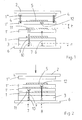
- FIG. 1 shown schematic representation of an inventively designed multi-layer laminating press contains for clarity only three laminator, which are formed by a total of four press plates, which are designed as heating plates 1, 1 ', 1 ", 1"'.
- the uppermost heating plate 1 "' is fastened to a press upper part 2, while the lowermost heating plate 1 sits on a press base 3.
- the press base 3, and thus the lowermost heating plate 1, is fixed in the embodiment shown, while the press upper part 2 can be moved vertically by means of a press mechanism (not shown) in order to be able to move the individual laminator floors together.
- the heating panels 1 are each provided with slotted hangers on the overlying heating panel 1". 'suspended so that they can be moved by lifting against the overlying hot plate 1''.
- a workpiece 5 is arranged by way of example, which when closing the multi-day laminating press under pressure and heat to be laminated.
- two weight compensating elements 7, 8 designed according to the invention as resilient stop elements are fastened. They are in the present FIG. 1
- the travel h of the gas springs 10 corresponds to the maximum stroke of the associated laminator 1 ', 1 ", minus the height of the workpiece 5, which in turn is designated by the reference h the push rods 9 of the weight compensation elements 7 are formed differently long and correspond to the minimum distance between the base 6 and the associated heating plate 1 ', 1 "with closed multi-layer laminating, the gas springs 10 of all weight compensation elements 7, 8 can be provided with the same suspension h and , as far as workpieces 5 are used with identical heights, are controlled with a common control loop, for example, to consider the change from a workpiece thickness to another workpiece thickness.
- the weight compensation elements 7, 8 cooperate with stops 11, 12 which are fastened to the respectively assigned heating plates 1 ', 1 ".
- FIG. 1 is no connection between the weight compensation elements 7, 8 and their associated stops 11, 12, come the push rods 9 of the counterbalance elements 7, 8 when closing the multi-layer laminating press in contact with the stops 11, 12, such as FIG. 2 shows.
- the weight forces of the heating plates 1 ', 1 " are removed via the push rods 9 and the gas pressure springs 10 and introduced into the base 6 of the multi-layer laminating press, so that the workpieces 5 are relieved to the extent , 1 ', 1 ", 1" are arranged so that they are not affected in any way by their waste heat.
- FIG. 2 may be noted at this point that it is only a schematic representation of the relationships according to the invention should clarify.
- a picture like in FIG. 2 shown, in which two laminator 1, 1 'and 1', 1 "are closed, while a third laminator 1", 1 "'is still open, will only set when the weight compensation elements 7, 8 only part of the weight the heating plates 1 ', 1 ", for example, 70 to 90%, intercept.
- the weight compensation elements 7, 8 each remove the weight force to about 100%, a different picture arises: Because the fact that the travel h of the gas springs 10 corresponds to the stroke h of the laminator, and the gas springs 10 during compression increasing proportionally to the traveled travel Create counterforce against the weight of the heating plates 1 ', 1 ", the individual Laminatoretagen close quasi-synchronously
Landscapes
- Engineering & Computer Science (AREA)
- Mechanical Engineering (AREA)
- Physics & Mathematics (AREA)
- Fluid Mechanics (AREA)
- Casting Or Compression Moulding Of Plastics Or The Like (AREA)
- Press Drives And Press Lines (AREA)
- Lining Or Joining Of Plastics Or The Like (AREA)
Abstract
Description
- Die Erfindung betrifft eine Mehretagen-Laminierpresse zum Laminieren von im Wesentlichen plattenförmigen Werkstücken unter Druck- und Wärmeeinwirkung nach dem Oberbegriff des Anspruchs 1.
- Eine Mehretagen-Laminierpresse der vorliegenden Art enthält demnach eine Anzahl von Pressplatten, die jeweils paarweise eine Laminatoretage bilden. Die Laminatoretagen können außer einer untenliegenden und einer obenliegenden Pressplatte weitere Elemente umfassen, wie beispielsweise ein Druckkissen, eine Vakuumkammer und dergleichen. Meist sind die Pressplatten als Heizplatten ausgebildet, um Prozesswärme in die jeweilige Laminatoretage einzubringen. Diese Heizplatten können so ausgebildet sein, dass sie in jeweils zwei Laminatoretagen Wärme abgeben; sie können bedarfsweise jedoch auch nur entweder nach oben oder nach unten Wärme abgeben.
- Die Pressplatten einer Mehretagen-Laminierpresse der vorliegenden Art sind gemeinsam vertikal zusammenfahrbar und können umgekehrt vertikal wieder auseinandergefahren werden, um die Laminierpresse zu schließen und zu öffnen. Zu diesem Zweck sind eine Pressenbasis und/oder ein Pressen-Oberteil vertikal verfahrbar. Dies bedeutet, dass die Pressplatten gegeneinander beweglich am Pressen-Oberteil aufgehängt sind und entweder das Pressen-Oberteil zur feststehenden Pressenbasis hin, oder eine bewegliche Pressenbasis zum dann feststehenden Pressen-Oberteil hin nach unten bzw. nach oben bewegt wird, so dass sich die Laminatoretagen sukzessive schließen. Im Rahmen der vorliegenden Erfindung können alternativ auch sowohl die Pressenbasis als auch das Pressen-Oberteil vertikal bewegbar sein und sich zum Schließen der Laminierpresse zueinander bewegen.
- Ein Problem bei einer solchen Mehretagen-Laminierpresse besteht darin, dass die Pressplatten ein relativ hohes Eigengewicht haben. Wenn nun beispielsweise die Pressenbasis nach oben zum Pressen-Oberteil hin bewegt wird, um die Mehretagen-Laminierpresse zu schließen, legt sich zunächst die über der Pressenbasis liegende Pressplatte auf die Pressenbasis auf, wird mit dieser zusammen weiter nach oben gefahren, wonach sich die nächste Pressplatte auflegt, so dass die Pressenbasis nun mit zwei aufliegenden Pressplatten bis zur dritten Pressplatte gefahren wird, die sich wiederum oben auflegt usw. Der Druck, der in der untersten Laminatoretage, zwischen der Pressenbasis und der ersten Pressplatte herrscht, wird also von Pressplatte zu Pressplatte verstärkt, da die Gewichte aller oberhalb liegenden und aufgefahrenen Pressplatten aufaddiert auf der untersten Laminatoretage lasten. Wenn Werkstücke laminiert werden sollen, die lediglich mit einem begrenzten Druck beaufschlagt werden dürfen, wie beispielsweise Photovoltaik-Module, bestehend im Wesentlichen aus einer Solarzellenschicht mit elektrischen Kontaktierungselementen, einer Trägerschicht und einer aus Glas bestehenden Abdeckung, muss jedoch vermieden werden, dass die Gewichte der über einer bestimmten Laminatoretage liegenden Pressplatten auf dieser Laminatoretage lasten.
- Zur Vermeidung dieses Problems ist in der
US 3,468,243 vorgeschlagen worden, das Schließen der Mehretage-Laminierpresse über eine Hebelmechanik auf die einzelnen Pressplatten zu übersetzen, so dass jede einzelne Pressplatte an einem gemeinsamen, von der Pressenbasis bewegten Hebel hängt und in einem bestimmten Übersetzungsverhältnis indirekt von der Pressenbasis nach oben gegen das Pressen-Oberteil bewegt wird. Hierdurch schießen sich alle Laminatoretagen synchron, und die Gewichtskraft der Pressplatten wird über die Hebelmechanik kompensiert. Allerdings benötigt eine solche Hebelmechanik einen überaus großen Bauraum, und sie muss sehr genau und aufwändig auf die Abmessungen der zu laminierenden Werkstücke justiert werden. - In der
EP-A-0 972 636 ist deshalb vorgeschlagen worden, den Pressplatten anstelle einer aufwändigen Hebelmechanik jeweils Gewichtsausgleichselemente zuzuordnen, welche die im zusammengefahrenen Zustand vom Eigengewicht der jeweiligen Pressplatte erzeugte Gewichtskraft zumindest zum Teil kompensiert. Die Gewichtsausgleichselemente nach diesem Stand der Technik sind als Fluidzylinder ausgebildet, die die einfache Aufhängung jeder Pressplatte an der nächst darüberliegenden Pressplatte ersetzen bzw. ergänzen und jede Pressplatte beim Schließen der Mehretagen-Laminierpresse relativ zur nächsthöheren Platte oder vorzugsweise relativ zu einem feststehenden Pressen-Oberteil so weit anheben, dass deren Gewichtskraft bis zu etwa 90 % kompensiert wird. Um dieses Ziel zu erreichen, werden die Fluidzylinder mit jeweils einer eigenen Regeleinheit angesteuert, was naturgemäß aufwändig ist und wiederum einen nicht zu vernachlässigenden Bauraum in Anspruch nimmt. - Der vorliegenden Erfindung liegt die Aufgabe zugrunde, eine Mehretagen-Laminierpresse der voranstehend beschriebenen Art trotz Beibehalten von Gewichtsausgleichselementen für die Pressplatten zu vereinfachen.
- Gelöst ist diese Aufgabe durch eine Mehretagen-Laminierpresse mit den Merkmalen des Anspruchs 1. Bevorzugte Ausgestaltungen und Weiterbildungen der erfindungsgemäßen Mehretagen-Laminierpesse finden sich in den Ansprüchen 2 bis 10.
- Nach der vorliegenden Erfindung werden die Gewichtsausgleichselemente demnach als federnde Anschlagselemente ausgebildet, die an der Pressenbasis und/oder dem Pressen-Oberteil direkt oder indirekt gegengelagert sind. Da die Gewichtsausgleichselemente als Anschlagselemente ausgebildet sind, erübrigt sich eine separate Regelung. Beim Zufahren einer Laminatoretage wird das Gewicht der jeweils obenliegenden Pressplatte mittels der federnden Eigenschaft des erfindungsgemäßen Anschlagselements durch die zunehmende Federvorspannung zunehmend kompensiert, bis sie beim Auffahren auf das Anschlagselement zu einem Großteil oder sogar ganz kompensiert wird. Zweckmäßigerweise wird die federnde Strecke des als Anschlagselement ausgebildeten Gewichtsausgleichselements allerdings so lang gewählt, dass die entsprechende Pressplatte nie gegen den "harten" Anschlag läuft. Da die erfindungsgemäßen Anschlagselemente an der Pressenbasis und/oder dem Pressen-Oberteil gegengelagert sind, muss die Federstrecke jeweils lediglich dem maximalen Abstand zwischen zwei Pressplatten einer Laminatoretage entsprechen; denn bei vollständig geschlossener Mehretagen-Laminierpresse sind die Abstände zwischen jeder einzelnen Pressplatte und sowohl dem Pressen-Oberteil als auch der Pressenbasis definiert festgelegt und werden in keinem Fall unterschritten.
- Die Gewichtsausgleichselemente können jeweils einen Hydraulikzylinder mit nachgeschaltetem, hydropneumatischem Druckspeicher umfassen, wobei das im hydropneumatischen Druckspeicher enthaltene Luftpolster die federnde Eigenschaft des Anschlagselements realisiert. Der Hydraulikzylinder bildet dann einen sehr leicht regelbaren Anschlag.
- Anstatt eines hydropneumatischen Druckspeichers kann der Hydraulikzylinder auch mit einer aktiven Druckregelung versehen werden, die eine Pumpe und eine Regeleinheit enthält, um die federnde Eigenschaft mit zunehmender Rückstellkraft zu übernehmen. Diese Druckregelung des Hydraulikzylinders wird vorzugsweise abhängig von den Signalen einer Hubbewegungsüberwachung der beteiligten Pressplatten elektronisch geregelt.
- Besonders bevorzugt wird als federndes Element in den erfindungsgemäßen Gewichtausgleichselementen jedoch eine Gasdruckfeder verwendet. Diese ist variabel und sehr einfach einstellbar und kann gegebenenfalls auch geregelt werden, beispielsweise um Gewichtsänderungen in den einzelnen Laminatoretagen durch unterschiedliche Belegung derselben mit Werkstücken zu berücksichtigen.
- Um zu verhindern, dass die Gasdruckfedern von der Abwärme der Laminatoretagen beeinflusst werden, werden diese vorzugsweise im Bereich der (nicht beheizten) Pressenbasis angeordnet. Bei einer Mehretagen-Laminierpresse, bei der die Pressenbasis feststeht und das Pressen-Oberteil zum Öffnen und Schließen vertikal bewegt wird, können die Gasdruckfedern ganz einfach am Boden bzw. an der Basis des Gestells der Mehretagen-Laminierpresse angeordnet werden.
- Weitere Vorteile ergeben sich hierbei, wenn die Gewichtsausgleichselemente im Wesentlichen aus der eben genannten Gasdruckfeder sowie einer daran angebrachten Schubstange und einem an der jeweiligen Pressplatte befestigten, zur Aufnahme der Schubstange vorgesehenen, jedoch nicht an der Schubstange angebrachten Anschlag besteht. Die Schubstange und der an der Pressplatte angebrachte Anschlag berühren sich also erst dann, wenn die Mehretagen-Laminierpresse so weit geschlossen worden ist, dass sich die der Schubstange zugeordnete Pressplatte auf die darunterliegende Pressplatte absenkt und damit die entsprechende Laminatoretage schließt. Der Weg, den diese Pressplatte zum Schließen der Laminatoretage zurücklegen muss, entspricht dann dem Federweg der Gasdruckfeder, so dass die Schubstange unnachgiebig und in ihrer Länge unveränderbar ausgestaltet sein kann. Über die am Anschlag der Pressplatte anliegende bzw. in diesem Anschlag sitzende Schubstange wird die Gewichtskraft der Pressplatte auf die im Bereich der Pressenbasis angeordnete Gasdruckfeder abgetragen und von dieser zumindest teilweise kompensiert. Der Federweg der Gasdruckfeder wird hierbei, wie bereits erwähnt, zweckmäßigerweise so gewählt, dass er länger ist als der maximal mögliche Hub der zugeordneten Laminatoretage, so dass die Pressplatte, deren Gewichtskraft über die Schubstange in die Gasdruckfeder eingeleitet wird, nie gegen einen unnachgiebigen Anschlag läuft.
- Beim Öffnen der Mehretagen-Laminierpresse löst sich die Schubstange vom Anschlag der ihr zugeordneten Pressplatte in dem Moment, in dem die entsprechende Laminatoretage komplett geöffnet ist und die Pressplatte beginnt, die darunterliegende Pressplatte mit nach oben zu nehmen.
- Durch die proportional zum Federweg ansteigende Federkraft der Gasdruckfeder kann sich im Übrigen dann ein quasi-synchrones Schließen aller Laminator-etagen anstatt eines sukzessiven Schließens derselben von unten nach oben ergeben, wenn die Federkraft in etwa gleich der jeweils abgetragenen Gewichtskraft der Pressplatte ist. Dies kann Vorteile bieten, da dann alle zu laminierenden Werkstücke in allen Laminatoretagen gleichbehandelt werden, und nicht etwa die unten liegenden Werkstücke länger in der Mehretagen-Laminierpresse mit Druck beaufschlagt werden, als die oben prozessierten Werkstücke.
- Die erfindungsgemäß ausgebildeten Gewichtsausgleichselemente weisen vorzugsweise einen Federweg auf, der in etwa gleich - zweckmäßigerweise etwas größer als - der Hub der zugeordneten Laminatoretage ist, naturgemäß abzüglich der Dicke des zu laminierenden Werkstücks. Bevorzugt ist es jedoch, wenn der Federweg der Gewichtsausgleichselemente regelbar ist und wahlweise entweder in etwa dem Hub der zugeordneten Laminatoretage oder dem Hub der zugeordneten Laminatoretage abzüglich der Dicke des zu laminierenden Werkstücks entspricht. Die Mehretagen-Laminierpresse kann dann auch problemlos mit nur einer Teilbelegung ihrer Laminatoretagen mit Werkstücken verwendet werden.
- Ein Ausführungsbeispiel der vorliegenden Erfindung wird im Folgenden anhand der beigefügten Zeichnungen näher beschrieben und erläutert. Es zeigen:
- Figur 1
- eine schematische seitliche Ansicht einer erfindungsgemäß ausgestalteten Mehretagen-Laminierpresse mit drei Laminatoretagen, in geöffnetem Zustand;
- Figur 2
- die Ansicht aus
Figur 1 in zum Teil geschlossenem Zustand. - Die in
Figur 1 gezeigte schematische Darstellung einer erfindungsgemäß ausgestalteten Mehretagen-Laminierpresse enthält zur besseren Übersichtlichkeit lediglich drei Laminatoretagen, die von insgesamt vier Pressplatten, die als Heizplatten 1, 1', 1", 1"' ausgeführt sind, gebildet werden. Die oberste Heizplatte 1"' ist an einem Pressen-Oberteil 2 befestigt, während die unterste Heizplatte 1 auf einer Pressenbasis 3 sitzt. Die Pressenbasis 3, und damit die unterste Heizplatte 1, ist im gezeigten Ausführungsbeispiel feststehend ausgebildet, während das Pressen-Oberteil 2 über eine (nicht dargestellte) Pressenmechanik vertikal verfahrbar ist, um die einzelnen Laminatoretagen zusammenfahren zu können. Wie in der obersten Laminatoretage 1", 1"' beispielhaft angedeutet ist, sind die Heizplatten 1" jeweils mit Langloch-Aufhängungen an der darüberliegenden Heizplatte 1"' solcherart aufgehängt, dass sie durch Anheben gegen die darüberliegende Heizplatte 1"' bewegt werden können. In jeder der drei Laminatoretagen ist ein Werkstück 5 beispielhaft angeordnet, welches beim Schließen der Mehretagen-Laminierpresse unter Druck- und Wärmeeinwirkung laminiert werden soll. - Im Bereich der Pressenbasis 3, an einem Sockel 6 der Mehretagen-Laminierpresse, sind zwei erfindungsgemäß als federnde Anschlagselemente ausgebildete Gewichtsausgleichselemente 7, 8 befestigt. Sie sind in der vorliegenden
Figur 1 schematisch dargestellt und bestehen aus jeweils einer Schubstange 9 und einer Gasdruckfeder 10. Der Federweg h der Gasdruckfedern 10 entspricht dem maximalen Hub der zugeordneten Laminatoretage 1', 1", abzüglich der Höhe des Werkstücks 5, der wiederum mit dem Bezugszeichen h bezeichnet ist. Da die Schubstangen 9 der Gewichtsausgleichselemente 7 unterschiedlich lang ausgebildet sind und dem minimalen Abstand zwischen dem Sockel 6 und der zugeordneten Heizplatte 1', 1" bei geschlossener Mehretagen-Laminierpresse entsprechen, können die Gasdruckfedern 10 aller Gewichtsausgleichselemente 7, 8 mit demselben Federweg h versehen sein und, soweit Werkstücke 5 mit identischen Höhen verwendet werden, mit einem gemeinsamen Regelkreis geregelt werden, um beispielsweise den Wechsel von einer Werkstückdicke auf eine andere Werkstückdicke zu berücksichtigen. - Die Gewichtsausgleichselemente 7, 8 wirken mit Anschlägen 11, 12 zusammen, die an den jeweils zugeordneten Heizplatten 1', 1" befestigt sind. Während bei geöffneter Mehretagen-Laminierpresse (
Figur 1 ) keine Verbindung zwischen den Gewichtsausgleichselementen 7, 8 und den ihnen zugeordneten Anschlägen 11, 12 besteht, kommen die Schubstangen 9 der Gewichtsausgleichselemente 7, 8 beim Schließen der Mehretagen-Laminierpresse in Anlage mit den Anschlägen 11, 12, wieFigur 2 zeigt. Hierdurch werden die Gewichtskräfte der Heizplatten 1', 1" über die Schubstangen 9 und die Gasdruckfedern 10 abgetragen und in den Sockel 6 der Mehretagen-Laminierpresse eingeleitet, so dass die Werkstücke 5 insofern entlastet werden. Die Gasdruckfedern 10 sind hierbei vorteilhafterweise von sämtlichen Heizplatten 1, 1', 1", 1"' entfernt angeordnet, so dass sie von deren Abwärme in keiner Weise beeinflusst werden. - Zur
Figur 2 darf an diese Stelle angemerkt werden, dass es sich lediglich um eine schematische Darstellung handelt, die die erfindungsgemäßen Zusammenhänge verdeutlichen soll. Ein Bild wie inFigur 2 dargestellt, bei dem zwei Laminatoretagen 1, 1' und 1', 1" geschlossen sind, während eine dritte Laminatoretage 1 ", 1"' noch geöffnet ist, wird sich nur dann einstellen, wenn die Gewichtsausgleichselemente 7, 8 nur einen Teil der Gewichtskraft der Heizplatten 1', 1", beispielsweise 70 bis 90 %, abfangen. Wenn die Gewichtsausgleichselemente 7, 8 die Gewichtskraft jeweils zu etwa 100 % abtragen, ergibt sich ein anders Bild: Denn dadurch, dass der Federweg h der Gasdruckfedern 10 dem Hub h der Laminatoretagen entspricht, und die Gasdruckfedern 10 beim Einfedern eine proportional zum zurückgelegten Federweg ansteigende Gegenkraft gegen die Gewichtskraft der Heizplatten 1', 1" erzeugen, werden sich die einzelnen Laminatoretagen quasi-synchron schließen
Claims (10)
- Mehretagen-Laminierpresse zum Laminieren von im Wesentlichen plattenförmigen Werkstücken unter Druck- und Wärmeeinwirkung, umfassend eine Anzahl von, jeweils paarweise eine Laminatoretage bildenden, gemeinsam vertikal zusammenfahrbaren Pressplatten (1, 1', 1", 1"'), eine Pressenbasis (3) und ein Pressen-Oberteil (2), wobei die Pressenbasis (3) und/oder das Pressen-Oberteil (2) vertikal verfahrbar sind, um die Pressplatten (1, 1', 1", 1"') zusammenzufahren, sowie Gewichtsausgleichselemente (7, 8), die den Pressplatten (1', 1") zugeordnet sind, um die im zusammengefahrenen Zustand vom Eigengewicht der jeweiligen Pressplatte (1', 1") erzeugte Gewichtskraft zumindest zum Teil zu kompensieren,
dadurch gekennzeichnet,
dass die Gewichtsausgleichselemente (7, 8) als an der Pressenbasis (3) und/oder dem Pressen-Oberteil (2) gegengelagerte, federnde Anschlagselemente ausgebildet sind. - Mehretagen-Laminierpresse nach Anspruch 1,
dadurch gekennzeichnet,
dass die Gewichtsausgleichselemente (7, 8) jeweils eine Gasdruckfeder (10) enthalten. - Mehretagen-Laminierpresse nach Anspruch 2,
dadurch gekennzeichnet,
dass die Gasdruckfedern (10) im Bereich der Pressenbasis (3) angeordnet sind. - Mehretagen-Laminierpresse nach Anspruch 3,
dadurch gekennzeichnet,
dass die Gewichtsausgleichselemente (7, 8) im Wesentlichen aus der Gasdruckfeder (10), einer daran angebrachten Schubstange (9) und einem an der jeweiligen Pressplatte (1') befestigten, zur Aufnahme der Schubstange (9) vorgesehenen, jedoch nicht an der Schubstange (9) befestigten Anschlag (11) bestehen. - Mehretagen-Laminierpresse nach mindestens einem der Ansprüche 2 bis 4,
dadurch gekennzeichnet,
dass die Gasdruckfeder (10) regelbar ausgebildet ist. - Mehretagen-Laminierpresse nach Anspruch 1,
dadurch gekennzeichnet,
dass die Gewichtsausgleichselemente (7, 8) einen Hydraulikzylinder mit nachgeschaltetem hydropneumatischen Druckspeicher enthalten. - Mehretagen-Laminierpresse nach Anspruch 1,
dadurch gekennzeichnet,
dass die Gewichtsausgleichselemente (7, 8) jeweils einen Hydraulikzylinder mit aktiver Druckregelung, umfassend eine Pumpe und eine Regeleinheit, enthalten. - Mehretagen-Laminierpresse nach Anspruch 7,
dadurch gekennzeichnet,
dass die Druckregelung des Hydraulikzylinders abhängig von den Signalen einer Hubbewegungsüberwachung elektronisch geregelt ist. - Mehretagen-Laminierpresse nach mindestens einem der Ansprüche 1 bis 8,
dadurch gekennzeichnet,
dass die Gewichtsausgleichselemente (7, 8) einen Federweg (h) aufweisen, der in etwa dem Hub (h) der zugeordneten Laminatoretage (1', 1") abzüglich der Dicke des zu laminierenden Werkstücks (5) entspricht. - Mehretagen-Laminierpresse nach mindestens einem der Ansprüche 1 bis 8,
dadurch gekennzeichnet,
dass der Federweg (h) der Gewichtsausgleichselemente (7, 8) regelbar ist und wahlweise entweder in etwa dem Hub der zugeordneten Laminatoretage (1', 1") oder dem Hub der zugeordneten Laminatoretage (1', 1") abzüglich der Dicke des zu laminierenden Werkstücks (5) entspricht.
Applications Claiming Priority (1)
| Application Number | Priority Date | Filing Date | Title |
|---|---|---|---|
| DE200820009719 DE202008009719U1 (de) | 2008-07-18 | 2008-07-18 | Mehretagen-Laminierpresse |
Publications (3)
| Publication Number | Publication Date |
|---|---|
| EP2145753A2 true EP2145753A2 (de) | 2010-01-20 |
| EP2145753A3 EP2145753A3 (de) | 2012-12-19 |
| EP2145753B1 EP2145753B1 (de) | 2017-12-06 |
Family
ID=39778006
Family Applications (1)
| Application Number | Title | Priority Date | Filing Date |
|---|---|---|---|
| EP09008180.3A Active EP2145753B1 (de) | 2008-07-18 | 2009-06-23 | Mehretagen-Laminierpresse |
Country Status (3)
| Country | Link |
|---|---|
| EP (1) | EP2145753B1 (de) |
| DE (1) | DE202008009719U1 (de) |
| TR (1) | TR201802381T4 (de) |
Cited By (1)
| Publication number | Priority date | Publication date | Assignee | Title |
|---|---|---|---|---|
| EP3991971A1 (de) | 2020-10-28 | 2022-05-04 | Qinhuangdao Visible Automation Equipment Co. Ltd. | Plattenpressenlaminator und druckaufbringungsverfahren |
Citations (2)
| Publication number | Priority date | Publication date | Assignee | Title |
|---|---|---|---|---|
| US3468243A (en) | 1966-01-03 | 1969-09-23 | Niederrheinische Mas Fab Backe | Device for compensating the weight of the heating plates in multistage presses with simultaneous closing mechanism |
| EP0972636A2 (de) | 1998-07-13 | 2000-01-19 | Robert Bürkle GmbH | Mehretagenpresse für laminierte Plastikkarten |
Family Cites Families (4)
| Publication number | Priority date | Publication date | Assignee | Title |
|---|---|---|---|---|
| DE953384C (de) * | 1955-04-05 | 1956-11-29 | Becker & Van Huellen | Etagenschliesseinrichtung an Etagenpressen mit ortsfestem Widerlager |
| IT1002460B (it) * | 1973-12-31 | 1976-05-20 | Simpres Soc Italiana Materiali | Pressa a piani multipli per la for matura di pannelli e simili |
| JPH07108476B2 (ja) * | 1992-12-25 | 1995-11-22 | 北川精機株式会社 | 多段プレス装置及びその連続プレス作動方法 |
| FR2802463B1 (fr) * | 1999-11-05 | 2002-01-18 | Valeo | Presse a plateaux multiples |
-
2008
- 2008-07-18 DE DE200820009719 patent/DE202008009719U1/de not_active Expired - Lifetime
-
2009
- 2009-06-23 EP EP09008180.3A patent/EP2145753B1/de active Active
- 2009-06-23 TR TR2018/02381T patent/TR201802381T4/tr unknown
Patent Citations (2)
| Publication number | Priority date | Publication date | Assignee | Title |
|---|---|---|---|---|
| US3468243A (en) | 1966-01-03 | 1969-09-23 | Niederrheinische Mas Fab Backe | Device for compensating the weight of the heating plates in multistage presses with simultaneous closing mechanism |
| EP0972636A2 (de) | 1998-07-13 | 2000-01-19 | Robert Bürkle GmbH | Mehretagenpresse für laminierte Plastikkarten |
Cited By (2)
| Publication number | Priority date | Publication date | Assignee | Title |
|---|---|---|---|---|
| EP3991971A1 (de) | 2020-10-28 | 2022-05-04 | Qinhuangdao Visible Automation Equipment Co. Ltd. | Plattenpressenlaminator und druckaufbringungsverfahren |
| EP3991971B1 (de) * | 2020-10-28 | 2024-11-13 | Qinhuangdao Visual Automation Equipment Co. Ltd. | Plattenpressenlaminator und druckaufbringungsverfahren |
Also Published As
| Publication number | Publication date |
|---|---|
| EP2145753A3 (de) | 2012-12-19 |
| DE202008009719U1 (de) | 2008-09-25 |
| TR201802381T4 (tr) | 2018-03-21 |
| EP2145753B1 (de) | 2017-12-06 |
Similar Documents
| Publication | Publication Date | Title |
|---|---|---|
| EP3707330B1 (de) | Klappenbeschlag für ein möbel, seitenwand eines möbelkorpus und möbel mit einer seitenwand | |
| EP3700764B1 (de) | Feder-dämpfersystem mit variabler federrate | |
| WO1986006053A1 (fr) | Dispositif de levage | |
| EP2017020A2 (de) | Verfahren und Biegemaschine zur Kompensation der Durchbiegung von Teilen dieser Biegemaschine | |
| EP2243977A2 (de) | Luftfeder-Dämpfer | |
| EP1507980A1 (de) | Hydraulische steuerung in einem hydraulischen system, insbesondere für den betrieb einer schrottschere | |
| DE3939124A1 (de) | Vielwalzengeruest mit hydraulischer anstellung | |
| EP2145753B1 (de) | Mehretagen-Laminierpresse | |
| DE102010003368A1 (de) | Verfahren zur Herstellung von Werkstoffplatten in einer kontinuierlich arbeitende Presse und eine kontinuierlich arbeitende Presse | |
| DE102018009934A1 (de) | Bewegungs-Liege | |
| DE102009015893A1 (de) | Verfahren zur Herstellung von Werkstoffplatten in einer kontinuierlich arbeitende Presse und eine kontinuierlich arbeitende Presse | |
| DE2845055A1 (de) | Verfahren zum schnellen trennen der walzen eines kalanders und vorrichtung zu dessen durchfuehrung | |
| DE2856000A1 (de) | Anlage zur verguetung von blechen | |
| EP1227904B1 (de) | Tiefziehpresse und verfahren zum tiefziehen von blechwerkstücken | |
| DE19520109C1 (de) | Kalander für die Voll- und Leichtsatinage | |
| DE4428768A1 (de) | Presse mit zumindest zwei übereinanderliegenden Druckräumen | |
| EP0949049B1 (de) | Mehrkammerpresse | |
| DE10059635A1 (de) | Kniehebelpresse | |
| DE3212233A1 (de) | Zweioeffnungspresse zum herstellen von span- und daemmplatten oder dgl. | |
| AT507132A1 (de) | Laminierpresse mit prozessplatte | |
| EP1927557B1 (de) | Lagervorrichtung | |
| EP1772417B1 (de) | Hubtisch | |
| DE2755690A1 (de) | Vorrichtung fuer die lagerung, handhabung und den transport von zerbrechlichem material in tafelform | |
| DE19643396A1 (de) | Hydraulische Steuereinrichtung | |
| DE3514776C1 (de) | Vorrichtung zum Überbrücken von Dehnfugen in Gehwegen und Fahrbahnen |
Legal Events
| Date | Code | Title | Description |
|---|---|---|---|
| PUAI | Public reference made under article 153(3) epc to a published international application that has entered the european phase |
Free format text: ORIGINAL CODE: 0009012 |
|
| AK | Designated contracting states |
Kind code of ref document: A2 Designated state(s): AT BE BG CH CY CZ DE DK EE ES FI FR GB GR HR HU IE IS IT LI LT LU LV MC MK MT NL NO PL PT RO SE SI SK TR |
|
| AX | Request for extension of the european patent |
Extension state: AL BA RS |
|
| PUAL | Search report despatched |
Free format text: ORIGINAL CODE: 0009013 |
|
| AK | Designated contracting states |
Kind code of ref document: A3 Designated state(s): AT BE BG CH CY CZ DE DK EE ES FI FR GB GR HR HU IE IS IT LI LT LU LV MC MK MT NL NO PL PT RO SE SI SK TR |
|
| AX | Request for extension of the european patent |
Extension state: AL BA RS |
|
| RIC1 | Information provided on ipc code assigned before grant |
Ipc: B32B 37/10 20060101ALI20121115BHEP Ipc: B30B 7/02 20060101AFI20121115BHEP Ipc: B30B 15/00 20060101ALI20121115BHEP Ipc: B32B 37/00 20060101ALI20121115BHEP |
|
| 17P | Request for examination filed |
Effective date: 20130419 |
|
| 17Q | First examination report despatched |
Effective date: 20150519 |
|
| GRAP | Despatch of communication of intention to grant a patent |
Free format text: ORIGINAL CODE: EPIDOSNIGR1 |
|
| STAA | Information on the status of an ep patent application or granted ep patent |
Free format text: STATUS: GRANT OF PATENT IS INTENDED |
|
| INTG | Intention to grant announced |
Effective date: 20170720 |
|
| GRAS | Grant fee paid |
Free format text: ORIGINAL CODE: EPIDOSNIGR3 |
|
| GRAA | (expected) grant |
Free format text: ORIGINAL CODE: 0009210 |
|
| STAA | Information on the status of an ep patent application or granted ep patent |
Free format text: STATUS: THE PATENT HAS BEEN GRANTED |
|
| AK | Designated contracting states |
Kind code of ref document: B1 Designated state(s): AT BE BG CH CY CZ DE DK EE ES FI FR GB GR HR HU IE IS IT LI LT LU LV MC MK MT NL NO PL PT RO SE SI SK TR |
|
| REG | Reference to a national code |
Ref country code: GB Ref legal event code: FG4D Free format text: NOT ENGLISH |
|
| REG | Reference to a national code |
Ref country code: AT Ref legal event code: REF Ref document number: 952014 Country of ref document: AT Kind code of ref document: T Effective date: 20171215 Ref country code: CH Ref legal event code: EP |
|
| REG | Reference to a national code |
Ref country code: IE Ref legal event code: FG4D Free format text: LANGUAGE OF EP DOCUMENT: GERMAN |
|
| REG | Reference to a national code |
Ref country code: DE Ref legal event code: R096 Ref document number: 502009014574 Country of ref document: DE |
|
| REG | Reference to a national code |
Ref country code: NL Ref legal event code: MP Effective date: 20171206 |
|
| REG | Reference to a national code |
Ref country code: LT Ref legal event code: MG4D |
|
| PG25 | Lapsed in a contracting state [announced via postgrant information from national office to epo] |
Ref country code: FI Free format text: LAPSE BECAUSE OF FAILURE TO SUBMIT A TRANSLATION OF THE DESCRIPTION OR TO PAY THE FEE WITHIN THE PRESCRIBED TIME-LIMIT Effective date: 20171206 Ref country code: ES Free format text: LAPSE BECAUSE OF FAILURE TO SUBMIT A TRANSLATION OF THE DESCRIPTION OR TO PAY THE FEE WITHIN THE PRESCRIBED TIME-LIMIT Effective date: 20171206 Ref country code: NO Free format text: LAPSE BECAUSE OF FAILURE TO SUBMIT A TRANSLATION OF THE DESCRIPTION OR TO PAY THE FEE WITHIN THE PRESCRIBED TIME-LIMIT Effective date: 20180306 Ref country code: SE Free format text: LAPSE BECAUSE OF FAILURE TO SUBMIT A TRANSLATION OF THE DESCRIPTION OR TO PAY THE FEE WITHIN THE PRESCRIBED TIME-LIMIT Effective date: 20171206 Ref country code: LT Free format text: LAPSE BECAUSE OF FAILURE TO SUBMIT A TRANSLATION OF THE DESCRIPTION OR TO PAY THE FEE WITHIN THE PRESCRIBED TIME-LIMIT Effective date: 20171206 |
|
| PG25 | Lapsed in a contracting state [announced via postgrant information from national office to epo] |
Ref country code: LV Free format text: LAPSE BECAUSE OF FAILURE TO SUBMIT A TRANSLATION OF THE DESCRIPTION OR TO PAY THE FEE WITHIN THE PRESCRIBED TIME-LIMIT Effective date: 20171206 Ref country code: HR Free format text: LAPSE BECAUSE OF FAILURE TO SUBMIT A TRANSLATION OF THE DESCRIPTION OR TO PAY THE FEE WITHIN THE PRESCRIBED TIME-LIMIT Effective date: 20171206 Ref country code: BG Free format text: LAPSE BECAUSE OF FAILURE TO SUBMIT A TRANSLATION OF THE DESCRIPTION OR TO PAY THE FEE WITHIN THE PRESCRIBED TIME-LIMIT Effective date: 20180306 Ref country code: GR Free format text: LAPSE BECAUSE OF FAILURE TO SUBMIT A TRANSLATION OF THE DESCRIPTION OR TO PAY THE FEE WITHIN THE PRESCRIBED TIME-LIMIT Effective date: 20180307 |
|
| REG | Reference to a national code |
Ref country code: FR Ref legal event code: PLFP Year of fee payment: 10 |
|
| PG25 | Lapsed in a contracting state [announced via postgrant information from national office to epo] |
Ref country code: NL Free format text: LAPSE BECAUSE OF FAILURE TO SUBMIT A TRANSLATION OF THE DESCRIPTION OR TO PAY THE FEE WITHIN THE PRESCRIBED TIME-LIMIT Effective date: 20171206 |
|
| PG25 | Lapsed in a contracting state [announced via postgrant information from national office to epo] |
Ref country code: EE Free format text: LAPSE BECAUSE OF FAILURE TO SUBMIT A TRANSLATION OF THE DESCRIPTION OR TO PAY THE FEE WITHIN THE PRESCRIBED TIME-LIMIT Effective date: 20171206 Ref country code: CZ Free format text: LAPSE BECAUSE OF FAILURE TO SUBMIT A TRANSLATION OF THE DESCRIPTION OR TO PAY THE FEE WITHIN THE PRESCRIBED TIME-LIMIT Effective date: 20171206 Ref country code: SK Free format text: LAPSE BECAUSE OF FAILURE TO SUBMIT A TRANSLATION OF THE DESCRIPTION OR TO PAY THE FEE WITHIN THE PRESCRIBED TIME-LIMIT Effective date: 20171206 |
|
| PG25 | Lapsed in a contracting state [announced via postgrant information from national office to epo] |
Ref country code: PL Free format text: LAPSE BECAUSE OF FAILURE TO SUBMIT A TRANSLATION OF THE DESCRIPTION OR TO PAY THE FEE WITHIN THE PRESCRIBED TIME-LIMIT Effective date: 20171206 Ref country code: RO Free format text: LAPSE BECAUSE OF FAILURE TO SUBMIT A TRANSLATION OF THE DESCRIPTION OR TO PAY THE FEE WITHIN THE PRESCRIBED TIME-LIMIT Effective date: 20171206 |
|
| REG | Reference to a national code |
Ref country code: DE Ref legal event code: R097 Ref document number: 502009014574 Country of ref document: DE |
|
| PG25 | Lapsed in a contracting state [announced via postgrant information from national office to epo] |
Ref country code: MT Free format text: LAPSE BECAUSE OF FAILURE TO SUBMIT A TRANSLATION OF THE DESCRIPTION OR TO PAY THE FEE WITHIN THE PRESCRIBED TIME-LIMIT Effective date: 20171206 |
|
| PLBE | No opposition filed within time limit |
Free format text: ORIGINAL CODE: 0009261 |
|
| STAA | Information on the status of an ep patent application or granted ep patent |
Free format text: STATUS: NO OPPOSITION FILED WITHIN TIME LIMIT |
|
| 26N | No opposition filed |
Effective date: 20180907 |
|
| PG25 | Lapsed in a contracting state [announced via postgrant information from national office to epo] |
Ref country code: DK Free format text: LAPSE BECAUSE OF FAILURE TO SUBMIT A TRANSLATION OF THE DESCRIPTION OR TO PAY THE FEE WITHIN THE PRESCRIBED TIME-LIMIT Effective date: 20171206 Ref country code: SI Free format text: LAPSE BECAUSE OF FAILURE TO SUBMIT A TRANSLATION OF THE DESCRIPTION OR TO PAY THE FEE WITHIN THE PRESCRIBED TIME-LIMIT Effective date: 20171206 |
|
| REG | Reference to a national code |
Ref country code: BE Ref legal event code: MM Effective date: 20180630 |
|
| REG | Reference to a national code |
Ref country code: IE Ref legal event code: MM4A |
|
| PG25 | Lapsed in a contracting state [announced via postgrant information from national office to epo] |
Ref country code: MC Free format text: LAPSE BECAUSE OF FAILURE TO SUBMIT A TRANSLATION OF THE DESCRIPTION OR TO PAY THE FEE WITHIN THE PRESCRIBED TIME-LIMIT Effective date: 20171206 Ref country code: LU Free format text: LAPSE BECAUSE OF NON-PAYMENT OF DUE FEES Effective date: 20180623 |
|
| PG25 | Lapsed in a contracting state [announced via postgrant information from national office to epo] |
Ref country code: IE Free format text: LAPSE BECAUSE OF NON-PAYMENT OF DUE FEES Effective date: 20180623 |
|
| PG25 | Lapsed in a contracting state [announced via postgrant information from national office to epo] |
Ref country code: BE Free format text: LAPSE BECAUSE OF NON-PAYMENT OF DUE FEES Effective date: 20180630 |
|
| REG | Reference to a national code |
Ref country code: AT Ref legal event code: MM01 Ref document number: 952014 Country of ref document: AT Kind code of ref document: T Effective date: 20180623 |
|
| PG25 | Lapsed in a contracting state [announced via postgrant information from national office to epo] |
Ref country code: AT Free format text: LAPSE BECAUSE OF NON-PAYMENT OF DUE FEES Effective date: 20180623 |
|
| PG25 | Lapsed in a contracting state [announced via postgrant information from national office to epo] |
Ref country code: HU Free format text: LAPSE BECAUSE OF FAILURE TO SUBMIT A TRANSLATION OF THE DESCRIPTION OR TO PAY THE FEE WITHIN THE PRESCRIBED TIME-LIMIT; INVALID AB INITIO Effective date: 20090623 Ref country code: PT Free format text: LAPSE BECAUSE OF FAILURE TO SUBMIT A TRANSLATION OF THE DESCRIPTION OR TO PAY THE FEE WITHIN THE PRESCRIBED TIME-LIMIT Effective date: 20171206 |
|
| PG25 | Lapsed in a contracting state [announced via postgrant information from national office to epo] |
Ref country code: MK Free format text: LAPSE BECAUSE OF NON-PAYMENT OF DUE FEES Effective date: 20171206 Ref country code: CY Free format text: LAPSE BECAUSE OF FAILURE TO SUBMIT A TRANSLATION OF THE DESCRIPTION OR TO PAY THE FEE WITHIN THE PRESCRIBED TIME-LIMIT Effective date: 20171206 |
|
| PG25 | Lapsed in a contracting state [announced via postgrant information from national office to epo] |
Ref country code: IS Free format text: LAPSE BECAUSE OF FAILURE TO SUBMIT A TRANSLATION OF THE DESCRIPTION OR TO PAY THE FEE WITHIN THE PRESCRIBED TIME-LIMIT Effective date: 20180406 |
|
| P01 | Opt-out of the competence of the unified patent court (upc) registered |
Effective date: 20230509 |
|
| PGFP | Annual fee paid to national office [announced via postgrant information from national office to epo] |
Ref country code: DE Payment date: 20250423 Year of fee payment: 17 |
|
| PGFP | Annual fee paid to national office [announced via postgrant information from national office to epo] |
Ref country code: GB Payment date: 20250620 Year of fee payment: 17 |
|
| PGFP | Annual fee paid to national office [announced via postgrant information from national office to epo] |
Ref country code: FR Payment date: 20250626 Year of fee payment: 17 |
|
| PGFP | Annual fee paid to national office [announced via postgrant information from national office to epo] |
Ref country code: TR Payment date: 20250619 Year of fee payment: 17 |
|
| PGFP | Annual fee paid to national office [announced via postgrant information from national office to epo] |
Ref country code: IT Payment date: 20250630 Year of fee payment: 17 |
|
| PGFP | Annual fee paid to national office [announced via postgrant information from national office to epo] |
Ref country code: CH Payment date: 20250701 Year of fee payment: 17 |