EP2145833B1 - Antiextraktionsrückhaltevorrichtung für ein in einen Aufnahmekörper eingeführtes Element - Google Patents
Antiextraktionsrückhaltevorrichtung für ein in einen Aufnahmekörper eingeführtes Element Download PDFInfo
- Publication number
- EP2145833B1 EP2145833B1 EP09165490.5A EP09165490A EP2145833B1 EP 2145833 B1 EP2145833 B1 EP 2145833B1 EP 09165490 A EP09165490 A EP 09165490A EP 2145833 B1 EP2145833 B1 EP 2145833B1
- Authority
- EP
- European Patent Office
- Prior art keywords
- receiving body
- formation
- retaining device
- retaining
- prongs
- Prior art date
- Legal status (The legal status is an assumption and is not a legal conclusion. Google has not performed a legal analysis and makes no representation as to the accuracy of the status listed.)
- Not-in-force
Links
- 238000000605 extraction Methods 0.000 title claims description 8
- 230000015572 biosynthetic process Effects 0.000 claims description 18
- 230000002093 peripheral effect Effects 0.000 description 1
Images


Classifications
-
- B—PERFORMING OPERATIONS; TRANSPORTING
- B65—CONVEYING; PACKING; STORING; HANDLING THIN OR FILAMENTARY MATERIAL
- B65D—CONTAINERS FOR STORAGE OR TRANSPORT OF ARTICLES OR MATERIALS, e.g. BAGS, BARRELS, BOTTLES, BOXES, CANS, CARTONS, CRATES, DRUMS, JARS, TANKS, HOPPERS, FORWARDING CONTAINERS; ACCESSORIES, CLOSURES, OR FITTINGS THEREFOR; PACKAGING ELEMENTS; PACKAGES
- B65D55/00—Accessories for container closures not otherwise provided for
- B65D55/02—Locking devices; Means for discouraging or indicating unauthorised opening or removal of closure
- B65D55/06—Deformable or tearable wires, strings or strips; Use of seals
- B65D55/08—Annular elements encircling container necks
- B65D55/0872—Destructible rigid elements snapping into annular grooves in closure for maintaining closure on container
-
- F—MECHANICAL ENGINEERING; LIGHTING; HEATING; WEAPONS; BLASTING
- F16—ENGINEERING ELEMENTS AND UNITS; GENERAL MEASURES FOR PRODUCING AND MAINTAINING EFFECTIVE FUNCTIONING OF MACHINES OR INSTALLATIONS; THERMAL INSULATION IN GENERAL
- F16B—DEVICES FOR FASTENING OR SECURING CONSTRUCTIONAL ELEMENTS OR MACHINE PARTS TOGETHER, e.g. NAILS, BOLTS, CIRCLIPS, CLAMPS, CLIPS OR WEDGES; JOINTS OR JOINTING
- F16B21/00—Means for preventing relative axial movement of a pin, spigot, shaft or the like and a member surrounding it; Stud-and-socket releasable fastenings
- F16B21/10—Means for preventing relative axial movement of a pin, spigot, shaft or the like and a member surrounding it; Stud-and-socket releasable fastenings by separate parts
- F16B21/16—Means for preventing relative axial movement of a pin, spigot, shaft or the like and a member surrounding it; Stud-and-socket releasable fastenings by separate parts with grooves or notches in the pin or shaft
Definitions
- the present invention relates to a retaining device.
- the invention relates to a retaining device of the kind defined in the preamble of claim 1.
- One object of the present invention is to propose an improved retaining device.
- a retaining device comprises a flat element 1 which, in the example of embodiment shown, has a general C or U shaped configuration.
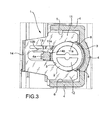
- the flat retaining element 1 is intended to prevent extraction of a member 2, such as a closing stopper, inserted axially inside a front seat 3 ( Figure 3 ) of a receiving body 4.
- the receiving body 4 has, formed therein, a pair of transverse passages 5 and 6, i.e. top passage and bottom passage, respectively, which are vertically aligned with each other. These passages communicate with the seat 3, as can be seen more clearly in Figure 3 , and are separated from each other, in the inlet zone, by a longitudinal cross-piece 4a of the receiving body 4 ( Figures 2 and 3 ).
- the flat retaining element 1 in the example of embodiment shown forms two main arms or prongs 11 and 12 which are intended to embrace, on opposite sides, the member or stopper 2 inserted inside the seat 3 of the receiving body, as can be seen in Figure 3 .
- the arms or prongs 11 and 12 have respective inner profiles which form respective tips or teeth 11a, 12a ( Figures 1 and 3 ), the distance between which is slightly smaller than the maximum diametral dimension of the portion of the member or stopper 2 with which they are intended to engage.
- these prongs 11 and 12 engage, firstly by means of interference, with the corresponding portion of the member or stopper 2 and are elastically splayed until the respective tip-like portions 11a and 12a pass beyond the zone of the member of stopper 2 with the maximum diametral dimension.
- the flat element 1 forms a resilient longitudinal lug 13 terminating in a hook-like formation 13a.
- the latter is able to snap-engage with an associated retaining formation 4b of the receiving body 4.
- the retaining member 4b consists of a step-like formation of the cross-piece 4a of the receiving body 4 ( Figure 3 ).
- the portion of the lug 13 which remains operationally outside the receiving body 4 forms an integral flange 13b which is folded at an angle of about 90° and is intended to facilitate deflection of this lug 13, in an upwards direction when viewing Figures 2 and 3 , when it is required to disengage the hook-like formation 13a from the associated retaining formation 4b, in order to remove the flat retaining element 1 from the receiving body 4, so as to allow subsequent extraction of the member or stopper 2 from the corresponding seat.
- the end of the flat retaining element 1 opposite to that of the prongs 11 and 12 is folded, for example at an angle of about 90°, about a vertical axis, so as to define a shaped gripping flange 14 which is designed to facilitate extraction of the flat element 1 from the passages 5 and 6 of the receiving body 4.
- the portion of the member or stopper 2 which is received inside the seat 3 of the receiving body has at least one transverse engaging formation which, in the embodiment shown, consists of a peripheral collar indicated by 8 in Figure 3 .
- the prongs 11 and 12 of the flat retaining element 1 are engaged between this engaging formation 8 of the member or stopper 2 and the inlet opening of the seat 3 so that extraction of this member or stopper 2 from the seat 3 is prevented.
Landscapes
- Engineering & Computer Science (AREA)
- General Engineering & Computer Science (AREA)
- Mechanical Engineering (AREA)
- Quick-Acting Or Multi-Walled Pipe Joints (AREA)
- Clamps And Clips (AREA)
- Hooks, Suction Cups, And Attachment By Adhesive Means (AREA)
Claims (4)
- Rückhalteeinheit, aufweisend einen Aufnahmekörper (4) und ein Teil (2), das axial in einen vorderen Sitz (3) des Aufnahmekörpers (4) eingesetzt ist, welches Teil (2) zumindest eine transversale Eingriffanordnung (8) aufweist; welche Rückhalteeinheit auch ein flaches Element (1) aufweist, welches zwei Hauptarme bzw. -gabeln (11, 12) bildet, die für ein Zusammenwirken mit der Eingriffanordnung (8) des Teils (2) ausgelegt sind; welches flache Element (1) mit einer verrastbaren, hakenartigen Anordnung (13, 13a) vorgesehen ist;
welche Rückhalteeinheit ferner ein Paar transversaler Verbindungsgänge (5, 6) aufweist, die in Verbindung mit dem in dem Aufnahmekörper (4) gebildeten vorderen Sitz (3) stehen;
welche Hauptarme bzw. -gabeln (11, 12) des flachen Elements (1) dazu ausgelegt sind, in die Verbindungsgänge (5, 6) des Aufnahmekörpers (4) eingebracht zu werden, um einer Entnahme des Teils (2) aus dem Sitz (3) des Aufnahmekörpers (4) vorzubeugen;
welche Rückhalteeinheit dadurch gekennzeichnet ist, dass sie eine zugeordnete Rückhalteanordnung (4a, 4b) aufweist, die in dem Aufnahmekörper (4) in einem Einlassbereich des Paars transversaler Verbindungsgänge (5, 6) vorgesehen ist;
welche transversale Eingriffsanordnung (8) in einem Abschnitt des innerhalb des Sitzes (3) aufgenommenen Teils (2) vorgesehen ist;
welche hakenartige Anordnung (13, 13a) so angeordnet ist, dass sie mit der zugeordneten Rückhalteanordnung (4a, 4b) des Aufnahmekörpers (4) verrastet, um einem Herausnehmen des flachen Elements (1) aus den transversalen Verbindungsgängen (5, 6) des Aufnahmekörpers (4) vorzubeugen. - Rückhalteeinheit nach Anspruch 1, bei welcher die Hauptarme bzw. -gabeln (11, 12) dazu ausgelegt sind, einen Abschnitt des Teils (2) an entgegengesetzten Seiten zu umgreifen, und die hakenartige Anordnung (13a) an einem Vorsprung (13) des flachen Elements (1) zwischen den Hauptarmen bzw. -gabeln (11, 12) ausgebildet ist.
- Rückhalteeinheit nach Anspruch 1 oder 2, bei welcher die hakenartige Anordnung (13, 13a) ein ihr zugeordnetes Betätigungselement (13b) aufweist, das dazu ausgelegt ist, ein Lösen der hakenartigen Anordnung (13, 13a) von der zugehörigen Rückhalteanordnung (4, 4b) des Aufnahmekörpers (4) zu erleichtern.
- Rückhalteeinheit nach einem der vorstehenden Ansprüche, bei welcher ein Endabschnitt des flachen Rückhalteelements (1), welcher jenem mit den Hauptarmen bzw. -gabeln (11, 12) entgegengesetzt liegt, derart gebogen ist, dass es einen Greifvorsprung (14) bildet, der dazu ausgelegt ist, ein Herausnehmen des flachen Rückhalteelements (1) aus den transversalen Verbindungsgängen (5, 6) des Aufnahmekörpers (4) zu erleichtern.
Priority Applications (1)
| Application Number | Priority Date | Filing Date | Title |
|---|---|---|---|
| PL09165490T PL2145833T3 (pl) | 2008-07-15 | 2009-07-15 | Urządzenie ustalające, przeciwdziałające wyciąganiu, dla elementu wprowadzonego do środka korpusu odbierającego |
Applications Claiming Priority (1)
| Application Number | Priority Date | Filing Date | Title |
|---|---|---|---|
| IT000100U ITTO20080100U1 (it) | 2008-07-15 | 2008-07-15 | Dispositivo di ritegno anti-estrazione per un organo inserito in un corpo ricevitore |
Publications (2)
| Publication Number | Publication Date |
|---|---|
| EP2145833A1 EP2145833A1 (de) | 2010-01-20 |
| EP2145833B1 true EP2145833B1 (de) | 2015-11-25 |
Family
ID=41320252
Family Applications (1)
| Application Number | Title | Priority Date | Filing Date |
|---|---|---|---|
| EP09165490.5A Not-in-force EP2145833B1 (de) | 2008-07-15 | 2009-07-15 | Antiextraktionsrückhaltevorrichtung für ein in einen Aufnahmekörper eingeführtes Element |
Country Status (4)
| Country | Link |
|---|---|
| EP (1) | EP2145833B1 (de) |
| ES (1) | ES2562796T3 (de) |
| IT (1) | ITTO20080100U1 (de) |
| PL (1) | PL2145833T3 (de) |
Families Citing this family (1)
| Publication number | Priority date | Publication date | Assignee | Title |
|---|---|---|---|---|
| CN104229343B (zh) * | 2014-08-11 | 2016-09-07 | 上海鸿研物流技术有限公司 | 用于中型散装容器的排放口固定夹 |
Citations (2)
| Publication number | Priority date | Publication date | Assignee | Title |
|---|---|---|---|---|
| DE2657316A1 (de) * | 1975-12-18 | 1977-07-14 | Legris France Sa | Ventil mit spindel zur drehbedienung |
| US4735534A (en) * | 1987-01-12 | 1988-04-05 | Eaton Corporation | Fastener assembly for cylindrical opening |
Family Cites Families (2)
| Publication number | Priority date | Publication date | Assignee | Title |
|---|---|---|---|---|
| DE3241464A1 (de) * | 1982-11-10 | 1984-05-10 | Hans-Hellmut Dipl.-Ing. 2061 Sülfeld Ernst | Sicherungsclip |
| JP4506737B2 (ja) * | 2006-09-08 | 2010-07-21 | トヨタ自動車株式会社 | 摩擦係合装置の支持構造および変速機 |
-
2008
- 2008-07-15 IT IT000100U patent/ITTO20080100U1/it unknown
-
2009
- 2009-07-15 EP EP09165490.5A patent/EP2145833B1/de not_active Not-in-force
- 2009-07-15 ES ES09165490.5T patent/ES2562796T3/es active Active
- 2009-07-15 PL PL09165490T patent/PL2145833T3/pl unknown
Patent Citations (2)
| Publication number | Priority date | Publication date | Assignee | Title |
|---|---|---|---|---|
| DE2657316A1 (de) * | 1975-12-18 | 1977-07-14 | Legris France Sa | Ventil mit spindel zur drehbedienung |
| US4735534A (en) * | 1987-01-12 | 1988-04-05 | Eaton Corporation | Fastener assembly for cylindrical opening |
Also Published As
| Publication number | Publication date |
|---|---|
| PL2145833T3 (pl) | 2016-06-30 |
| EP2145833A1 (de) | 2010-01-20 |
| ITTO20080100U1 (it) | 2010-01-16 |
| ES2562796T3 (es) | 2016-03-08 |
Similar Documents
| Publication | Publication Date | Title |
|---|---|---|
| US8113856B2 (en) | Block-out cover and removal tool | |
| US9446722B2 (en) | Elastic averaging alignment member | |
| EP2578078B1 (de) | Verbinder | |
| EP2743557B1 (de) | Selbstschließender, formschlüssiger Clip | |
| US10436366B2 (en) | Plug-in connector assembly for the connection of lines | |
| CN102317636B (zh) | 具有固定夹的装配件 | |
| EP2001348B1 (de) | Teleskopverlängerung für ein elektrisches hausgerät | |
| US20120091290A1 (en) | Lock structure for wire harness protector | |
| CN102832502B (zh) | 插塞连接器和用于插塞连接器的板 | |
| US9840177B2 (en) | Assist grip | |
| US8485706B2 (en) | Securing device for connecting reflector to adjustment unit of vehicle headlight | |
| WO2012163349A3 (de) | Gerüstbauteil mit wenigstens einem anschlusskopf und verfahren zur befestigung eines wenigstens einen anschlusskopf aufweisenden gerüstbauteils an einem vertikalen gerüstelement | |
| CA2584061A1 (en) | Locking element for a quick connector | |
| JP5909283B2 (ja) | クロスランナコネクタ、および吊り天井格子 | |
| KR20150067075A (ko) | 케이블용 고정 장치 | |
| US20140103672A1 (en) | Fitting part for attachment to a cooking or roasting vessel | |
| JP2014530969A5 (de) | ||
| EP3072756B1 (de) | Verbindungselement zur verbindung von scheibenwischerblättern mit deren betätigungsarmen | |
| WO2008092070A2 (en) | Retained tension multiple ball lock cable tie | |
| US20180119433A1 (en) | Bracket and scaffolding comprising a bracket of this type | |
| EP2276129A1 (de) | Eingreifbares streckglied für kabelladen | |
| EP2145833A1 (de) | Antiextraktionsrückhaltevorrichtung für ein in einen Aufnahmekörper eingeführtes Element | |
| US9964138B2 (en) | Carabiner with wire level for climbing | |
| WO2009090002A1 (en) | Shockproof quick-action closure for an end fitting | |
| GB2137300A (en) | Axial thrust locking clamp |
Legal Events
| Date | Code | Title | Description |
|---|---|---|---|
| PUAI | Public reference made under article 153(3) epc to a published international application that has entered the european phase |
Free format text: ORIGINAL CODE: 0009012 |
|
| AK | Designated contracting states |
Kind code of ref document: A1 Designated state(s): AT BE BG CH CY CZ DE DK EE ES FI FR GB GR HR HU IE IS IT LI LT LU LV MC MK MT NL NO PL PT RO SE SI SK SM TR |
|
| AX | Request for extension of the european patent |
Extension state: AL BA RS |
|
| 17P | Request for examination filed |
Effective date: 20100716 |
|
| 17Q | First examination report despatched |
Effective date: 20100810 |
|
| GRAP | Despatch of communication of intention to grant a patent |
Free format text: ORIGINAL CODE: EPIDOSNIGR1 |
|
| INTG | Intention to grant announced |
Effective date: 20150603 |
|
| GRAS | Grant fee paid |
Free format text: ORIGINAL CODE: EPIDOSNIGR3 |
|
| GRAA | (expected) grant |
Free format text: ORIGINAL CODE: 0009210 |
|
| AK | Designated contracting states |
Kind code of ref document: B1 Designated state(s): AT BE BG CH CY CZ DE DK EE ES FI FR GB GR HR HU IE IS IT LI LT LU LV MC MK MT NL NO PL PT RO SE SI SK SM TR |
|
| REG | Reference to a national code |
Ref country code: GB Ref legal event code: FG4D |
|
| REG | Reference to a national code |
Ref country code: CH Ref legal event code: EP |
|
| REG | Reference to a national code |
Ref country code: AT Ref legal event code: REF Ref document number: 762461 Country of ref document: AT Kind code of ref document: T Effective date: 20151215 |
|
| REG | Reference to a national code |
Ref country code: IE Ref legal event code: FG4D |
|
| REG | Reference to a national code |
Ref country code: DE Ref legal event code: R096 Ref document number: 602009034928 Country of ref document: DE |
|
| REG | Reference to a national code |
Ref country code: ES Ref legal event code: FG2A Ref document number: 2562796 Country of ref document: ES Kind code of ref document: T3 Effective date: 20160308 |
|
| REG | Reference to a national code |
Ref country code: LT Ref legal event code: MG4D |
|
| REG | Reference to a national code |
Ref country code: NL Ref legal event code: FP |
|
| REG | Reference to a national code |
Ref country code: AT Ref legal event code: MK05 Ref document number: 762461 Country of ref document: AT Kind code of ref document: T Effective date: 20151125 |
|
| PG25 | Lapsed in a contracting state [announced via postgrant information from national office to epo] |
Ref country code: IS Free format text: LAPSE BECAUSE OF FAILURE TO SUBMIT A TRANSLATION OF THE DESCRIPTION OR TO PAY THE FEE WITHIN THE PRESCRIBED TIME-LIMIT Effective date: 20160325 Ref country code: NO Free format text: LAPSE BECAUSE OF FAILURE TO SUBMIT A TRANSLATION OF THE DESCRIPTION OR TO PAY THE FEE WITHIN THE PRESCRIBED TIME-LIMIT Effective date: 20160225 Ref country code: LT Free format text: LAPSE BECAUSE OF FAILURE TO SUBMIT A TRANSLATION OF THE DESCRIPTION OR TO PAY THE FEE WITHIN THE PRESCRIBED TIME-LIMIT Effective date: 20151125 Ref country code: HR Free format text: LAPSE BECAUSE OF FAILURE TO SUBMIT A TRANSLATION OF THE DESCRIPTION OR TO PAY THE FEE WITHIN THE PRESCRIBED TIME-LIMIT Effective date: 20151125 |
|
| PG25 | Lapsed in a contracting state [announced via postgrant information from national office to epo] |
Ref country code: SE Free format text: LAPSE BECAUSE OF FAILURE TO SUBMIT A TRANSLATION OF THE DESCRIPTION OR TO PAY THE FEE WITHIN THE PRESCRIBED TIME-LIMIT Effective date: 20151125 Ref country code: GR Free format text: LAPSE BECAUSE OF FAILURE TO SUBMIT A TRANSLATION OF THE DESCRIPTION OR TO PAY THE FEE WITHIN THE PRESCRIBED TIME-LIMIT Effective date: 20160226 Ref country code: FI Free format text: LAPSE BECAUSE OF FAILURE TO SUBMIT A TRANSLATION OF THE DESCRIPTION OR TO PAY THE FEE WITHIN THE PRESCRIBED TIME-LIMIT Effective date: 20151125 Ref country code: PT Free format text: LAPSE BECAUSE OF FAILURE TO SUBMIT A TRANSLATION OF THE DESCRIPTION OR TO PAY THE FEE WITHIN THE PRESCRIBED TIME-LIMIT Effective date: 20160325 Ref country code: AT Free format text: LAPSE BECAUSE OF FAILURE TO SUBMIT A TRANSLATION OF THE DESCRIPTION OR TO PAY THE FEE WITHIN THE PRESCRIBED TIME-LIMIT Effective date: 20151125 Ref country code: LV Free format text: LAPSE BECAUSE OF FAILURE TO SUBMIT A TRANSLATION OF THE DESCRIPTION OR TO PAY THE FEE WITHIN THE PRESCRIBED TIME-LIMIT Effective date: 20151125 |
|
| REG | Reference to a national code |
Ref country code: FR Ref legal event code: PLFP Year of fee payment: 8 |
|
| PG25 | Lapsed in a contracting state [announced via postgrant information from national office to epo] |
Ref country code: IT Free format text: LAPSE BECAUSE OF FAILURE TO SUBMIT A TRANSLATION OF THE DESCRIPTION OR TO PAY THE FEE WITHIN THE PRESCRIBED TIME-LIMIT Effective date: 20151125 Ref country code: CZ Free format text: LAPSE BECAUSE OF FAILURE TO SUBMIT A TRANSLATION OF THE DESCRIPTION OR TO PAY THE FEE WITHIN THE PRESCRIBED TIME-LIMIT Effective date: 20151125 |
|
| REG | Reference to a national code |
Ref country code: DE Ref legal event code: R097 Ref document number: 602009034928 Country of ref document: DE |
|
| PG25 | Lapsed in a contracting state [announced via postgrant information from national office to epo] |
Ref country code: EE Free format text: LAPSE BECAUSE OF FAILURE TO SUBMIT A TRANSLATION OF THE DESCRIPTION OR TO PAY THE FEE WITHIN THE PRESCRIBED TIME-LIMIT Effective date: 20151125 Ref country code: SK Free format text: LAPSE BECAUSE OF FAILURE TO SUBMIT A TRANSLATION OF THE DESCRIPTION OR TO PAY THE FEE WITHIN THE PRESCRIBED TIME-LIMIT Effective date: 20151125 Ref country code: RO Free format text: LAPSE BECAUSE OF FAILURE TO SUBMIT A TRANSLATION OF THE DESCRIPTION OR TO PAY THE FEE WITHIN THE PRESCRIBED TIME-LIMIT Effective date: 20151125 Ref country code: DK Free format text: LAPSE BECAUSE OF FAILURE TO SUBMIT A TRANSLATION OF THE DESCRIPTION OR TO PAY THE FEE WITHIN THE PRESCRIBED TIME-LIMIT Effective date: 20151125 Ref country code: SM Free format text: LAPSE BECAUSE OF FAILURE TO SUBMIT A TRANSLATION OF THE DESCRIPTION OR TO PAY THE FEE WITHIN THE PRESCRIBED TIME-LIMIT Effective date: 20151125 |
|
| PLBE | No opposition filed within time limit |
Free format text: ORIGINAL CODE: 0009261 |
|
| STAA | Information on the status of an ep patent application or granted ep patent |
Free format text: STATUS: NO OPPOSITION FILED WITHIN TIME LIMIT |
|
| 26N | No opposition filed |
Effective date: 20160826 |
|
| PG25 | Lapsed in a contracting state [announced via postgrant information from national office to epo] |
Ref country code: SI Free format text: LAPSE BECAUSE OF FAILURE TO SUBMIT A TRANSLATION OF THE DESCRIPTION OR TO PAY THE FEE WITHIN THE PRESCRIBED TIME-LIMIT Effective date: 20151125 |
|
| PG25 | Lapsed in a contracting state [announced via postgrant information from national office to epo] |
Ref country code: BE Free format text: LAPSE BECAUSE OF FAILURE TO SUBMIT A TRANSLATION OF THE DESCRIPTION OR TO PAY THE FEE WITHIN THE PRESCRIBED TIME-LIMIT Effective date: 20151125 |
|
| REG | Reference to a national code |
Ref country code: CH Ref legal event code: PL |
|
| PG25 | Lapsed in a contracting state [announced via postgrant information from national office to epo] |
Ref country code: MC Free format text: LAPSE BECAUSE OF FAILURE TO SUBMIT A TRANSLATION OF THE DESCRIPTION OR TO PAY THE FEE WITHIN THE PRESCRIBED TIME-LIMIT Effective date: 20151125 |
|
| PG25 | Lapsed in a contracting state [announced via postgrant information from national office to epo] |
Ref country code: LI Free format text: LAPSE BECAUSE OF NON-PAYMENT OF DUE FEES Effective date: 20160731 Ref country code: CH Free format text: LAPSE BECAUSE OF NON-PAYMENT OF DUE FEES Effective date: 20160731 |
|
| REG | Reference to a national code |
Ref country code: IE Ref legal event code: MM4A |
|
| PG25 | Lapsed in a contracting state [announced via postgrant information from national office to epo] |
Ref country code: IE Free format text: LAPSE BECAUSE OF NON-PAYMENT OF DUE FEES Effective date: 20160715 |
|
| REG | Reference to a national code |
Ref country code: FR Ref legal event code: PLFP Year of fee payment: 9 |
|
| PG25 | Lapsed in a contracting state [announced via postgrant information from national office to epo] |
Ref country code: LU Free format text: LAPSE BECAUSE OF NON-PAYMENT OF DUE FEES Effective date: 20160715 |
|
| PG25 | Lapsed in a contracting state [announced via postgrant information from national office to epo] |
Ref country code: HU Free format text: LAPSE BECAUSE OF FAILURE TO SUBMIT A TRANSLATION OF THE DESCRIPTION OR TO PAY THE FEE WITHIN THE PRESCRIBED TIME-LIMIT; INVALID AB INITIO Effective date: 20090715 Ref country code: CY Free format text: LAPSE BECAUSE OF FAILURE TO SUBMIT A TRANSLATION OF THE DESCRIPTION OR TO PAY THE FEE WITHIN THE PRESCRIBED TIME-LIMIT Effective date: 20151125 |
|
| PG25 | Lapsed in a contracting state [announced via postgrant information from national office to epo] |
Ref country code: MK Free format text: LAPSE BECAUSE OF FAILURE TO SUBMIT A TRANSLATION OF THE DESCRIPTION OR TO PAY THE FEE WITHIN THE PRESCRIBED TIME-LIMIT Effective date: 20151125 Ref country code: MT Free format text: LAPSE BECAUSE OF NON-PAYMENT OF DUE FEES Effective date: 20160731 |
|
| PG25 | Lapsed in a contracting state [announced via postgrant information from national office to epo] |
Ref country code: BG Free format text: LAPSE BECAUSE OF FAILURE TO SUBMIT A TRANSLATION OF THE DESCRIPTION OR TO PAY THE FEE WITHIN THE PRESCRIBED TIME-LIMIT Effective date: 20151125 |
|
| REG | Reference to a national code |
Ref country code: FR Ref legal event code: PLFP Year of fee payment: 10 |
|
| PGFP | Annual fee paid to national office [announced via postgrant information from national office to epo] |
Ref country code: PL Payment date: 20180524 Year of fee payment: 10 |
|
| PGFP | Annual fee paid to national office [announced via postgrant information from national office to epo] |
Ref country code: FR Payment date: 20180731 Year of fee payment: 10 Ref country code: ES Payment date: 20180801 Year of fee payment: 10 Ref country code: NL Payment date: 20180724 Year of fee payment: 10 |
|
| PGFP | Annual fee paid to national office [announced via postgrant information from national office to epo] |
Ref country code: TR Payment date: 20180715 Year of fee payment: 10 Ref country code: GB Payment date: 20180719 Year of fee payment: 10 |
|
| PGFP | Annual fee paid to national office [announced via postgrant information from national office to epo] |
Ref country code: DE Payment date: 20180928 Year of fee payment: 10 |
|
| REG | Reference to a national code |
Ref country code: DE Ref legal event code: R119 Ref document number: 602009034928 Country of ref document: DE |
|
| GBPC | Gb: european patent ceased through non-payment of renewal fee |
Effective date: 20190715 |
|
| PG25 | Lapsed in a contracting state [announced via postgrant information from national office to epo] |
Ref country code: GB Free format text: LAPSE BECAUSE OF NON-PAYMENT OF DUE FEES Effective date: 20190715 Ref country code: NL Free format text: LAPSE BECAUSE OF NON-PAYMENT OF DUE FEES Effective date: 20190801 Ref country code: DE Free format text: LAPSE BECAUSE OF NON-PAYMENT OF DUE FEES Effective date: 20200201 |
|
| REG | Reference to a national code |
Ref country code: NL Ref legal event code: MM Effective date: 20190801 |
|
| PG25 | Lapsed in a contracting state [announced via postgrant information from national office to epo] |
Ref country code: FR Free format text: LAPSE BECAUSE OF NON-PAYMENT OF DUE FEES Effective date: 20190731 |
|
| REG | Reference to a national code |
Ref country code: ES Ref legal event code: FD2A Effective date: 20201130 |
|
| PG25 | Lapsed in a contracting state [announced via postgrant information from national office to epo] |
Ref country code: ES Free format text: LAPSE BECAUSE OF NON-PAYMENT OF DUE FEES Effective date: 20190716 |
|
| PG25 | Lapsed in a contracting state [announced via postgrant information from national office to epo] |
Ref country code: PL Free format text: LAPSE BECAUSE OF NON-PAYMENT OF DUE FEES Effective date: 20190715 |
|
| PG25 | Lapsed in a contracting state [announced via postgrant information from national office to epo] |
Ref country code: TR Free format text: LAPSE BECAUSE OF NON-PAYMENT OF DUE FEES Effective date: 20190715 |