EP2145994A1 - Ligne de nettoyage rotative - Google Patents
Ligne de nettoyage rotative Download PDFInfo
- Publication number
- EP2145994A1 EP2145994A1 EP09165839A EP09165839A EP2145994A1 EP 2145994 A1 EP2145994 A1 EP 2145994A1 EP 09165839 A EP09165839 A EP 09165839A EP 09165839 A EP09165839 A EP 09165839A EP 2145994 A1 EP2145994 A1 EP 2145994A1
- Authority
- EP
- European Patent Office
- Prior art keywords
- bracket
- support
- pole
- washing line
- rotary washing
- Prior art date
- Legal status (The legal status is an assumption and is not a legal conclusion. Google has not performed a legal analysis and makes no representation as to the accuracy of the status listed.)
- Withdrawn
Links
- 238000005406 washing Methods 0.000 title claims abstract description 86
- 238000001035 drying Methods 0.000 abstract description 9
- 238000010137 moulding (plastic) Methods 0.000 description 2
- 230000006378 damage Effects 0.000 description 1
- 238000001704 evaporation Methods 0.000 description 1
- 230000008020 evaporation Effects 0.000 description 1
- 230000005484 gravity Effects 0.000 description 1
- 238000003780 insertion Methods 0.000 description 1
- 230000037431 insertion Effects 0.000 description 1
- 238000000926 separation method Methods 0.000 description 1
- 239000004753 textile Substances 0.000 description 1
Images



Classifications
-
- D—TEXTILES; PAPER
- D06—TREATMENT OF TEXTILES OR THE LIKE; LAUNDERING; FLEXIBLE MATERIALS NOT OTHERWISE PROVIDED FOR
- D06F—LAUNDERING, DRYING, IRONING, PRESSING OR FOLDING TEXTILE ARTICLES
- D06F57/00—Supporting means, other than simple clothes-lines, for linen or garments to be dried or aired
- D06F57/02—Supporting means, other than simple clothes-lines, for linen or garments to be dried or aired mounted on pillars, e.g. rotatably
- D06F57/04—Supporting means, other than simple clothes-lines, for linen or garments to be dried or aired mounted on pillars, e.g. rotatably and having radial arms, e.g. collapsible
-
- D—TEXTILES; PAPER
- D06—TREATMENT OF TEXTILES OR THE LIKE; LAUNDERING; FLEXIBLE MATERIALS NOT OTHERWISE PROVIDED FOR
- D06F—LAUNDERING, DRYING, IRONING, PRESSING OR FOLDING TEXTILE ARTICLES
- D06F57/00—Supporting means, other than simple clothes-lines, for linen or garments to be dried or aired
- D06F57/12—Supporting means, other than simple clothes-lines, for linen or garments to be dried or aired specially adapted for attachment to walls, ceilings, stoves, or other structures or objects
Definitions
- This invention relates to a rotary washing line for the drying or airing of clothing and other articles.
- a first "gate" type comprises at least two planar frames which can be folded together for storage, or folded apart during use. When folded apart, each of the frames acts to support the neighbouring frame(s) so that the drier is free-standing and can be placed in a suitable location for drying the clothes.
- a second "concertina” type of drier comprises at least four frames which are hinged together so that they can be folded substantially flat for storage or moved relative to one another in a concertina fashion to an erected condition.
- the frames can be secured in their erected condition for clothes drying.
- the frames comprise a substantially rigid structure of four beams arranged in a rectangle, with intermediate beams within the rectangle.
- the articles can be laid or hung upon the beams during drying.
- a third type of drier is a flexible washing line, comprising a length of rope or the like hung between suitable fixed locations. The clothes to be dried are laid over or hung from the washing line.
- a development of this third type of washing line is a rotary washing line. Instead of the flexible washing line passing between two fixed locations it is wound in a spiral upon the arms of a frame, the arms being radially arranged around a hub.
- the hub is mounted upon a central pole which can either be sunk into the ground, or can be located in a weighted base.
- the single spiral line is replaced by a number of independent lines strung concentrically between the arms.
- Rotary washing lines have three significant advantages over a conventional flexible washing line. Firstly, a certain length of washing line, able to accommodate a certain quantity of washing, can be provided in a significantly smaller area, so that households with a small garden for example can use a rotary washing line to dry a significantly greater quantity of washing than would be possible with a conventional washing line.
- the arms are movable from an extended (drying) position to a collapsed storage position, with the arms in their storage position lying alongside and substantially parallel to the central pole.
- the frame therefore occupies a much smaller volume when collapsed and the rotary washing line can be made substantially unobtrusive when not in use. Also, the rotary washing line can usually be removed and stored away from its position of use when not required.
- the hub of the frame of a rotary washing line is mounted to rotate around the central pole. Accordingly, the frame and any articles which are being dried can also rotate.
- the third significant advantage is provided by the rotation of the frame, in that the user can stand in one position whilst hanging articles upon the washing line, and can stand in one position whilst removing articles from the washing line. The user does not therefore need either to pick up and move the washing basket to the required location of the washing line repeatedly as the articles are added to or removed from the washing line, nor carry the articles from or to the washing basket, but can instead rotate the washing line to a desired position. This advantage is even more significant in enclosed spaces where access around the erected washing line is restricted.
- the rotating frame also provides a fourth advantage, in that the frame and supported articles can be moved by the wind during drying whereby the drying time is reduced.
- driers can also be used for other purposes, including for example the airing of textile articles. It will be understood that the references to these devices as “driers” or as “washing lines” does not exclude their alternative uses.
- the gate-type driers and the concertina-type driers described above have traditionally been free-standing upon the floor or ground in a location chosen by the user. It is also known, however, that these driers can be wall-mounted if desired.
- French patent application 806,602 describes a wall-mounted drier comprising frames which are very similar to those of a gate-type drier.
- French patent application 2,151,187 describes a wall-mounted concertina-type drier.
- rotary washing lines have conventionally been designed so that the central pole can be sunk into the earth (or into a socket located in the earth), or mounted in a weighted base located upon the ground, so as to support the rotatable frame.
- One of the arms of the washing line of W02006/004397 is extended to cooperate with a wall-fixing, and the arms are mounted to move relative to one another between extended and collapsed conditions.
- the dryer therefore shares the second advantage of occupying a relatively small volume (against the wall) when not in use.
- the inventors have appreciated that many users do not have available a suitable space for locating a ground-engaging washing line, and yet wish to benefit from the advantages of a rotary washing line. For example, people living in apartments where the only outdoor space available is a balcony are not always able to use a ground-engaging rotary washing line. The inventors have therefore sought to provide a wall-mounted washing line which shares all of the advantages of a ground-engaging rotary washing line.
- a rotary washing line having:
- the rotary washing line differs from that of W02006/004397 in having a pole around which the hub bracket and frame can rotate.
- the rotary washing line therefore shares all of the advantages of a ground-engaging rotary washing line, and yet is wall-mountable so as to enable the use in locations where it is not desirable or possible to use a ground-engaging rotary washing line.
- the support structure comprises a wall bracket, a support arm and a support head, the pole being carried by the support head.
- the support structure should be sufficiently rigid to maintain the desired substantially vertical alignment of the pole in use.
- the support arm is movable relative to the wall bracket.
- the support arm is movable independently of the frame. This allows the support structure to be movable between a storage condition and a deployed condition whilst the frame remains in its collapsed condition, and with the frame being extended independently once the support structure is in its deployed condition.
- the pole is a central pole, and projects downwardly from the support head when in use.
- the first advantage is that the washing line is more stable in use, especially when loaded with articles. Thus, it is very unlikely that a loaded rotary washing line will be balanced, and any unbalanced loading will seek to cause the central pole to deviate from the vertical. Because the central pole hangs down from the support head gravity will act to centralise the central pole rather than decentralise the central pole as would be the case if the central pole projected upwardly from the support head.
- the deployment of the rotary washing line from its storage condition to its extended condition can be made more accessible, i.e. the components which a user will need to move to extend the rotary washing line, and in particular to deploy the support structure, can be placed at a more convenient height than would be the case if the central pole projected upwardly from the support head.
- the hub bracket does not engage the pole when the frame is in its collapsed condition.
- the inventors have therefore appreciated that the supporting function of the pole is only required when the rotary washing line is extended, and the pole can be made of a reduced length since it is not necessary that it accommodate the full range of movement of the hub bracket. Reducing the length of the pole reduces the weight of the rotary washing line needing to be supported by the support structure.
- the hub bracket has a generally circular aperture which is sized to accommodate a part of the pole.
- the bottom end of the pole is tapered. The provision of a tapered bottom end facilitates insertion of the pole into the hub bracket during extension of the rotary washing line.
- the tapered bottom end is provided by a bayonet structure mounted to the pole.
- the bayonet structure is rotatably mounted upon the pole.
- means can be provided to lock the hub bracket to the bayonet structure whereby to lock the frame in its extended condition.
- One suitable means can be a projecting peg carried by the bayonet structure which can fit into a recess in the hub bracket. It can be arranged that relative rotation between the hub bracket and bayonet structure is required to move the projecting peg into (and out of) the recess, with the hub bracket and bayonet structure rotating together relative to the pole when locked together.
- Preferably also the two support arms are mounted in parallelogram fashion to the support head and to the support bracket.
- Such a mounting enables the support head and therefore the pole to maintain its substantially vertical alignment during movement of the support arms from their storage condition to their deployed condition. Maintaining the pole in a substantially vertical orientation when the support structure is in its storage condition minimises the volume of the collapsed rotary washing line.
- the support bracket is movable relative to the wall bracket, the movement of the support bracket corresponding to movement of the support arm(s) between the storage and deployed conditions.
- the support bracket is slidable relative to the wall bracket, the wall bracket having a channel in which a part of the support bracket is located.
- the support bracket carries a resilient stop member which can locate in openings in the wall bracket, a first opening corresponding to the storage condition of the support structure and a second opening corresponding to the deployed condition of the support structure.
- the support bracket can be separated from the wall bracket, and can be attached in two positions, one position corresponding to the storage condition and the other corresponding to the deployed condition.
- the support arm(s) is substantially vertical in the storage condition of the support structure, and is substantially horizontal in the deployed condition of the support structure.
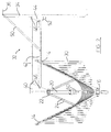
- the rotary washing line 10 comprises a frame 12 having four arms 14. It will be understood that in other embodiments the frame may have three, or more than four, arms, with three or four arms being the most likely preferred arrangements.
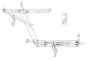
- Each of the arms 14 is pivotably mounted upon a hub bracket 16, the arms 14 being adapted to pivot between a collapsed condition ( Figs.3 , 6 ) in which they lie substantially parallel to one another and parallel to a central pole 20, and an extended condition ( Fig.1 ) in which they lie at an obtuse angle relative to one another.
- the hub bracket 16 can move relative to the central pole 20, towards and away from a link bracket 22 ( Fig.1 represents substantially the minimum possible separation between the hub bracket 16 and the link bracket 22).
- Fig.1 represents substantially the minimum possible separation between the hub bracket 16 and the link bracket 22.
- Pivotably mounted to the link bracket 22 is one end of each of four links or stays 24, the other end of each link 24 being pivotably mounted to a respective arm 14.
- the links 24 are substantially rigid, and it will be understood that movement of the hub bracket 16 towards the link bracket 22 will cause the arms 14 to pivot outwardly towards their extended condition, and vice versa.
- a length of flexible line 30 is fixed between adjacent arms, a single length of line preferably being wound in a spiral between the four arms 14. In the extended condition of Fig.1 the line 30 is substantially taut.
- a support structure 32 is provided to maintain the central pole 20 in a substantially vertical alignment in use, the support structure 32 including a wall bracket 34 whereby the rotary washing line can be mounted upon a wall (not shown) by suitable fixings 36.
- the support structure 32 also includes a support head 40 (which is securely connected to the top of the central pole 20), two support arms 42 and a support bracket 44.
- the support arms 42 are mounted to the support head 40 and the support bracket 44 by respective pivot pins 46 which are offset vertically and horizontally by identical distances so that the support arms 42 can move in a parallelogram fashion. In this way the support head 40 (and therefore also the central pole 20) maintains its chosen (preferably vertical) attitude during movement of the support structure between its storage condition (not shown) and its deployed condition.
- the wall bracket 34 has a channel (not shown) within which a part of the support bracket 44 can slide, the support bracket 44 being slidable downwardly from the deployed position shown in Figs.1 and 2 to the storage position shown in Fig.6 in which the support bracket 44 lies close to the bottom end of the wall bracket 34. It will be understood that during such downward sliding movement of the support bracket 44 the support arms 42 rotate in a clockwise direction (as drawn in Fig.2 ), the movement continuing until the support arms 42 are substantially parallel to and in close proximity to the wall bracket 34.
- the pivot pins 46 are offset horizontally by a distance slightly greater than the thickness of each support arm 42, so that the support arms 42 are kept slightly apart in the collapsed condition of Fig.6 in order to reduce the likelihood of finger-trap injuries.
- the top of the wall bracket 34 pivotably mounts one end of a link or stay 50, the other end of which is pivotably mounted upon the lowermost support arm 42.
- the link 50 is rigid, and rotates in a counter-clockwise direction (as drawn in Fig.2 ) during downwards movement of the support bracket 44 along the channel of the wall bracket 34.
- the support bracket 44 carries an operating handle 52 which is connected to a resilient stop (not shown). Within the channel of the wall bracket 34 are two recesses (also not shown) within which the resilient stop can be located, one of the recesses being adjacent to the bottom of the channel and defining the storage condition of Fig.6 , the other defining the deployed condition of Figs.1-5 .
- a resilient stop within the channel of the wall bracket 34
- two recesses also not shown
- the resilient stop within which the resilient stop can be located, one of the recesses being adjacent to the bottom of the channel and defining the storage condition of Fig.6 , the other defining the deployed condition of Figs.1-5 .
- the deployment of the support structure 32 is independent of the frame 12, i.e. as shown in Figs.3 and 6 the frame 12 remains in its collapsed condition during movement of the support structure between its storage and deployed conditions.
- the configuration of the support structure 32 is such that the central pole 20 is maintained substantially parallel to the wall bracket 34, and if the wall bracket 34 is mounted vertically as desired the central pole 20 will maintain a substantially vertical attitude. Accordingly, in the storage condition of Fig.5 the central pole 20 is substantially vertical, and the arms 14 are also substantially vertical, so that the storage volume of the rotary washing line 10 is minimised.
- the hub bracket 16 does not maintain its engagement with the central pole 20, and in the partially extended condition shown (and also in the collapsed condition of Figs. 3 and 6 ) the hub bracket 16 is free of the central pole 20.
- the central pole 20 includes a tapering bayonet structure 60 which facilitates engagement of the hub bracket 16.
- the bayonet structure 60 comprises two parts which are preferably plastic mouldings.
- the upper end of the bayonet structure is mounted around a boss 62 which is secured to the central pole 20, the mounting being such as to enable the bayonet structure 60 to rotate relatively freely around the boss 62, but to prevent relative longitudinal movement.
- the bayonet structure 60 carries a locking pin 64 which as seen in Fig.4 in this embodiment projects from both sides of the bayonet structure 60.
- the hub bracket 16 has an annular collar 66 with (in this embodiment) four channels 70 formed into its internal surface. Though not shown in these figures the channels 70 are substantially L-shaped, with a generally vertical leg communicating with the top of the hub bracket 16, connected to a generally horizontal leg.
- the hub bracket 16 can be raised from the collapsed condition of the frame 12, past the condition of Fig.2 , until it engages the bottom end of the bayonet structure 60. The hub bracket 16 can then be raised further around the tapered portion of the bayonet structure 60, with the frame 12 becoming further extended. When the frame 12 is almost fully extended the top of the hub bracket 16 lies alongside the locking pin 64, and the hub bracket 16 is rotated relative to the bayonet structure 66 until the locking pin 64 enters two of the channels 70, and is then raised further and twisted to lock the frame 12 in its extended condition as shown in Fig.1 .
- the link bracket 22 is rotatably mounted upon the central pole 20.
- the link bracket 22 is a plastic moulding having a central hole which surrounds the central pole 20.
- the link bracket 22 is mounted directly beneath the support head 40, and rests upon a flange (not shown) of the central pole, which flange results in the link bracket 22 being secured to the central pole 20.
- the bayonet structure 60 is also rotatably mounted upon the central pole 20, and since the hub 16 is secured to the bayonet structure the whole of the frame 12 can rotate around the central pole 20 when in its extended condition.
- the wall bracket 34 will be mounted so that free ends of the arms 14 in the extended condition are at around the user's head height. This is a similar height to a ground-engaging rotary washing line, and allows articles to be easy hung upon and removed from the line 30.
- the arms 14 are approximately 85 cm long, and the support arms 42 are approximately 95 cm long. It will therefore be understood that the manipulation of the operating handle 52 when the support structure 32 is in its storage condition and in its deployed condition is at a convenient height, and also that the manipulation of the hub bracket 16 during collapsing and extension of the frame 12 is at a convenient height.
- rotary washing line in its storage condition occupies a very small volume, and also occupies a very small area of a wall. This permits the rotary washing line to be installed upon a wall between two windows, or between a door and a window, even if those components are close together.
Landscapes
- Engineering & Computer Science (AREA)
- Textile Engineering (AREA)
- Supports Or Holders For Household Use (AREA)
Applications Claiming Priority (1)
| Application Number | Priority Date | Filing Date | Title |
|---|---|---|---|
| GB0813168A GB0813168D0 (en) | 2008-07-18 | 2008-07-18 | Rotary washing line |
Publications (1)
| Publication Number | Publication Date |
|---|---|
| EP2145994A1 true EP2145994A1 (fr) | 2010-01-20 |
Family
ID=39737260
Family Applications (1)
| Application Number | Title | Priority Date | Filing Date |
|---|---|---|---|
| EP09165839A Withdrawn EP2145994A1 (fr) | 2008-07-18 | 2009-07-17 | Ligne de nettoyage rotative |
Country Status (3)
| Country | Link |
|---|---|
| EP (1) | EP2145994A1 (fr) |
| AU (1) | AU2009202869A1 (fr) |
| GB (1) | GB0813168D0 (fr) |
Cited By (1)
| Publication number | Priority date | Publication date | Assignee | Title |
|---|---|---|---|---|
| PL126739U1 (pl) * | 2017-10-26 | 2019-05-06 | Dabrowski Tomasz | Suszarka sufitowa na pranie |
Citations (6)
| Publication number | Priority date | Publication date | Assignee | Title |
|---|---|---|---|---|
| US1740653A (en) * | 1929-12-24 | Drier | ||
| FR806602A (fr) | 1935-08-06 | 1936-12-21 | Dispositif de levage sur véhicules | |
| US2947424A (en) * | 1958-06-04 | 1960-08-02 | Franklin E White | Racks for linotype magazines |
| FR2151187A5 (fr) | 1971-08-24 | 1973-04-13 | Degrenne Fernand | |
| DE9321146U1 (de) * | 1993-06-08 | 1996-03-28 | Heinrich Strüwer GmbH u. Co. KG, 59457 Werl | Zusammenlegbarer Wäscheständer |
| WO2006004397A1 (fr) | 2004-07-01 | 2006-01-12 | Brabantia Nederland B.V. | Cadre pliant a montage mural, par exemple pour dispositif de sechage |
-
2008
- 2008-07-18 GB GB0813168A patent/GB0813168D0/en not_active Ceased
-
2009
- 2009-07-17 EP EP09165839A patent/EP2145994A1/fr not_active Withdrawn
- 2009-07-17 AU AU2009202869A patent/AU2009202869A1/en not_active Abandoned
Patent Citations (6)
| Publication number | Priority date | Publication date | Assignee | Title |
|---|---|---|---|---|
| US1740653A (en) * | 1929-12-24 | Drier | ||
| FR806602A (fr) | 1935-08-06 | 1936-12-21 | Dispositif de levage sur véhicules | |
| US2947424A (en) * | 1958-06-04 | 1960-08-02 | Franklin E White | Racks for linotype magazines |
| FR2151187A5 (fr) | 1971-08-24 | 1973-04-13 | Degrenne Fernand | |
| DE9321146U1 (de) * | 1993-06-08 | 1996-03-28 | Heinrich Strüwer GmbH u. Co. KG, 59457 Werl | Zusammenlegbarer Wäscheständer |
| WO2006004397A1 (fr) | 2004-07-01 | 2006-01-12 | Brabantia Nederland B.V. | Cadre pliant a montage mural, par exemple pour dispositif de sechage |
Cited By (1)
| Publication number | Priority date | Publication date | Assignee | Title |
|---|---|---|---|---|
| PL126739U1 (pl) * | 2017-10-26 | 2019-05-06 | Dabrowski Tomasz | Suszarka sufitowa na pranie |
Also Published As
| Publication number | Publication date |
|---|---|
| AU2009202869A1 (en) | 2010-02-04 |
| GB0813168D0 (en) | 2008-08-27 |
Similar Documents
| Publication | Publication Date | Title |
|---|---|---|
| US20080222909A1 (en) | Drying apparatus | |
| KR101118088B1 (ko) | 빨래 건조대 | |
| KR20110007533U (ko) | 다단 접이식 빨래 건조대 | |
| KR101656215B1 (ko) | 베란다 창틀용 세탁물 건조대 | |
| US7063220B2 (en) | Collapsible clothesline | |
| EP2145994A1 (fr) | Ligne de nettoyage rotative | |
| KR20220033388A (ko) | 벽체 고정식 빨래 건조대 | |
| US1893096A (en) | Clothes drier reel | |
| KR200462256Y1 (ko) | 건조체의 기울기 조절이 자유로운 접이식 빨래 건조대 | |
| KR200441938Y1 (ko) | 빨래 건조용 열풍 건조장치 | |
| KR200472428Y1 (ko) | 실내 부착용 접이식 세탁물 건조대 | |
| US20170188702A1 (en) | Front loading washer/dryer shelf | |
| KR20180120833A (ko) | 스탠드형 의류 건조대 | |
| KR102264484B1 (ko) | 송풍성이 개선된 빨래 건조대 | |
| KR20100010036U (ko) | 접이식 빨래건조대 | |
| KR101118208B1 (ko) | 빨래 건조대 | |
| EP1783265A1 (fr) | Séchoir pliable | |
| KR20090014836A (ko) | 접이식 세탁물 걸이대 | |
| KR20150031654A (ko) | 베란다용 세탁물건조대 | |
| KR101487428B1 (ko) | 노출식 빨래 건조대 | |
| KR200391887Y1 (ko) | 이동식 세탁물 건조대 | |
| KR100364394B1 (ko) | 가변형 옷장 | |
| KR101239285B1 (ko) | 빨래건조대 | |
| KR20160005986A (ko) | 빨래 건조대 | |
| JP7349722B2 (ja) | 物干し器具 |
Legal Events
| Date | Code | Title | Description |
|---|---|---|---|
| PUAI | Public reference made under article 153(3) epc to a published international application that has entered the european phase |
Free format text: ORIGINAL CODE: 0009012 |
|
| AK | Designated contracting states |
Kind code of ref document: A1 Designated state(s): AT BE BG CH CY CZ DE DK EE ES FI FR GB GR HR HU IE IS IT LI LT LU LV MC MK MT NL NO PL PT RO SE SI SK SM TR |
|
| AX | Request for extension of the european patent |
Extension state: AL BA RS |
|
| STAA | Information on the status of an ep patent application or granted ep patent |
Free format text: STATUS: THE APPLICATION IS DEEMED TO BE WITHDRAWN |
|
| 18D | Application deemed to be withdrawn |
Effective date: 20100721 |