EP2146004A2 - Connexion de broche travaillant en cisaillement - Google Patents
Connexion de broche travaillant en cisaillement Download PDFInfo
- Publication number
- EP2146004A2 EP2146004A2 EP09009257A EP09009257A EP2146004A2 EP 2146004 A2 EP2146004 A2 EP 2146004A2 EP 09009257 A EP09009257 A EP 09009257A EP 09009257 A EP09009257 A EP 09009257A EP 2146004 A2 EP2146004 A2 EP 2146004A2
- Authority
- EP
- European Patent Office
- Prior art keywords
- mandrel
- component
- sleeve
- connection system
- holding element
- Prior art date
- Legal status (The legal status is an assumption and is not a legal conclusion. Google has not performed a legal analysis and makes no representation as to the accuracy of the status listed.)
- Granted
Links
- 230000002787 reinforcement Effects 0.000 claims abstract description 63
- 239000000463 material Substances 0.000 claims abstract description 22
- 239000011372 high-strength concrete Substances 0.000 claims abstract description 7
- 239000011796 hollow space material Substances 0.000 claims abstract 2
- 238000006073 displacement reaction Methods 0.000 claims description 2
- 239000004567 concrete Substances 0.000 description 34
- 229910001220 stainless steel Inorganic materials 0.000 description 11
- 239000010935 stainless steel Substances 0.000 description 11
- 238000009826 distribution Methods 0.000 description 7
- 239000010426 asphalt Substances 0.000 description 6
- 239000011150 reinforced concrete Substances 0.000 description 6
- 238000004873 anchoring Methods 0.000 description 5
- 238000009434 installation Methods 0.000 description 4
- 238000004519 manufacturing process Methods 0.000 description 4
- 239000004033 plastic Substances 0.000 description 4
- 229920003023 plastic Polymers 0.000 description 4
- 238000003466 welding Methods 0.000 description 4
- 229910000831 Steel Inorganic materials 0.000 description 3
- 230000003014 reinforcing effect Effects 0.000 description 3
- 238000007789 sealing Methods 0.000 description 3
- 239000010959 steel Substances 0.000 description 3
- 239000004952 Polyamide Substances 0.000 description 2
- 229910000746 Structural steel Inorganic materials 0.000 description 2
- 239000003792 electrolyte Substances 0.000 description 2
- 238000000034 method Methods 0.000 description 2
- 229920002647 polyamide Polymers 0.000 description 2
- 230000003068 static effect Effects 0.000 description 2
- 229930195488 Arborside Natural products 0.000 description 1
- 229910001294 Reinforcing steel Inorganic materials 0.000 description 1
- 238000004026 adhesive bonding Methods 0.000 description 1
- 150000001875 compounds Chemical class 0.000 description 1
- 230000007797 corrosion Effects 0.000 description 1
- 238000005260 corrosion Methods 0.000 description 1
- 230000006735 deficit Effects 0.000 description 1
- 230000000694 effects Effects 0.000 description 1
- 239000013013 elastic material Substances 0.000 description 1
- 229920001971 elastomer Polymers 0.000 description 1
- 239000000806 elastomer Substances 0.000 description 1
- 238000009413 insulation Methods 0.000 description 1
- JEIPFZHSYJVQDO-UHFFFAOYSA-N iron(III) oxide Inorganic materials O=[Fe]O[Fe]=O JEIPFZHSYJVQDO-UHFFFAOYSA-N 0.000 description 1
- 238000010409 ironing Methods 0.000 description 1
- 238000000465 moulding Methods 0.000 description 1
- 238000005192 partition Methods 0.000 description 1
- 230000000149 penetrating effect Effects 0.000 description 1
- 239000004810 polytetrafluoroethylene Substances 0.000 description 1
- 229920001343 polytetrafluoroethylene Polymers 0.000 description 1
- 239000011371 regular concrete Substances 0.000 description 1
- 239000007787 solid Substances 0.000 description 1
- 238000004901 spalling Methods 0.000 description 1
- 230000007847 structural defect Effects 0.000 description 1
Images




Classifications
-
- E—FIXED CONSTRUCTIONS
- E01—CONSTRUCTION OF ROADS, RAILWAYS, OR BRIDGES
- E01C—CONSTRUCTION OF, OR SURFACES FOR, ROADS, SPORTS GROUNDS, OR THE LIKE; MACHINES OR AUXILIARY TOOLS FOR CONSTRUCTION OR REPAIR
- E01C11/00—Details of pavings
- E01C11/02—Arrangement or construction of joints; Methods of making joints; Packing for joints
- E01C11/04—Arrangement or construction of joints; Methods of making joints; Packing for joints for cement concrete paving
- E01C11/14—Dowel assembly ; Design or construction of reinforcements in the area of joints
-
- E—FIXED CONSTRUCTIONS
- E04—BUILDING
- E04B—GENERAL BUILDING CONSTRUCTIONS; WALLS, e.g. PARTITIONS; ROOFS; FLOORS; CEILINGS; INSULATION OR OTHER PROTECTION OF BUILDINGS
- E04B1/00—Constructions in general; Structures which are not restricted either to walls, e.g. partitions, or floors or ceilings or roofs
- E04B1/38—Connections for building structures in general
- E04B1/48—Dowels, i.e. members adapted to penetrate the surfaces of two parts and to take the shear stresses
- E04B1/483—Shear dowels to be embedded in concrete
Definitions
- the invention relates to a connection system for connecting a first component to a second component, as it is used regularly for the connection of concrete slabs, according to claim 1.
- the connection system is of the type of Schubdornthetic in which a mandrel part is arranged in one component and in the other Component a sleeve part in which the mandrel is guided in a sliding sleeve.
- the invention relates to a mandrel part and a sleeve part of such a connection system.
- a Schubdornharm of the type mentioned for the connection of two concrete slabs is from the EP 0 886 008 A1 known.
- Such Schubdorntagenen usually serve to produce expansion joints in reinforced concrete.
- Schubdorntagenen be required when relative movements of the concrete components to be joined must be made possible due to stress or thermal expansion, so that the concrete components are not damaged.
- the Schubdorntagenen serve in such systems for receiving and transmitting shear forces.
- the in the EP 0 886 008 A1 described Schubdornharm comprises an anchoring plate on which a load distribution tube is held.
- This anchoring plate surrounds the load distribution tube in the manner of a flange.
- a sliding sleeve which is held in the load distribution tube, on the front side of the component, by a solid shoulder.
- anchoring brackets are welded to the anchoring plate.
- the initially free space between sliding sleeve and load distribution pipe is poured with concrete.
- the shoulder is designed such that the forces are efficiently directed radially outwards can be.
- the load distribution in the axial direction is effected by the seated on the shoulder tube, which is filled by the on-site concrete.
- Type N thrust mandrel connections permit movement of the reinforced concrete components relative to each other in the direction of a mandrel axis of the mandrel.
- Type Q connections allow for both mandrel and transverse movement.
- Type Q connections thus have two degrees of freedom, type N connections only one degree of freedom.
- From the EP 0 773 324 A1 is a device for connecting and for absorbing transverse forces of two separated by a joint components, in which the particular concrete components are connected by means of a mandrel.
- One of the two end portions of the mandrel is embedded in the first component, while in the second component, a sleeve is inserted, in which the other of the two end portions of the mandrel penetrates.
- On the mandrel and the sleeve flange-like discs are arranged in each case in the region of the joint, which are aligned substantially perpendicular to the mandrel and sleeve and which are at least partially embedded in the corresponding components.
- the flange-like discs may be formed as part of plates, which are bent into a box profile and which have recesses for receiving anchoring brackets, by means of which the plates are cast in the concrete component.
- the mandrel is guided in the box profile both on the side facing the joint, and on the side facing away from the joint of the box profile.
- a disadvantage of this solution is that long spikes must be provided by the relatively large expansion of the boxes in the mandrel direction. These are usually made of stainless steel because they are exposed to moisture and would otherwise tend to rust. However, such long mandrels made of stainless steel are relatively expensive. Another disadvantage is that the box-like plates tend temperature and age to deformation, so that the sleeve side no proper guidance of the thrust mandrel can be guaranteed more. As a result, friction noises can occur, which continue in a building as structure-borne noise and thus lead to significant impairments or even significant structural defects.
- a fastener for concrete components is known in which a profile mandrel is provided for connecting two concrete components, which has partitions padding, which allow a certain elasticity of the concrete components relative to the fastener to reduce stress peaks in the concrete components.
- the DE 199 64 031 A1 describes a sleeve / mandrel connection for transmitting transverse forces between two adjacent components.
- the sleeve of this compound is provided on its front side with a front plate.
- the sleeve is surrounded by multiple U-shaped bent pressure distribution elements, which are also attached to the back of the face plate.
- a corresponding structure is provided for the mandrel associated with the other component.
- the DE 1 659 187 A describes a horizontally displaceable sliding anchor for transmitting vertical loads from one component to another component. It is used a rod or thorn-shaped anchor.
- This armature is arranged so that one end thereof is fixedly connected to the one component and is horizontally displaceable with the other component and rotatably connected about at least one axis.
- this armature is held movably in the other component in a sleeve firmly integrated therein.
- the sleeve contains elements that improve the slidability of the anchor therein.
- a disadvantage of the fastening element known there that it has no sufficient edge strength, so that the concrete in the region of the joint can break despite the padding.
- the concrete components can move through the required thick padding against each other in the direction of force, so that the dimensional accuracy of the components to each other is not particularly large.
- connection system of the type mentioned in that it allows a high-strength connection of the components without the risk of damage to two components, the connection system allows proper management of the mandrel and wherein the connection system is also more cost effective to produce as known from the prior art systems.
- connection system according to claim 1 and by a connection system according to the independent claim 11.
- the object is further achieved by a mandrel part according to the independent claim 14 and a sleeve part according to the independent claim 15,
- An inventive connection system for connecting a first component to a second component has a sleeve part which can be fixed by means of a reinforcement in the first component.
- the reinforcement serves to strengthen the component and gives it a higher load capacity.
- a mandrel part is provided which can be fixed in the second component by means of a reinforcement. The mandrel is feasible in the connected system of the two components in a sliding sleeve of the sleeve part.
- the holding element in the form of the rectangular profile or the trapezoidal profile has two parallel opposing surfaces. This profile is aligned parallel to the joint-side end face of the corresponding component. Such a profile is preferably used for both the sleeve part and for the mandrel part.
- the sliding sleeve of such a sleeve part then runs preferably at right angles to these parallel surfaces of the holding element.
- other profiles are possible, but two opposite, essentially should have parallel surfaces through which the sliding sleeve of the sleeve part or the mandrel of the mandrel part leads.
- Such a holding element has the further advantage that it can be arranged very close to the joint with the one surface part of the two parallel surfaces. Due to the course of the holding element parallel to the component joint, the holding element can be made very long, since it does not penetrate into the reinforcement of the component by its position on the edge of the component. Consequently, it is possible to involve a much larger area of the reinforced concrete component at the local load entry, since a larger so-called puncture cone is formed.
- the transverse force is transmitted through the joint through the mandrel.
- the holding element preferably concreted stainless steel tube
- the mandrel is guided exactly, and due to the geometry of the holding element (rectangular profile or trapezoidal profile) a clamping of the mandrel is achieved by the opposite parallel surfaces.
- the mandrel is thereby only veryrtz.vercardt directly at the gate of the component edge.
- This design of the retaining element also makes it possible to use a very short mandrel, which then does not hit the component-side reinforcement.
- the transferred transverse force can be introduced into the reinforced concrete component by welded reinforcement stirrups.
- the reinforcement may be part of an already existing component-side reinforcement or may be a reinforcement belonging to the connection system, which is integrated with the system together in the components.
- the first and the second component consist of regular concrete, reinforced concrete or other materials that are cast for the production of components.
- the two components form a joint to each other, which serves to compensate for relative movements of the two components, for example, caused by temperature changes.
- Preferred applications of the connection system thus exist in particular for components with large dimensions, which are too large Extensions to temperature changes tend, for example, bridges or larger concrete slabs in buildings.
- the gap between the components can for example be filled with an elastic material, which among other things can also have thermal insulation properties.
- a holding element for holding the sliding sleeve which consists of at least two different materials.
- at best holding elements which consist of a material, the requirements for a holding element for holding the sliding sleeve can be achieved much better with the aid of at least two different materials.
- the holding element on the one hand partly of a particularly tensile material and on the other hand partly made of a particularly pressure-resistant material, whereby the forces transmitted through the connection system forces can be absorbed particularly well on mandrel, sleeve and retaining element and forwarded into the component.
- this can also be constructed particularly compact compared to holding elements known from the prior art, which facilitates the assembly of the holding element in the production of the first component.
- this can also be constructed particularly compact compared to holding elements known from the prior art, which facilitates the assembly of the holding element in the production of the first component.
- the holding element further requires that only the joint itself must be taken into account for the static calculation of the components and the connection system, since the mandrel is so cleanly guided by the optimized holding element, that the majority of the forces on a side facing the joint of the components from the mandrel is introduced into the holding element and from there via the reinforcements in the components itself.
- the mandrel which usually consists of expensive stainless steel, can thus be designed to be particularly short; it merely has to pass completely through the retaining element even at the maximum joint.
- the holding element is designed as a hollow profile, the cavity is filled with a high-strength material, preferably high-strength concrete.
- the high-strength concrete has a particularly high compressive strength.
- the holding element then ensures that the sliding sleeve and in the sliding sleeve of the mandrel are cleanly guided, since the compact, high-strength and thus distortion-free holding element tends to much less deformation than the known in the art large-sized holding elements. This results in much lower friction stresses in the mandrel, allowing for better guidance and minimizing the occurrence of friction noise.
- the holding element is preferably made of stainless steel or stainless steel, since such a holding element can withstand better penetrating, offset with electrolyte moisture.
- the holding element is designed as a rectangular profile. Rectangular profiles are compared to other profiles, extremely compact, so that the holding element requires compared to other designs smaller space.
- the holding element can be arranged by the flat sides of the rectangular profile particularly far forward of the component boundary or joint in the first component, which reduces the load on the first component by improved power dissipation in the relevant area. It is therefore essential that the holding element is formed from a profile having two parallel surfaces.
- the Parallel surfaces are aligned parallel to the joint-side end face.
- Trapezoidal profiles allow minimizing the size of the holding part, since the trapezoid can be dimensioned according to the static loads.
- connection system provides that in the holding element a plurality of juxtaposed brackets are arranged for a plurality of mandrels.
- a holding element of greater length can be specified, in which a plurality of mandrels can be arranged and guided next to one another.
- large loads can be transmitted over several parallel mandrels without having to choose a larger mandrel diameter of a single mandrel.
- a flexible element is arranged on the holding element, which ensures a flexibility of the holding element in the edge region.
- the flexible element preferably consists of one or more strips which are arranged in areas of possible force peaks.
- a further sleeve is arranged, which has a horizontal opening, the same size or larger is considered the largest transverse dimension of the sliding sleeve.
- the opening of the further sleeve is preferably oval, slot-like or rectangular.
- the larger opening of the further sleeve allows the sliding sleeve can be received in the other sleeve, and that the sliding sleeve in the other sleeve can slide or roll.
- Oval, slot-like or rectangular openings of the further sleeve allow particularly compact designs of the further sleeve.
- the holding element and the reinforcement in the axial direction of the mandrel are connected in series.
- the holding element and reinforcement are particularly easy to connect to each other, when providing substantially the same materials, for example by welding.
- the reinforcement can also consist of structural steel, which can be welded to steel or stainless steel.
- the holding element particularly far forward in the region of the joint between the first component and the second component, preferably directly on the edge of the component.
- the reinforcement corresponds to the usual edge surrounds, so that the installation of the system is particularly easy, and that the installation of the other component-side reinforcements in areas where no Schubdorntagen is provided, not hindered is.
- a further particular advantage results if in the mandrel part, a further holding element is provided for the mandrel, which is the holding element of the sliding sleeve substantially in the different embodiments described above equivalent.
- a particularly good force introduction of the forces occurring in the second component can also be accomplished on the arbor side, so that edge chipping in the second component can likewise be prevented here and the thrust mandrel can be mounted particularly easily.
- a guide sleeve for the mandrel is provided in the mandrel part, within which the mandrel is fixable.
- the mandrel part can first be mounted without a mandrel and then insert the mandrel.
- a first independent aspect of the invention relates to a connection system for connecting a first component to a second component, which has a sleeve part which can be fixed by means of a reinforcement in the first component and which has a mandrel part which can be fixed by means of a reinforcement in the second component ,
- a mandrel of the mandrel part By a mandrel of the mandrel part, a connection between the first component and the second component can be produced, wherein the mandrel can be guided in a sliding sleeve of the sleeve part.
- the holding element and reinforcement are particularly easy to connect to each other, when providing substantially the same materials, for example by welding.
- the reinforcement can also consist of structural steel, which can be welded with steel or stainless steel.
- the holding element particularly far forward in the region of the joint between the first component and the second component, preferably directly on the edge of the component.
- the reinforcement corresponds exactly to the usual edge borders, so that the installation of the system is particularly easy, and that the installation of the other component side reinforcements in areas where no Schubdorntagen is provided, not hindered.
- the holding element and the reinforcement in the axial direction of the mandrel are connected in series. In this way, the holding element can be attach particularly easily to the reinforcement and arrange the holding element particularly far forward in the area of a joint formed between the components. This prevents spalling by force peaks on the first component and allows a particularly reliable guidance of the mandrel in the sleeve part.
- the holding element for holding the sliding sleeve is made of at least two different materials.
- the holding element on the one hand partly of a particularly tensile material and on the other hand partly made of a particularly pressure-resistant material, whereby the forces transmitted through the connection system forces can be absorbed particularly well on mandrel, sleeve and retaining element and forwarded into the component.
- this can also be constructed particularly compact compared to holding elements known from the prior art, which facilitates the assembly of the holding element in the production of the first component.
- this can also be constructed particularly compact compared to holding elements known from the prior art, which facilitates the assembly of the holding element in the production of the first component.
- connection system according to the first independent idea of the invention has one or more of the other advantageous features of the invention described first.
- Another object of the invention relates to a mandrel part of a connection system, as described above.
- a final inventive concept relates to a sleeve part of a previously described connection system.
- Fig. 1 shows an inventive connection system 2 with a sleeve part 4 and a mandrel part 6 in mutually aligned position.
- the sleeve part 4 has a sliding sleeve 8, in which a mandrel 10 is slidably guided.
- the sliding sleeve 8 is made of polyamide, which minimizes the frictional forces of the mandrel 10 in the sliding sleeve 8.
- Other suitable plastics are PTFE, PP and the like.
- the sliding sleeve 8 has an inner diameter which is slightly larger than the diameter of the mandrel 10, so that the mandrel 10 can be easily inserted into the sliding sleeve 8.
- the sliding sleeve 8 is fastened in a holding element 12, which is formed from a rectangular tube 14 made of stainless steel, which is a concrete filling 16th made of high-strength concrete. Due to the rectangular tube, the holding element 12 has parallel surfaces 14 ', parallel to the joint 44 of the two components 40; 42 are arranged, as well as in the FIGS. 3 and 4 is shown. As based on the FIG. 3 it can be seen, such a holding element 12 can be arranged very close to the joint of the two components.
- the sliding sleeve 8 extends, as the figures show, at right angles to the parallel surfaces 14 'of the support member 12 and in the direction of the surface normal of this parallel surface.
- the holding element 12 is welded to a sleeve-side reinforcement 18.
- the reinforcing brackets 18 consist of conventional reinforcing steel, for example BSt 500 S.
- the structure on the side of the mandrel part 6 is the structure of the sleeve part 4 accordingly.
- a holding element 22 is provided, which has a rectangular tube 24 which is filled with a Betonfollung 26 made of high-strength concrete.
- the mandrel 10 is fixed in the holding element 24.
- the holding element 24 is also welded on the mandrel side to a reinforcement 28, which is anchored in the corresponding component (see Fig. 3 ).
- the parallel sides of the rectangular tube, from which the holding element 24 is formed, are designated by the reference numeral 24 '.
- the mandrel 10 like the rectangular tubes 14, 24, made of stainless steel.
- brackets 18, 28 are provided for attachment. Depending on the dimensions, a plurality of brackets 18, 28 can also be welded to the retaining elements 12, 22.
- Fig. 2 shows the connection system 2 from Fig. 1 in perspective oblique view.
- the holding element 22 is connected by means of welds 30 with the brackets 28.
- Sleeve part side, the connection between the holding element 12 and ironing 18 is carried out accordingly.
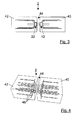
- Fig. 3 shows the connection system 2 according to the invention in a side view in the installed state.
- a first concrete slab 40 is provided on the sleeve side, a second concrete slab 42 on the thorn side.
- a gap 44 is formed between the first concrete slab 40 and the second concrete slab 42, which permits relative movements between the concrete slabs 40 and 42.
- the holding elements 12, 22 are arranged directly in the edge region of the plates 40, 42 and protrude at the joint-side end face of the concrete slabs 40, 42 up to the surface thereof. By such an arrangement, cracks in the concrete slabs 40, 42 under use load can be particularly effectively prevented.
- Fig. 4 shows the connection system 2 according to the invention in the installed state of obliquely above. Due to the compactness of the connection system 2, the rectangular tubes 14, 24 have in Schubdornraum an extension of about 20 to 40 mm, the system 2 can be easily integrated into the rest of the on-site reinforcement 46 without changes to the on-site reinforcement 46 must be made. This greatly facilitates the assembly of the connection system 2.
- the reinforcements 18, 28 belonging to the sleeve part 4 or mandrel part 6 can also be easily integrated into the usual on-site reinforcement 46.
- Fig. 5 shows an exploded view of the connection system 2 according to the invention without sleeve-side and mandrel-side reinforcement.
- the mandrel 10 is sleeve-side held in the rectangular tube 24 by means of a sleeve 50 made of polyamide or other suitable materials, whereby the mandrel 10th very easily in the rectangular tube 24 can bring and what noise generation reduces relative movements. If necessary, the plastic sleeve 50 can be dispensed with if the ambient conditions permit this, for example if corresponding noises are counteracted by other methods.
- strips 52 made of swellable bitumen can be laid onto the rectangular tubes 14, 24, as a result of which, on the one hand, a sealing effect is achieved.
- the rectangular tubes 14, 24 and the reinforcements 18, 28, 4B can be protected from corrosion, as may occur depending on the particular field of application, in particular, since the moisture usually as an aggressive electrolyte to the rectangular tubes 14, 24 and the reinforcements 18th , 28, 46, in particular when the concrete components 40, 42 have cracks.
- swellable bitumen in the swollen state has an elasticity which allows a low flexibility between the sleeve part 4 or mandrel part 6 and the concrete slabs 40, 42 under load. In this way, voltage peaks can be further reduced, so that the concrete components 40, 42 have an even lower tendency to crack.
- the sleeves are inserted in a corresponding position in the rectangular tubes 14, 24 and fastened there, preferably by clamping or gluing.
- the mandrel 10 is inserted into the plastic sleeve 50 introduced there.
- the mandrel 10 may be glued or welded in the mandrel 6, for example by spot welding.
- sealing strips 52 are applied to the rectangular tubes 14, 24. Subsequently, the cavities 54 of the rectangular tubes are potted with high-strength concrete ( Fig. 6 ). Sleeve part 4 and mandrel part 6 can be prepared in this form factory side and used element by element at the site.
- connection system 2 The prepared components of the connection system 2 are integrated into the on-site reinforcement 46 or welded to the on-site reinforcement 46, wherein the mandrel 10 of the mandrel part 6 is inserted into the sleeve 8 of the sleeve part 4. Then the reinforcement is boarded and poured with concrete.
- the rectangular tubes 14, 24 are positioned adjacent to a casing.
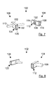
- FIGS. 7 to 9 show a second embodiment of the invention, in which a connection system 102 is indicated, which has a sleeve portion 104 and a mandrel portion 106, wherein the sleeve portion 104, two sleeves 108, 109 which are guided into each other.
- the additional sleeve 109 is slot-shaped and has a clear width which is greater than the largest extension of the sleeve 108, so that the sleeve 108 in the sleeve 109 can slide or roll. In this way, a relative movement of the components to be joined is made possible, which is useful for very large plates, in particular thermal expansion, since the components usually extend in all directions. All other components correspond to the components according to the first embodiment.
- Fig. 8 shows the system 102 as viewed from the sleeve portion 104.
- Fig. 9 shows the system 102 including reinforcements 118, 128, which are defined by means of welds 130 on the rectangular tubes 114, 124.
- FIGS. 10 . 11 and 12 show a third embodiment of the invention, according to which a connection system 202 is given, which is opposite to in the FIGS. 1 to 7 shown differs in that on the part of the sleeve part 204 and the side of the mandrel part 206 a plurality of sleeves 208, 209 are provided for a plurality of mandrels 210, 211.
- the illustrated embodiment according to FIGS. 10 to 12 is just an example, it can too Connection systems are specified with any number of sleeves and a corresponding number of thorns. With the help of the modular design can be compared to the known Schubdorntagenen transfer significantly higher forces, since with separate Schubdorntagenen a minimum distance must be maintained in order to maintain the structural strength.
- Fig. 11 are corresponding to the number of sleeves 208, 209 and mandrels 210, 211 correspondingly more reinforcing bracket 218, 228 provided.
- Fig. 12 shows the connection system 202 in the assembled state, as it is integrated in the on-site reinforcement 246.
- Fig. 13 shows another connection system 262 in a representation that corresponds to that of Fig. 6 is comparable. Compared to the connection system 2 of Fig. 6 rejects the connection system 262 Fig. 13 Holding elements 12 and 22 which are associated with the sleeve part 4 and the mandrel part 6, which are formed from a trapezoidal profile 263. It is essential that this trapezoidal profile 263 has two parallel side surfaces 263 '. In Fig. 13 It can be seen that this trapezoidal profile is oriented so that the smaller area points to the joint of the interconnected components. This has the advantage that the large area is available as a surface for welding the reinforcement parts. The trapezoidal profile 263 could also be rotated so that the large area faces the joint.
- connection system 116 concrete filling 4 sleeve part 118
Landscapes
- Engineering & Computer Science (AREA)
- Architecture (AREA)
- Civil Engineering (AREA)
- Structural Engineering (AREA)
- Physics & Mathematics (AREA)
- Electromagnetism (AREA)
- Bridges Or Land Bridges (AREA)
- Joining Of Building Structures In Genera (AREA)
- Reinforcement Elements For Buildings (AREA)
- Snaps, Bayonet Connections, Set Pins, And Snap Rings (AREA)
- Insertion Pins And Rivets (AREA)
Applications Claiming Priority (1)
| Application Number | Priority Date | Filing Date | Title |
|---|---|---|---|
| DE200810033585 DE102008033585B4 (de) | 2008-07-17 | 2008-07-17 | Schubdornverbindung |
Publications (3)
| Publication Number | Publication Date |
|---|---|
| EP2146004A2 true EP2146004A2 (fr) | 2010-01-20 |
| EP2146004A3 EP2146004A3 (fr) | 2012-01-04 |
| EP2146004B1 EP2146004B1 (fr) | 2015-11-04 |
Family
ID=40935786
Family Applications (1)
| Application Number | Title | Priority Date | Filing Date |
|---|---|---|---|
| EP09009257.8A Not-in-force EP2146004B1 (fr) | 2008-07-17 | 2009-07-16 | Connexion de broche travaillant en cisaillement |
Country Status (3)
| Country | Link |
|---|---|
| EP (1) | EP2146004B1 (fr) |
| DE (1) | DE102008033585B4 (fr) |
| ES (1) | ES2556241T3 (fr) |
Cited By (2)
| Publication number | Priority date | Publication date | Assignee | Title |
|---|---|---|---|---|
| WO2012025106A3 (fr) * | 2010-05-21 | 2012-05-10 | Max Frank Gmbh & Co. Kg | Dispositif permettant de raccorder deux éléments de construction séparés par un joint et d'absorber des efforts de cisaillement apparaissant entre les éléments de construction |
| CN105220834A (zh) * | 2015-10-09 | 2016-01-06 | 姜超 | 一种建筑混凝土增强部件 |
Families Citing this family (3)
| Publication number | Priority date | Publication date | Assignee | Title |
|---|---|---|---|---|
| DE102010003785A1 (de) * | 2010-04-09 | 2011-10-13 | Ed. Züblin Ag | Betonformteilverbindung |
| DE102020005274A1 (de) | 2020-08-28 | 2022-03-03 | H-Bau Technik Gmbh | Vorrichtung zur Querkraftverbindung eines ersten Bauteils aus Beton mit einem zweiten Bauteil |
| DE102024101963A1 (de) | 2024-01-24 | 2025-07-24 | Pfeifer Holding Gmbh & Co. Kg | Verbindungssystem für tragelemente |
Citations (5)
| Publication number | Priority date | Publication date | Assignee | Title |
|---|---|---|---|---|
| DE1659187A1 (de) | 1968-01-17 | 1970-12-23 | Nell Dipl Ing Hans Alfred | Horizontal verschiebbarer Gleitanker zur UEbertragung von Vertikallasten von einem Bauteil auf ein anderes Bauteil |
| EP0773324A1 (fr) | 1995-11-07 | 1997-05-14 | F.J. Aschwanden AG | Dispositif pour la connection et la transmission des forces transversales entre deux structures séparées par un joint |
| EP0886008A1 (fr) | 1997-06-20 | 1998-12-23 | Toni H. Erb | Piece pour mandrin d'attache travaillant en cisaillement |
| DE19964031A1 (de) | 1999-12-30 | 2001-07-05 | Schoeck Bauteile Gmbh | Hülsen-/Dorn-Verbindung zwischen benachbarten Bauteilen |
| EP1477620A1 (fr) | 2003-05-12 | 2004-11-17 | Ankaba Ankertechnik und Bauhandel AG | Dispositif d'ancrage pour éléments de construction en béton et son utilisation |
Family Cites Families (4)
| Publication number | Priority date | Publication date | Assignee | Title |
|---|---|---|---|---|
| CH651090A5 (de) * | 1980-01-04 | 1985-08-30 | Ulisse Claudio Aschwanden | Dorn und huelse zur verbindung von bauteilen des hoch- und tiefbaues. |
| CH659101A5 (de) * | 1982-12-01 | 1986-12-31 | Anton Erb | Schubduebel. |
| CH692991A5 (de) * | 1997-11-17 | 2003-01-15 | Pecon Ag | Querkraftdornlagerung. |
| DK0943744T3 (da) * | 1998-03-20 | 2004-06-07 | Reto Bonomo | Fremgangsmåde og element til indföring af forskydningskræfter i et betonlegeme og et armeret betonlegeme |
-
2008
- 2008-07-17 DE DE200810033585 patent/DE102008033585B4/de not_active Expired - Fee Related
-
2009
- 2009-07-16 ES ES09009257.8T patent/ES2556241T3/es active Active
- 2009-07-16 EP EP09009257.8A patent/EP2146004B1/fr not_active Not-in-force
Patent Citations (5)
| Publication number | Priority date | Publication date | Assignee | Title |
|---|---|---|---|---|
| DE1659187A1 (de) | 1968-01-17 | 1970-12-23 | Nell Dipl Ing Hans Alfred | Horizontal verschiebbarer Gleitanker zur UEbertragung von Vertikallasten von einem Bauteil auf ein anderes Bauteil |
| EP0773324A1 (fr) | 1995-11-07 | 1997-05-14 | F.J. Aschwanden AG | Dispositif pour la connection et la transmission des forces transversales entre deux structures séparées par un joint |
| EP0886008A1 (fr) | 1997-06-20 | 1998-12-23 | Toni H. Erb | Piece pour mandrin d'attache travaillant en cisaillement |
| DE19964031A1 (de) | 1999-12-30 | 2001-07-05 | Schoeck Bauteile Gmbh | Hülsen-/Dorn-Verbindung zwischen benachbarten Bauteilen |
| EP1477620A1 (fr) | 2003-05-12 | 2004-11-17 | Ankaba Ankertechnik und Bauhandel AG | Dispositif d'ancrage pour éléments de construction en béton et son utilisation |
Cited By (2)
| Publication number | Priority date | Publication date | Assignee | Title |
|---|---|---|---|---|
| WO2012025106A3 (fr) * | 2010-05-21 | 2012-05-10 | Max Frank Gmbh & Co. Kg | Dispositif permettant de raccorder deux éléments de construction séparés par un joint et d'absorber des efforts de cisaillement apparaissant entre les éléments de construction |
| CN105220834A (zh) * | 2015-10-09 | 2016-01-06 | 姜超 | 一种建筑混凝土增强部件 |
Also Published As
| Publication number | Publication date |
|---|---|
| EP2146004A3 (fr) | 2012-01-04 |
| ES2556241T3 (es) | 2016-01-14 |
| EP2146004B1 (fr) | 2015-11-04 |
| DE102008033585A1 (de) | 2010-02-18 |
| DE102008033585B4 (de) | 2010-04-29 |
Similar Documents
| Publication | Publication Date | Title |
|---|---|---|
| EP2686497B1 (fr) | Module de paroi pour la construction d'un ouvrage | |
| EP1505223B1 (fr) | Tendon protégé contre la corrosion, en particulier pour béton précontraint | |
| AT390101B (de) | Zwischenankeranordnung zum vorspannen von bauteilen und ein verfahren zum herstellen solcher zwischenankeranordnungen | |
| AT516415B1 (de) | Verbindungsvorrichtung zur mechanischen Kopplung von Betonplatten, sowie damit aufgebaute Betonwand | |
| EP4036338B1 (fr) | Dispositif de raccordement ultérieur à isolation thermique et à transfert de force d'une seconde partie d'ouvrage supportant la charge à une première partie d'ouvrage supportant la charge et ouvrage doté d'un tel dispositif | |
| DE2727286A1 (de) | Verfahren und vorrichtung zum verbinden flaechenfoermiger bauelemente | |
| EP2146004B1 (fr) | Connexion de broche travaillant en cisaillement | |
| EP0773324B1 (fr) | Dispositif pour la connection et la transmission des forces transversales entre deux structures séparées par un joint | |
| EP3336269B1 (fr) | Élément de construction destiné a l'isolation thermique | |
| EP2486196A2 (fr) | Procédé et dispositif pour l'ajout postérieur d'une partie extérieure en saillie à une partie de bâtiment existante | |
| EP2436845B1 (fr) | Dispositif de raccordement forcé d'un composant sur un corps de construction, notamment d'un balcon sur un bâtiment | |
| DE102011115772A1 (de) | Gerüstanker mit Gerüstabstützung für Wärmedämmverbundsysteme | |
| DE102019133999A1 (de) | Anordnung zum Verbinden eines Bauwerkteils mit einem dem Bauwerkteil vorgelagerten Außenteil | |
| EP1088943A2 (fr) | Support de montage avec accessoire de montage | |
| DE3302075C2 (de) | Verbindung für Spannbeton- oder Stahlbetonbiegeträger | |
| DE2732183A1 (de) | Stossverbindung von teilen aus stahlbeton | |
| EP1847666A1 (fr) | Dispositif d'ancrage pour lier des planches de coffrage | |
| EP1887155B1 (fr) | Elément d'isolation thermique | |
| EP1063361A2 (fr) | Gabarit de montage et procédé de montage d'un élément préfabriqué sur une partie de bâtiment | |
| EP2873778A1 (fr) | Agencement de liaison et système de liaison pour pièces finies en béton | |
| EP2607560A2 (fr) | Elément de raccordement de dalle | |
| EP3835501B1 (fr) | Arrangement pour connecter une pièce de construction avec une partie extérieure frontale | |
| DE102011056105B4 (de) | Montagezusatzelement für die Befestigung von Bauelementen, z.B. Kellerlichtschächten an Gebäudewänden | |
| EP4592465A1 (fr) | Système de liaison pour éléments porteurs | |
| DE102016113558A1 (de) | Bauelement zur Wärmedämmung |
Legal Events
| Date | Code | Title | Description |
|---|---|---|---|
| PUAI | Public reference made under article 153(3) epc to a published international application that has entered the european phase |
Free format text: ORIGINAL CODE: 0009012 |
|
| AK | Designated contracting states |
Kind code of ref document: A2 Designated state(s): AT BE BG CH CY CZ DE DK EE ES FI FR GB GR HR HU IE IS IT LI LT LU LV MC MK MT NL NO PL PT RO SE SI SK SM TR |
|
| AX | Request for extension of the european patent |
Extension state: AL BA RS |
|
| RIC1 | Information provided on ipc code assigned before grant |
Ipc: E04B 1/48 20060101ALI20110809BHEP Ipc: E01C 11/14 20060101AFI20110809BHEP Ipc: E04C 5/06 20060101ALI20110809BHEP |
|
| PUAL | Search report despatched |
Free format text: ORIGINAL CODE: 0009013 |
|
| AK | Designated contracting states |
Kind code of ref document: A3 Designated state(s): AT BE BG CH CY CZ DE DK EE ES FI FR GB GR HR HU IE IS IT LI LT LU LV MC MK MT NL NO PL PT RO SE SI SK SM TR |
|
| AX | Request for extension of the european patent |
Extension state: AL BA RS |
|
| RIC1 | Information provided on ipc code assigned before grant |
Ipc: E01C 11/14 20060101AFI20111201BHEP Ipc: E04C 5/06 20060101ALI20111201BHEP Ipc: E04B 1/48 20060101ALI20111201BHEP |
|
| 17P | Request for examination filed |
Effective date: 20120618 |
|
| GRAP | Despatch of communication of intention to grant a patent |
Free format text: ORIGINAL CODE: EPIDOSNIGR1 |
|
| INTG | Intention to grant announced |
Effective date: 20150616 |
|
| RAP1 | Party data changed (applicant data changed or rights of an application transferred) |
Owner name: IKONA AG |
|
| GRAS | Grant fee paid |
Free format text: ORIGINAL CODE: EPIDOSNIGR3 |
|
| GRAA | (expected) grant |
Free format text: ORIGINAL CODE: 0009210 |
|
| AK | Designated contracting states |
Kind code of ref document: B1 Designated state(s): AT BE BG CH CY CZ DE DK EE ES FI FR GB GR HR HU IE IS IT LI LT LU LV MC MK MT NL NO PL PT RO SE SI SK SM TR |
|
| REG | Reference to a national code |
Ref country code: GB Ref legal event code: FG4D Free format text: NOT ENGLISH |
|
| REG | Reference to a national code |
Ref country code: CH Ref legal event code: EP |
|
| REG | Reference to a national code |
Ref country code: AT Ref legal event code: REF Ref document number: 759278 Country of ref document: AT Kind code of ref document: T Effective date: 20151115 |
|
| REG | Reference to a national code |
Ref country code: IE Ref legal event code: FG4D Free format text: LANGUAGE OF EP DOCUMENT: GERMAN |
|
| REG | Reference to a national code |
Ref country code: DE Ref legal event code: R096 Ref document number: 502009011784 Country of ref document: DE |
|
| REG | Reference to a national code |
Ref country code: ES Ref legal event code: FG2A Ref document number: 2556241 Country of ref document: ES Kind code of ref document: T3 Effective date: 20160114 |
|
| REG | Reference to a national code |
Ref country code: LT Ref legal event code: MG4D |
|
| REG | Reference to a national code |
Ref country code: NL Ref legal event code: FP |
|
| PG25 | Lapsed in a contracting state [announced via postgrant information from national office to epo] |
Ref country code: NO Free format text: LAPSE BECAUSE OF FAILURE TO SUBMIT A TRANSLATION OF THE DESCRIPTION OR TO PAY THE FEE WITHIN THE PRESCRIBED TIME-LIMIT Effective date: 20160204 Ref country code: IT Free format text: LAPSE BECAUSE OF FAILURE TO SUBMIT A TRANSLATION OF THE DESCRIPTION OR TO PAY THE FEE WITHIN THE PRESCRIBED TIME-LIMIT Effective date: 20151104 Ref country code: IS Free format text: LAPSE BECAUSE OF FAILURE TO SUBMIT A TRANSLATION OF THE DESCRIPTION OR TO PAY THE FEE WITHIN THE PRESCRIBED TIME-LIMIT Effective date: 20160304 Ref country code: HR Free format text: LAPSE BECAUSE OF FAILURE TO SUBMIT A TRANSLATION OF THE DESCRIPTION OR TO PAY THE FEE WITHIN THE PRESCRIBED TIME-LIMIT Effective date: 20151104 Ref country code: LT Free format text: LAPSE BECAUSE OF FAILURE TO SUBMIT A TRANSLATION OF THE DESCRIPTION OR TO PAY THE FEE WITHIN THE PRESCRIBED TIME-LIMIT Effective date: 20151104 |
|
| PG25 | Lapsed in a contracting state [announced via postgrant information from national office to epo] |
Ref country code: PT Free format text: LAPSE BECAUSE OF FAILURE TO SUBMIT A TRANSLATION OF THE DESCRIPTION OR TO PAY THE FEE WITHIN THE PRESCRIBED TIME-LIMIT Effective date: 20160304 Ref country code: FI Free format text: LAPSE BECAUSE OF FAILURE TO SUBMIT A TRANSLATION OF THE DESCRIPTION OR TO PAY THE FEE WITHIN THE PRESCRIBED TIME-LIMIT Effective date: 20151104 Ref country code: SE Free format text: LAPSE BECAUSE OF FAILURE TO SUBMIT A TRANSLATION OF THE DESCRIPTION OR TO PAY THE FEE WITHIN THE PRESCRIBED TIME-LIMIT Effective date: 20151104 Ref country code: PL Free format text: LAPSE BECAUSE OF FAILURE TO SUBMIT A TRANSLATION OF THE DESCRIPTION OR TO PAY THE FEE WITHIN THE PRESCRIBED TIME-LIMIT Effective date: 20151104 Ref country code: LV Free format text: LAPSE BECAUSE OF FAILURE TO SUBMIT A TRANSLATION OF THE DESCRIPTION OR TO PAY THE FEE WITHIN THE PRESCRIBED TIME-LIMIT Effective date: 20151104 |
|
| PG25 | Lapsed in a contracting state [announced via postgrant information from national office to epo] |
Ref country code: CZ Free format text: LAPSE BECAUSE OF FAILURE TO SUBMIT A TRANSLATION OF THE DESCRIPTION OR TO PAY THE FEE WITHIN THE PRESCRIBED TIME-LIMIT Effective date: 20151104 |
|
| REG | Reference to a national code |
Ref country code: DE Ref legal event code: R097 Ref document number: 502009011784 Country of ref document: DE |
|
| PG25 | Lapsed in a contracting state [announced via postgrant information from national office to epo] |
Ref country code: SK Free format text: LAPSE BECAUSE OF FAILURE TO SUBMIT A TRANSLATION OF THE DESCRIPTION OR TO PAY THE FEE WITHIN THE PRESCRIBED TIME-LIMIT Effective date: 20151104 Ref country code: SM Free format text: LAPSE BECAUSE OF FAILURE TO SUBMIT A TRANSLATION OF THE DESCRIPTION OR TO PAY THE FEE WITHIN THE PRESCRIBED TIME-LIMIT Effective date: 20151104 Ref country code: EE Free format text: LAPSE BECAUSE OF FAILURE TO SUBMIT A TRANSLATION OF THE DESCRIPTION OR TO PAY THE FEE WITHIN THE PRESCRIBED TIME-LIMIT Effective date: 20151104 Ref country code: RO Free format text: LAPSE BECAUSE OF FAILURE TO SUBMIT A TRANSLATION OF THE DESCRIPTION OR TO PAY THE FEE WITHIN THE PRESCRIBED TIME-LIMIT Effective date: 20151104 Ref country code: DK Free format text: LAPSE BECAUSE OF FAILURE TO SUBMIT A TRANSLATION OF THE DESCRIPTION OR TO PAY THE FEE WITHIN THE PRESCRIBED TIME-LIMIT Effective date: 20151104 |
|
| PLBE | No opposition filed within time limit |
Free format text: ORIGINAL CODE: 0009261 |
|
| STAA | Information on the status of an ep patent application or granted ep patent |
Free format text: STATUS: NO OPPOSITION FILED WITHIN TIME LIMIT |
|
| 26N | No opposition filed |
Effective date: 20160805 |
|
| PG25 | Lapsed in a contracting state [announced via postgrant information from national office to epo] |
Ref country code: SI Free format text: LAPSE BECAUSE OF FAILURE TO SUBMIT A TRANSLATION OF THE DESCRIPTION OR TO PAY THE FEE WITHIN THE PRESCRIBED TIME-LIMIT Effective date: 20151104 |
|
| PG25 | Lapsed in a contracting state [announced via postgrant information from national office to epo] |
Ref country code: BE Free format text: LAPSE BECAUSE OF NON-PAYMENT OF DUE FEES Effective date: 20160731 |
|
| REG | Reference to a national code |
Ref country code: NL Ref legal event code: MM Effective date: 20160801 |
|
| GBPC | Gb: european patent ceased through non-payment of renewal fee |
Effective date: 20160716 |
|
| PG25 | Lapsed in a contracting state [announced via postgrant information from national office to epo] |
Ref country code: MC Free format text: LAPSE BECAUSE OF FAILURE TO SUBMIT A TRANSLATION OF THE DESCRIPTION OR TO PAY THE FEE WITHIN THE PRESCRIBED TIME-LIMIT Effective date: 20151104 |
|
| PG25 | Lapsed in a contracting state [announced via postgrant information from national office to epo] |
Ref country code: NL Free format text: LAPSE BECAUSE OF NON-PAYMENT OF DUE FEES Effective date: 20160801 Ref country code: FR Free format text: LAPSE BECAUSE OF NON-PAYMENT OF DUE FEES Effective date: 20160801 |
|
| REG | Reference to a national code |
Ref country code: FR Ref legal event code: ST Effective date: 20170331 |
|
| REG | Reference to a national code |
Ref country code: IE Ref legal event code: MM4A |
|
| PG25 | Lapsed in a contracting state [announced via postgrant information from national office to epo] |
Ref country code: GB Free format text: LAPSE BECAUSE OF NON-PAYMENT OF DUE FEES Effective date: 20160716 |
|
| PG25 | Lapsed in a contracting state [announced via postgrant information from national office to epo] |
Ref country code: IE Free format text: LAPSE BECAUSE OF NON-PAYMENT OF DUE FEES Effective date: 20160716 |
|
| PG25 | Lapsed in a contracting state [announced via postgrant information from national office to epo] |
Ref country code: LU Free format text: LAPSE BECAUSE OF NON-PAYMENT OF DUE FEES Effective date: 20160716 |
|
| REG | Reference to a national code |
Ref country code: AT Ref legal event code: MM01 Ref document number: 759278 Country of ref document: AT Kind code of ref document: T Effective date: 20160716 |
|
| PG25 | Lapsed in a contracting state [announced via postgrant information from national office to epo] |
Ref country code: AT Free format text: LAPSE BECAUSE OF NON-PAYMENT OF DUE FEES Effective date: 20160716 |
|
| PG25 | Lapsed in a contracting state [announced via postgrant information from national office to epo] |
Ref country code: HU Free format text: LAPSE BECAUSE OF FAILURE TO SUBMIT A TRANSLATION OF THE DESCRIPTION OR TO PAY THE FEE WITHIN THE PRESCRIBED TIME-LIMIT; INVALID AB INITIO Effective date: 20090716 Ref country code: ES Free format text: LAPSE BECAUSE OF NON-PAYMENT OF DUE FEES Effective date: 20160717 Ref country code: CY Free format text: LAPSE BECAUSE OF FAILURE TO SUBMIT A TRANSLATION OF THE DESCRIPTION OR TO PAY THE FEE WITHIN THE PRESCRIBED TIME-LIMIT Effective date: 20151104 |
|
| PG25 | Lapsed in a contracting state [announced via postgrant information from national office to epo] |
Ref country code: TR Free format text: LAPSE BECAUSE OF FAILURE TO SUBMIT A TRANSLATION OF THE DESCRIPTION OR TO PAY THE FEE WITHIN THE PRESCRIBED TIME-LIMIT Effective date: 20151104 Ref country code: MT Free format text: LAPSE BECAUSE OF FAILURE TO SUBMIT A TRANSLATION OF THE DESCRIPTION OR TO PAY THE FEE WITHIN THE PRESCRIBED TIME-LIMIT Effective date: 20151104 Ref country code: GR Free format text: LAPSE BECAUSE OF FAILURE TO SUBMIT A TRANSLATION OF THE DESCRIPTION OR TO PAY THE FEE WITHIN THE PRESCRIBED TIME-LIMIT Effective date: 20151104 Ref country code: MK Free format text: LAPSE BECAUSE OF FAILURE TO SUBMIT A TRANSLATION OF THE DESCRIPTION OR TO PAY THE FEE WITHIN THE PRESCRIBED TIME-LIMIT Effective date: 20151104 |
|
| PG25 | Lapsed in a contracting state [announced via postgrant information from national office to epo] |
Ref country code: BG Free format text: LAPSE BECAUSE OF FAILURE TO SUBMIT A TRANSLATION OF THE DESCRIPTION OR TO PAY THE FEE WITHIN THE PRESCRIBED TIME-LIMIT Effective date: 20151104 |
|
| REG | Reference to a national code |
Ref country code: ES Ref legal event code: FD2A Effective date: 20181126 |
|
| PGFP | Annual fee paid to national office [announced via postgrant information from national office to epo] |
Ref country code: CH Payment date: 20210721 Year of fee payment: 13 |
|
| PGFP | Annual fee paid to national office [announced via postgrant information from national office to epo] |
Ref country code: DE Payment date: 20220731 Year of fee payment: 14 |
|
| REG | Reference to a national code |
Ref country code: CH Ref legal event code: PL |
|
| PG25 | Lapsed in a contracting state [announced via postgrant information from national office to epo] |
Ref country code: LI Free format text: LAPSE BECAUSE OF NON-PAYMENT OF DUE FEES Effective date: 20220731 Ref country code: CH Free format text: LAPSE BECAUSE OF NON-PAYMENT OF DUE FEES Effective date: 20220731 |
|
| P01 | Opt-out of the competence of the unified patent court (upc) registered |
Effective date: 20230530 |
|
| REG | Reference to a national code |
Ref country code: DE Ref legal event code: R119 Ref document number: 502009011784 Country of ref document: DE |
|
| PG25 | Lapsed in a contracting state [announced via postgrant information from national office to epo] |
Ref country code: DE Free format text: LAPSE BECAUSE OF NON-PAYMENT OF DUE FEES Effective date: 20240201 |