EP2146010A1 - Raccord - Google Patents
Raccord Download PDFInfo
- Publication number
- EP2146010A1 EP2146010A1 EP09009270A EP09009270A EP2146010A1 EP 2146010 A1 EP2146010 A1 EP 2146010A1 EP 09009270 A EP09009270 A EP 09009270A EP 09009270 A EP09009270 A EP 09009270A EP 2146010 A1 EP2146010 A1 EP 2146010A1
- Authority
- EP
- European Patent Office
- Prior art keywords
- fitting
- fitting according
- bore
- closure body
- connection
- Prior art date
- Legal status (The legal status is an assumption and is not a legal conclusion. Google has not performed a legal analysis and makes no representation as to the accuracy of the status listed.)
- Withdrawn
Links
- 239000007788 liquid Substances 0.000 claims abstract description 8
- 230000001105 regulatory effect Effects 0.000 claims abstract description 5
- 238000007789 sealing Methods 0.000 claims description 41
- 238000009434 installation Methods 0.000 claims description 5
- 230000001681 protective effect Effects 0.000 claims description 2
- XLYOFNOQVPJJNP-UHFFFAOYSA-N water Substances O XLYOFNOQVPJJNP-UHFFFAOYSA-N 0.000 description 16
- 239000011505 plaster Substances 0.000 description 6
- 230000006835 compression Effects 0.000 description 4
- 238000007906 compression Methods 0.000 description 4
- 239000000919 ceramic Substances 0.000 description 3
- 238000004026 adhesive bonding Methods 0.000 description 1
- 238000010276 construction Methods 0.000 description 1
- 230000002950 deficient Effects 0.000 description 1
- 239000004570 mortar (masonry) Substances 0.000 description 1
- 210000002445 nipple Anatomy 0.000 description 1
- 238000005476 soldering Methods 0.000 description 1
Images






Classifications
-
- E—FIXED CONSTRUCTIONS
- E03—WATER SUPPLY; SEWERAGE
- E03C—DOMESTIC PLUMBING INSTALLATIONS FOR FRESH WATER OR WASTE WATER; SINKS
- E03C1/00—Domestic plumbing installations for fresh water or waste water; Sinks
- E03C1/02—Plumbing installations for fresh water
- E03C1/021—Devices for positioning or connecting of water supply lines
Definitions
- the invention relates to a fitting for the pipe installation with at least two terminals.
- a fitting such as a connection bend, a connection bracket or a branch.
- the fitting is connected to a terminal by pressing, plugging, soldering, gluing or screwing to one end of the tube. It is threaded for connection to a device such as a faucet or heater.
- the fitting is normally located with its connection side flush with the outside of the wall or protrudes out of the wall.
- the pipe system then remains under pressure until completion of further work, for example tiling in a bath.
- the closure is removed, the tube system emptied and the device screwed.
- the pipe system is pressurized again and the device and its connections checked for leaks. If the device is leaking or defective and must therefore be re-sealed or replaced, the pipe system must be emptied again to remove the device. It is pressurized again after the device has been replaced.
- the invention has for its object to simplify the review and installation of the pipe system and the device.
- the fitting has a device for regulating the flow of a gas or a liquid.
- the fitting can be completely closed by means of the device and opened in a controlled manner so that the amount of liquid or gas flowing through the fitting per unit of time can be adjusted.
- the device is first closed and the pipe system is then pressurized for pressure testing. The closures mentioned are no longer needed.
- the device is opened and the device can be checked. If the device is to be repaired or replaced, it is sufficient to close or open the device of the fitting.
- the pipe system does not have to be emptied and refilled.
- angle valves which are normally used to connect the device, can be saved.
- the connection of the device is connected directly to the connection of the fitting according to the invention.
- the fitting is provided on at least one connection side with a thread.
- the device has a closure body arranged in the fitting.
- the fitting according to the invention can thus be made in the size of a conventional fitting and used as such.
- the device has an adjusting device arranged next to one of the connections for the closure body.
- the device can be adjusted from the side to which the device is connected and, in particular when the fitting is arranged in a wall in the plaster or offset behind tiles, are operated without the device must be removed.
- the fitting is formed from two parts and the two parts are, preferably sealing, plugged into each other or screwed.
- One of the parts has at least one connection, the closure body and the adjusting device, and the other part has a different connection or other connections and is provided for receiving the other part, preferably with an internal thread.
- the former part can be exchanged if, for example, due to a replacement of a device other thread sizes are needed.
- a lever or a rotatable rod or shaft is provided for opening or closing the fitting or adjusting the device.
- the lever is preferably provided on the lever attachable handle.
- the rod or the shaft preferably has a recess into which a tool, for example a screwdriver or an Allen key, finds a seat and by means of which the rod or shaft can be rotated.
- said closure body is a sealing disc closing a conduit opening of the fitting.
- the sealing disc is steplessly pivotable over the conduit opening and can preferably fully release it.
- the sealing disc is provided with a recess which can be pivoted over the bore of the fitting.
- the closure body is provided with a bore ball.
- the bore of the ball is offset from its center and preferably has a semi-circular cross-section. If the connections are arranged at right angles to one another in the fitting, the device with a ball designed in this way can already be brought into the fully open position by turning the ball by only about 45 ° from the closed position.
- the closure body is provided with a bore cylinder.
- the bore of the cylinder is suitably angled and preferably extends partially axially and partially radially in the cylinder.
- the axial bore on the The conduit opening of the fitting moves to open the fitting.
- the cylinder is rotated so that the cylinder jacket surface closes off the pipe opening.
- the fitting has three connections and, for the line connection of two connections, a recess is provided on an outer surface of the cylinder, preferably approximately one third of its circumference. It is advantageously possible to set which connections of the fitting are to be connected to one another.
- the closure body has a sealing washer which has a larger radius than the opening and is pressed onto the conduit opening for closing.
- the closure body can be arranged at different distances from the conduit opening.
- the fitting is particularly easy to regulate when the closure body is held by a spring in its closed position and the spring is supported on an adjustable support, by means of which the positions of the closure body and / or the pressure is under which the spring is adjustable.
- the holder preferably has a rod connected to the closure body, a cylinder provided with a bore receiving the rod and a U-shaped plate on which the rod is held at one end thereof. To set the position of the closure body, the holder in relation to the conduit opening and the closure body in relation to the holder, preferably by a knurled nut to be moved.
- connection of the fitting can be adapted to the position of the device.
- a connection fitting is provided with two fittings according to the invention.
- the fittings are provided with three pipe openings, with the two fittings via one of the pipe openings with each other are connected.
- the device is adjustable such that the gas or liquid is passed either through the connection provided for connection with a device through the first fitting into a device and from there via the corresponding connection in the second fitting and runs back to a part of the conductive Gas or liquid passes through the pipe connecting the fittings or the gas or liquid is passed exclusively through the pipe connecting the fittings and a device connected to the fittings is completed.
- devices connected in series can be separated individually from a gas or water supply and the other devices can continue to be operated.
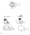
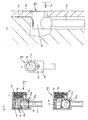
- FIG. 1 an inventive fitting 1 is shown, the two, in the FIGS. 1a and 1b in side view in section parts shown 60,61, which, like Fig. 1c shows, can be screwed together.
- the fitting 1 has on the lower side of the part 60 a port which is mounted on a pipeline.
- the part 61 is provided with a connection 3 with an internal thread, with which the fitting 1 can be connected to a device.
- a hole 2 connects.
- an oval recess having a sealing washer 16 is arranged at the side facing away from the connection 3 of the bore 2.
- a plate 4 which is also oval in shape but slightly larger than the recess in the sealing disc sixteenth
- the plate 4 is connected on one side with a rod 5, which serves as an adjusting device for the plate 4.
- the rod 5 is guided in a bore in the fitting 1, which leads to the front of the fitting 1, on which the threaded connection 3 is arranged.
- a recess for the engagement of a Allen key 9 is provided in the rod 5, a recess for the engagement of a Allen key 9 is provided.
- the Allen wrench 9 With the Allen wrench 9, the rod 5 can be rotated and, accordingly, the wafer 4 can be pivoted in such a way that, as in FIG Fig. 1d shown, the opening releases or completely closes.
- the wafer 4 can also be partially swung over the opening.
- the size of the river is infinitely adjustable.
- the internal thread of part 61b may have a size of 3/8 "or 3/4".
- the installer can select locally required for the particular device execution.
- connection tubes can be plugged directly into the connection thread 3 and sealed by means of a union nut.
- FIGS. 2 to 13 Reference is made where identical or equivalent parts are designated by the same reference numerals and the relevant reference number is accompanied by a letter.
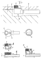
- Fig. 2 shows a fitting 1a, which extends from the fitting 1 Fig. 1 differs in that a bore 2a is arranged obliquely in a part 61b of the fitting 1a.
- a connection 3a with an external thread is guided at a distance to a part of the fitting 1a, in which a rod 5a of an adjusting device is mounted. The distance is necessary so that the external thread can be used.
- FIG. 3 shown fitting 1b differs from the fitting 1a according to Fig. 2 in particular in that a part 61b, which with a slightly further projecting external thread 3b than the external thread 3a according to Fig. 2 is not screwed into the part 60b, but is plugged.
- two circumferential sealing rings 16b are arranged on the outer surface of the part 61b.
- the part 61b is secured by a snap ring 10 provided for engagement in a groove of the part 60b, on which two tabs 11 are formed.
- the tabs 11 are each provided with a thread into which 10 screws 12 are screwed for fixing the part 61b in its position on the snap ring.
- the part 61b is rotatable, and the terminal 3b arranged eccentrically in the direction of the axis of the part 61b changes its position horizontally and vertically.
- the position of the terminal 3b can be adjusted if e.g. Cold and hot water connections are arranged at different heights, adjust and adapt to a device.
- a fitting 1c after Fig. 4 is similar to the embodiments of the Fig. 1 . 2 and 3 constructed, but the fitting 1c is formed from a single part.
- a plate 4c can be introduced into the fitting 1c, an opening is provided on the back, in which a plug 13 can be screwed.
- the shutter blade 4c is brought into its closed or open position by means of a rod 5c formed on it.
- a compression spring 14 is arranged between the plug 13 and the plate 4c.
- the closure plate 4c can be pushed to the end of a nipple 15 by a sealing surface 16c, to which it normally rests.
- the closure plate 4c can be brought more easily in the closed or in the open position. In addition, it dissolves better from the sealing surface 16c, if it has not been moved for a long time and adheres to the seal 16c.
- the compression spring 14c then presses it again against the sealing surface 16c.
- a space 17 for the pivoting of the closure plate 4c is arranged offset to an axis of the thread 3c and the passage 2c arranged correspondingly more centric to the threaded connection 3c.
- Fig. 4c shows the plate 4c in the open position, in which it releases the passage 2c.
- a fitting 1m in which a means for adjusting a flow through the fitting 1m is achieved with a disc 4m, in which a semicircular recess 57 is provided and which is provided to a little more than half of its circumference with a ring gear 56.
- the sealing washer 4m is arranged between a part 61 m of the fitting 1m and a sealing washer 17m. The part of the circumference of the sealing disc 4m not provided with the toothed rim 56 is supported on an inner wall of the part 61m of the fitting 1m.
- the sealing disk 4m is moved by means of a shaft 5m provided with teeth 58 on the side facing the sealing disk 4m by the shaft 5m being rotated and the teeth 58 engaging in the ring gear 56.
- the shaft 5m is provided on its in the direction of a thread 3m projecting side with a recess 55 for a screwdriver.
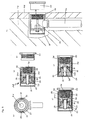
- Fig. 5 1d shows a fitting 1d with a 1/2 "fitting connection thread 3d and a passage 2d centrally arranged behind it in an intermediate wall 1.
- the fitting 1d is provided with a protective sleeve 24 which protects the sliding mechanism from plaster or tile mortar.
- the passage 2d is closed with a sealing washer 18, which is held in a closed position by a pressure spring 14d which is repelled by its other end against a holder 19 for the sealing washer 18.
- the sealing disc 18 is connected to a rod 5 d, which is sealingly guided through a recess of the holder 19.
- the holder 19 can be screwed with an external thread into an internal thread of a part 61d of the fitting 1d.
- a U-shaped means 20 for displacing the holder 19 is arranged, the legs of which are guided in grooves provided on the outer circumference of the fitting 1e.
- a thread 22 is inserted on the outer circumference of the part 61 d, which serves to receive a knurled nut 23.
- the knurled nut 23 is in the in Fig. 5e shown closed position to the ends of the legs of the device 20d screwed onto the thread 22.
- the knurled nut 23a is further rotated on the thread 22 and by means of the device 20d, which is then pushed back, the rod 5d and with it the sealing disc 18 is pulled away from the passage 2d.
- the passage 2d is then as in Fig. 5d shown, opened.
- the compression spring 14d is compressed.
- Fig. 5f shows the fitting 1d with a supply line 6d installed behind a plaster and tile 8d in a masonry 7d and the knurled nut 23d in a position before it is screwed onto the thread 3d.
- the fitting 1d compared to the previous embodiments, no enlarged in diameter pivotal space required.
- the fitting 1d has approximately the same external dimensions as a commercially available fitting.
- Fig. 6 shows a fitting 1e with a thread 3e and behind provided in an intermediate wall passages 2e.
- a sealing disc 16e made of ceramic is mounted, which has two passages 2e in the same arrangement as the intermediate wall.
- the passages 2e have the shape of triangles, one leg of which is rounded and lie symmetrically in the disk surface.
- a further likewise made of ceramic sealing disc 25 is arranged, which has two oppositeêtnikausschnitte 26 which release in the open position, the passages 2e in the front sealing disc 16e. In the closed position, the passages in the front ceramic disc 16e are closed by the part of the rear sealing disc 25 which has no recesses.
- the rear sealing washer 25 is connected to a shaft 5e, which is sealed in a bore in a holder 19e.
- an adjusting device On the side facing away from the thread 3e of the shaft 5e, an adjusting device is arranged, which has a lever 27 which is angled and extends parallel to the outer circumference of the fitting 1e in the direction parallel to the thread 3e.
- a handle 28 is placed on this web 27, by means of which the web 27 and with it the sealing disk 25 is rotated by 90 °.
- Fig. 6b is sealing washer 25 in shown in its closed position in which it closes the passages 2e of the other sealing disc 16e.
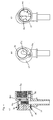
- Fig. 7 is a fitting 1f shown, in which the flow can be regulated in the manner of a ball valve.
- a ball 29 provided with a bore 32 is disposed between sealing rings 30, which is connected to a shaft 5f.
- the shaft 5f is sealed with sealing rings through a bore in the housing of the fitting 1f and connected to open or close the fitting 1f with a handle 31.
- the bore 32 in the ball 29 is half round and extends offset from the center of the ball 29. Due to this arrangement, it is sufficient to rotate the ball 29 by about 45 ° to bring them from the closed to the open position and vice versa. Correspondingly small is also to be carried out with the shaft 5f and or the handle bar 31 movement.
- the space which is provided for the fitting 1f in the connection region of a wall 7f or of tiles 8f is sufficient to carry out the movement necessary for opening and closing the fitting 1f with the gripping strip 31 or with an extension 33 which can be plugged thereon.
- FIG. 8 the flow with a ball 29g regulating fitting 1g, the ball 29g of a running through the center of the ball 29g bore 32g is provided.
- a shaft 5g connected to the ball 29g is located immediately below the thread 3g and parallel to it in a bore in the housing of the fitting 1g. In order to enable actuation of the shaft 5g, it is provided with a recess for engagement of a Allen wrench 9g.
- a plug 42 Above the ball 29g, a plug 42 is arranged, are pressed with the sealing rings 30g to the ball. Below a thread 41 of the plug 42, in which this is screwed onto the fitting 1g, passages 50 are inserted, can pass through the transportable gas or water into a passage 2g.
- Fig. 8a is the ball 29g in its closed position, in which the bore 32g perpendicular and in Fig. 8b shown in their open position.
- Fig. 9 shows a one-piece fitting 1h, in which a means for adjusting the flow through the fitting 1h has a cylindrical body 34.
- the cylinder 34 is provided with an angled bore 37, which is partially guided along the axis of the cylinder and partly perpendicular thereto.
- the seal between the bore 37 and the passage opening 38 is achieved by a sealing ring 39 which is arranged in a circumferential groove around the bore 37.
- a projection 5h is formed on the cylinder 34, to which an adjusting device 27h attacks.
- the adjusting device 27h is angled outwardly within a housing 24h parallel to the axis of the cylinder 34 in the direction of the thread 3h.
- FIGS. 9b and 9c is apparent by pivoting the adjusting device 27h of the in Fig. 9b shown position in the Fig.
- Fig. 10 is a like the fitting 1h constructed fitting 1j in a masonry 7j and arranged under plaster or tile 8j and connected to a supply line 6j.
- An extension 44 of the adjusting device 27j guided in a housing 24j of the fitting 1j is provided, which is inserted onto an angled end of the adjusting device 27 projecting from the masonry 7j.
- the extension 44 is displaceable and, if the plaster has been applied eg too thick, can be adjusted accordingly.
- the extension 44 can protrude so little perpendicularly from the fitting 1h that a cover rosette 51 covering the fitting 1h on the plaster or the tiles 8j also engages over the extension 44.
- an extension 52 for the adjusting device 27 is provided.
- the extension 52 is placed on the extension 44 and then withdrawn again. If the covering rosette 51 is fully seated, the extension web is arranged below the covering rosette 51. If you want to repair or replace a mixer connected to the fitting 1j, you do not have to shut off the water supply to the whole apartment or the bathroom, but you must shut off the cold and hot water supply of the mixer by means of the fitting 1h.
- the rosette is unscrewed from the wall or pulled, the extension 52 put on the other extension 44 and the fitting 1j opened with the extension 52 or closed.
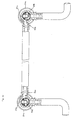
- Fig. 11 shows a one-piece Einrohran gleichgarnitur 41, which is used for valve radiator with a lower port.
- the connection fitting 41 has two fittings VL, RL, to which the inlet and outlet connections of a radiator is connected.
- the fittings 1k are constructed similar to the fittings 1h according to the embodiment according to Fig. 9 but are axially provided with a second passage 45 through which the two fittings VL, RL are connected by a connecting pipe 46.
- the fittings VL, RL are provided with a cylinder 47 as a closure body having a bore corresponding to the cylinder 34 in accordance with Fig. 9 is angled and partially axially and partially radially.
- bore 48 also extending radially and perpendicular to bore 37k, which coincides with the axial portion of the bore at the same location as the radial portion of bore 37k.
- holes 37k and 48 are guided sealing rings.
- levers 27k are provided, with which the fittings 1k can be adjusted, as it was already for Fig. 9 is described.
- Fig. 11b shows the Einrohran gleichgarnitur 41 in a position of the fittings 1k, in which the in Fig. 11b not shown, the radiator-facing terminals, the water is passed through the passage 45.
- the radiator is thus completely separated from the water cycle and can, for example, for repair, be removed without it being necessary to block the entire water cycle.
- the other series-connected radiator can continue to operate.
- a common housing 50 is provided for the two fittings RL, VL.
- Fig. 12 a Einrohran gleichgarnitur is shown, which is used for radiators, in which the supply and the return port are arranged at a greater distance from each other.
- the two fittings are not formed in one piece, but are connected by an additional pipe. Accordingly, additional ports 54a and 54b are provided for the pipe.
Landscapes
- Health & Medical Sciences (AREA)
- Life Sciences & Earth Sciences (AREA)
- Engineering & Computer Science (AREA)
- Hydrology & Water Resources (AREA)
- Public Health (AREA)
- Water Supply & Treatment (AREA)
- Quick-Acting Or Multi-Walled Pipe Joints (AREA)
Applications Claiming Priority (2)
| Application Number | Priority Date | Filing Date | Title |
|---|---|---|---|
| DE200820009640 DE202008009640U1 (de) | 2008-07-16 | 2008-07-16 | Sanitärer Armaturenanschluss |
| DE202009003623 | 2009-03-12 |
Publications (1)
| Publication Number | Publication Date |
|---|---|
| EP2146010A1 true EP2146010A1 (fr) | 2010-01-20 |
Family
ID=41259095
Family Applications (1)
| Application Number | Title | Priority Date | Filing Date |
|---|---|---|---|
| EP09009270A Withdrawn EP2146010A1 (fr) | 2008-07-16 | 2009-07-16 | Raccord |
Country Status (1)
| Country | Link |
|---|---|
| EP (1) | EP2146010A1 (fr) |
Cited By (2)
| Publication number | Priority date | Publication date | Assignee | Title |
|---|---|---|---|---|
| DE202011102163U1 (de) | 2011-06-22 | 2011-10-25 | Norbert Scherer | Armaturenanschluss |
| WO2012068415A3 (fr) * | 2010-11-18 | 2012-11-01 | Rod Gibson | Évier encastré |
Citations (3)
| Publication number | Priority date | Publication date | Assignee | Title |
|---|---|---|---|---|
| GB2219065A (en) | 1988-04-23 | 1989-11-29 | Rothwell Shower Products Ltd | Pipe valves |
| US6832396B1 (en) | 2003-08-01 | 2004-12-21 | Globe Union Industrial Corp. | Back-to-back bathroom tap control valve |
| WO2007105966A1 (fr) | 2006-03-14 | 2007-09-20 | Isotec Limited | Raccord de tuyauterie |
-
2009
- 2009-07-16 EP EP09009270A patent/EP2146010A1/fr not_active Withdrawn
Patent Citations (3)
| Publication number | Priority date | Publication date | Assignee | Title |
|---|---|---|---|---|
| GB2219065A (en) | 1988-04-23 | 1989-11-29 | Rothwell Shower Products Ltd | Pipe valves |
| US6832396B1 (en) | 2003-08-01 | 2004-12-21 | Globe Union Industrial Corp. | Back-to-back bathroom tap control valve |
| WO2007105966A1 (fr) | 2006-03-14 | 2007-09-20 | Isotec Limited | Raccord de tuyauterie |
Cited By (9)
| Publication number | Priority date | Publication date | Assignee | Title |
|---|---|---|---|---|
| WO2012068415A3 (fr) * | 2010-11-18 | 2012-11-01 | Rod Gibson | Évier encastré |
| US9157219B2 (en) | 2010-11-18 | 2015-10-13 | Rod Gibson | Undermount sink |
| US10221547B2 (en) | 2010-11-18 | 2019-03-05 | Rod Gibson | Undermount sink |
| US10870973B2 (en) | 2010-11-18 | 2020-12-22 | Rod Gibson | Undermount sink |
| US11384518B2 (en) | 2010-11-18 | 2022-07-12 | Rod Gibson | Undermount sink |
| US11739510B2 (en) | 2010-11-18 | 2023-08-29 | Rod Gibson | Undermount sink |
| US12338611B2 (en) | 2010-11-18 | 2025-06-24 | Rod Gibson | Undermount sink |
| DE202011102163U1 (de) | 2011-06-22 | 2011-10-25 | Norbert Scherer | Armaturenanschluss |
| DE102012012590A1 (de) | 2011-06-22 | 2012-12-27 | Norbert Scherer | Armaturenanschluss |
Similar Documents
| Publication | Publication Date | Title |
|---|---|---|
| EP0389814A1 (fr) | Dispositif de raccordement pour robinets mélangeurs | |
| DE19603398B4 (de) | Heizungsanschlussvorrichtung, Verteiler und Bauelement für Heizungen | |
| DE202014006320U1 (de) | Anschlussvorrichtung und sanitäre Anlage | |
| DE202008006949U1 (de) | Sanitär-Eckventil zum Anschluss von Waschtischarmaturen | |
| AT396605B (de) | Unterputzanschlussstück für sanitärarmaturen | |
| EP0876564A1 (fr) | Raccord de tuyaux | |
| EP1760205B1 (fr) | Boîte de raccordement pour une armature sanitaire et système des armatures sanitaires. | |
| DE19529189A1 (de) | Anschlußstück | |
| EP1484544B1 (fr) | Traversée de conduite pour l'installation d'un tube sanitaire à travers un mur | |
| DE60006546T2 (de) | Anschluss für einen wasserzähler | |
| EP0538196A1 (fr) | Dispositif pour le raccordement d'un tuyau flexible sous le crépi d'un mur et d'une robinetterie sur le crépi d'un mur | |
| DE202010013842U1 (de) | Fitting | |
| DE19854848B4 (de) | Anschlusseinrichtung für Heizkörper | |
| EP0309397A1 (fr) | Dispositif pour raccordement en eau d'installations sanitaires | |
| EP1435480B1 (fr) | Robinetterie sanitaire | |
| EP1606545B1 (fr) | Prise destinee au gaz | |
| DE10151995C1 (de) | Gassteckdose | |
| AT521523B1 (de) | Anschlussarmatur zur Steuerung der Flussrichtung eines Heizungsmediums in einem Heizkörper | |
| DE29512786U1 (de) | Anschlußstück | |
| EP2180101A1 (fr) | Armature encastrée sanitaire | |
| CH692514A5 (de) | Vorrichtung zur dichtenden Einführung eines Rohres in ein Gebäude. | |
| CH695704A5 (de) | Armatur insbesondere zur Verwendung als Verteiler in einem Leitungssystem. | |
| DE20221870U1 (de) | Wasserzapfarmatur mit Schlauchbrause | |
| DE20104615U1 (de) | Baugruppe für ein Heizungssystem | |
| DE202008009640U1 (de) | Sanitärer Armaturenanschluss |
Legal Events
| Date | Code | Title | Description |
|---|---|---|---|
| PUAI | Public reference made under article 153(3) epc to a published international application that has entered the european phase |
Free format text: ORIGINAL CODE: 0009012 |
|
| AK | Designated contracting states |
Kind code of ref document: A1 Designated state(s): AT BE BG CH CY CZ DE DK EE ES FI FR GB GR HR HU IE IS IT LI LT LU LV MC MK MT NL NO PL PT RO SE SI SK SM TR |
|
| AX | Request for extension of the european patent |
Extension state: AL BA RS |
|
| 17P | Request for examination filed |
Effective date: 20101110 |
|
| 17Q | First examination report despatched |
Effective date: 20110125 |
|
| STAA | Information on the status of an ep patent application or granted ep patent |
Free format text: STATUS: THE APPLICATION IS DEEMED TO BE WITHDRAWN |
|
| 18D | Application deemed to be withdrawn |
Effective date: 20150203 |