EP2146019A1 - Leichte Tragstrukturen, die mit Kernelementen aus Segmenten bewehrt sind, sowie Gussverfahren für derartige Strukturen - Google Patents
Leichte Tragstrukturen, die mit Kernelementen aus Segmenten bewehrt sind, sowie Gussverfahren für derartige Strukturen Download PDFInfo
- Publication number
- EP2146019A1 EP2146019A1 EP08160304A EP08160304A EP2146019A1 EP 2146019 A1 EP2146019 A1 EP 2146019A1 EP 08160304 A EP08160304 A EP 08160304A EP 08160304 A EP08160304 A EP 08160304A EP 2146019 A1 EP2146019 A1 EP 2146019A1
- Authority
- EP
- European Patent Office
- Prior art keywords
- core
- elements
- segments
- light
- prestressing
- Prior art date
- Legal status (The legal status is an assumption and is not a legal conclusion. Google has not performed a legal analysis and makes no representation as to the accuracy of the status listed.)
- Withdrawn
Links
- 238000000034 method Methods 0.000 title claims abstract description 16
- 238000005266 casting Methods 0.000 title claims abstract description 13
- 238000007906 compression Methods 0.000 claims abstract description 70
- 230000006835 compression Effects 0.000 claims abstract description 70
- 239000000463 material Substances 0.000 claims abstract description 62
- 239000011440 grout Substances 0.000 claims description 14
- 239000004567 concrete Substances 0.000 description 35
- 239000011372 high-strength concrete Substances 0.000 description 17
- 230000002787 reinforcement Effects 0.000 description 12
- 229910000831 Steel Inorganic materials 0.000 description 8
- 239000010959 steel Substances 0.000 description 8
- 239000000835 fiber Substances 0.000 description 6
- 238000005304 joining Methods 0.000 description 6
- 238000004901 spalling Methods 0.000 description 6
- 239000000919 ceramic Substances 0.000 description 5
- 238000010276 construction Methods 0.000 description 5
- 230000007797 corrosion Effects 0.000 description 5
- 238000005260 corrosion Methods 0.000 description 5
- 239000007779 soft material Substances 0.000 description 5
- OKTJSMMVPCPJKN-UHFFFAOYSA-N Carbon Chemical compound [C] OKTJSMMVPCPJKN-UHFFFAOYSA-N 0.000 description 4
- 229910052799 carbon Inorganic materials 0.000 description 4
- 239000011521 glass Substances 0.000 description 4
- 239000011513 prestressed concrete Substances 0.000 description 4
- 239000011150 reinforced concrete Substances 0.000 description 4
- 239000004570 mortar (masonry) Substances 0.000 description 3
- 239000004033 plastic Substances 0.000 description 3
- 239000000565 sealant Substances 0.000 description 3
- 239000004593 Epoxy Substances 0.000 description 2
- 241001465754 Metazoa Species 0.000 description 2
- 239000004743 Polypropylene Substances 0.000 description 2
- 239000000654 additive Substances 0.000 description 2
- 238000005452 bending Methods 0.000 description 2
- 230000009286 beneficial effect Effects 0.000 description 2
- 239000011449 brick Substances 0.000 description 2
- 239000003086 colorant Substances 0.000 description 2
- 238000005336 cracking Methods 0.000 description 2
- 238000005516 engineering process Methods 0.000 description 2
- 239000002360 explosive Substances 0.000 description 2
- 239000004744 fabric Substances 0.000 description 2
- 239000002184 metal Substances 0.000 description 2
- 229910052751 metal Inorganic materials 0.000 description 2
- 150000002739 metals Chemical class 0.000 description 2
- -1 polypropylene Polymers 0.000 description 2
- 229920001155 polypropylene Polymers 0.000 description 2
- 229910052573 porcelain Inorganic materials 0.000 description 2
- 238000007789 sealing Methods 0.000 description 2
- 230000003068 static effect Effects 0.000 description 2
- 229910052572 stoneware Inorganic materials 0.000 description 2
- 210000002105 tongue Anatomy 0.000 description 2
- 229910001294 Reinforcing steel Inorganic materials 0.000 description 1
- 230000015572 biosynthetic process Effects 0.000 description 1
- 239000002131 composite material Substances 0.000 description 1
- 239000012141 concentrate Substances 0.000 description 1
- 238000006073 displacement reaction Methods 0.000 description 1
- 238000009826 distribution Methods 0.000 description 1
- 230000000694 effects Effects 0.000 description 1
- 238000009432 framing Methods 0.000 description 1
- 238000003780 insertion Methods 0.000 description 1
- 230000037431 insertion Effects 0.000 description 1
- 230000003993 interaction Effects 0.000 description 1
- 230000001788 irregular Effects 0.000 description 1
- 239000000314 lubricant Substances 0.000 description 1
- 238000004519 manufacturing process Methods 0.000 description 1
- 210000003205 muscle Anatomy 0.000 description 1
- 239000002245 particle Substances 0.000 description 1
- 238000003825 pressing Methods 0.000 description 1
- 230000003014 reinforcing effect Effects 0.000 description 1
- 230000009528 severe injury Effects 0.000 description 1
- 238000007493 shaping process Methods 0.000 description 1
- 230000003019 stabilising effect Effects 0.000 description 1
- 230000000087 stabilizing effect Effects 0.000 description 1
- 210000002435 tendon Anatomy 0.000 description 1
- 238000009431 timber framing Methods 0.000 description 1
- 230000007704 transition Effects 0.000 description 1
- XLYOFNOQVPJJNP-UHFFFAOYSA-N water Substances O XLYOFNOQVPJJNP-UHFFFAOYSA-N 0.000 description 1
Images

Classifications
-
- E—FIXED CONSTRUCTIONS
- E04—BUILDING
- E04C—STRUCTURAL ELEMENTS; BUILDING MATERIALS
- E04C3/00—Structural elongated elements designed for load-supporting
- E04C3/02—Joists; Girders, trusses, or trusslike structures, e.g. prefabricated; Lintels; Transoms; Braces
- E04C3/20—Joists; Girders, trusses, or trusslike structures, e.g. prefabricated; Lintels; Transoms; Braces of concrete or other stone-like material, e.g. with reinforcements or tensioning members
- E04C3/26—Joists; Girders, trusses, or trusslike structures, e.g. prefabricated; Lintels; Transoms; Braces of concrete or other stone-like material, e.g. with reinforcements or tensioning members prestressed
-
- E—FIXED CONSTRUCTIONS
- E04—BUILDING
- E04C—STRUCTURAL ELEMENTS; BUILDING MATERIALS
- E04C2/00—Building elements of relatively thin form for the construction of parts of buildings, e.g. sheet materials, slabs, or panels
- E04C2/02—Building elements of relatively thin form for the construction of parts of buildings, e.g. sheet materials, slabs, or panels characterised by specified materials
- E04C2/10—Building elements of relatively thin form for the construction of parts of buildings, e.g. sheet materials, slabs, or panels characterised by specified materials of wood, fibres, chips, vegetable stems, or the like; of plastics; of foamed products
- E04C2/20—Building elements of relatively thin form for the construction of parts of buildings, e.g. sheet materials, slabs, or panels characterised by specified materials of wood, fibres, chips, vegetable stems, or the like; of plastics; of foamed products of plastics
- E04C2/22—Building elements of relatively thin form for the construction of parts of buildings, e.g. sheet materials, slabs, or panels characterised by specified materials of wood, fibres, chips, vegetable stems, or the like; of plastics; of foamed products of plastics reinforced
-
- E—FIXED CONSTRUCTIONS
- E04—BUILDING
- E04C—STRUCTURAL ELEMENTS; BUILDING MATERIALS
- E04C2/00—Building elements of relatively thin form for the construction of parts of buildings, e.g. sheet materials, slabs, or panels
- E04C2/02—Building elements of relatively thin form for the construction of parts of buildings, e.g. sheet materials, slabs, or panels characterised by specified materials
- E04C2/26—Building elements of relatively thin form for the construction of parts of buildings, e.g. sheet materials, slabs, or panels characterised by specified materials composed of materials covered by two or more of groups E04C2/04, E04C2/08, E04C2/10 or of materials covered by one of these groups with a material not specified in one of the groups
-
- E—FIXED CONSTRUCTIONS
- E04—BUILDING
- E04C—STRUCTURAL ELEMENTS; BUILDING MATERIALS
- E04C3/00—Structural elongated elements designed for load-supporting
- E04C3/02—Joists; Girders, trusses, or trusslike structures, e.g. prefabricated; Lintels; Transoms; Braces
- E04C3/20—Joists; Girders, trusses, or trusslike structures, e.g. prefabricated; Lintels; Transoms; Braces of concrete or other stone-like material, e.g. with reinforcements or tensioning members
- E04C3/22—Joists; Girders, trusses, or trusslike structures, e.g. prefabricated; Lintels; Transoms; Braces of concrete or other stone-like material, e.g. with reinforcements or tensioning members built-up by elements jointed in line
Definitions
- the invention relates to light-weight load-bearing structures reinforced by core elements with a core of a strong material constituting one or more compression or tension zones in the structure to be cast, which core is surrounded by or adjacent to a material of less strength compared to the core.
- the invention further relates to a method of casting of light-weight load-bearing structures reinforced by core elements of a strong material constituting one or more compression or tension zones in the structure to be cast, which core is surrounded by or adjacent to a material of less strength compared to the core.
- One well-known method is to reinforce concrete by applying rods, wires or profiles of steel to take tension and shear in reinforced concrete structures.
- Another method is to combine straight hot rolled steel profiles and heavy concrete into composite structures or to make "sandwich slabs" with steel reinforcement bars or grids in the tension layers or with steel plates as tension or compression layers.
- a compressed cross section such as a column or pillar of a strong material like high-strength concrete will have a tendency to deflect or buckle to the sides when pressure is applied to the ends of the pillar, unless the cross section of the pillar is rather large.
- Prestressed concrete structures are applied to for example TT beams for large spans in prefabricated halls for industry and commerce. These beams represent a quite optimal use of heavy reinforced concrete.
- Super Light Structures with concentrated compression and tension zones embedded in light material may improve the performance considerably with regard to dimensioning the structure and the length of the free span of the load-bearing structure.
- the path of the prestressing cables may follow the variation of the moment load.
- the tension zone is optimized, but the compression zone is not.
- the entire cross-section is compressed and not cracked, and it therefore contributes to the stiffness counteracting deflections.
- the compression zone is stabilizing itself.
- the stability is provided by a light material in contact with or surrounding the compression zone and further the compression zone is build up as a core element consisting of segments of a material of suitable compressive strength such as a high-strength concrete protected by the light material.
- the segments of core elements should be made of a strong material.
- a suitable material could be extruded high-strength concrete with or without fibre reinforcement for improving the ductility, ordinary concrete, or ceramics, but any other materials can be used as long as the strength is sufficient, and they have sufficient other properties needed for their function in the actual structure.
- carbon-fibre based materials may be an option for core segments leading to even lighter structures.
- the reason for making prestressed concrete structures is mainly to reduce deflections. This is usually done by providing the structure with prestressed reinforcement as wires or rods, which act with a compression force on the entire concrete cross-section. When the section is subjected to bending, compression is introduced in one side and tension in the opposite. Tension from the bending moment unloads the compression from the pre-stressing instead of giving rise to tensile stresses and formation of cracks in the tension zone, as would happen in a slack reinforced concrete structure. The cross-section is therefore not reduced by cracking and will preserve its maximum flexural stiffness reducing the deflections from variable load.
- the prestressing reinforcement can be arranged in a path, where the prestressing force will give rise to a deflection opposite the deflection of the structure for its dead loads, and therefore result in no deflection at all.
- the invention further provides a new simple possibility of establishing compression zones for super-light structures by applying for example prefabricated pieces of strong material which are prestressed before casting soft material around or adjacent to it.
- the invention makes it possible to cast a super-light load-bearing structure with an optimized shape of the compression zone by providing compression arches or prestressed tension zones formed by segments of core elements to be cast into, and interact with a light material.
- Such core elements can be formed in segments of different shapes and in different lengths.
- the invention is intended to cover all aspects of shaping the segments of core elements falling between the embodiments mentioned above in such a way that some segments of core elements can be of different shape and/or length and at the same time some of the other segments of core elements can have same shape and/or same length.
- Segments are referred to in the description as segments of core elements, which segments can be of any suitable size and shape and to be used according to the invention.
- a load-bearing structure as a strong skeleton included in a soft material, where the skeleton is constructed from segments of core elements of suitable compressive strength such as strong concrete, ceramics or high-strength concrete with or without a fibre reinforcement and applied as one or more compression zones or tension zones. Segments of core elements are provided along one or more compression or tension zones, in a structure to be cast, surrounded partly or fully by concrete of less strength compared to that of the cores.
- a core constructed from segments of core elements is intended to be a compression zone, the prestressing is assessed to be the smallest possible for the core to be stable and self-supporting, until it is cast into a super-light structure, where it can be loaded in compression.
- a core constructed from segments of core elements is intended to be a tension zone, the prestressing is assessed to be sufficiently large for the maximum tension force to be counteracted by unloaded compression of the core segments.
- the segments of core elements can include one or more reinforcement zones in form of one or more bores, holes, or grooves running through the segments of core elements.
- the bores, holes, or grooves are in the following referred to as holes since any kind of a channel or the like running inside or along a segment of core element can be used as guide for a prestressing element.
- the hole or holes for the prestressing element or elements runs substantially parallel to the outer surface of the segment of core elements.
- segments of core elements When assembling elements to a certain shape it is possible to use segments of core elements with different numbers of holes. This can be possible for example if one or more segments of core elements are provided with means for joining the prestressing elements within or adjacent to the core element.
- a light-weight load-bearing structure reinforced by core elements with a core of a strong material constituting one or more compression or tension zones in the structure to be cast, which core is surrounded by or adjacent to a material of less strength compared to the core, where the core is constructed from segments of core elements assembled by means of one or more prestressing elements.
- one or more segments of a core element has at least one plane end at substantially 90 degrees relative to a longitudinal axis going through the core elements
- this is done by one or more segments of a core element being a curved segment.
- one or more segments of a core element is provided with one or more holes for guiding one or more prestressing elements.
- the hole or holes for the prestressing element or elements runs substantially parallel to the outer surface of the segment of core elements.
- the core element can be provided with a number of openings on the side of the core element for connection to ends of other segments of core elements and thereby forms a kind of knot segment.
- a segment of a core element forming a knot segment is formed as a "Y" or a cross with a number of arms protruding from the body of the core element, or a number of faces, each arm or face designed for connection to an end surface of a segment of a core element or the connection of another knot segment.
- the one or more holes for guiding one or more prestressing elements are provided with a lining.
- the one or more holes with or without a lining for guiding one or more prestressing elements are filled with grout.
- the grout can act as a kind of lubricant during insertion of the prestressing element and when hardened the grout will cause a sealing of the holes further providing a heat and corrosion protection of the prestressing element in addition to the heat and corrosion protection provided of the joined segments of core elements covered by concrete of less strength compared to that of the core elements
- the one or more holes for guiding one or more prestressing elements are provided with retaining means for retaining the one or more prestressing element in prestressed condition
- Such retaining means can be any known retaining means such as wedges, nuts or the like.
- the core is constructed from segments of core elements assembled and held together by means of one or more prestressing elements.
- tension is applied to the core elements by applying one or more prestressing elements through one or more holes in the core elements which one or more holes guides the one or more prestressing elements, the one or more holes are filled with grout before or during prestressing the one or more prestressing elements.
- tension is applied to the core elements by applying one or more prestressing elements through one or more holes in the core elements which one or more holes guides the one or more prestressing elements, the one or more holes are filled with grout after one or more prestressing elements are prestressed.
- scaffolding can even be reduced or avoided.
- the invention it is possible to form compression or tension zones from segments of core elements of strong concrete at a factory or at the construction site, where the larger load-bearing structure is to be produced.
- the strong concrete core member or members are placed in a mould or the mould is alternatively supported by the core, and thereafter the load-bearing structure is produced and cast out with light material whereby the strong concrete core member or members are completely or partly surrounded by light material.
- the invention makes it possible to give the structure an external shape supporting the applications or building structures, so that the load can be applied, and give a possibility for the structure to be included in for example roofs, walls, tunnels, bridges or any other structure.
- the invention makes it possible to protect the compression or tension zones against mechanical impacts.
- the invention makes it possible to protect the compression zones against fire. Fire is especially a problem for high-strength concrete, because the risk of explosive spalling and a number of severe damages have been seen due to spalling of structures made of high-strength concrete.
- the spalling is a major hindrance for the application of high-strength concrete.
- the invention may use ordinary porous concrete instead, but high-strength concrete will sometimes be beneficial, and the invention may solve the spalling problem for example by ensuring that the concrete is not heated above a limit near the critical temperature for water 374°C, where spalling problems occur. This can for example be achieved by having the high-strength concrete embedded in a light concrete of a light-weight load-bearing structure, where the light material provides a heat isolating effect to the core.
- fire proof materials of sufficiently high strength may be applied such as for example ceramics, brick, stoneware, porcelain, or porous concrete.
- This technology makes minimal structures more applicable for buildings.
- This technology makes high-strength concrete and other strong materials more applicable for buildings.
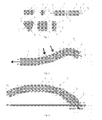
- the invention is derived rethinking a load-bearing structure as a strong skeleton included in a soft material, where the skeleton is constructed from segments 1 of core elements 2 of suitable compressive strength such as strong concrete, ceramics or high-strength concrete with or without a fibre reinforcement and applied as one or more compression zones or tension zones.
- Segments 1 of core elements 2 are provided along one or more compression or tension zones, in a structure to be cast, surrounded partly or fully by concrete of less strength compared to that of the cores.
- Segments 1 are referred to in the description as segments 1 of core elements 2, which segments 1 can be of any suitable size and shape and to be used.
- stability is provided by a light material in contact with or surrounding the compression zone and further the compression zone is build up as a core element 2 consisting of segments 1 of a material of suitable compressive strength such as a high-strength concrete protected by the light material.
- the segments 1 of core elements 2 can include one or more reinforcement zones in form of one or more bores, holes, or grooves 3 running through the segments 1 of core elements 2.
- the bores, holes, or grooves 3, are in the following referred to as holes 3 since any kind of a channel or the like running inside or along a segment 1 of a core 2 element can be used as guide for a prestressing element 4.
- the hole or holes 3 for the prestressing element or elements 4 runs substantially parallel to the outer surface of the segment 1 of a core element 2.
- each segment 1 of a core element 2 is designed and shaped in relation to the position in the structure where the segment 1 is to be positioned.
- the segments 1 of core elements 2 are formed as modular elements. Hereby it is possible to build up a structure of core elements 2 taken from a catalogue. In other words, it is possible to manufacture the segments 1 of core elements 2 in standardised shapes and lengths.
- the segments 1 of core elements 2 are combined in such a way that it is possible to construct core elements 2 with bends in two or three dimensions. This is achieved by using curved elements or by providing at least one end 5 of a core segment with a plane showing an angle different from 90 degrees to a longitudinal axis in the direction of a normal force acting between the core elements.
- core segments 1 having plane ends 5 at substantially 90 degrees with segments 1 having ends 5 formed with a plane sloping surface or by application of curved segments 1, it is possible to create core elements 2 extending in two or three dimensions.
- the length of the segments 1 of core elements 2 can be of standardised lengths, individual lengths, and lengths modified to the building structure.
- segments 1 of core elements 2 being curved or having sloping ends 5 in different angles. Thereby it is possible to combine for example two segments 1 of core elements 2 of 15 degrees and one segment 1 of a core element 2 of 20 degrees to apply a bend of 50 degrees to the core element 2.
- segments 1 of core elements 2 are provided with more than one hole 3, two adjacent segments 1 are not able to rotate relative to each other due to the number of prestressing elements 4 running through the holes 3.
- Such a locking member can be a hollow in form of a recess, groove or the like formed in one end of the segment 1 manufactured to interact with a corresponding elevation in the adjacent end of the segment 1 next in line or with a separate interlocking member in-between the two members when forming the skeleton of core elements 2.
- the segments 2 are prevented from rotation in axial direction in relation to each other, if this is needed.
- the position of the holes of two adjacent segments 1 may be secured to be in line.
- a layer of a kind of mortar, sealant or the like may be cast out between segments 1 of core elements 2 before prestressing.
- This mortar or sealant may compensate for irregular end-surfaces 5 of segments 1 to be joined.
- the mortar or sealant may in some cases fill out holes of adjacent segments 1 providing a lock.
- one or more compression zones with segments 1 of core elements 2 of for example strong concrete are combined with reinforcement in tension zones or with segments 1 of core elements 2 of for example strong concrete, where the core elements 2 takes tension by unloading prestressed compression.
- only the tension zones are formed as core elements 2 of prestressed segments 1, where the core elements 2 takes tension by unloading prestressed compression.
- segments 1 of core elements 2 can be provided by suitable parts such as ropes, wires, plates, meshes, fabrics, rods or bars of suitable materials such as steel, carbon fibres, glass, polypropylene fibres or products of plastic, metals or organic fibres.
- the holes 3 in the segments 1 of core elements 2, in which holes 3 the prestressing elements 4 are intended to be placed can be provided with a kind of lining (not shown) to reduce friction between the prestressing element 4 and segment 1. Especially when inserting and tensioning of the prestressing element 4 in the lining, the prestressing element 4 will slide through the holes 3 and at the same time undue forces acting during tensioning of the prestressing elements 4 are reduced or even prevented.
- Grouting is performed for example by injecting grout in the holes 3 of the core elements 2 so that the grout will surround the prestressing elements 4 positioned in the holes 3.
- the grout will then cause an attachment between the prestressing element 4 and the inner surface or an inner lining of the hole 3.
- the hardened grout will cause a sealing of the holes 3 further providing a heat and corrosion protection of the prestressing element 4 in addition to the heat and corrosion protection provided of the joined segments 1 of core elements 2 covered by concrete of less strength compared to that of the core elements 2
- a grout will also allow forces to be transferred between the prestressing element 4 and the segments 1 of core elements 2.
- unbonded tendons could be used.
- Another way to secure the segments 1 from displacement relative to each other and relative to the centre axis is to have a tube lining in one or more of the holes 3 in the segments 1 of core elements 2, which lining protrudes a distance out from the surface of one end portion of the segments 1.
- the lining is positioned a distance within the segment 1, which distance corresponds to the protruding distance of the lining from the preceding segment 1 of core elements 2.
- Such means can for example be corresponding grooves and tongues, or notches and ridges or half cylindrical shells protruding from the ends of the linings, together forming a tube, or corresponding shapes or cuts of the ends of lining tubes.
- segments 1 of core elements 2 with convex and/or concave end portions.
- the concave and convex end portions can be provided with grooves and/or tongues or ridges or intersecting elements.
- the grooves and/or ridges may be formed in concentric circles, or parts of concentric circles, or radial lines, or in any other suitable pattern.
- cross section variations can also be applied in order to counteract variations of load along a core element 2 for example due to the weight for the structure itself in an arch.
- more core elements 2 in compression, in tension or combinations of these are joined with or without application of special knot segments 6 to form a structure of more dimensions such as for example a shell, a hanging structure, a plate, a slab, a lattice, a girder, a tube, a box etc.
- the segments 1 of core elements 2 forming the knot segments can be formed as a "Y" or a cross with a number of arms protruding from the body of the core element 2, each arm designed for connection to an end surface 5 of a segment 1 of a core element 2 or the connection of another knot segment 6.
- Some segments 1 of core elements 2 can be provided with a number of openings (not shown) on the sides of the core element 2.
- the openings are designed for connection to an end surface 5 of a segment 1 of a core element 2 and the sides near to the openings or an end surface 5 of a core element 2 are adapted to be connected to each other either by providing a plane surface on the side close to the openings, by having plane sides in connection to the openings or by having curved ends 5 on the joining segments 1 of core elements 2.
- one or more compression or tension zones are provided with a cross section, which cross section increases towards points where forces are exchanged with other compression or tension zones.
- one or more compression zones formed by segments 1 of core elements 2 are provided with a cross section increasing towards at least one end 5.
- the increased cross sections of the compression or tension zones formed by segments 1 of core elements 2, for example at the ends 5, are joined in joints or by joining segments 1.
- a core element 2 formed by segments 1 of core elements 2 can be placed in a mould for a load-bearing structure, or in some embodiments a self supporting core element 2 may support a mould around or adjacent to it.
- a core element 2 formed by segments 1 of core elements 2 can be placed where it is desired to concentrate compression, for example in a compression arch.
- a core of segments 1 of core elements 2 of a strong material for example a strong concrete or a self-compacting high-strength concrete, is formed corresponding to the compression or tension zone in a building structure. Then a mould is thereafter cast out around the core with a light material, which for example can be light aggregate concrete.
- a strong material for example a strong concrete or a self-compacting high-strength concrete
- Strong concrete is any concrete stronger than the light material and it can be obtained in several different ways and the invention is not limited to a single method of obtaining strong concrete.
- a concrete of high strength may be applied, and it could be obtained by adding fine-grained particles to the concrete.
- additives to the strong concrete and/or to the light material among which super-plastifying additives, fibres of steel plastic or any other material, or materials may be used to obtain high-strength properties and/or improved workability such as self-compacting properties or ductility.
- Segments 1 of core elements 2 can also be made of any other material with sufficient strength and material properties required for the actual construction, which in some cases might be for example glass or carbon fibre reinforced epoxy, ceramics, brick, stoneware, porcelain, structural glass, steel etc.
- compression or tension zones By forming compression or tension zones from segments 1 of core elements 2, it is possible to give the compression or tension zones optimal shapes and layouts following the actual shape of force trajectories, and by applying prestressing elements 4 it is possible to further stabilise compression and tension zones for deflection and buckling prior to casting, so that they do not need to be stabilised in the mould or to be larger than necessary for the cross section to resist the load without being increased in order to ensure the flexural stiffness.
- scaffolding By means of self-supporting core elements 2, scaffolding can even be reduced or avoided.
- Stability of the core elements 2 is further achieved by the invention by a method of casting of lightweight load-bearing structures with an optimized compression zone where the core is constructed from segments 1 of core elements 2 and stabilised by a light material such as a lightweight concrete.
- the compression or tension zones represented by the cores 2 of strong materials can be provided with a larger cross section at the points joining other compression or tension zones or establishing joints or segments.
- Such elements can be ropes, wires, plates, meshes, fibres, fabrics, rods or bars of suitable materials such as steel, glass, carbon fibres, polypropylene fibres, or products of plastic, metals or organic fibres.
- the core elements 2 are cast out in such a way that they are visible from the outside through or at the surface of the material of less strength compared to the core 2, which material surrounds or is adjacent to the core 2. It is possible to achieve a kind of visible framing looking a bit like a "timber framing", thereby be able to provide visible arches in colours (for example shades of red, brown or black) in the building structure, and the adjacent stabilising material of less strength compared to the core 2 can be in the colours of for example shades of white, grey or light brown. Hereby it is possible to follow the static behaviour and the static construction in the building structure.
- a tensioning member within or along the "spine” may prevent the segments of the spine to deflect and it may enable it to take tension as unloaded compression without separating the segments of the spine.
Landscapes
- Engineering & Computer Science (AREA)
- Architecture (AREA)
- Civil Engineering (AREA)
- Structural Engineering (AREA)
- Life Sciences & Earth Sciences (AREA)
- Wood Science & Technology (AREA)
- Rod-Shaped Construction Members (AREA)
- Bridges Or Land Bridges (AREA)
- Manufacturing Of Tubular Articles Or Embedded Moulded Articles (AREA)
- Shafts, Cranks, Connecting Bars, And Related Bearings (AREA)
- Laminated Bodies (AREA)
- Rolling Contact Bearings (AREA)
- Moulding By Coating Moulds (AREA)
Priority Applications (15)
| Application Number | Priority Date | Filing Date | Title |
|---|---|---|---|
| EP08160304A EP2146019A1 (de) | 2008-07-14 | 2008-07-14 | Leichte Tragstrukturen, die mit Kernelementen aus Segmenten bewehrt sind, sowie Gussverfahren für derartige Strukturen |
| AT09709238T ATE532917T1 (de) | 2008-07-14 | 2009-03-13 | Durch aus segmenten bestehende kernelemente verstärkte leichte, lasttragende strukturen |
| EA201170185A EA018421B1 (ru) | 2008-07-14 | 2009-03-13 | Легкие несущие конструкции, армированные элементами сердечника, выполненными из сегментов, и способ бетонирования таких конструкций |
| PL09709238T PL2307631T3 (pl) | 2008-07-14 | 2009-03-13 | Lekkie konstrukcje nośne wzmocnione elementami rdzeniowymi wykonanymi z segmentów |
| JP2011517823A JP5595393B2 (ja) | 2008-07-14 | 2009-03-13 | セグメントから作られる芯材によって強化された軽量負荷支持構造 |
| PT09709238T PT2307631E (pt) | 2008-07-14 | 2009-03-13 | Estruturas de sustentação de carga leve reforçadas por elementos de núcleo constituídos por segmentos |
| CN200980127611XA CN102099536B (zh) | 2008-07-14 | 2009-03-13 | 通过由多个段制成的芯元件而被强化的轻重量的承载结构 |
| BRPI0916422A BRPI0916422A2 (pt) | 2008-07-14 | 2009-03-13 | estrutura de sustentação de carga leve, e, método de moldagem de estruturas de sustentação de cargas leves |
| EP09709238A EP2307631B1 (de) | 2008-07-14 | 2009-03-13 | Durch aus segmenten bestehende kernelemente verstärkte leichte, lasttragende strukturen |
| ES09709238T ES2377180T3 (es) | 2008-07-14 | 2009-03-13 | Estructuras ligeras de soporte de cargas reforzadas por elementos de núcleo constituidos de segmentos |
| DK09709238.1T DK2307631T3 (da) | 2008-07-14 | 2009-03-13 | Lette, bærende strukturer, der er forstærket med af segmenter bestående kerneelementer |
| HR20120131T HRP20120131T1 (hr) | 2008-07-14 | 2009-03-13 | Lake nosive strukture, ojačane jezgrenim elementima načinjenim od segmenata |
| SI200930164T SI2307631T1 (sl) | 2008-07-14 | 2009-03-13 | Lahke nosilne konstrukcije ojačane z jedri iz segmentov |
| PCT/EP2009/052987 WO2009098325A1 (en) | 2008-07-14 | 2009-03-13 | Light-weight load-bearing structures reinforced by core elements made of segments and a method of casting such structures |
| US13/003,631 US9359763B2 (en) | 2008-07-14 | 2009-03-13 | Light-weight load-bearing structures reinforced by core elements made of segments and a method of casting such structures |
Applications Claiming Priority (1)
| Application Number | Priority Date | Filing Date | Title |
|---|---|---|---|
| EP08160304A EP2146019A1 (de) | 2008-07-14 | 2008-07-14 | Leichte Tragstrukturen, die mit Kernelementen aus Segmenten bewehrt sind, sowie Gussverfahren für derartige Strukturen |
Publications (1)
| Publication Number | Publication Date |
|---|---|
| EP2146019A1 true EP2146019A1 (de) | 2010-01-20 |
Family
ID=40091595
Family Applications (2)
| Application Number | Title | Priority Date | Filing Date |
|---|---|---|---|
| EP08160304A Withdrawn EP2146019A1 (de) | 2008-07-14 | 2008-07-14 | Leichte Tragstrukturen, die mit Kernelementen aus Segmenten bewehrt sind, sowie Gussverfahren für derartige Strukturen |
| EP09709238A Not-in-force EP2307631B1 (de) | 2008-07-14 | 2009-03-13 | Durch aus segmenten bestehende kernelemente verstärkte leichte, lasttragende strukturen |
Family Applications After (1)
| Application Number | Title | Priority Date | Filing Date |
|---|---|---|---|
| EP09709238A Not-in-force EP2307631B1 (de) | 2008-07-14 | 2009-03-13 | Durch aus segmenten bestehende kernelemente verstärkte leichte, lasttragende strukturen |
Country Status (14)
| Country | Link |
|---|---|
| US (1) | US9359763B2 (de) |
| EP (2) | EP2146019A1 (de) |
| JP (1) | JP5595393B2 (de) |
| CN (1) | CN102099536B (de) |
| AT (1) | ATE532917T1 (de) |
| BR (1) | BRPI0916422A2 (de) |
| DK (1) | DK2307631T3 (de) |
| EA (1) | EA018421B1 (de) |
| ES (1) | ES2377180T3 (de) |
| HR (1) | HRP20120131T1 (de) |
| PL (1) | PL2307631T3 (de) |
| PT (1) | PT2307631E (de) |
| SI (1) | SI2307631T1 (de) |
| WO (1) | WO2009098325A1 (de) |
Families Citing this family (8)
| Publication number | Priority date | Publication date | Assignee | Title |
|---|---|---|---|---|
| EP2063039A1 (de) * | 2007-11-26 | 2009-05-27 | Technical University of Denmark | Leichte Tragstruktur |
| EP2146019A1 (de) | 2008-07-14 | 2010-01-20 | Technical University of Denmark | Leichte Tragstrukturen, die mit Kernelementen aus Segmenten bewehrt sind, sowie Gussverfahren für derartige Strukturen |
| US20130318896A1 (en) * | 2012-06-04 | 2013-12-05 | Donald Scott Rogers | Pre-Tensioned Discrete Element Support System |
| EA031597B1 (ru) * | 2014-05-15 | 2019-01-31 | КОМРАКОВ, Евгений Вячеславович | Многозвенный строительный элемент и способ сборки многозвенного строительного элемента |
| RU2607819C1 (ru) * | 2016-02-20 | 2017-01-20 | Борис Владимирович Гусев | Строительная конструкция типа балки |
| CN107447991B (zh) * | 2016-05-31 | 2020-02-28 | 上海宝冶集团有限公司 | 下弦钢管内预应力拱架节点的施工方法 |
| DE102016118739A1 (de) * | 2016-10-04 | 2018-04-05 | Vaude Gmbh & Co. Kg | Zelt mit Tragwerk und Zeltdach |
| FR3065471B1 (fr) * | 2017-04-21 | 2019-07-12 | Geolithe Innov | Ouvrage comportant au moins une arche et procede de fabrication associe |
Citations (4)
| Publication number | Priority date | Publication date | Assignee | Title |
|---|---|---|---|---|
| CH377082A (fr) * | 1961-08-07 | 1964-04-30 | Viera Rios Leonel Ignacio | Procédé de fabrication d'un élément en béton armé |
| WO1988008907A1 (en) * | 1987-05-05 | 1988-11-17 | Kautar Oy | Prestressed construction element of composite structure and method for element fabrication |
| FR2878877A1 (fr) * | 2004-12-07 | 2006-06-09 | Vertical Bloc Sarl | Bloc de coffrage |
| US20070039283A1 (en) * | 2005-08-16 | 2007-02-22 | Seong-Woon Kim | Prefabricated segmental concrete filled tube member, and fabrication structure and method using the same |
Family Cites Families (31)
| Publication number | Priority date | Publication date | Assignee | Title |
|---|---|---|---|---|
| US129479A (en) * | 1872-07-16 | Improvement in bridges | ||
| US918366A (en) * | 1907-10-08 | 1909-04-13 | Hamill J Quereau | Reinforced concrete. |
| US1463841A (en) | 1919-02-24 | 1923-08-07 | Richman Wallace Clinton | Method of making concrete building boards or slabs |
| US2645115A (en) | 1943-02-25 | 1953-07-14 | Abeles Paul William | Composite structural member and in the manufacture thereof |
| GB690984A (en) | 1949-02-18 | 1953-05-06 | Floors Ltd Sa | Improved method and means for floating concrete floors, roofs, and like suspended surfaces |
| US2826157A (en) * | 1953-07-17 | 1958-03-11 | Karl O Vartia | Roof structure |
| US3343319A (en) * | 1965-04-29 | 1967-09-26 | George P Reintjes | Refractory liner anchorage |
| AT279124B (de) * | 1968-05-07 | 1970-02-25 | Holzmann Philipp Ag | Verfahren und Hüllrohr zur Herstellung von Spannbetonbauteilen |
| US4065932A (en) * | 1974-05-27 | 1978-01-03 | Sogelerg | Casing voussoir and method for producing the voussoir |
| US4030265A (en) * | 1975-10-24 | 1977-06-21 | Allgood Jay R | Arch beams and plates |
| JPS52144424A (en) * | 1976-05-24 | 1977-12-01 | Takeo Nakagawa | Manufacture of steel fiber for reinforcing concrete |
| NL8100138A (nl) | 1981-01-14 | 1982-08-02 | Genten Ernst | Samengesteld bouwonderdeel, in het bijzonder vloerplaat, werkwijze voor het vervaardigen van een dergelijk onderdeel, en de toepassing ervan in een bouwwerk. |
| JPS5938438A (ja) * | 1982-08-28 | 1984-03-02 | 佐々木 啓七 | 建築土木工法及び該工法に供するコンクリ−トブロツク |
| FR2555630B1 (fr) | 1983-11-24 | 1986-08-29 | Decotignie Marmier Henri | Procede de fabrication de planchers isolants a base d'elements ainsi que les elements et les planchers fabriques par ledit procede |
| US4745713A (en) * | 1987-02-13 | 1988-05-24 | Yoshiharu Gotoh | Prefabricated PC shelter structure |
| CS318290A3 (en) | 1990-06-26 | 1992-04-15 | Petr Ing Csc Hajek | Reinforced concrete ceiling with hollow filler blocks |
| SE501129C2 (sv) | 1993-06-18 | 1994-11-21 | Delcon Ab Concrete Dev | Sätt att tillverka betongkonstruktioner med ett ytskydd och betongkonstruktion framställd enligt sättet |
| CN2178750Y (zh) * | 1993-09-30 | 1994-10-05 | 李岭群 | 钢筋结构复合梁 |
| JPH108897A (ja) * | 1996-06-24 | 1998-01-13 | Yunitaito Kk | セグメント締結用金具 |
| JPH11159012A (ja) * | 1997-11-27 | 1999-06-15 | Ohbayashi Corp | プレキャストパネルの接合構造 |
| JP2000027335A (ja) | 1998-07-14 | 2000-01-25 | Naniwa Slate:Kk | 直線兼曲線積みブロック |
| JP4126474B2 (ja) | 1999-03-30 | 2008-07-30 | 株式会社石井鐵工所 | コンクリート製ドーム屋根 |
| US6832454B1 (en) * | 1999-07-28 | 2004-12-21 | South Dakota School Of Mines And Technology | Beam filled with material, deck system and method |
| JP2001342685A (ja) * | 2000-03-28 | 2001-12-14 | Hotsuma Kobo Kk | 拘束性離散体アーチ(又はドーム)構造による循環型環境保全工法 |
| CA2372943C (en) * | 2002-02-25 | 2010-11-16 | James Joseph Drew | Arched structures and method for the construction of same |
| GB0226439D0 (en) * | 2002-11-13 | 2002-12-18 | Univ Belfast | Concrete arch and method of manufacture |
| ITRM20040340A1 (it) | 2004-07-09 | 2004-10-09 | Sicilferro Torrenovese S R L | Cassero di armatura, in particolare per la realizzazione di solai ad armatura incrociata, e relativo solaio. |
| JP2006226068A (ja) | 2005-02-21 | 2006-08-31 | C & C Engineering:Kk | 建築物の構造 |
| CN2775182Y (zh) * | 2005-03-14 | 2006-04-26 | 张礼信 | 轻钢结构建筑用的柱、梁构件 |
| EP2146019A1 (de) | 2008-07-14 | 2010-01-20 | Technical University of Denmark | Leichte Tragstrukturen, die mit Kernelementen aus Segmenten bewehrt sind, sowie Gussverfahren für derartige Strukturen |
| JP5568060B2 (ja) | 2011-06-21 | 2014-08-06 | 株式会社エム・テック | 遮音コンクリート板 |
-
2008
- 2008-07-14 EP EP08160304A patent/EP2146019A1/de not_active Withdrawn
-
2009
- 2009-03-13 AT AT09709238T patent/ATE532917T1/de active
- 2009-03-13 CN CN200980127611XA patent/CN102099536B/zh not_active Expired - Fee Related
- 2009-03-13 JP JP2011517823A patent/JP5595393B2/ja not_active Expired - Fee Related
- 2009-03-13 US US13/003,631 patent/US9359763B2/en not_active Expired - Fee Related
- 2009-03-13 DK DK09709238.1T patent/DK2307631T3/da active
- 2009-03-13 SI SI200930164T patent/SI2307631T1/sl unknown
- 2009-03-13 EP EP09709238A patent/EP2307631B1/de not_active Not-in-force
- 2009-03-13 ES ES09709238T patent/ES2377180T3/es active Active
- 2009-03-13 WO PCT/EP2009/052987 patent/WO2009098325A1/en not_active Ceased
- 2009-03-13 EA EA201170185A patent/EA018421B1/ru not_active IP Right Cessation
- 2009-03-13 BR BRPI0916422A patent/BRPI0916422A2/pt not_active IP Right Cessation
- 2009-03-13 PT PT09709238T patent/PT2307631E/pt unknown
- 2009-03-13 PL PL09709238T patent/PL2307631T3/pl unknown
- 2009-03-13 HR HR20120131T patent/HRP20120131T1/hr unknown
Patent Citations (4)
| Publication number | Priority date | Publication date | Assignee | Title |
|---|---|---|---|---|
| CH377082A (fr) * | 1961-08-07 | 1964-04-30 | Viera Rios Leonel Ignacio | Procédé de fabrication d'un élément en béton armé |
| WO1988008907A1 (en) * | 1987-05-05 | 1988-11-17 | Kautar Oy | Prestressed construction element of composite structure and method for element fabrication |
| FR2878877A1 (fr) * | 2004-12-07 | 2006-06-09 | Vertical Bloc Sarl | Bloc de coffrage |
| US20070039283A1 (en) * | 2005-08-16 | 2007-02-22 | Seong-Woon Kim | Prefabricated segmental concrete filled tube member, and fabrication structure and method using the same |
Also Published As
| Publication number | Publication date |
|---|---|
| EA018421B1 (ru) | 2013-07-30 |
| SI2307631T1 (sl) | 2012-05-31 |
| PT2307631E (pt) | 2012-02-16 |
| HRP20120131T1 (hr) | 2012-03-31 |
| US9359763B2 (en) | 2016-06-07 |
| PL2307631T3 (pl) | 2012-05-31 |
| US20110146170A1 (en) | 2011-06-23 |
| CN102099536A (zh) | 2011-06-15 |
| JP2011528073A (ja) | 2011-11-10 |
| WO2009098325A1 (en) | 2009-08-13 |
| DK2307631T3 (da) | 2012-02-13 |
| EP2307631A1 (de) | 2011-04-13 |
| CN102099536B (zh) | 2013-05-08 |
| ATE532917T1 (de) | 2011-11-15 |
| JP5595393B2 (ja) | 2014-09-24 |
| EP2307631B1 (de) | 2011-11-09 |
| BRPI0916422A2 (pt) | 2019-09-24 |
| ES2377180T3 (es) | 2012-03-23 |
| EA201170185A1 (ru) | 2011-08-30 |
Similar Documents
| Publication | Publication Date | Title |
|---|---|---|
| US9359763B2 (en) | Light-weight load-bearing structures reinforced by core elements made of segments and a method of casting such structures | |
| US8826626B2 (en) | Light-weight load-bearing structures | |
| JP6652754B2 (ja) | 急速施工用プレキャストコンクリート床版の接合構造およびその施工方法 | |
| EP4172425B1 (de) | Strukturträger, anordnung und verfahren zur herstellung | |
| JP2010261246A (ja) | 床版ユニット、床版の接合構造及び床版の構築方法 | |
| CN108729564A (zh) | 装配式建筑体系 | |
| JP4390494B2 (ja) | 桁と床版の接合構造及び桁と床版の接合方法 | |
| EP2417310B1 (de) | Bewehrungselement für einen konstruktionsbetonbau | |
| Ahmed et al. | Pullout strength of sand-coated GFRP bars embedded in ultra-high performance fiber reinforced concrete | |
| JP2012057338A (ja) | ステンレス鉄筋使用コンクリート構造部材 | |
| KR102674386B1 (ko) | 열차단판과 강도보강재를 포함한 합성보 | |
| GB2627779A (en) | A truss structure, assembly and method of manufacture | |
| CN121088126A (zh) | 建筑构件及建筑结构 | |
| CN121952274A (zh) | 一种芯柱板端部钢筋锚固与肋端加强构造 | |
| KR20140111741A (ko) | 하부 반단면 콘크리트 슬래브와 이의 제작 및 시공방법 | |
| RP | An Overview on Tendon Layout for Prestressed Concrete Beams | |
| CZ2008190A3 (cs) | Stavební prvek pro spojování nosných a nesených stavebních konstrukcí a zpusob jejich stykování |
Legal Events
| Date | Code | Title | Description |
|---|---|---|---|
| PUAI | Public reference made under article 153(3) epc to a published international application that has entered the european phase |
Free format text: ORIGINAL CODE: 0009012 |
|
| AK | Designated contracting states |
Kind code of ref document: A1 Designated state(s): AT BE BG CH CY CZ DE DK EE ES FI FR GB GR HR HU IE IS IT LI LT LU LV MC MT NL NO PL PT RO SE SI SK TR |
|
| AX | Request for extension of the european patent |
Extension state: AL BA MK RS |
|
| AKY | No designation fees paid | ||
| REG | Reference to a national code |
Ref country code: DE Ref legal event code: 8566 |
|
| STAA | Information on the status of an ep patent application or granted ep patent |
Free format text: STATUS: THE APPLICATION IS DEEMED TO BE WITHDRAWN |
|
| 18D | Application deemed to be withdrawn |
Effective date: 20100721 |