EP2146077A1 - Appareil de contrôle de moteur - Google Patents
Appareil de contrôle de moteur Download PDFInfo
- Publication number
- EP2146077A1 EP2146077A1 EP09165699A EP09165699A EP2146077A1 EP 2146077 A1 EP2146077 A1 EP 2146077A1 EP 09165699 A EP09165699 A EP 09165699A EP 09165699 A EP09165699 A EP 09165699A EP 2146077 A1 EP2146077 A1 EP 2146077A1
- Authority
- EP
- European Patent Office
- Prior art keywords
- engine
- rotating speed
- case
- control
- prohibiting
- Prior art date
- Legal status (The legal status is an assumption and is not a legal conclusion. Google has not performed a legal analysis and makes no representation as to the accuracy of the status listed.)
- Withdrawn
Links
- 238000000034 method Methods 0.000 claims abstract description 6
- 230000008569 process Effects 0.000 abstract description 2
- 239000000446 fuel Substances 0.000 description 25
- 230000005540 biological transmission Effects 0.000 description 21
- 230000006870 function Effects 0.000 description 14
- 230000003247 decreasing effect Effects 0.000 description 10
- 238000002485 combustion reaction Methods 0.000 description 7
- 230000007423 decrease Effects 0.000 description 6
- 230000005713 exacerbation Effects 0.000 description 5
- 239000003921 oil Substances 0.000 description 4
- 239000000498 cooling water Substances 0.000 description 3
- 239000012530 fluid Substances 0.000 description 3
- 238000005516 engineering process Methods 0.000 description 2
- 230000009467 reduction Effects 0.000 description 2
- 230000004044 response Effects 0.000 description 2
- 230000003197 catalytic effect Effects 0.000 description 1
- 230000008859 change Effects 0.000 description 1
- 238000010276 construction Methods 0.000 description 1
- 238000001514 detection method Methods 0.000 description 1
- 230000000694 effects Effects 0.000 description 1
- 239000002828 fuel tank Substances 0.000 description 1
- 239000003502 gasoline Substances 0.000 description 1
- 239000010687 lubricating oil Substances 0.000 description 1
- 230000007257 malfunction Effects 0.000 description 1
- 230000007246 mechanism Effects 0.000 description 1
- 230000004048 modification Effects 0.000 description 1
- 238000012986 modification Methods 0.000 description 1
- 230000007935 neutral effect Effects 0.000 description 1
- 238000002360 preparation method Methods 0.000 description 1
- 238000003825 pressing Methods 0.000 description 1
- 238000004088 simulation Methods 0.000 description 1
- 239000007858 starting material Substances 0.000 description 1
Images



Classifications
-
- F—MECHANICAL ENGINEERING; LIGHTING; HEATING; WEAPONS; BLASTING
- F02—COMBUSTION ENGINES; HOT-GAS OR COMBUSTION-PRODUCT ENGINE PLANTS
- F02D—CONTROLLING COMBUSTION ENGINES
- F02D41/00—Electrical control of supply of combustible mixture or its constituents
- F02D41/0002—Controlling intake air
-
- F—MECHANICAL ENGINEERING; LIGHTING; HEATING; WEAPONS; BLASTING
- F02—COMBUSTION ENGINES; HOT-GAS OR COMBUSTION-PRODUCT ENGINE PLANTS
- F02D—CONTROLLING COMBUSTION ENGINES
- F02D41/00—Electrical control of supply of combustible mixture or its constituents
- F02D41/24—Electrical control of supply of combustible mixture or its constituents characterised by the use of digital means
- F02D41/2406—Electrical control of supply of combustible mixture or its constituents characterised by the use of digital means using essentially read only memories
- F02D41/2425—Particular ways of programming the data
- F02D41/2429—Methods of calibrating or learning
- F02D41/2451—Methods of calibrating or learning characterised by what is learned or calibrated
- F02D41/2464—Characteristics of actuators
-
- F—MECHANICAL ENGINEERING; LIGHTING; HEATING; WEAPONS; BLASTING
- F02—COMBUSTION ENGINES; HOT-GAS OR COMBUSTION-PRODUCT ENGINE PLANTS
- F02N—STARTING OF COMBUSTION ENGINES; STARTING AIDS FOR SUCH ENGINES, NOT OTHERWISE PROVIDED FOR
- F02N11/00—Starting of engines by means of electric motors
- F02N11/08—Circuits specially adapted for starting of engines
- F02N11/0814—Circuits specially adapted for starting of engines comprising means for controlling automatic idle-start-stop
- F02N11/0818—Conditions for starting or stopping the engine or for deactivating the idle-start-stop mode
- F02N11/0829—Conditions for starting or stopping the engine or for deactivating the idle-start-stop mode related to special engine control, e.g. giving priority to engine warming-up or learning
-
- B—PERFORMING OPERATIONS; TRANSPORTING
- B60—VEHICLES IN GENERAL
- B60W—CONJOINT CONTROL OF VEHICLE SUB-UNITS OF DIFFERENT TYPE OR DIFFERENT FUNCTION; CONTROL SYSTEMS SPECIALLY ADAPTED FOR HYBRID VEHICLES; ROAD VEHICLE DRIVE CONTROL SYSTEMS FOR PURPOSES NOT RELATED TO THE CONTROL OF A PARTICULAR SUB-UNIT
- B60W2510/00—Input parameters relating to a particular sub-units
- B60W2510/06—Combustion engines, Gas turbines
- B60W2510/0638—Engine speed
-
- F—MECHANICAL ENGINEERING; LIGHTING; HEATING; WEAPONS; BLASTING
- F02—COMBUSTION ENGINES; HOT-GAS OR COMBUSTION-PRODUCT ENGINE PLANTS
- F02D—CONTROLLING COMBUSTION ENGINES
- F02D9/00—Controlling engines by throttling air or fuel-and-air induction conduits or exhaust conduits
- F02D9/02—Controlling engines by throttling air or fuel-and-air induction conduits or exhaust conduits concerning induction conduits
- F02D2009/0201—Arrangements; Control features; Details thereof
- F02D2009/0235—Throttle control functions
-
- F—MECHANICAL ENGINEERING; LIGHTING; HEATING; WEAPONS; BLASTING
- F02—COMBUSTION ENGINES; HOT-GAS OR COMBUSTION-PRODUCT ENGINE PLANTS
- F02D—CONTROLLING COMBUSTION ENGINES
- F02D11/00—Arrangements for, or adaptations to, non-automatic engine control initiation means, e.g. operator initiated
- F02D11/06—Arrangements for, or adaptations to, non-automatic engine control initiation means, e.g. operator initiated characterised by non-mechanical control linkages, e.g. fluid control linkages or by control linkages with power drive or assistance
- F02D11/10—Arrangements for, or adaptations to, non-automatic engine control initiation means, e.g. operator initiated characterised by non-mechanical control linkages, e.g. fluid control linkages or by control linkages with power drive or assistance of the electric type
- F02D2011/101—Arrangements for, or adaptations to, non-automatic engine control initiation means, e.g. operator initiated characterised by non-mechanical control linkages, e.g. fluid control linkages or by control linkages with power drive or assistance of the electric type characterised by the means for actuating the throttles
- F02D2011/104—Arrangements for, or adaptations to, non-automatic engine control initiation means, e.g. operator initiated characterised by non-mechanical control linkages, e.g. fluid control linkages or by control linkages with power drive or assistance of the electric type characterised by the means for actuating the throttles using electric step motors
-
- F—MECHANICAL ENGINEERING; LIGHTING; HEATING; WEAPONS; BLASTING
- F02—COMBUSTION ENGINES; HOT-GAS OR COMBUSTION-PRODUCT ENGINE PLANTS
- F02D—CONTROLLING COMBUSTION ENGINES
- F02D31/00—Use of speed-sensing governors to control combustion engines, not otherwise provided for
- F02D31/001—Electric control of rotation speed
- F02D31/002—Electric control of rotation speed controlling air supply
- F02D31/003—Electric control of rotation speed controlling air supply for idle speed control
-
- F—MECHANICAL ENGINEERING; LIGHTING; HEATING; WEAPONS; BLASTING
- F02—COMBUSTION ENGINES; HOT-GAS OR COMBUSTION-PRODUCT ENGINE PLANTS
- F02D—CONTROLLING COMBUSTION ENGINES
- F02D41/00—Electrical control of supply of combustible mixture or its constituents
- F02D41/02—Circuit arrangements for generating control signals
- F02D41/04—Introducing corrections for particular operating conditions
- F02D41/08—Introducing corrections for particular operating conditions for idling
-
- F—MECHANICAL ENGINEERING; LIGHTING; HEATING; WEAPONS; BLASTING
- F02—COMBUSTION ENGINES; HOT-GAS OR COMBUSTION-PRODUCT ENGINE PLANTS
- F02D—CONTROLLING COMBUSTION ENGINES
- F02D41/00—Electrical control of supply of combustible mixture or its constituents
- F02D41/24—Electrical control of supply of combustible mixture or its constituents characterised by the use of digital means
- F02D41/2406—Electrical control of supply of combustible mixture or its constituents characterised by the use of digital means using essentially read only memories
- F02D41/2425—Particular ways of programming the data
- F02D41/2429—Methods of calibrating or learning
- F02D41/2441—Methods of calibrating or learning characterised by the learning conditions
- F02D41/2448—Prohibition of learning
-
- Y—GENERAL TAGGING OF NEW TECHNOLOGICAL DEVELOPMENTS; GENERAL TAGGING OF CROSS-SECTIONAL TECHNOLOGIES SPANNING OVER SEVERAL SECTIONS OF THE IPC; TECHNICAL SUBJECTS COVERED BY FORMER USPC CROSS-REFERENCE ART COLLECTIONS [XRACs] AND DIGESTS
- Y02—TECHNOLOGIES OR APPLICATIONS FOR MITIGATION OR ADAPTATION AGAINST CLIMATE CHANGE
- Y02T—CLIMATE CHANGE MITIGATION TECHNOLOGIES RELATED TO TRANSPORTATION
- Y02T10/00—Road transport of goods or passengers
- Y02T10/10—Internal combustion engine [ICE] based vehicles
- Y02T10/40—Engine management systems
Definitions
- the invention relates to an engine control apparatus, and more particularly, to a technology for prohibiting idle stop.
- Vehicles having an idle stop function also referred to as an economy running function that automatically stops the engine when certain conditions are satisfied have been developed, such as the driver pressing on the brake pedal when the vehicle is stopped.
- an idle stop function also referred to as an economy running function
- the time during which the engine is idling is shortened enabling a reduction in fuel consumption.
- the engine may be started in preparation for starting out when the driver releases his foot from the brake pedal, and the engine may idle unless the driver presses on the accelerator pedal.
- NE engine rotating speed
- ISC idle speed control
- the ISC increases or decreases the throttle opening corresponding to the difference between the NE and the target idling speed.
- the throttle opening is learned that enables the NE to be maintained at a rotating speed equal to or greater than the target idling speed.
- JP-A-2007-71178 discloses a vehicle learning control apparatus applied to a vehicle having an idle stop function that automatically stops an internal combustion engine when the vehicle is stopped temporarily, provided with a learning control unit that carries out learning by operating the internal combustion engine in a prescribed pattern while the internal combustion engine is idling, and an information transmission unit that transmits information to a passenger in the vehicle.
- the learning control unit interrupts automatic stopping of the internal combustion engine by the idle stop function the next time the vehicle is stopped temporarily, and transmits information to the information transmission unit to the effect that learning is to be executed without stopping the internal combustion engine the next time the vehicle is stopped temporarily.
- learning is judged to be required to be executed.
- the invention provides an engine control apparatus capable of reducing exacerbation of fuel consumption by prohibiting control such that the engine stops automatically.
- the invention in a first aspect thereof, relates to an engine control apparatus installed in a vehicle.
- the control apparatus is provided with stopping means for controlling the engine so that the engine stops automatically in a case where conditions are satisfied that at least include a condition of the vehicle having stopped, and prohibiting means for prohibiting control that causes the engine to stop automatically in a case where conditions are satisfied that at least include a condition of engine output shaft rotating speed, during engine operation, being lower than a predetermined rotating speed.
- opportunities for learning throttle opening by the ISC can be secured by prohibiting control causing the engine to stop automatically only in the case the engine is unable to operate autonomously due to NE having decreased to or beyond a prescribed value. Consequently, the frequency of prohibition of control that causes the engine to stop automatically can be reduced by not prohibiting control causing the engine to stop automatically in the case the engine is able to operate autonomously.
- an engine control apparatus can be provided that is capable of reducing exacerbation of fuel consumption by prohibiting control that causes the engine to stop automatically.
- the prohibiting means may also include means for prohibiting control that causes the engine to stop automatically in a case where a state, in which engine output shaft rotating speed during engine operation is lower than a predetermined rotating speed by a predetermined value or more, continues for a predetermined amount of time or longer.
- opportunities for learning throttle opening by the ISC can be secured by prohibiting control that causes the engine to stop automatically only in the case the engine is unable to operate autonomously due to the NE having continuously decreased. Consequently, the frequency of prohibition of control that causes the engine to stop automatically can be reduced by not prohibiting control that causes the engine to stop automatically in the case NE has only temporarily decreased.
- the prohibiting means may also include means for prohibiting control that causes the engine to stop automatically in a case where a product of duration of a state in which engine output shaft rotating speed during engine operation is lower than a predetermined rotating speed by a predetermined value or more, and a difference between the engine output shaft rotating speed and a predetermined rotating speed, is equal to or greater than a predetermined value.
- opportunities for learning throttle opening by the ISC can be secured by prohibiting control that causes the engine to stop automatically only in the case the engine is unable to operate autonomously due the NE having continuously decreased or the NE having suddenly decreased in a short period of time. Consequently, the frequency of prohibition of control that causes the engine to stop automatically can be reduced by not prohibiting control that causes the engine to stop automatically in the case engine is able to operate autonomously.
- the prohibiting means may also use the EN, at which the engine is able to operate self-sustainingly, for the predetermined rotating speed.
- the control apparatus may be further provided with a canceling means for canceling the prohibition by the prohibiting means in a case where a state, in which the engine output shaft rotating speed is equal to or greater than a predetermined rotating speed, continues for a prescribed amount of time or longer when prohibition of control by the prohibiting means that causes the engine to stop automatically has been executed.
- the invention in a second aspect thereof, relates to a control method of an engine installed in a vehicle.
- This control method causes the engine to automatically stop in a case where conditions are satisfied that at least include a condition of the vehicle having been stopped, and prohibits the engine from stopping automatically in a case where conditions are satisfied that at least include a condition of the engine output shaft rotating speed, during engine operation, being lower than a predetermined rotating speed.
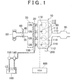
- FIG. 1 shows an inline four-cylinder gasoline engine
- the invention is not limited to such an engine and can be applied to various types of engines such as a V engine with six cylinders (V-6 engine) or V engine with eight cylinders (V-8 engine).
- An engine 10 is an internal combustion engine. As shown in FIG. 1 , the engine 10 is provided with four cylinders 112, and each of the cylinders 112 is connected to a common surge tank 30 through an intake manifold 20. The surge tank 30 is connected to an air cleaner 50 through an intake duct 40.
- a throttle valve 70 driven by an electric motor 60 is arranged within the intake duct 40.
- the throttle valve 70 is controlled so that a throttle opening TA changes in response to an accelerator depression amount.
- throttle opening is controlled by the ISC so that NE becomes a target idling speed. Throttle opening during idling TAISC is corrected in response to engine operating status.
- NE during idling is below a threshold value NE1
- the throttle opening during idling TAISC is corrected so as to increase by a predetermined value.
- the throttle opening during idling TAISC is corrected so as to decrease by a predetermined value.
- a learning value (ISCG) of the throttle opening during idling TAISC namely an air flow rate learning value
- the ISCG is calculated by, for example, increasing the ISCG by a predetermined value in the case the throttle opening during idling TAISC has exceeded a threshold value TAISC1, or decreasing the ISCG by a predetermined value in the case the throttle opening during idling TAISC has fallen below a threshold value TAISC2.
- Each cylinder 112 is coupled to a common exhaust manifold 80, and this exhaust manifold 80 is coupled to a three-way catalytic converter 90.
- a spark plug 110 and an injector 120 which injects fuel towards the intake port and/or intake path, are respectively provided for each cylinder 112.
- the spark plugs 110 and the injectors 120 are controlled based on the output of an electronic control unit (ECU) 900.
- ECU electronice control unit
- Each of the injectors 120 is connected to a delivery pipe 130, and the delivery pipe 130 is connected to an electric motor-driven fuel pump 150 through a fuel pressure regulator 140.
- the fuel pressure regulator 140 is composed such that a portion of fuel discharged from the fuel pump 150 is returned to a fuel tank 160 when the fuel pressure of fuel discharged from the fuel pump 150 exceeds a predetermined set fuel pressure. Thus, the fuel pressure regulator 140 prevents the pressure of fuel supplied to the injectors 120 from exceeding the set fuel pressure.
- the engine 10 starts as a result of being cranked by a starter 200.
- the engine 10 is controlled so as to start when an ignition switch is switched from off to on.
- the engine 10 is stopped when the ignition switch is switched from on to off.
- the engine 10 is controlled so as to stop automatically when idle stop conditions have been satisfied. Namely, idle stop is executed.
- the idle stop conditions include the condition of the vehicle being stopped (vehicle speed is zero), the condition of the accelerator depression amount (ACC) being zero, or the brake pedal being operated (brake pedal is pressed).
- the engine 10 is controlled so as to start automatically in the case starting conditions are satisfied that include the condition of the foot being released from the brake pedal.
- output of the engine 10 is input to a belt-type continuously variable transmission 500 through a torque converter 300 and a forward-reverse switching apparatus 400.
- Output of the continuously variable transmission 500 is transmitted to a reduction gear 600 and a differential gear apparatus 700 and distributed to left and right driving wheels 800.
- a chain-type or toroidal-type continuously variable transmission may be used instead of the belt-type continuously variable transmission 500, or an automatic transmission having a planetary gear unit may be used for the transmission mechanism.
- the torque converter 300 is composed of a pump vane wheel 302 coupled to a crankshaft of the engine 10, and a turbine vane wheel 306 coupled to the forward-reverse switching apparatus 400 through a turbine shaft 304.
- a lockup clutch 308 is provided between the pump vane wheel 302 and the turbine vane wheel 306. The lockup clutch 308 is engaged or released by switching the supply of fluid pressure to an engaging side fluid chamber and releasing side fluid chamber.
- the pump vane wheel 302 and the turbine vane wheel 306 are integrally rotated as a result of the lockup clutch 308 being completely engaged.
- the pump vane wheel 302 is provided with a mechanical oil pump 310 that generates hydraulic pressure for controlling shifting of gears by the continuously variable transmission 500, generating belt clamping pressure or supplying lubricating oil to each component.
- the forward-reverse switching apparatus 400 is composed of a double pinion-type planetary gear apparatus.
- the turbine shaft 304 of the torque converter 300 is coupled to a sun gear 402.
- An input shaft 502 of the continuously variable transmission 500 is coupled to a carrier 404.
- the carrier 404 and the sun gear 402 are coupled through a forward clutch 406.
- a ring gear 408 is fixed to a housing through a reverse brake 410.
- the forward clutch 406 and the reverse clutch 410 are frictionally engaged by a hydraulic cylinder.
- the input rotating speed of the forward clutch 406 is equal to the rotating speed of the turbine shaft 304, namely the turbine rotating speed NT.
- the forward-reverse switching apparatus 400 is engaged for forward operation by engaging the forward clutch 406 and releasing the reverse brake 410. When in this state, driving force in the forward direction is transmitted to the continuously variable transmission 500.
- the forward-reverse switching apparatus 400 is engaged for reverse operation by engaging the reverse brake 410 and releasing the forward clutch 406. When in this state, the input shaft 502 is rotated in the opposite direction of the turbine shaft 304. As a result, driving force in the reverse direction is transmitted to the continuously variable transmission 500.
- both the forward clutch 406 and the reverse brake 410 are released, the forward-reverse switching apparatus 400 enters a neutral state in which transmission of driving force is interrupted.
- the continuously variable transmission 500 is composed of a primary pulley 504 provided on the input haft 502, a secondary pulley 508 provided on an output shaft 506, and a transmission belt 510 wound around these pulleys. Motive power is transmitted by utilizing the frictional force between each pulley and the transmission belt 510.
- Each pulley is composed of a hydraulic cylinder so as to be able to vary groove width.
- the groove width of each pulley is varied by controlling the hydraulic pressure of the hydraulic cylinder of the primary pulley 504.
- the engine rotating speed sensor 902 detects the NE of the engine 10.
- the turbine rotating speed sensor 904 detects the rotating speed NT of the turbine 304 (turbine rotating speed).
- the vehicle speed sensor 906 detects the vehicle speed V.
- the throttle opening sensor 908 detects the opening TA of the throttle valve 70.
- the cooling water temperature sensor 910 detects the cooling water temperature TW of the engine 10.
- the oil temperature sensor 912 detects the oil temperature TC of the continuously variable transmission 500 and the like.
- the accelerator depression amount sensor 914 detects ACC of the accelerator pedal.
- the brake switch 916 detects the presence or absence of operation of the brake pedal.
- the position sensor 918 detects the position (PSH) of a shift lever 920 by determining whether or not a contact provided at a location corresponding to a shift position is on or off.
- the primary pulley rotating speed sensor 922 detects the input shaft rotating speed NIN of the continuous variable transmission 500 (rotating speed of the primary pulley 504).
- the secondary pulley rotating speed sensor 924 detects the output shaft rotating speed NOUT of the continuously variable transmission 500 (rotating speed of the secondary pulley 508). Signals indicating the detection result of each sensor are transmitted to the ECU 900.
- the turbine rotating speed NT coincides with the primary pulley rotating speed NIN when traveling forward with the forward clutch 406 engaged.
- the vehicle speed V is a value that corresponds to the secondary pulley rotating speed NOUT.
- the ECU 900 contains a central processing unit (CPU), memory, input/output interface and the like.
- the CPU processes signals according to a program stored in the memory.
- the CPU executes output control of the engine 10, control of gear shifting of the continuously variable transmission 500, belt clamping pressure control, control of engagement and release of the forward clutch 406, control of engagement and release of the reverse brake 410 and the like according to the signals.
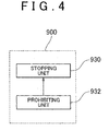
- the following provides an explanation of functions of the ECU 900 with reference to FIG. 4 .
- the functions explained below may be realized with software or realized with hardware.
- the ECU 900 may also be divided among a plurality of ECUs.
- the ECU 900 is provided with a stopping unit 930 and a prohibiting unit 932.
- the stopping unit 930 controls the engine 10 so as to stop automatically in the case predetermined idle stop conditions have been satisfied.
- the prohibiting unit 932 prohibits idle stop, namely prohibits control that causes the engine 10 to stop automatically in the case conditions are satisfied that at least include the condition of the NE of the engine 10 being lower than a predetermined target rotating speed.
- control that causes the engine 10 to stop automatically is prohibited in the case a state in which the NE of the engine 10 is lower than a target rotating speed by a predetermined value ⁇ NE or more continues for a time ⁇ T or more.
- the target rotating speed is determined based on the results of experimentation, simulation and the like within the range of the rotating speed at which the engine 10 is able to operate autonomously, namely the rotating speed at which the engine 10 does not stall.
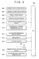
- the following provides an explanation of the control structure of a program executed by the ECU 900 with reference to FIG. 5 .
- the program executed by the ECU 900 may be distributed commercially by recording on a recording medium such as a compact disc (CD) or digital versatile disc (DVD) and the like.
- a step (abbreviated simply as "S") 100 the ECU 900 determines whether or not conditions of the engine 10 not being started, the engine 10 not being stopped, and fuel cutoff not being executed are satisfied. Whether or not the engine 10 is currently operating is then determined on the basis thereof.
- the ECU 900 determines whether or not the NE is lower than a target rotating speed by a predetermined value ⁇ NE or more. If the NE is lower than the target rotating speed by the predetermined value ⁇ NE or more (YES in S102), processing proceeds to S104. If it is not (NO in S102), processing proceeds to S110.
- the ECU 900 determines whether or not the state in which the NE is lower than the target rotating speed by the predetermined value ⁇ NE or more has continued for a predetermined time ⁇ T or more. If the state in which the NE is lower than the target rotating speed by the predetermined value ⁇ NE or more continues for the predetermined time ⁇ T or more (YES in S104), processing proceeds to S 106. If it does not (NO in S 104), processing returns to S 102.
- the ECU 900 prohibits idle stop, namely prohibits control that causes the engine 10 to stop automatically.
- the ECU 900 determines whether or not idle stop conditions have been satisfied. If the idle stop conditions have been satisfied (YES in S110), processing proceeds to S112. If they have been not (NO in S110), processing returns to S100.
- the ECU 900 determines whether or not the engine 10 is to be controlled so as to stop automatically, or in other words, whether or not idle stop is prohibited. If idle stop is prohibited (YES in S112), processing proceeds to S120. If it is not (NO in S 112), processing proceeds to S 114.
- the ECU 900 controls the engine 10 so as to stop automatically.
- the ECU 900 determines whether or not starting conditions have been satisfied. If starting conditions are satisfied (YES in S 116), processing proceeds to S118. If they are not satisfied (NO in S116), processing returns to S 116.
- the ECU 900 controls the engine 10 so that the engine 10 starts.
- the ECU 900 determines whether or not NE during idling has stabilized by learning the throttle opening TAISC during idling. For example, if the state in which the NE during idling is equal to greater than a target idling speed continues for a predetermined time or longer, the NE during idling is judged to have stabilized. Furthermore, the method used to determine whether or not the NE has stabilized is not limited thereto.
- the engine 10 is controlled so as to stop automatically (S114) if the idle stop conditions are satisfied (YES in S110) and idle stop is not prohibited (NO in S 112).
- the engine 10 is controlled so as to start (S 118) if the starting conditions are satisfied (YES in S 116).
- control that causes the engine 10 to stop automatically is prohibited only in the case the engine 10 can be said to be unable to operate autonomously due to the NE having continuously decreased, thereby making it possible to secure an opportunity for the ISC to learn the throttle opening TAISC during idling. Consequently, the frequency at which control that causes the engine 10 to stop automatically is prohibited can be reduced by not prohibiting control that causes the engine 10 to stop automatically in the case the NE has only temporarily decreased. As a result, exacerbation of fuel consumption caused by prohibiting control causing the engine 10 to stop automatically can be reduced.
- control that causes the engine to stop automatically is prohibited.
- an opportunity for the ISC to learn the throttle opening TAISC during idling can be secured by prohibiting control that causes the engine to stop automatically only in the case the engine is unable to operate autonomously due to a decrease in the NE. Consequently, the frequency at which control that causes the engine to stop automatically is prohibited can be reduced by not prohibiting control that causes the engine to stop automatically in the case the engine is able to operate independently. As a result, exacerbation of fuel consumption caused by prohibiting control causing the engine to stop automatically can be reduced.
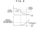
- This embodiment differs from the above-mentioned first embodiment in that, in the case the product of the duration of a state in which the NE during engine operation is lower than a target rotating speed by a predetermined value ⁇ NE or more, and the difference between the NE and the target rotating speed, is equal to or greater than a predetermined value, the engine 10 is controlled so as to stop automatically.
- Other structures of the second embodiment are the same as those of the first embodiment. As such, a detailed explanation thereof is not repeated here.
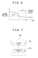
- the following provides an explanation of the functions of the ECU 900 with reference to FIG. 7 .
- the functions explained below may be realized with software or realized with hardware.
- the ECU 900 may also be divided among a plurality of ECUs.
- a prohibiting unit 934 of the ECU 900 in this embodiment prohibits control that causes the engine 10 to stop automatically in the case the product of the duration of a state in which the NE during engine operation is lower than a target rotating speed by a predetermined value ⁇ NE or more, and the difference between the NE and the target rotating speed (absolute value of that difference), is equal to or greater than a predetermined value.
- the ECU 900 determines whether or not the product of the duration of a state in which the NE during engine operation is lower than a target rotating speed by a predetermined value ⁇ NE or more, and the difference between the NE and the target rotating speed, is equal to or greater than a predetermined value.
- processing proceeds to S 106. If it is not (NO in S204), processing returns to S102.
- control that causes the engine 10 to stop automatically is prohibited only in the case the engine 10 can be said to be unable to operate autonomously due to the NE having continuously decreased or the NE having decreased suddenly in a short period of time, thereby making it possible to secure an opportunity for the ISC to learn the throttle opening TAISC during idling. Consequently, the frequency at which control that causes the engine 10 to stop automatically is prohibited can be reduced by not prohibiting control that causes the engine 10 to stop automatically in the case the engine 10 is able to operate autonomously. As a result, exacerbation of fuel consumption caused by prohibiting control causing the engine 10 to stop automatically can be reduced.
Landscapes
- Engineering & Computer Science (AREA)
- Chemical & Material Sciences (AREA)
- Combustion & Propulsion (AREA)
- Mechanical Engineering (AREA)
- General Engineering & Computer Science (AREA)
- Control Of Vehicle Engines Or Engines For Specific Uses (AREA)
- Combined Controls Of Internal Combustion Engines (AREA)
- Output Control And Ontrol Of Special Type Engine (AREA)
Applications Claiming Priority (1)
| Application Number | Priority Date | Filing Date | Title |
|---|---|---|---|
| JP2008185101A JP2010024887A (ja) | 2008-07-16 | 2008-07-16 | エンジンの制御装置 |
Publications (1)
| Publication Number | Publication Date |
|---|---|
| EP2146077A1 true EP2146077A1 (fr) | 2010-01-20 |
Family
ID=41172405
Family Applications (1)
| Application Number | Title | Priority Date | Filing Date |
|---|---|---|---|
| EP09165699A Withdrawn EP2146077A1 (fr) | 2008-07-16 | 2009-07-16 | Appareil de contrôle de moteur |
Country Status (2)
| Country | Link |
|---|---|
| EP (1) | EP2146077A1 (fr) |
| JP (1) | JP2010024887A (fr) |
Cited By (3)
| Publication number | Priority date | Publication date | Assignee | Title |
|---|---|---|---|---|
| CN106014744A (zh) * | 2015-03-26 | 2016-10-12 | 通用汽车环球科技运作有限责任公司 | 用于车辆的自动停止发动机控制 |
| US10788005B2 (en) * | 2012-09-05 | 2020-09-29 | Fpt Industrial S.P.A. | System for controlling an internal combustion engine |
| CN115143005A (zh) * | 2021-03-31 | 2022-10-04 | Tvs电机有限公司 | 怠速停止起动系统 |
Families Citing this family (2)
| Publication number | Priority date | Publication date | Assignee | Title |
|---|---|---|---|---|
| JP5126256B2 (ja) * | 2010-03-12 | 2013-01-23 | 日産自動車株式会社 | アイドルストップ車両 |
| KR101251851B1 (ko) | 2011-11-30 | 2013-04-10 | 현대자동차주식회사 | Isg 시스템 및 이의 제어방법 |
Citations (9)
| Publication number | Priority date | Publication date | Assignee | Title |
|---|---|---|---|---|
| JPH10331675A (ja) * | 1997-06-03 | 1998-12-15 | Nissan Motor Co Ltd | 車両用複合駆動システムの制御装置 |
| EP0908619A1 (fr) * | 1997-10-08 | 1999-04-14 | Toyota Jidosha Kabushiki Kaisha | Dispositif et procédé de commande d'un moteur à combustion interne installé dans un véhicule automobile |
| JP2003247447A (ja) * | 2002-02-22 | 2003-09-05 | Toyota Motor Corp | エンジンの燃料噴射制御装置 |
| EP1382842A2 (fr) * | 2002-07-17 | 2004-01-21 | Toyota Jidosha Kabushiki Kaisha | Dispositif pour contrôler automatiquement l'arrêt et le démarrage d'un moteur à combustion monté sur un véhicule |
| US20050188939A1 (en) * | 2004-02-27 | 2005-09-01 | Aisin Aw Co., Ltd. | Control apparatus for driving vehicle and control method for driving vehicle |
| JP2005325794A (ja) * | 2004-05-17 | 2005-11-24 | Mitsubishi Electric Corp | 内燃機関の制御装置 |
| WO2005116432A1 (fr) * | 2004-05-28 | 2005-12-08 | Toyota Jidosha Kabushiki Kaisha | Dispositif et procede de commande electronique de moteur et vehicule equipe d'un dispositif de commande electronique de moteur se |
| JP2007071178A (ja) | 2005-09-09 | 2007-03-22 | Denso Corp | 車両の学習制御装置 |
| US20070240916A1 (en) * | 2006-04-07 | 2007-10-18 | Helmut Zell | Method and device for operating a drive unit |
-
2008
- 2008-07-16 JP JP2008185101A patent/JP2010024887A/ja active Pending
-
2009
- 2009-07-16 EP EP09165699A patent/EP2146077A1/fr not_active Withdrawn
Patent Citations (9)
| Publication number | Priority date | Publication date | Assignee | Title |
|---|---|---|---|---|
| JPH10331675A (ja) * | 1997-06-03 | 1998-12-15 | Nissan Motor Co Ltd | 車両用複合駆動システムの制御装置 |
| EP0908619A1 (fr) * | 1997-10-08 | 1999-04-14 | Toyota Jidosha Kabushiki Kaisha | Dispositif et procédé de commande d'un moteur à combustion interne installé dans un véhicule automobile |
| JP2003247447A (ja) * | 2002-02-22 | 2003-09-05 | Toyota Motor Corp | エンジンの燃料噴射制御装置 |
| EP1382842A2 (fr) * | 2002-07-17 | 2004-01-21 | Toyota Jidosha Kabushiki Kaisha | Dispositif pour contrôler automatiquement l'arrêt et le démarrage d'un moteur à combustion monté sur un véhicule |
| US20050188939A1 (en) * | 2004-02-27 | 2005-09-01 | Aisin Aw Co., Ltd. | Control apparatus for driving vehicle and control method for driving vehicle |
| JP2005325794A (ja) * | 2004-05-17 | 2005-11-24 | Mitsubishi Electric Corp | 内燃機関の制御装置 |
| WO2005116432A1 (fr) * | 2004-05-28 | 2005-12-08 | Toyota Jidosha Kabushiki Kaisha | Dispositif et procede de commande electronique de moteur et vehicule equipe d'un dispositif de commande electronique de moteur se |
| JP2007071178A (ja) | 2005-09-09 | 2007-03-22 | Denso Corp | 車両の学習制御装置 |
| US20070240916A1 (en) * | 2006-04-07 | 2007-10-18 | Helmut Zell | Method and device for operating a drive unit |
Cited By (4)
| Publication number | Priority date | Publication date | Assignee | Title |
|---|---|---|---|---|
| US10788005B2 (en) * | 2012-09-05 | 2020-09-29 | Fpt Industrial S.P.A. | System for controlling an internal combustion engine |
| CN106014744A (zh) * | 2015-03-26 | 2016-10-12 | 通用汽车环球科技运作有限责任公司 | 用于车辆的自动停止发动机控制 |
| CN106014744B (zh) * | 2015-03-26 | 2018-06-19 | 通用汽车环球科技运作有限责任公司 | 用于车辆的自动停止发动机控制 |
| CN115143005A (zh) * | 2021-03-31 | 2022-10-04 | Tvs电机有限公司 | 怠速停止起动系统 |
Also Published As
| Publication number | Publication date |
|---|---|
| JP2010024887A (ja) | 2010-02-04 |
Similar Documents
| Publication | Publication Date | Title |
|---|---|---|
| US8335621B2 (en) | Vehicle control apparatus | |
| JP5790670B2 (ja) | 車両の制御装置 | |
| US20130110360A1 (en) | Shift control system and shift control method | |
| JP2506630B2 (ja) | Cvt制御方式 | |
| CN102161339A (zh) | 辅助直接起动控制的方法和系统 | |
| JP6206455B2 (ja) | 車両の制御装置 | |
| JP2010024887A (ja) | エンジンの制御装置 | |
| JP2013181408A (ja) | 車両の制御装置 | |
| JP4001146B2 (ja) | 車両用駆動制御装置 | |
| JP6210695B2 (ja) | 制御装置 | |
| JP2012167587A (ja) | 車両の制御装置 | |
| US7415349B2 (en) | Control device and control method for vehicle | |
| JP6292781B2 (ja) | 車両の制御装置 | |
| US10955047B2 (en) | Vehicle control apparatus | |
| US10099698B2 (en) | Control apparatus for vehicle and control method | |
| JP5946383B2 (ja) | 制御装置 | |
| JP6422543B2 (ja) | 制御装置 | |
| JP7647218B2 (ja) | 車両の制御装置 | |
| JP6008692B2 (ja) | 制御装置 | |
| JP6021548B2 (ja) | アイドルストップ車両の制御装置 | |
| JP2008155773A (ja) | 車両の制御装置 | |
| JP6338332B2 (ja) | 内燃機関の制御装置 | |
| JP6257184B2 (ja) | 車両の制御装置 | |
| JP5912682B2 (ja) | 自動変速機の制御装置 | |
| JP6053393B2 (ja) | アイドルストップ車両の制御装置 |
Legal Events
| Date | Code | Title | Description |
|---|---|---|---|
| PUAI | Public reference made under article 153(3) epc to a published international application that has entered the european phase |
Free format text: ORIGINAL CODE: 0009012 |
|
| 17P | Request for examination filed |
Effective date: 20090716 |
|
| AK | Designated contracting states |
Kind code of ref document: A1 Designated state(s): AT BE BG CH CY CZ DE DK EE ES FI FR GB GR HR HU IE IS IT LI LT LU LV MC MK MT NL NO PL PT RO SE SI SK SM TR |
|
| AX | Request for extension of the european patent |
Extension state: AL BA RS |
|
| 17Q | First examination report despatched |
Effective date: 20100823 |
|
| RAP1 | Party data changed (applicant data changed or rights of an application transferred) |
Owner name: TOYOTA JIDOSHA KABUSHIKI KAISHA |
|
| STAA | Information on the status of an ep patent application or granted ep patent |
Free format text: STATUS: EXAMINATION IS IN PROGRESS |
|
| STAA | Information on the status of an ep patent application or granted ep patent |
Free format text: STATUS: THE APPLICATION IS DEEMED TO BE WITHDRAWN |
|
| 18D | Application deemed to be withdrawn |
Effective date: 20181108 |