EP2146082A1 - Soupape de commutation de passage de flux - Google Patents
Soupape de commutation de passage de flux Download PDFInfo
- Publication number
- EP2146082A1 EP2146082A1 EP09163638A EP09163638A EP2146082A1 EP 2146082 A1 EP2146082 A1 EP 2146082A1 EP 09163638 A EP09163638 A EP 09163638A EP 09163638 A EP09163638 A EP 09163638A EP 2146082 A1 EP2146082 A1 EP 2146082A1
- Authority
- EP
- European Patent Office
- Prior art keywords
- housing
- valve
- bearing
- passage
- cooling
- Prior art date
- Legal status (The legal status is an assumption and is not a legal conclusion. Google has not performed a legal analysis and makes no representation as to the accuracy of the status listed.)
- Withdrawn
Links
- 239000000498 cooling water Substances 0.000 claims abstract description 39
- 238000005192 partition Methods 0.000 claims abstract description 20
- 238000001816 cooling Methods 0.000 description 3
- 230000007547 defect Effects 0.000 description 3
- 230000006866 deterioration Effects 0.000 description 3
- 238000004512 die casting Methods 0.000 description 2
- 230000000694 effects Effects 0.000 description 2
- 239000007787 solid Substances 0.000 description 2
- XAGFODPZIPBFFR-UHFFFAOYSA-N aluminium Chemical compound [Al] XAGFODPZIPBFFR-UHFFFAOYSA-N 0.000 description 1
- 229910052782 aluminium Inorganic materials 0.000 description 1
- 238000002485 combustion reaction Methods 0.000 description 1
- 238000004891 communication Methods 0.000 description 1
- 230000001771 impaired effect Effects 0.000 description 1
- 238000000034 method Methods 0.000 description 1
- 238000012986 modification Methods 0.000 description 1
- 230000004048 modification Effects 0.000 description 1
- 230000003134 recirculating effect Effects 0.000 description 1
- 238000007789 sealing Methods 0.000 description 1
Images



Classifications
-
- F—MECHANICAL ENGINEERING; LIGHTING; HEATING; WEAPONS; BLASTING
- F16—ENGINEERING ELEMENTS AND UNITS; GENERAL MEASURES FOR PRODUCING AND MAINTAINING EFFECTIVE FUNCTIONING OF MACHINES OR INSTALLATIONS; THERMAL INSULATION IN GENERAL
- F16K—VALVES; TAPS; COCKS; ACTUATING-FLOATS; DEVICES FOR VENTING OR AERATING
- F16K11/00—Multiple-way valves, e.g. mixing valves; Pipe fittings incorporating such valves
- F16K11/02—Multiple-way valves, e.g. mixing valves; Pipe fittings incorporating such valves with all movable sealing faces moving as one unit
- F16K11/04—Multiple-way valves, e.g. mixing valves; Pipe fittings incorporating such valves with all movable sealing faces moving as one unit comprising only lift valves
- F16K11/052—Multiple-way valves, e.g. mixing valves; Pipe fittings incorporating such valves with all movable sealing faces moving as one unit comprising only lift valves with pivoted closure members, e.g. butterfly valves
-
- F—MECHANICAL ENGINEERING; LIGHTING; HEATING; WEAPONS; BLASTING
- F02—COMBUSTION ENGINES; HOT-GAS OR COMBUSTION-PRODUCT ENGINE PLANTS
- F02M—SUPPLYING COMBUSTION ENGINES IN GENERAL WITH COMBUSTIBLE MIXTURES OR CONSTITUENTS THEREOF
- F02M26/00—Engine-pertinent apparatus for adding exhaust gases to combustion-air, main fuel or fuel-air mixture, e.g. by exhaust gas recirculation [EGR] systems
- F02M26/13—Arrangement or layout of EGR passages, e.g. in relation to specific engine parts or for incorporation of accessories
- F02M26/22—Arrangement or layout of EGR passages, e.g. in relation to specific engine parts or for incorporation of accessories with coolers in the recirculation passage
- F02M26/23—Layout, e.g. schematics
- F02M26/25—Layout, e.g. schematics with coolers having bypasses
- F02M26/26—Layout, e.g. schematics with coolers having bypasses characterised by details of the bypass valve
Definitions
- the present invention relates to a flow passage switching valve to be utilized as for example an EGR cooler bypass valve and used for switching a flow passage of exhaust gas.
- an EGR cooler bypass valve provided in an EGR cooler disclosed in e.g. a Patent Literature listed below.
- This bypass valve is placed in the EGR passage through which high-temperature EGR gas passes and used to switch a flow passage of EGR gas between a passage passing through the EGR cooler and a passage not passing through the EGR cooler.
- an EGR device an exhaust gas recirculation device
- the EGR cooler bypass valve is provided. At the time of engine start or cold temperature, this bypass valve is operated to switch the flow passage of EGR gas to the bypass passage not passing through the EGR cooler.
- the aforementioned bypass valve comprises a metallic housing formed with an inlet and an outlet for EGR gas and a passage for communicating the inlet and the outlet, a swing-arm-shaped valve element for switching the flow passage of EGR gas by allowing or interrupting communication between the inlet and the outlet, a valve shaft integral with the valve element, and a pair of bearings for rotatably supporting both ends of the valve shaft.
- Patent Literature JP2007-100566A
- the present invention has been made in view of the circumstances and has a purpose to provide a flow passage switching valve capable of simply and effectively cooling a bearing.
- one aspect of the present invention provides a flow passage switching valve comprising: a housing having diverged passages through which exhaust gas can flow; a valve element provided in the housing to selectively open and close the diverged passages to switch a flow passage of the exhaust gas; a valve shaft integral with the valve element; and a bearing provided in the housing and configured to rotatably support the valve shaft, part of an outer periphery of the bearing being placed in one of the passages, characterized in that a cooling-water passage is formed near the bearing.
- part of the outer periphery of the bearing is located in the exhaust gas passage of the housing and hence the bearing is exposed directly to the heat of the exhaust gas.
- the cooling water passage is formed near the bearing so that cooling water passing through the cooling water passage can cool the bearing.
- a flow passage switching valve comprising: a housing having diverged passages through which exhaust gas can flow; a valve element provided in the housing to selectively open and close the diverged passages to switch a flow passage of the exhaust gas; a valve shaft integral with the valve element; a bearing provided in the housing and configured to rotatably support the valve shaft, part of an outer periphery of the bearing being placed in one of the passages; and a partition wall provided in the housing next to the bearing, defining the diverged passages and including a valve seat, characterized in that a cooling-water passage is formed near the bearing by the partition wall.
- part of the outer periphery of the bearing is located in the exhaust gas passage of the housing and hence the bearing is exposed directly to the heat of the exhaust gas.
- the cooling water passage is formed in the partition wall near the bearing so that cooling water passing through the cooling water passage can cool the bearing. Furthermore, a space for the cooling-water passage can be ensured by use of the partition wall.
- the cooling-water passage is formed in the housing in parallel with the valve shaft and in almost straight shape.
- the cooling-water passage is formed integral with the housing by pulling out a pin from the die-casted housing in parallel with the bearing when the housing is formed.
- the bearing can be simply and effectively cooled, thereby preventing deterioration in function.
- the cooling-water passage can be formed easily in the housing, thereby achieving cost reduction.
- FIG. 1 is a front view of a bypass valve
- the flow passage switching valve of the present invention is explained as an EGR cooler bypass valve.
- the EGR cooler bypass valve is provided in an EGR device for recirculating part of exhaust gas from an engine to an air intake system.
- FIG. 1 is a front view of an EGR cooler bypass valve (hereinafter, simply referred to as a "bypass valve") 1.
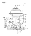
- FIG. 2 is a right side view of the bypass valve 1.
- FIG. 3 is a left side view of the bypass valve 1.
- FIG. 4 is a plan view of the bypass valve 1.
- FIG. 5 is a bottom view of the bypass valve 1.
- FIG. 6 is a cross-sectional view of the bypass valve 1 taken along a line VI-VI in FIG. 2 .
- FIG. 7 is a cross-sectional view of the bypass valve 1 taken along a line VII-VII in FIG. 3 .
- FIG. 8 is a cross-sectional view of the bypass valve 1 taken along a line VIII-VIII in FIG. 4 .
- this bypass valve 1 includes a housing 4 formed with first and second diverged passages 2 and 3 (see FIG. 8 ) through which EGR gas can flow, which is part of the exhaust gas from the engine, a valve element 5 (see FIGs. 4 and 5-8 ) of a plate-like shape to selectively open and close each passage 2 and 3 to switch the flow passage for the EGR gas, a valve shaft 6 (see FIGs. 1 , 5-8 ) integral with the valve element 5, a pair of bearings 7 and 8 (see FIGs. 3-7 ) provided in the housing 4 and configured for rotatably supporting the valve shaft 6, and a diaphragm actuator 9 (see FIGs. 1-5 , 7 , and 8 ) for rotating the valve shaft 6 to swing the valve element 5.
- the housing 4 is made of aluminum by die casting. As shown in FIGs. 1 to 3 , the housing 4 includes a cylindrical gas inflow part 11 protruding upward and a cylindrical gas outflow part 12 protruding forward (for example, leftward in Fig. 2 ).
- the cylindrical gas inflow part 11 includes a gas inlet 11a and a flange 11b at an end thereof.
- the cylindrical gas outflow part 12 includes a gas outlet 12a and a flange 12b at an end thereof.
- an EGR pipe constituting an EGR device is connected to each of the flanges 11b and 12b.
- the housing 4 is provided, at a lower side thereof, with a gas outlet 13 and a gas inlet 14 each opening downward, and a flange 15.
- the gas outlet 13 is communicated with the first passage 2 and the gas inlet 14 is communicated with the second passage 3.
- This flange 15 can be connected to an EGR cooler 31 of a U-flow type as shown in FIG. 8 .
- valve element 5 is fixed to the valve shaft 6 with screws 21 so as to swing about the valve shaft 6 when the valve shaft 6 is rotated.
- the valve element 5 can be selectively disposed in a first position for opening the first passage 2 and closing the second passage 3 as indicated by a solid line in FIG. 8 and a second position for closing the first passage 2 and opening the second passage 3 as indicated by a chain double-dashed line in FIG. 8 . While the valve element 5 is located in the first position, EGR gas flowing in the cylindrical gas inflow part 11 through the gas inlet 11a passes through the first passage 2 to flow in the EGR cooler 31 through the gas outlet 13 as indicated by solid arrows in FIG. 8 .
- the EGR gas circulating through the EGR cooler 31 will then flow in the second passage 3 through the gas inlet 14 and flow outside through the gas outlet 12a as indicated by the solid arrow in FIG. 8 . While the valve element 5 is located in the second position, on the other hand, the EGR gas flowing in the cylindrical gas inflow part 11 through the gas inlet 11a flows from the first passage 2 to the second passage 3 and then flows outside through the gas outlet 12a.
- the bypass valve 1 is configured as above to switch the flow passage of EGR gas between the passage passing through the EGR cooler 31 and the passage not passing through the EGR cooler 31.
- a bush 22 and a resinous seal member 23 are provided around the valve shaft 6.
- an E ring 24 is fit on the outer periphery of the valve shaft 6 to block movement of the valve shaft 6 in a thrust direction.
- One end portion of the valve shaft 6 protrudes out of the housing 4 and an end thereof is coupled with a rod 9a of the actuator 9 via a link member 25.
- the actuator 9 is fixed to the housing 4 through a bracket 26 with bolts 27.
- the actuator 9 is configured to displace a built-in diaphragm (not shown) by negative pressure, thereby extending/contracting the rod 9a, rotating the valve shaft 6 to swing the valve element 5.
- the bypass valve 1 can be configured compact.
- a partition wall 17 is formed to define the diverged second passage 2 and have a valve seat 16 with which the valve element 5 will contact as shown in FIG. 8 .
- this partition wall 17 is formed with a cooling-water passage 18 near the bearings 7 and 8.
- This cooling-water passage 18 is formed in the housing 4 in parallel with the valve shaft 6 and in almost straight shape.
- a distance between the bearings 7 and 8 and the cooling-water passage 18 is determined to be about "1.5 mm to 3.0 mm" to keep required sufficient thickness of the housing 4.
- the cooling-water passage 18 is formed at the same time as the die casting process for the housing 4. As shown in FIG.
- pipe joints 28 and 29 are fitted in openings 18a at both ends of the cooling-water passage 18.
- One pipe joint 28 has a straight shape and the other pipe joint 29 has a bent shape to avoid interference with the rod 9a of the actuator 9.
- Each of the pipe joints 28 and 29 is connected to a cooling-water pipe for circulating cooling-water of the engine.
- the valve 1 is provided in the EGR cooler 31 of the EGR device and hence can switch the flow passage of EGR gas between the passage passing through the EGR cooler 31 and the passage not passing through the EGR cooler 31.
- this bypass valve 1 part of the outer periphery of each bearing 7 and 8 is located and exposed in the first passage 2, the bearings 7 and 8 will be exposed directly to the heat of the high-temperature EGR gas. Accordingly, the bearings 7 and 8 may be thermally deformed, resulting in deterioration in bearing function.
- the cooling-water passage 18 is provided in the partition wall 17 near the bearings 7 and 8 to allow the cooling-water of the engine to flow in this cooling-water passage 18.
- the cooling-water flowing in the cooling-water passage 18 cools the partition wall 17, thereby cooling the bearings 7 and 8 through the partition wall 17.
- the space for the cooling-water passage 18 can be ensured by use of the partition wall 17 formed in the housing 4.
- the bearings 7 and 8 provided in the housing 4 therefore can be cooled simply and effectively. This makes it possible to prevent thermal deformation of the bearings 7 and 8 and other defects, and retain the bearing function of the bearings 7 and 8. Since the bearings 7 and 8 are effectively cooled, the seal member 23 provided in each of the bearings 7 and 8 can have heat resistance to enhance a sealing performance. It is accordingly possible to prevent gas leakage from the bearings 7 and 8.
- the partition wall 17 is provided in substantially the center of the housing 4 and the cooling-water passage 18 is formed in such partition wall 17. Accordingly, the partition wall 17 can be cooled, so that the entire housing 4 can also be effectively cooled.
- the cooling-water passage 18 is formed in the housing 4 in parallel with the valve shaft 6 and in almost straight shape. Accordingly, when the housing 4 is molded, a pinhole is formed in parallel with the bearings 7 and 8 by pulling out a pin from the die-casted housing 4, thereby forming the cooling-water passage 18. Consequently, the cooling-water passage 18 can be easily provided in the housing 4 with an advantage of cost reduction.
- the cooling-water passage 18 is formed in the partition wall 17.
- the cooling-water passage may be formed in a different portion other than the partition wall 17 if only the cooling-water passage is located near the bearings 7 and 8.
- the present invention can be utilized to switch the flow passage of EGR gas in the EGR cooler bypass valve mounted in the EGR device.
Landscapes
- Engineering & Computer Science (AREA)
- General Engineering & Computer Science (AREA)
- Mechanical Engineering (AREA)
- Chemical & Material Sciences (AREA)
- Combustion & Propulsion (AREA)
- Exhaust-Gas Circulating Devices (AREA)
- Multiple-Way Valves (AREA)
- Details Of Valves (AREA)
Applications Claiming Priority (1)
| Application Number | Priority Date | Filing Date | Title |
|---|---|---|---|
| JP2008184549A JP5074317B2 (ja) | 2008-07-16 | 2008-07-16 | 流路切替弁 |
Publications (1)
| Publication Number | Publication Date |
|---|---|
| EP2146082A1 true EP2146082A1 (fr) | 2010-01-20 |
Family
ID=41361348
Family Applications (1)
| Application Number | Title | Priority Date | Filing Date |
|---|---|---|---|
| EP09163638A Withdrawn EP2146082A1 (fr) | 2008-07-16 | 2009-06-24 | Soupape de commutation de passage de flux |
Country Status (2)
| Country | Link |
|---|---|
| EP (1) | EP2146082A1 (fr) |
| JP (1) | JP5074317B2 (fr) |
Cited By (1)
| Publication number | Priority date | Publication date | Assignee | Title |
|---|---|---|---|---|
| WO2011090855A3 (fr) * | 2010-01-25 | 2011-10-27 | G.W. Lisk Company, Inc. | Tiroir sélecteur pour un moteur à combustion interne |
Families Citing this family (6)
| Publication number | Priority date | Publication date | Assignee | Title |
|---|---|---|---|---|
| DE102011079343B4 (de) | 2010-07-20 | 2020-08-06 | Aisan Kogyo Kabushiki Kaisha | EGR-Kühlerbypassventil, EGR-Kühlersystem und EGR-System |
| US9664087B2 (en) | 2010-07-22 | 2017-05-30 | Wescast Industries, Inc. | Exhaust heat recovery system with bypass |
| JP2012149725A (ja) * | 2011-01-20 | 2012-08-09 | Nok Corp | 密封装置及びその製造方法 |
| JP5857716B2 (ja) * | 2011-12-19 | 2016-02-10 | 株式会社デンソー | Egr装置 |
| US9611818B2 (en) | 2014-12-03 | 2017-04-04 | Hyundai Motor Company | Integrated EGR valve housing |
| JP6869834B2 (ja) * | 2017-07-06 | 2021-05-12 | 愛三工業株式会社 | 排気制御弁 |
Citations (5)
| Publication number | Priority date | Publication date | Assignee | Title |
|---|---|---|---|---|
| JP2007100566A (ja) | 2005-10-03 | 2007-04-19 | Aisan Ind Co Ltd | 流路切替弁 |
| WO2007125118A1 (fr) | 2006-04-28 | 2007-11-08 | Dayco Ensa, S.L. | Echangeur de chaleur en aluminium destine a un systeme 'egr' |
| FR2907890A1 (fr) * | 2006-10-27 | 2008-05-02 | Valeo Sys Controle Moteur Sas | Ensemble de vanne egr-by pass et dispositif d'echange thermique equipe d'un tel ensemble de vanne. |
| DE102006052972A1 (de) * | 2006-11-10 | 2008-05-15 | Audi Ag | Abgaskühler |
| FR2917801A1 (fr) * | 2007-06-21 | 2008-12-26 | Faurecia Sys Echappement | Vanne trois voies pour une ligne d'echappement de vehicule automobile et methode de fabrication d'une telle vanne |
Family Cites Families (3)
| Publication number | Priority date | Publication date | Assignee | Title |
|---|---|---|---|---|
| JPH07259660A (ja) * | 1994-03-18 | 1995-10-09 | Honda Motor Co Ltd | 内燃機関の排気還流弁 |
| JP4054478B2 (ja) * | 1999-03-31 | 2008-02-27 | 日産ディーゼル工業株式会社 | Egrバルブ冷却構造 |
| JP2007132310A (ja) * | 2005-11-11 | 2007-05-31 | Denso Corp | 排気ガス再循環装置の排気ガス冷却装置 |
-
2008
- 2008-07-16 JP JP2008184549A patent/JP5074317B2/ja not_active Expired - Fee Related
-
2009
- 2009-06-24 EP EP09163638A patent/EP2146082A1/fr not_active Withdrawn
Patent Citations (5)
| Publication number | Priority date | Publication date | Assignee | Title |
|---|---|---|---|---|
| JP2007100566A (ja) | 2005-10-03 | 2007-04-19 | Aisan Ind Co Ltd | 流路切替弁 |
| WO2007125118A1 (fr) | 2006-04-28 | 2007-11-08 | Dayco Ensa, S.L. | Echangeur de chaleur en aluminium destine a un systeme 'egr' |
| FR2907890A1 (fr) * | 2006-10-27 | 2008-05-02 | Valeo Sys Controle Moteur Sas | Ensemble de vanne egr-by pass et dispositif d'echange thermique equipe d'un tel ensemble de vanne. |
| DE102006052972A1 (de) * | 2006-11-10 | 2008-05-15 | Audi Ag | Abgaskühler |
| FR2917801A1 (fr) * | 2007-06-21 | 2008-12-26 | Faurecia Sys Echappement | Vanne trois voies pour une ligne d'echappement de vehicule automobile et methode de fabrication d'une telle vanne |
Cited By (2)
| Publication number | Priority date | Publication date | Assignee | Title |
|---|---|---|---|---|
| WO2011090855A3 (fr) * | 2010-01-25 | 2011-10-27 | G.W. Lisk Company, Inc. | Tiroir sélecteur pour un moteur à combustion interne |
| US8707996B2 (en) | 2010-01-25 | 2014-04-29 | G. W. Lisk Company, Inc. | Selector valve for an internal combustion engine |
Also Published As
| Publication number | Publication date |
|---|---|
| JP2010024872A (ja) | 2010-02-04 |
| JP5074317B2 (ja) | 2012-11-14 |
Similar Documents
| Publication | Publication Date | Title |
|---|---|---|
| CN108005774B (zh) | 控制阀 | |
| JP4468277B2 (ja) | 流路切替弁 | |
| JP6186276B2 (ja) | バイパスを備える排熱回収装置 | |
| JP4065239B2 (ja) | 排気ガス再循環装置 | |
| JP5015167B2 (ja) | 2つの出口間に作動手段を備えるバルブ装置 | |
| CN100439694C (zh) | 内燃机排气回流装置 | |
| JP7146540B2 (ja) | 制御バルブ | |
| JP2008545082A (ja) | 冷却装置と排気ガス再循環装置とを備えた内燃機関 | |
| JP5074317B2 (ja) | 流路切替弁 | |
| EP1426604A2 (fr) | Soupape de commutation à passage d'écoulement | |
| US20090056682A1 (en) | EGR cooler bypass switching system | |
| CN111750136A (zh) | 控制阀 | |
| EP1853812B1 (fr) | Vanne de derivation | |
| EP2215345B1 (fr) | Module integre d'egr/refroidissement pour un moteur a combustion interne | |
| US9964075B2 (en) | Exhaust-gas heat exchanger with bypass pipe | |
| KR101399417B1 (ko) | Egr 쿨러의 바이패스밸브 조립체 | |
| US10408170B2 (en) | EGR cooler bypass valve | |
| EP3090161B1 (fr) | Turbocompresseur comportant une étanchéité de soupape de dérivation améliorée | |
| JP2010203362A (ja) | 排気ガス切替弁 | |
| CN113167165A (zh) | 排气热量回收系统 | |
| JP7142150B2 (ja) | 制御バルブ | |
| JP2009156488A (ja) | 熱交換器の取付構造 | |
| JP2018071414A (ja) | 排気熱回収装置 | |
| JP4902590B2 (ja) | 排気ガス通路切替弁 | |
| KR20150101931A (ko) | 통합형 서모스탯 밸브 및 과급 공기 쿨러 덮개 조립체 |
Legal Events
| Date | Code | Title | Description |
|---|---|---|---|
| PUAI | Public reference made under article 153(3) epc to a published international application that has entered the european phase |
Free format text: ORIGINAL CODE: 0009012 |
|
| 17P | Request for examination filed |
Effective date: 20090624 |
|
| AK | Designated contracting states |
Kind code of ref document: A1 Designated state(s): AT BE BG CH CY CZ DE DK EE ES FI FR GB GR HR HU IE IS IT LI LT LU LV MC MK MT NL NO PL PT RO SE SI SK TR |
|
| 17Q | First examination report despatched |
Effective date: 20110617 |
|
| STAA | Information on the status of an ep patent application or granted ep patent |
Free format text: STATUS: THE APPLICATION IS DEEMED TO BE WITHDRAWN |
|
| 18D | Application deemed to be withdrawn |
Effective date: 20140103 |