EP2146107A2 - Agencement de protection pour un joint universel double - Google Patents
Agencement de protection pour un joint universel double Download PDFInfo
- Publication number
- EP2146107A2 EP2146107A2 EP09007747A EP09007747A EP2146107A2 EP 2146107 A2 EP2146107 A2 EP 2146107A2 EP 09007747 A EP09007747 A EP 09007747A EP 09007747 A EP09007747 A EP 09007747A EP 2146107 A2 EP2146107 A2 EP 2146107A2
- Authority
- EP
- European Patent Office
- Prior art keywords
- bellows
- arrangement according
- adapter ring
- fastening
- protective
- Prior art date
- Legal status (The legal status is an assumption and is not a legal conclusion. Google has not performed a legal analysis and makes no representation as to the accuracy of the status listed.)
- Granted
Links
Images


Classifications
-
- F—MECHANICAL ENGINEERING; LIGHTING; HEATING; WEAPONS; BLASTING
- F16—ENGINEERING ELEMENTS AND UNITS; GENERAL MEASURES FOR PRODUCING AND MAINTAINING EFFECTIVE FUNCTIONING OF MACHINES OR INSTALLATIONS; THERMAL INSULATION IN GENERAL
- F16D—COUPLINGS FOR TRANSMITTING ROTATION; CLUTCHES; BRAKES
- F16D3/00—Yielding couplings, i.e. with means permitting movement between the connected parts during the drive
- F16D3/84—Shrouds, e.g. casings, covers; Sealing means specially adapted therefor
- F16D3/843—Shrouds, e.g. casings, covers; Sealing means specially adapted therefor enclosed covers
- F16D3/845—Shrouds, e.g. casings, covers; Sealing means specially adapted therefor enclosed covers allowing relative movement of joint parts due to the flexing of the cover
-
- F—MECHANICAL ENGINEERING; LIGHTING; HEATING; WEAPONS; BLASTING
- F16—ENGINEERING ELEMENTS AND UNITS; GENERAL MEASURES FOR PRODUCING AND MAINTAINING EFFECTIVE FUNCTIONING OF MACHINES OR INSTALLATIONS; THERMAL INSULATION IN GENERAL
- F16D—COUPLINGS FOR TRANSMITTING ROTATION; CLUTCHES; BRAKES
- F16D3/00—Yielding couplings, i.e. with means permitting movement between the connected parts during the drive
- F16D3/16—Universal joints in which flexibility is produced by means of pivots or sliding or rolling connecting parts
- F16D3/26—Hooke's joints or other joints with an equivalent intermediate member to which each coupling part is pivotally or slidably connected
- F16D3/30—Hooke's joints or other joints with an equivalent intermediate member to which each coupling part is pivotally or slidably connected in which the coupling is specially adapted to constant velocity-ratio
- F16D3/32—Hooke's joints or other joints with an equivalent intermediate member to which each coupling part is pivotally or slidably connected in which the coupling is specially adapted to constant velocity-ratio by the provision of two intermediate members each having two relatively perpendicular trunnions or bearings
-
- Y—GENERAL TAGGING OF NEW TECHNOLOGICAL DEVELOPMENTS; GENERAL TAGGING OF CROSS-SECTIONAL TECHNOLOGIES SPANNING OVER SEVERAL SECTIONS OF THE IPC; TECHNICAL SUBJECTS COVERED BY FORMER USPC CROSS-REFERENCE ART COLLECTIONS [XRACs] AND DIGESTS
- Y10—TECHNICAL SUBJECTS COVERED BY FORMER USPC
- Y10S—TECHNICAL SUBJECTS COVERED BY FORMER USPC CROSS-REFERENCE ART COLLECTIONS [XRACs] AND DIGESTS
- Y10S464/00—Rotary shafts, gudgeons, housings, and flexible couplings for rotary shafts
- Y10S464/904—Homokinetic coupling
- Y10S464/905—Torque transmitted via radially extending pin
Definitions
- the invention relates to a protective arrangement for a rotating about a rotation axis arranged double universal joint, comprising a tubular protective funnel having connecting means for non-rotatably connecting the protective funnel with a propeller shaft protection connected to the double universal joint shaft, and a sliding ring which, for the rotational support of the protective arrangement on the Double universal joint can be rotatably mounted rotatably connected to the protective funnel.
- a protective arrangement of this kind is known from DE 101 53 822 C1 known, wherein the protective funnel is arranged around a first universal joint of the double universal joint.
- About connecting means in the form of retaining projections of the protective funnel is rotatably connected to a protective element which is connected on the one hand with the protective funnel and on the other hand with the propeller shaft protection and is in the form of a lattice structure.
- the protective element is designed to be flexible in order to compensate for angular deviations.
- a first end of the protective funnel, which is arranged facing away from the protective element projects beyond the sliding ring and partially conceals a second universal joint of the double universal joint. Nevertheless, there is the danger at the first end of the protective funnel that operating personnel can grasp rotating components of the double-jointed joint.
- Object of the present invention is therefore to provide a protective device of the type mentioned, in which a complete protection of the double universal joint is given.
- a protective arrangement mentioned above wherein an adapter ring is provided, which is rotatably connected to the protective funnel and wherein a bellows is provided, which is rotatably connected to the adapter ring and the connecting means for non-rotatably connecting the bellows with a stationary component having.
- both the sliding ring and the protective funnel are adapted to the size of the double-jointed joint.
- an adapter ring may be provided which is adapted so that it can be placed on each one size of a protective funnel, all adapter rings for differently sized protective funnel are in turn designed such that a common size of a bellows can be connected to the adapter ring.
- the protective funnel has a first end, with which the protective funnel is connected both to the sliding ring and to the adapter ring.
- the adapter ring can be arranged around the sliding ring.
- the protective funnel can not or only slightly survive on the slide ring, so that the length of the bellows is as large as possible in order to compensate for angle adjustments in a favorable manner.
- both the protective funnel and the adapter ring can be connected to the sliding ring.
- the bellows has a mounting portion with which it is connected to the adapter ring.
- the adapter ring has a fastening receptacle, in which the attachment portion of the bellows is received and held.
- the fastening receptacle has at least one first fastening surface facing the protective cone, against which the fastening portion of the bellows is held.
- a single first attachment surface is provided, which is arranged circumferentially around the axis of rotation.
- the fastening receptacle has at least one second fastening surface facing the bellows, against which the fastening portion of the bellows is held.
- a plurality of second attachment surfaces may be provided, which are each formed by a projection on the adapter ring.
- the second attachment surfaces are arranged on a circumferential imaginary sheath plane.
- a single circumferential bellows facing the second mounting surface may be provided which forms an attachment groove together with exactly one circumferential first mounting surface.
- the attachment groove is formed in particular as réelle laboratoriessnut.
- the attachment surfaces may be designed conically, in each case based on the axis of rotation, or, in the case of a plurality of first or second attachment surfaces, may be arranged on a cone-shaped imaginary lateral surface.
- the bellows has a plurality of circumferential folds, which are each formed by two flanks, and that the attachment portion of the bellows comprises a fold, the flanks of which lie against each other and against the at least one first attachment surface in plant are held.
- the attachment portion can thus be easily introduced between the at least one first attachment surface and the at least one second attachment surface.
- the adapter ring is already connected to the bellows, without further fastening means would be required.
- the attachment portion of the bellows is between the at least one first attachment surface and the clamped at least a second attachment surface or snapped into the space between the attachment surfaces.
- the length of the bellows can be easily adapted by corresponding to the required Faltenbalgin wrinkles are cut off. If all the folds have the same outside and inside diameters, each fold can serve as a mounting portion, which in turn reduces the variety of parts, because one and the same bellows are used for different lengths due to the use of different adapter rings for different guard funnels and because of the possibility of cutting individual folds can be.
- the adapter ring After preassembly of the adapter ring with the bellows, the adapter ring can be fastened to the protective funnel with fastening screws.
- At least a part of the fastening screws can also be screwed into the sliding ring.
- attachment portion of the bellows is held between the at least one first attachment surface of the adapter ring and the protective funnel.
- fixing screws can be screwed through the adapter ring and through the attachment portion of the bellows in the protective funnel.
- FIG. 1 shows a double universal joint 1 with a double fork 2.
- the double fork 2 is part of a first universal joint 3 and a second universal joint 4.
- the first universal joint 3 includes a first inner fork 5, which is part of the double fork 2.
- the first inner fork 5 is connected via a first pin cross 6 with a first outer fork 7.
- the first outer fork 7 has a receptacle, not shown, in the form of an opening into which a tube 9 of a yoke is inserted and which is secured by a clamping pin 12 to the first outer fork 7.
- the tube 9 is shown here only partially and is connected at an end, not shown, with another universal joint or a double universal joint and thus forms a cardan shaft.
- the double fork 2 has a second inner fork 11, which is connected via a second spider 12 with a second outer fork 13.
- the second outer fork 13 is designed as a connecting fork and serves to connect the double universal joint 1 with, for example, a power take-off shaft of a transmission.
- the second outer fork 13 on a connecting bore, not shown, which is formed with a longitudinal toothing, with which the second outer fork 13 can be pushed onto a correspondingly toothed shaft portion.
- a stationary protection arrangement is provided.
- This includes a protective funnel 15 which is non-rotatably connected to a sliding ring 16.
- the slip ring 16 is disposed within the protective funnel 15 and is rotatably slidably received in a groove 17 of the double fork 2.
- the protective funnel 15 is arranged around the first universal joint 3 and is rotatably connected via a protective element 18 with a protective tube 19.
- the protective tube 19 is connected to a sliding ring 20 which is rotatably received in a groove 21 of the first outer fork 7.
- the protective tube 19 serves to protect the tube 9 and is arranged around this.
- the protective element 18 is provided, which is designed to be elastic, in order to compensate for angular deviations between the protective funnel 15 and the protective tube 19 can.
- the protective element 18 is designed as a membrane in the present case.
- the protective funnel 15 has connecting means in the form of a retaining slot 41, in which a holding portion 42 of the protective element 18 is received and secured.
- a bellows 23 is provided, which is connected to an adapter ring 22.
- the adapter ring 22 is in turn firmly connected to the protective funnel 15.
- this has a fastening portion 24 which is fastened in a fastening receptacle 25 of the adapter ring 22.
- the bellows 23 is arranged around the second universal joint 4 and has at one end remote from the adapter ring 22 connecting means in the form of a connecting portion 26, with which the bellows 23 by means of a clamping band 14 is rotatably attached to a transmission housing 8.
- the bellows has a plurality of folds 27, each having a first flank 28 and a second flank 29.
- the flanks 28, 29 are designed conical, with the flanks 28, 29 are arranged at an angle to each other.
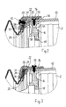
- FIGS. 2 and 3 show enlarged sectional views of the protective arrangement in the region of the adapter ring according to a first embodiment, wherein the sections according to the FIGS. 2 and 3 are arranged in different planes radially to the axis of rotation D.
- the adapter ring 22 has a fastening receptacle 25 in the form of an inner circumferential groove.
- the inner circumferential groove comprises a first attachment surface 30, which faces the protective funnel 15, and a second attachment surface 31, which faces the bellows 23.
- the two attachment surfaces 30, 31 face each other and together form the inner circumferential groove.
- the fastening receptacle 25 can also be designed as an outer circumferential groove.
- a fold 27 of the bellows 23 is arranged in the fastening receptacle 25 in the form of the inner circumferential groove. This is the one fold 27, which is located closest to the protective funnel 15.
- the two flanks 28, 29 of the fold 27 are folded towards each other and thus in contact with each other and aligned parallel to each other.
- the two flanks 28, 29 are arranged conically, with the cone opens to the protective funnel 15.
- the fastening receptacle 25 is configured correspondingly cone-shaped.
- the first flank 28 is held in contact with the first attachment surface 30 and the second flank 29 in abutment with the second attachment surface 31.
- Alone by the inclusion of the fold 27 in the mounting receptacle 25 of the adapter ring 22 is already held on the bellows 23.
- fastening screws 32 are provided, which are screwed from the outside through the adapter ring 22 into the mounting receptacle 25, wherein the fastening screws 32, the fastening receptacle 25 penetrate once and immerse again in the second mounting surface 21.
- the mounting screws 32 screwed through the fold 27 of the bellows 23, so that the adapter ring 22 is secured to the bellows 23.
- the pre-assembled adapter ring 22 can first be attached to the protective funnel 15.
- the protective funnel 15 is connected via fastening screws 33 with the sliding ring 16, wherein the fastening screws 33 are screwed from the outside through the protective funnel 15 radially inwardly into the sliding ring 16.
- the fastening screws 33 each project with their screw head over the outer peripheral surface of the protective funnel 15.
- the adapter ring 22 has a connecting portion 34, which is designed approximately cylindrical, and with which the adapter ring 22 is seated on the protective funnel 15.
- this has a contact surface 36 which is arranged at an angle to the axis of rotation D.
- the contact surface 36 comes into abutment with the fastening screws 33, so that the connecting portion 34 is widened at the points of the connecting screws 33 on further pushing.
- a recess 35 is provided for each fastening screw 33, which is adapted to the protruding portion of the connecting screw 33.
- each recess 35 can completely accommodate the screw head of one of the fastening screws 33 and is adapted in its dimensions to the screw head.
- the connecting portion 34 Upon complete pushing of the connecting portion 34 thus immerses the mounting screw 33 in the recess 35, so that the connecting portion 34 can spring back to its original position.
- the connecting portion 34 is fitted or clipped onto the fixing screws 33 and held on this provisionally.
- further fastening screws 39 are provided, which are screwed from the outside into the connecting portion 34 radially inwardly until they are screwed into the connecting funnel 15.
- the connecting screws may be arranged in the axial direction relative to the axis of rotation in such a way that they also dip simultaneously into the sliding ring 16.
- the fastening screws are arranged laterally offset from the sliding ring 16 and are screwed only in the protective funnel 15.
- securing cam 38 To prevent rotation or to relieve the mounting screws is one or more radially inwardly projecting securing cam 38, which are provided on the adapter ring 22.
- the securing cams 38 engage radially in securing recesses 37 of the protective funnel 15, so that the adapter ring 22 is supported against the securing recess 37 in the circumferential direction via the securing cams 38.
- torque is supported via the securing cams 38 and not via the fastening screws which connect the adapter ring 22 to the protective funnel 15.
- FIGS. 4 and 5 show a second embodiment of a protective arrangement according to the invention, wherein the attachment of the adapter ring on the protective funnel 15 is identical to the attachment according to the first embodiment.
- FIG. 4 shows, however, that the fastening receptacle 25 is formed by a first fastening surface 30, which is designed circumferentially, and by a second fastening surfaces 31 facing the first fastening surface 30, wherein the second fastening surfaces 31 are each formed by one of the securing cams 38.
- the adapter ring 22 can be fixed on the bellows 23 during pre-assembly.
- the received in the mounting receptacle 25 folds 27 is pressed by the first mounting surface against the first end 40 of the protective funnel 15, so that the fold 27 between the first end 40 of the protective funnel 15 and the first mounting surface 30 is clamped and secured is.
- mounting screws 32 ( Fig. 5 ), which is screwed from the outside into the adapter ring 22, comparable to the first embodiment. The fastening screws 32 are then screwed through the fold 27 in the first end 40 of the protective funnel 15.
Landscapes
- Engineering & Computer Science (AREA)
- General Engineering & Computer Science (AREA)
- Mechanical Engineering (AREA)
- Diaphragms And Bellows (AREA)
- Sealing Devices (AREA)
- Joints Allowing Movement (AREA)
- Tires In General (AREA)
Applications Claiming Priority (1)
| Application Number | Priority Date | Filing Date | Title |
|---|---|---|---|
| DE102008033920A DE102008033920B3 (de) | 2008-07-18 | 2008-07-18 | Schutzanordnung für ein Doppelkreuzgelenk |
Publications (3)
| Publication Number | Publication Date |
|---|---|
| EP2146107A2 true EP2146107A2 (fr) | 2010-01-20 |
| EP2146107A3 EP2146107A3 (fr) | 2010-12-15 |
| EP2146107B1 EP2146107B1 (fr) | 2012-02-29 |
Family
ID=41137577
Family Applications (1)
| Application Number | Title | Priority Date | Filing Date |
|---|---|---|---|
| EP09007747A Active EP2146107B1 (fr) | 2008-07-18 | 2009-06-12 | Agencement de protection pour un joint universel double |
Country Status (4)
| Country | Link |
|---|---|
| US (1) | US8202171B2 (fr) |
| EP (1) | EP2146107B1 (fr) |
| AT (1) | ATE547641T1 (fr) |
| DE (1) | DE102008033920B3 (fr) |
Cited By (1)
| Publication number | Priority date | Publication date | Assignee | Title |
|---|---|---|---|---|
| WO2019120710A1 (fr) * | 2017-12-22 | 2019-06-27 | Sparex Limited | Support protecteur pour joints et arbres de prise de force |
Families Citing this family (5)
| Publication number | Priority date | Publication date | Assignee | Title |
|---|---|---|---|---|
| DE102015106697B4 (de) * | 2015-04-29 | 2018-02-08 | Gkn Walterscheid Gmbh | Schutzanordnung für eine Gelenkwelle |
| CN108180229A (zh) * | 2017-12-29 | 2018-06-19 | 北京汽车研究总院有限公司 | 一种传动轴、传动系统及车辆 |
| US20240196794A1 (en) * | 2022-12-14 | 2024-06-20 | Cnh Industrial America Llc | Work vehicle with flexible power take-off shield |
| US11796009B1 (en) * | 2023-01-27 | 2023-10-24 | Ryan D. Hunter | Cover for a universal joint of a driveshaft |
| FR3162808A1 (fr) * | 2024-06-03 | 2025-12-05 | Stellantis Auto Sas | Joint de transmission |
Citations (1)
| Publication number | Priority date | Publication date | Assignee | Title |
|---|---|---|---|---|
| DE10153822C1 (de) | 2001-11-05 | 2003-04-24 | Walterscheid Gmbh Gkn | Schutzanordnung für ein Gelenk, insbesondere Doppelkreuzgelenk |
Family Cites Families (18)
| Publication number | Priority date | Publication date | Assignee | Title |
|---|---|---|---|---|
| US830203A (en) * | 1906-04-02 | 1906-09-04 | Fred H Bogart | Universal joint. |
| US2027329A (en) * | 1934-11-03 | 1936-01-07 | Packard Motor Car Co | Motor vehicle |
| US2255172A (en) * | 1940-02-01 | 1941-09-09 | Corydon M Johnson | Combined universal joint and bearing |
| US2857975A (en) * | 1953-12-31 | 1958-10-28 | Gen Motors Corp | Vehicle half axle drive assembly |
| GB899511A (en) * | 1959-11-13 | 1962-06-27 | Moss Gear Company Ltd | Improvements relating to power transmitting shafts |
| CH381478A (de) * | 1959-11-21 | 1964-08-31 | Atkinsons Agricultural Appl | Sicherheitsschutzvorrichtung für Gelenkwellenkupplungen |
| DE1966532U (de) * | 1967-05-02 | 1967-08-17 | Landmaschinenfabrik Essen G M | Gelenkwellenschutz. |
| DE1966532C3 (de) | 1968-10-17 | 1978-06-15 | Swiss Aluminium Ltd., Chippis (Schweiz) | Horizontale Kokillenanordnung für eine kontinuierlich arbeitende Stranggießmaschine |
| DE2810942C3 (de) * | 1978-03-14 | 1981-04-23 | Uni-Cardan Ag, 5200 Siegburg | Dichtungsanordnung |
| US4605332A (en) * | 1985-04-12 | 1986-08-12 | Weasler Engineering, Inc. | Universal joint guard |
| JPH0765627B2 (ja) * | 1986-06-05 | 1995-07-19 | ヤマハ発動機株式会社 | 車輌用伝動軸装置のカバー装置 |
| JP3388923B2 (ja) * | 1994-12-02 | 2003-03-24 | エヌオーケー株式会社 | アダプタ付ブーツ |
| IT1286696B1 (it) * | 1996-08-14 | 1998-07-15 | Edi Bondioli | Albero di trasmissione cardanico in specie a cannocchiale,con guaina di protezione e cuffie di protezione delle forcelle terminali |
| DE19829314C1 (de) * | 1998-07-01 | 2000-06-29 | Walterscheid Gmbh Gkn | Schutzvorrichtung für eine Antriebsanordnung mit einem Doppelkreuzgelenk |
| NL1016492C2 (nl) * | 1999-11-05 | 2001-05-08 | Walterscheid Gmbh Gkn | Bescherminrichting voor een aandrijfordening met een dubbele kruiskoppeling. |
| DE10037041C2 (de) * | 1999-11-05 | 2003-04-17 | Walterscheid Gmbh Gkn | Schutzvorrichtung für eine Antriebsanordnung mit einem Doppelkreuzgelenk |
| DE10352162B3 (de) * | 2003-11-05 | 2005-06-30 | Gkn Walterscheid Gmbh | Schutzanordnung |
| US7543678B2 (en) * | 2006-05-19 | 2009-06-09 | Gm Global Technology Operations, Inc. | Floating torque tube propeller shaft assembly |
-
2008
- 2008-07-18 DE DE102008033920A patent/DE102008033920B3/de not_active Expired - Fee Related
-
2009
- 2009-06-12 EP EP09007747A patent/EP2146107B1/fr active Active
- 2009-06-12 AT AT09007747T patent/ATE547641T1/de active
- 2009-07-16 US US12/503,890 patent/US8202171B2/en not_active Expired - Fee Related
Patent Citations (1)
| Publication number | Priority date | Publication date | Assignee | Title |
|---|---|---|---|---|
| DE10153822C1 (de) | 2001-11-05 | 2003-04-24 | Walterscheid Gmbh Gkn | Schutzanordnung für ein Gelenk, insbesondere Doppelkreuzgelenk |
Cited By (3)
| Publication number | Priority date | Publication date | Assignee | Title |
|---|---|---|---|---|
| WO2019120710A1 (fr) * | 2017-12-22 | 2019-06-27 | Sparex Limited | Support protecteur pour joints et arbres de prise de force |
| US11668351B2 (en) | 2017-12-22 | 2023-06-06 | Sparex Limited | Safety guard support for power take off joints and shafts |
| AU2018387538B2 (en) * | 2017-12-22 | 2023-10-05 | Sparex Limited | Safety guard support for power take off joints and shafts |
Also Published As
| Publication number | Publication date |
|---|---|
| US20100029398A1 (en) | 2010-02-04 |
| DE102008033920B3 (de) | 2010-02-04 |
| US8202171B2 (en) | 2012-06-19 |
| EP2146107B1 (fr) | 2012-02-29 |
| ATE547641T1 (de) | 2012-03-15 |
| EP2146107A3 (fr) | 2010-12-15 |
Similar Documents
| Publication | Publication Date | Title |
|---|---|---|
| EP2076682B1 (fr) | Dispositif d'accouplement | |
| EP2146107B1 (fr) | Agencement de protection pour un joint universel double | |
| DE102014222805B4 (de) | Rückstellmomenterzeugungsvorrichtungen | |
| EP3626952B1 (fr) | Clapet d'échappement | |
| EP3626951B1 (fr) | Clapet d'échappement | |
| DE102011005598A1 (de) | Befestigungsvorrichtung zur Anordnung an einer Montageschiene | |
| EP1921246A2 (fr) | Dispositif de butée pour le mouvement d'ouverture et de fermeture d'une installation d'obscurcissement et installation d'obscurcissement dotée d'un tel dispositif de butée | |
| EP3089284A1 (fr) | Fiche coudee electrique comprenant une bague d'appui et une bague d'enclenchement d'un systeme d'equilibrage pour un element de ressort | |
| EP2881604B1 (fr) | Dispositif de fixation destiné à la fixation concentrique d'un arbre sur un arbre d'encodeur et système de rétroaction de moteur doté d'une telle fixation | |
| DE10063013A1 (de) | Winkelmesseinrichtung | |
| DE102017201709A1 (de) | Längsverstellbare Lenkwelle für ein Kraftfahrzeug und Profilhülse für eine Lenkwelle | |
| EP3190302B1 (fr) | Agencement d'etancheite pour un equilibrage des longueurs d'un arbre de transmission et arbre de transmission | |
| EP4230886B1 (fr) | Système de fixation d'une armature sanitaire à une structure porteuse | |
| EP3088759A2 (fr) | Systeme de protection pour un arbre de transmission | |
| DE102014109473A1 (de) | Verbindungsanordnung zur Drehmomentübertragung für den Einsatz im Antriebsstrang eines Kraftfahrzeuges | |
| EP1895210B1 (fr) | Soupape motorisée | |
| DE102012215395A1 (de) | Kugelgewindetrieb | |
| DE102010038444B4 (de) | Startvorrichtung für eine Brennkraftmaschine | |
| DE202019103359U1 (de) | Linearantrieb mit Kupplung | |
| DE102017221588B4 (de) | Drehfederanordnung für eine Radaufhängung eines Kraftfahrzeugs sowie Radaufhängung für ein Rad einer Achse eines Kraftfahrzeugs | |
| DE102016119519A1 (de) | Lenksäulenmodul für ein Fahrzeug, Lenksäulenanordnung, Fahrzeug und Verfahren zum Zusammenbau einer Lenksäulenanordnung | |
| DE102014109472A1 (de) | Verbindungsanordnung zur Drehmomentübertragung für den Einsatz im Antriebsstrang eines Kraftfahrzeuges | |
| EP3171068B1 (fr) | Articulation rotative et pivotante comprenant un axe de rotation et un axe de pivotement | |
| DE102013107634A1 (de) | Spindelsperre für Jalousien | |
| DE102023123909A1 (de) | Aktuator und System mit einem Aktuator |
Legal Events
| Date | Code | Title | Description |
|---|---|---|---|
| PUAI | Public reference made under article 153(3) epc to a published international application that has entered the european phase |
Free format text: ORIGINAL CODE: 0009012 |
|
| AK | Designated contracting states |
Kind code of ref document: A2 Designated state(s): AT BE BG CH CY CZ DE DK EE ES FI FR GB GR HR HU IE IS IT LI LT LU LV MC MK MT NL NO PL PT RO SE SI SK TR |
|
| AX | Request for extension of the european patent |
Extension state: AL BA RS |
|
| PUAL | Search report despatched |
Free format text: ORIGINAL CODE: 0009013 |
|
| AK | Designated contracting states |
Kind code of ref document: A3 Designated state(s): AT BE BG CH CY CZ DE DK EE ES FI FR GB GR HR HU IE IS IT LI LT LU LV MC MK MT NL NO PL PT RO SE SI SK TR |
|
| AX | Request for extension of the european patent |
Extension state: AL BA RS |
|
| 17P | Request for examination filed |
Effective date: 20110125 |
|
| GRAP | Despatch of communication of intention to grant a patent |
Free format text: ORIGINAL CODE: EPIDOSNIGR1 |
|
| GRAS | Grant fee paid |
Free format text: ORIGINAL CODE: EPIDOSNIGR3 |
|
| GRAA | (expected) grant |
Free format text: ORIGINAL CODE: 0009210 |
|
| AK | Designated contracting states |
Kind code of ref document: B1 Designated state(s): AT BE BG CH CY CZ DE DK EE ES FI FR GB GR HR HU IE IS IT LI LT LU LV MC MK MT NL NO PL PT RO SE SI SK TR |
|
| REG | Reference to a national code |
Ref country code: GB Ref legal event code: FG4D Free format text: NOT ENGLISH Ref country code: CH Ref legal event code: EP |
|
| REG | Reference to a national code |
Ref country code: AT Ref legal event code: REF Ref document number: 547641 Country of ref document: AT Kind code of ref document: T Effective date: 20120315 |
|
| REG | Reference to a national code |
Ref country code: IE Ref legal event code: FG4D Free format text: LANGUAGE OF EP DOCUMENT: GERMAN Ref country code: NL Ref legal event code: T3 |
|
| REG | Reference to a national code |
Ref country code: DE Ref legal event code: R096 Ref document number: 502009002876 Country of ref document: DE Effective date: 20120426 |
|
| LTIE | Lt: invalidation of european patent or patent extension |
Effective date: 20120229 |
|
| PG25 | Lapsed in a contracting state [announced via postgrant information from national office to epo] |
Ref country code: LT Free format text: LAPSE BECAUSE OF FAILURE TO SUBMIT A TRANSLATION OF THE DESCRIPTION OR TO PAY THE FEE WITHIN THE PRESCRIBED TIME-LIMIT Effective date: 20120229 Ref country code: HR Free format text: LAPSE BECAUSE OF FAILURE TO SUBMIT A TRANSLATION OF THE DESCRIPTION OR TO PAY THE FEE WITHIN THE PRESCRIBED TIME-LIMIT Effective date: 20120229 Ref country code: IS Free format text: LAPSE BECAUSE OF FAILURE TO SUBMIT A TRANSLATION OF THE DESCRIPTION OR TO PAY THE FEE WITHIN THE PRESCRIBED TIME-LIMIT Effective date: 20120629 Ref country code: NO Free format text: LAPSE BECAUSE OF FAILURE TO SUBMIT A TRANSLATION OF THE DESCRIPTION OR TO PAY THE FEE WITHIN THE PRESCRIBED TIME-LIMIT Effective date: 20120529 |
|
| PG25 | Lapsed in a contracting state [announced via postgrant information from national office to epo] |
Ref country code: LV Free format text: LAPSE BECAUSE OF FAILURE TO SUBMIT A TRANSLATION OF THE DESCRIPTION OR TO PAY THE FEE WITHIN THE PRESCRIBED TIME-LIMIT Effective date: 20120229 Ref country code: PT Free format text: LAPSE BECAUSE OF FAILURE TO SUBMIT A TRANSLATION OF THE DESCRIPTION OR TO PAY THE FEE WITHIN THE PRESCRIBED TIME-LIMIT Effective date: 20120629 Ref country code: GR Free format text: LAPSE BECAUSE OF FAILURE TO SUBMIT A TRANSLATION OF THE DESCRIPTION OR TO PAY THE FEE WITHIN THE PRESCRIBED TIME-LIMIT Effective date: 20120530 Ref country code: FI Free format text: LAPSE BECAUSE OF FAILURE TO SUBMIT A TRANSLATION OF THE DESCRIPTION OR TO PAY THE FEE WITHIN THE PRESCRIBED TIME-LIMIT Effective date: 20120229 |
|
| REG | Reference to a national code |
Ref country code: IE Ref legal event code: FD4D |
|
| PG25 | Lapsed in a contracting state [announced via postgrant information from national office to epo] |
Ref country code: CY Free format text: LAPSE BECAUSE OF FAILURE TO SUBMIT A TRANSLATION OF THE DESCRIPTION OR TO PAY THE FEE WITHIN THE PRESCRIBED TIME-LIMIT Effective date: 20120229 |
|
| PG25 | Lapsed in a contracting state [announced via postgrant information from national office to epo] |
Ref country code: SE Free format text: LAPSE BECAUSE OF FAILURE TO SUBMIT A TRANSLATION OF THE DESCRIPTION OR TO PAY THE FEE WITHIN THE PRESCRIBED TIME-LIMIT Effective date: 20120229 Ref country code: RO Free format text: LAPSE BECAUSE OF FAILURE TO SUBMIT A TRANSLATION OF THE DESCRIPTION OR TO PAY THE FEE WITHIN THE PRESCRIBED TIME-LIMIT Effective date: 20120229 Ref country code: CZ Free format text: LAPSE BECAUSE OF FAILURE TO SUBMIT A TRANSLATION OF THE DESCRIPTION OR TO PAY THE FEE WITHIN THE PRESCRIBED TIME-LIMIT Effective date: 20120229 Ref country code: IE Free format text: LAPSE BECAUSE OF FAILURE TO SUBMIT A TRANSLATION OF THE DESCRIPTION OR TO PAY THE FEE WITHIN THE PRESCRIBED TIME-LIMIT Effective date: 20120229 Ref country code: EE Free format text: LAPSE BECAUSE OF FAILURE TO SUBMIT A TRANSLATION OF THE DESCRIPTION OR TO PAY THE FEE WITHIN THE PRESCRIBED TIME-LIMIT Effective date: 20120229 Ref country code: DK Free format text: LAPSE BECAUSE OF FAILURE TO SUBMIT A TRANSLATION OF THE DESCRIPTION OR TO PAY THE FEE WITHIN THE PRESCRIBED TIME-LIMIT Effective date: 20120229 Ref country code: SI Free format text: LAPSE BECAUSE OF FAILURE TO SUBMIT A TRANSLATION OF THE DESCRIPTION OR TO PAY THE FEE WITHIN THE PRESCRIBED TIME-LIMIT Effective date: 20120229 Ref country code: PL Free format text: LAPSE BECAUSE OF FAILURE TO SUBMIT A TRANSLATION OF THE DESCRIPTION OR TO PAY THE FEE WITHIN THE PRESCRIBED TIME-LIMIT Effective date: 20120229 |
|
| PG25 | Lapsed in a contracting state [announced via postgrant information from national office to epo] |
Ref country code: SK Free format text: LAPSE BECAUSE OF FAILURE TO SUBMIT A TRANSLATION OF THE DESCRIPTION OR TO PAY THE FEE WITHIN THE PRESCRIBED TIME-LIMIT Effective date: 20120229 |
|
| BERE | Be: lapsed |
Owner name: GKN WALTERSCHEID G.M.B.H. Effective date: 20120630 |
|
| PLBE | No opposition filed within time limit |
Free format text: ORIGINAL CODE: 0009261 |
|
| STAA | Information on the status of an ep patent application or granted ep patent |
Free format text: STATUS: NO OPPOSITION FILED WITHIN TIME LIMIT |
|
| PG25 | Lapsed in a contracting state [announced via postgrant information from national office to epo] |
Ref country code: MC Free format text: LAPSE BECAUSE OF NON-PAYMENT OF DUE FEES Effective date: 20120630 |
|
| 26N | No opposition filed |
Effective date: 20121130 |
|
| PG25 | Lapsed in a contracting state [announced via postgrant information from national office to epo] |
Ref country code: MK Free format text: LAPSE BECAUSE OF FAILURE TO SUBMIT A TRANSLATION OF THE DESCRIPTION OR TO PAY THE FEE WITHIN THE PRESCRIBED TIME-LIMIT Effective date: 20120229 |
|
| REG | Reference to a national code |
Ref country code: DE Ref legal event code: R097 Ref document number: 502009002876 Country of ref document: DE Effective date: 20121130 |
|
| PG25 | Lapsed in a contracting state [announced via postgrant information from national office to epo] |
Ref country code: BE Free format text: LAPSE BECAUSE OF NON-PAYMENT OF DUE FEES Effective date: 20120630 Ref country code: ES Free format text: LAPSE BECAUSE OF FAILURE TO SUBMIT A TRANSLATION OF THE DESCRIPTION OR TO PAY THE FEE WITHIN THE PRESCRIBED TIME-LIMIT Effective date: 20120609 |
|
| PG25 | Lapsed in a contracting state [announced via postgrant information from national office to epo] |
Ref country code: MT Free format text: LAPSE BECAUSE OF FAILURE TO SUBMIT A TRANSLATION OF THE DESCRIPTION OR TO PAY THE FEE WITHIN THE PRESCRIBED TIME-LIMIT Effective date: 20120229 Ref country code: BG Free format text: LAPSE BECAUSE OF FAILURE TO SUBMIT A TRANSLATION OF THE DESCRIPTION OR TO PAY THE FEE WITHIN THE PRESCRIBED TIME-LIMIT Effective date: 20120529 |
|
| REG | Reference to a national code |
Ref country code: CH Ref legal event code: PL |
|
| GBPC | Gb: european patent ceased through non-payment of renewal fee |
Effective date: 20130612 |
|
| PG25 | Lapsed in a contracting state [announced via postgrant information from national office to epo] |
Ref country code: CH Free format text: LAPSE BECAUSE OF NON-PAYMENT OF DUE FEES Effective date: 20130630 Ref country code: LI Free format text: LAPSE BECAUSE OF NON-PAYMENT OF DUE FEES Effective date: 20130630 Ref country code: TR Free format text: LAPSE BECAUSE OF FAILURE TO SUBMIT A TRANSLATION OF THE DESCRIPTION OR TO PAY THE FEE WITHIN THE PRESCRIBED TIME-LIMIT Effective date: 20120229 Ref country code: GB Free format text: LAPSE BECAUSE OF NON-PAYMENT OF DUE FEES Effective date: 20130612 |
|
| PG25 | Lapsed in a contracting state [announced via postgrant information from national office to epo] |
Ref country code: LU Free format text: LAPSE BECAUSE OF NON-PAYMENT OF DUE FEES Effective date: 20120612 |
|
| PG25 | Lapsed in a contracting state [announced via postgrant information from national office to epo] |
Ref country code: HU Free format text: LAPSE BECAUSE OF FAILURE TO SUBMIT A TRANSLATION OF THE DESCRIPTION OR TO PAY THE FEE WITHIN THE PRESCRIBED TIME-LIMIT Effective date: 20090612 |
|
| REG | Reference to a national code |
Ref country code: FR Ref legal event code: PLFP Year of fee payment: 8 |
|
| REG | Reference to a national code |
Ref country code: FR Ref legal event code: PLFP Year of fee payment: 9 |
|
| REG | Reference to a national code |
Ref country code: FR Ref legal event code: PLFP Year of fee payment: 10 |
|
| REG | Reference to a national code |
Ref country code: DE Ref legal event code: R082 Ref document number: 502009002876 Country of ref document: DE Representative=s name: NEUMANN MUELLER OBERWALLENEY & PARTNER PATENTA, DE Ref country code: DE Ref legal event code: R081 Ref document number: 502009002876 Country of ref document: DE Owner name: WALTERSCHEID GMBH, DE Free format text: FORMER OWNER: GKN WALTERSCHEID GMBH, 53797 LOHMAR, DE |
|
| PGFP | Annual fee paid to national office [announced via postgrant information from national office to epo] |
Ref country code: DE Payment date: 20250618 Year of fee payment: 17 |
|
| PGFP | Annual fee paid to national office [announced via postgrant information from national office to epo] |
Ref country code: NL Payment date: 20250618 Year of fee payment: 17 |
|
| PGFP | Annual fee paid to national office [announced via postgrant information from national office to epo] |
Ref country code: FR Payment date: 20250618 Year of fee payment: 17 |
|
| PGFP | Annual fee paid to national office [announced via postgrant information from national office to epo] |
Ref country code: AT Payment date: 20250616 Year of fee payment: 17 |
|
| PGFP | Annual fee paid to national office [announced via postgrant information from national office to epo] |
Ref country code: IT Payment date: 20250630 Year of fee payment: 17 |