EP2146111B1 - Dispositif d'embrayage élastique rotatif - Google Patents
Dispositif d'embrayage élastique rotatif Download PDFInfo
- Publication number
- EP2146111B1 EP2146111B1 EP08012916.6A EP08012916A EP2146111B1 EP 2146111 B1 EP2146111 B1 EP 2146111B1 EP 08012916 A EP08012916 A EP 08012916A EP 2146111 B1 EP2146111 B1 EP 2146111B1
- Authority
- EP
- European Patent Office
- Prior art keywords
- flexible coupling
- coupling device
- torsionally flexible
- damping
- fluid
- Prior art date
- Legal status (The legal status is an assumption and is not a legal conclusion. Google has not performed a legal analysis and makes no representation as to the accuracy of the status listed.)
- Not-in-force
Links
- 238000013016 damping Methods 0.000 claims description 109
- 239000012530 fluid Substances 0.000 claims description 79
- 230000008878 coupling Effects 0.000 claims description 54
- 238000010168 coupling process Methods 0.000 claims description 54
- 238000005859 coupling reaction Methods 0.000 claims description 54
- 230000008859 change Effects 0.000 claims description 18
- 238000006073 displacement reaction Methods 0.000 claims description 8
- 239000007788 liquid Substances 0.000 claims description 8
- 229920000151 polyglycol Polymers 0.000 claims description 4
- 239000010695 polyglycol Substances 0.000 claims description 4
- 239000003921 oil Substances 0.000 claims description 3
- 230000008602 contraction Effects 0.000 claims description 2
- 238000005452 bending Methods 0.000 description 37
- 230000000694 effects Effects 0.000 description 13
- 238000002485 combustion reaction Methods 0.000 description 10
- 230000001419 dependent effect Effects 0.000 description 9
- 239000002184 metal Substances 0.000 description 5
- 230000003247 decreasing effect Effects 0.000 description 4
- 230000005284 excitation Effects 0.000 description 2
- 238000000034 method Methods 0.000 description 2
- 230000008569 process Effects 0.000 description 2
- 230000008707 rearrangement Effects 0.000 description 2
- 230000006978 adaptation Effects 0.000 description 1
- 230000009286 beneficial effect Effects 0.000 description 1
- 230000008901 benefit Effects 0.000 description 1
- 241001233037 catfish Species 0.000 description 1
- 230000006835 compression Effects 0.000 description 1
- 238000007906 compression Methods 0.000 description 1
- 230000007423 decrease Effects 0.000 description 1
- 229920001971 elastomer Polymers 0.000 description 1
- 239000000806 elastomer Substances 0.000 description 1
- 238000009434 installation Methods 0.000 description 1
- 238000009413 insulation Methods 0.000 description 1
- 238000002955 isolation Methods 0.000 description 1
- 239000000314 lubricant Substances 0.000 description 1
- 230000004048 modification Effects 0.000 description 1
- 238000012986 modification Methods 0.000 description 1
- 230000010355 oscillation Effects 0.000 description 1
- 230000035939 shock Effects 0.000 description 1
- 238000004088 simulation Methods 0.000 description 1
Images


Classifications
-
- F—MECHANICAL ENGINEERING; LIGHTING; HEATING; WEAPONS; BLASTING
- F16—ENGINEERING ELEMENTS AND UNITS; GENERAL MEASURES FOR PRODUCING AND MAINTAINING EFFECTIVE FUNCTIONING OF MACHINES OR INSTALLATIONS; THERMAL INSULATION IN GENERAL
- F16F—SPRINGS; SHOCK-ABSORBERS; MEANS FOR DAMPING VIBRATION
- F16F15/00—Suppression of vibrations in systems; Means or arrangements for avoiding or reducing out-of-balance forces, e.g. due to motion
- F16F15/10—Suppression of vibrations in rotating systems by making use of members moving with the system
- F16F15/12—Suppression of vibrations in rotating systems by making use of members moving with the system using elastic members or friction-damping members, e.g. between a rotating shaft and a gyratory mass mounted thereon
- F16F15/121—Suppression of vibrations in rotating systems by making use of members moving with the system using elastic members or friction-damping members, e.g. between a rotating shaft and a gyratory mass mounted thereon using springs as elastic members, e.g. metallic springs
- F16F15/1216—Torsional springs, e.g. torsion bar or torsionally-loaded coil springs
-
- F—MECHANICAL ENGINEERING; LIGHTING; HEATING; WEAPONS; BLASTING
- F16—ENGINEERING ELEMENTS AND UNITS; GENERAL MEASURES FOR PRODUCING AND MAINTAINING EFFECTIVE FUNCTIONING OF MACHINES OR INSTALLATIONS; THERMAL INSULATION IN GENERAL
- F16F—SPRINGS; SHOCK-ABSORBERS; MEANS FOR DAMPING VIBRATION
- F16F15/00—Suppression of vibrations in systems; Means or arrangements for avoiding or reducing out-of-balance forces, e.g. due to motion
- F16F15/10—Suppression of vibrations in rotating systems by making use of members moving with the system
- F16F15/16—Suppression of vibrations in rotating systems by making use of members moving with the system using a fluid or pasty material
- F16F15/161—Suppression of vibrations in rotating systems by making use of members moving with the system using a fluid or pasty material characterised by the fluid damping devices, e.g. passages, orifices
Definitions
- the invention relates to a torsionally flexible coupling device with at least two mutually connected bending torsion springs, wherein at least one helical bending torsion spring is arranged concentrically about an axis of rotation, wherein a drive shaft and an output shaft respectively engageable with the bending torsion spring and against a restoring torque of the bending torsion spring relative to each other about the axis of rotation are rotatable and with a damping device.
- Such torsionally flexible coupling devices are known in practice and are used for example in vehicles with an internal combustion engine to counteract the non-uniform rotational movements of a crankshaft of the internal combustion engine and the vibrations and noise caused thereby.
- the unwanted vibrations in particular the high amplitudes of the torsional vibrations and the resulting higher mechanical load on the connected components and the often perceived as disturbing noise increase significantly with higher power and in particular with increasing torque of the internal combustion engine.
- torsion springs of high power density Under high power density is here to be understood in terms of space transferable high torque at a given torsion spring rate or for a given torque, the low torsion spring rate to understand.
- a smaller torsion spring rate would provide improved isolation, i. the rotational nonuniformity of the internal combustion engine would have less influence on the drive train.
- the drier connection of the drive train to the internal combustion engine would allow smaller operating speeds, which in turn could enable more fuel-efficient driving.
- Simple torsionally flexible coupling devices as known from the prior art or, for example, torsion or torsion springs made of a suitable elastomer, often do not have a sufficiently high power density. It is assumed that a high power density of a torsion spring when space-related at a given spring rate, a high torque can be transmitted or when a low spring rate is achieved at a predetermined high torque.
- torsionally flexible coupling devices with a helical bending torsion known in which the helical bending torsion spring has a coiled metal band or a coiled metal wire.
- the metal strip or the metal wire is rotatably connected at the opposite ends in each case with a drive shaft and with an output shaft.
- the drive shaft and the output shaft relative to each other about a common Twisted rotation, so the coiled metal band is contracted or extended.
- Rotary elastic coupling devices of the type mentioned are, for example EP 1 279 807 A1 known and have in addition to a helical bending torsion spring on a further damping means which is arranged parallel to the helical bending torsion spring.
- the known damping devices are fluid displacing or fluid shear damping devices.
- a displacement or rearrangement of the damping fluid is forced relative to the output shaft relative to the output shaft due to the relative movement of the displacement body to each other, thereby a damping of the relative movement occurs.
- damping capacity of a damping device operated with a damping fluid will depend decisively on the damping fluid used and the flow resistance of the damping device.
- the known from practice damping devices are designed with respect to the predetermined damping capacity to isolate the vibrations of the drive train of a motor vehicle with an internal combustion engine during its operation well. The occurring during a startup or shutdown of the engine resonant vibrations can often be insufficiently damped.
- Object of the present invention is therefore to provide a torsionally flexible coupling device of the type mentioned structurally simple and inexpensive in such a way that the greatest possible damping effect and achievable thereby reducing the mechanical vibration load and noise of the drive train even at an engine start and engine stop or the case required Resonance cycles of forced vibrations is made possible.
- the damping device (8) has at least two fluid chambers (9) which can be filled with a damping fluid via a throttle device (10) and in that the throttle device (10) comprises at least one of the at least two fluid chambers (9 ) connecting the connecting channel (13), the fluid whipströmbare cross-sectional area is variable.
- a greater power density of the bending torsion spring set can be achieved with a predetermined and often as small as possible installation space than would be possible with a single bending torsion spring. This means that with the same space and constant spring rate, a high torque can be transmitted or at a consistently high torque, a lower spring rate can be achieved.
- the known from practice bending torsion springs can be used largely unchanged, so that no complex modification would be required.
- the respective dimensions of the individual interconnected bending torsion springs can be suitably coordinated so that the bending torsion springs can be arranged, for example concentric and substantially in a plane perpendicular to the axis of rotation, so that in particular only a small space must be available in the axial direction and the Bending torsion springs combined with each other make the best possible use of given volumes with the smallest possible external dimensions.
- the damping device has at least two fluid chambers which are connected to one another via a throttle device and can be filled with a damping fluid.
- the damping fluid used is used simultaneously as a lubricant for the bending torsion springs and that located in the fluid chambers damping fluid can flow around the bending torsion springs.
- the throttle device has at least one connecting channel connecting the at least two fluid chambers, the fluid-flowable cross-sectional area of which can be changed.
- the fluid-flow cross-sectional area of the connecting channel can be reduced and the flow resistance can be increased thereby, so that asymptotic or supercritical damping can be achieved during the starting and stopping process.
- the fluid-flow cross-sectional area can be increased, so that the flow resistance and thus the damping effect of the throttle device adapted to the normal operation and an optimal damping of the vibrations occurring during normal operation is enabled.
- a suitable change in the cross-sectional area of the connecting channel can be achieved in that in the connecting channel has a radially displaceable between a closure channel closing the closing position and a passage opening opening the connecting channel.
- the one of the Closing element in its passage position predetermined, or released cross-sectional area of the connecting channel is expediently dimensioned so that the flow resistance of the throttle device depending on the damping fluid used results in a matched to the normal operation of the internal combustion engine damping effect.
- the closure element arranged in the connecting channel causes a significantly higher, or asymptotic, or supercritical damping of the torsionally elastic coupling device, so that virtually no resonant oscillations occur.
- the closure element against the restoring force of a spring device is displaced. It is particularly advantageous if the restoring force of the spring device is radially directed and predetermined depending on the mass of the closure element such that the closure element is displaced from the closed position into the open position at a prescribable number of revolutions of the torsionally flexible coupling device. In this way, a speed-dependent change in the damping effect of the damping device can be brought about with simple structural means. A separate control device, which changes the flow resistance and thus the damping effect of the throttle device as a function of the speed to be determined, for example, by means of sensors, is therefore not necessary.
- the maximum displacement of the closure element in the radial direction is limited by the fact that the spring device supports the closure element in the radial direction against a stop surface.
- the throttle device has at least one pressure relief valve.
- the at least one overpressure valve has a valve body which can be displaced counter to a restoring force of a pressure relief valve spring device.
- very large pressure forces can briefly act on the damping fluid.
- a rearrangement of the damping fluid between the at least two fluid chambers is made possible by the pressure relief valve and limits the damping effect to allowable values.
- the at least two bending torsion springs are connected to each other in parallel.
- a series connection or, in the case of a plurality of bending torsion springs, a mixed arrangement of the individual bending torsion springs can be expedient and advantageous.
- each bending torsion spring are associated with guide means, which specify a concentric arrangement of this bending torsion spring when expanding or contracting the associated bending torsion spring.
- the guide means may comprise guide sleeves on or in which guide webs slide.
- the damping device is arranged radially at a distance from the at least two bending torsion springs.
- the damping device can be arranged inside relative to the axis of rotation and be surrounded by the bending torsion springs or outside the bending torsion springs surrounded.
- a torsionally flexible coupling device can be designed with a large power density of the bending torsion springs and with a required rotational damping height at low axial extent.
- a small axial extent in the coupling device is a significant advantage, in particular in the case of a torsionally elastic damping of the drive train of motor vehicles.
- the damping capacity of the damping device can be influenced in an advantageous manner in that the fluid chambers are only partially filled with a liquid damping fluid.
- the liquid damping fluid will accumulate in the radially outer regions of the fluid chambers. In the radially inner regions remains an air cushion.
- these air cushions form in particular around the liquid damping fluid displacing components such as projecting into the fluid chambers webs or the throttle device and cause a small attenuation at low amplitudes. For large amplitudes, the required high attenuation is provided after relocating the air and / or a compression of the air cushion.
- the partial filling of the fluid chambers with a liquid damping fluid also takes into account the temperature-dependent thermal expansion of the suitable liquid damping fluids.
- the occurring during operation with increasing temperature thermal expansion of a suitable liquid damping fluid can be compensated for at a partial filling of the fluid chambers with this damping fluid through the remaining air cushion, without that in an arrangement that is dense to the environment, a Excessive pressure increase takes place, which would result in an undesirably high mechanical load on the torsionally flexible coupling device.
- the polyglycol oils which are suitable with regard to many requirements for use as liquid damping fluid have a strongly temperature-dependent viscosity and the damping capacity of the damping device greatly changes with increasing or decreasing temperature when using, for example, polyglycol oils.
- the damping capacity of the damping device can therefore be specified in the already known torsionally flexible coupling devices only within a narrow temperature range so that a suitable damping of the usually occurring vibrations and mechanical shocks during operation is possible. If the temperature changes, the viscosity of the damping fluid used and thus also the damping capacity of the torsionally flexible coupling device changes to an often undesirably large extent.
- the throttle device in the connecting channel has a variable in its shape throttle element.
- the shape of the variable throttle element can be suitably changed such that the caused by the throttle element flow resistance for the damping fluid as possible compensated for a temperature-changing viscosity of the damping fluid.
- the throttle element is displaceable and an outer wall of the throttle element, at least in sections, defining a fluid-flowable cross-sectional area of the connecting channel Side wall of the connecting channel forms. If the outer wall of the throttle element is displaced into the connecting channel, this reduces the cross-sectional area of the connecting channel. If, on the other hand, the outer wall of the throttle element is displaced out of the connecting channel, the cross-sectional area of the connecting channel increases correspondingly.
- a suitable displacement of a relevant region of the outer wall can be effected in a simple manner by arranging at least one expansion element in an inner space of the throttle element.
- An expansion of the expansion body can cause a corresponding displacement of the outer wall and a concomitantly changed cross-sectional area of the connecting channel with a suitable determination of the expansion body directly.
- the expansion element expands with increasing temperature and reduces the fluid-throughflowable cross-sectional area of the connection channel due to consequent deformation of the outer wall.
- the temperature-induced expansion of the expansion body is adapted to the temperature-induced change in the viscosity of the damping fluid in a suitable manner, so that to the extent that change the damping capacity of the damping device due to the temperature-induced change in viscosity of the damping fluid would, a change largely compensating this change in the cross-sectional area of the connecting channel is brought about by the likewise temperature-induced expansion of the expansion body.
- the damping properties of the torsionally flexible coupling device can be improved with the smallest possible space in an advantageous manner.
- a throttle element variable in its dimensions is arranged independently of a displaceable closure element in a torsionally flexible coupling device.
- a compensation according to the invention of the temperature-dependent changing viscosity of the damping fluid used by using a variable in size throttle element can of course also be combined according to the invention with other torsionally flexible coupling devices, for example, have only a helical bending torsion spring.
- an optionally speed-dependent radially displaceable closure element can be combined with torsionally elastic coupling devices with, for example, only one bending torsion spring In order to allow at low speeds an asymptotic or supercritical damping of the resonant vibrations usually occurring in these speed ranges.
- FIGS. 1 and 2 torsionally elastic coupling device 1 shown by way of example comprises two concentric bending torsion springs 3, 4 on.
- the bending torsion springs 3, 4 have a plurality of turns and are fixed at their respective ends to a side wall 5, 6 of a housing 7 of the torsionally flexible coupling device 1 that extends essentially perpendicular to the axis of rotation 2c.
- the two side walls 5 and 6 of the housing 7 are connected to one of the drive shaft 2a, or with one of the drive shaft 2b and can be rotated against the restoring torque of the bending torsion springs 3, 4, relative to each other. In this way, a rotational movement of the drive train is made possible relative to the drive train.
- the damping device 8 has four fluid chambers 9, of which two fluid chambers 9 communicate with each other via a throttle device 10.
- the fluid chambers 9 are bounded inwardly by an inner sleeve 11a and an outer sleeve 11b.
- the inner sleeve 11 a and the outer sleeve 11 b are rigidly connected to the output shaft associated housing parts, or rigidly connected to the drive shaft associated housing parts, with a rotation of the drive shaft relative to the drive shaft, the inner sleeve 11 a rotated in the same way relative to the outer sleeve 11b, the throttle device 10 is fixed to the outer sleeve 11b.
- a suitable damping fluid such as polyglycol.
- the throttle device 10 In a Relatiwerpitung the two sleeves 11 a and 11 b, the throttle device 10 is displaced in the circumferential direction relative to the hub, so that the respective volumes of the associated fluid chambers 9 change in opposite directions. This leads to a forced Umveriagerung located in the fluid chambers 9 damping fluid.
- One of the respective volume change of the fluid chambers 9 adapted amount of the damping fluid must pass from the decreasing fluid chamber 9 through a connecting channel 13 formed by the throttle device 10 flow into the enlarging fluid chamber 9.
- the reduced compared to the fluid chambers 9 cross-sectional area of the connecting channel 13 causes a flow resistance for the flowing damping fluid and ultimately leads to a damping of the rotational movement.
- the throttle device 10 has a radially displaceable closure element 14.
- the closure element 14 has an outer wall 15 which is adapted to the inner sleeve 11a and forms or limits the connection channel 13 together with the associated region of the inner sleeve 11a.
- the closure element 14, in Fig. 3 shown enlarged, is supported against the restoring force of two coil springs 16 on the outer sleeve 11 b.
- a deflection of the closure element 14 in the circumferential direction relative to the outer sleeve 11 b is prevented by projecting into the closure element 14 support webs 17 b, which are integrally formed on the outer sleeve 11 b.
- the restoring force of the coil springs 16 is matched to the closure element 14 such that at a standstill of the torsionally flexible coupling device 1, or at low rotational speeds, the closure element 14 in the direction of the axis of rotation 2c, or in the direction of the inner sleeve 11a is pressed.
- the outer wall 15 of the closure element 14 comes into close contact with the associated region of the inner sleeve 11a in contact and closes the connecting channel 10. This corresponds to a maximum damping.
- the closure member 14 moves from the inner sleeve 11 a toward the outer sleeve 11 b and releases the connecting channel 13.
- the closure element 14 is pressed onto the abutment surfaces 17a of the capped webs 17b, so that the connecting channel 13 the maximum achievable cross-sectional area and the predetermined damping is effected during operation.
- the closure element 14 and the position of the circumferentially inwardly projecting webs 17b are designed so that when all-sided pressurization in operation, the closure element 14 is statically loaded in a radial, ie the gap determining direction, print load.
- two adjoining fluid chambers 9 are in each case connected to an end facing away from the throttle device 10 via a pressure relief valve 18.
- a valve body 19 moves radially inwardly against the restoring force of a pressure relief valve spring device 20 and allows fluid compensation between the adjacent fluid chambers 9.
- the throttle device 10 furthermore has a throttle element 21.
- the throttle element 21 is realized in the closure element 14.
- the throttle element 21 and the closure element 14 are provided and formed at different positions and structurally separated from each other in the torsionally flexible coupling device.
- the throttle element 21 has two expansion bodies 22, which are arranged in recesses 23 adapted thereto. As the temperature increases, the stretchers 22 expand. The recesses 23 open into openings 24 which are assigned to the support webs 17 and adapted to this. With an expansion of the expansion body 22, the change in volume causes a displacement of the throttle element 21 in the direction of the axis of rotation 2c, or in the direction of the inner sleeve 11a and thereby reduces the flow-through cross-sectional area of the connecting channel 13. On this The manner in which the viscosity of the damping fluid, which usually decreases with increasing temperature, is counteracted by increasing the flow resistance of the throttle device 10 by reducing the cross-sectional area of the connecting channel 13.
- the temperature-induced change in the viscosity of the damping fluid can be largely compensated.
- the temperature-related expansion of the expansion elements 22, including the intermediate mechanical translation is adapted to the temperature-related change in the viscosity of the damping fluid.
- the inner sleeve 11a in the region of the throttle device 10 has a connecting channel 13 enlarging recess 25 which is smaller in the direction of the respective opposite ends of the fluid chambers 9, or completely disappear.
- the cross-sectional area of the connecting channel 13 is increased.
- the damping-determining gap-shaped cross-section of the connecting channel 13 is reduced by the decreasing recess 25.
- a damping device 8 can also have either only one throttle device 10 described above or only one throttle element 21 also described above. If both are realized in a torsionally flexible coupling device 1, the throttle device 10 and throttle elements 21 may also be arranged independently of one another and spatially separated in the torsionally flexible coupling device 1.
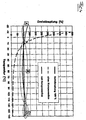
- Fig. 4 the qualitative course of the rotary damping is to be taken as the temperature.
- the dashed line shows approximately hyperbolic progression for the uncompensated case.
- the solid line shows the course with compensation, which can be divided into three temperature ranges A, B and C.
- the area B is determined primarily by the approximately linearly decreasing temperature of the connection channel (13) (variable throttle). At approx. 20 ° C and at approx. 95 ° C, it is possible to ideally compensate for the influence of the changing viscosity. In the temperature range in between there is a good approximation to the ideal course.
- region A the overpressure valves (18) and bypasses not described in detail in section C determine the course of the rotational damping above the temperature.
Landscapes
- Engineering & Computer Science (AREA)
- General Engineering & Computer Science (AREA)
- Physics & Mathematics (AREA)
- Acoustics & Sound (AREA)
- Aviation & Aerospace Engineering (AREA)
- Mechanical Engineering (AREA)
- Combined Devices Of Dampers And Springs (AREA)
Claims (19)
- Dispositif d'accouplement élastique en torsion (1) comprenant au moins deux ressorts de torsion flexibles (3, 4) reliés l'un à l'autre, dans lesquels au moins un ressort de torsion flexible (3, 4) de forme hélicoïdale est agencé concentriquement autour d'un axe de rotation, de sorte qu'un arbre menant un arbre mené peuvent être respectivement amenés en liaison d'action avec les ressorts de torsion flexibles (3, 4) et susceptibles d'être tournés l'un par rapport à l'autre autour de l'axe de rotation à l'encontre d'un couple de rotation de rappel des ressorts de torsion flexibles (3, 4), et comprenant un dispositif d'amortissement (8), caractérisé en ce que le dispositif d'amortissement (8) comprend au moins deux chambres à fluide (9) en communication l'une avec l'autre via un dispositif à étranglement (10) et susceptible d'être remplies avec un fluide d'amortissement, et en ce que le dispositif à étranglement (10) comprend au moins un canal de liaison (13) qui relie lesdites au moins deux chambres à fluide (9) et dont la surface de section transversale traversée par l'écoulement de fluide est modifiable.
- Dispositif d'accouplement élastique en torsion selon la revendication 1, caractérisé en ce qu'il comprend dans le canal de liaison (13) un élément obturateur (14) déplaçable radialement entre une position d'obturation qui obture le canal de liaison (13) et une position passante qui ouvre le canal de liaison (13).
- Dispositif d'accouplement élastique en torsion selon la revendication 2, caractérisé en ce que l'élément obturateur (14) est déplaçable à l'encontre de la force de rappel d'un moyen à ressort.
- Dispositif d'accouplement élastique en torsion selon la revendication 3, caractérisé en ce que la force de rappel du moyen à ressort est dirigée radialement et est imposée en fonction de la masse de l'élément obturateur (14) de telle façon que l'élément obturateur (14) se déplace de la position d'obturation vers la position passante pour une vitesse de rotation prédéterminée du dispositif d'accouplement élastique en torsion (1).
- Dispositif d'accouplement élastique en torsion selon la revendication 3 ou 4, caractérisé en ce que le moyen à ressort soutien l'élément obturateur (14) en direction radiale contre une surface de butée.
- Dispositif d'accouplement élastique en torsion selon l'une des revendications 2 à 5, caractérisé en ce que des évidements et/ou des canaux de by-pass, susceptibles d'être traversés par le fluide, sont agencés dans la région autour de l'élément obturateur déplaçable (14).
- Dispositif d'accouplement élastique en torsion selon l'une des revendications précédentes, caractérisé en ce que le dispositif d'amortissement (8) comprend au moins une valve de surpression (18).
- Dispositif d'accouplement élastique en torsion selon la revendication 7, caractérisé en ce que ladite au moins une valve de surpression (18) comprend un corps de valve (19) déplaçable à l'encontre d'une force de rappel d'un moyen à ressort (20) de la valve de surpression.
- Dispositif d'accouplement élastique en torsion selon l'une des revendications précédentes, caractérisé en ce que lesdits au moins deux ressorts de torsion flexibles (3, 4) sont reliés l'un à l'autre de manière à agir en parallèle.
- Dispositif d'accouplement élastique en torsion selon l'une des revendications précédentes, caractérisé en ce que lesdits au moins deux ressorts de torsion flexibles (3, 4) sont agencés concentriquement à l'axe de rotation et sensiblement dans un plan perpendiculaire à l'axe de rotation.
- Dispositif d'accouplement élastique en torsion selon l'une des revendications précédentes, caractérisé en ce qu'à chaque ressort de torsion flexible (3, 4) sont associés des moyens de guidage qui, lors d'un élargissement ou d'une contraction, imposent un agencement concentrique des ressorts de torsion flexibles.
- Dispositif d'accouplement élastique en torsion selon l'une des revendications précédentes, caractérisé en ce que le dispositif d'amortissement (8) est agencé radialement à distance desdits au moins deux ressorts de torsion flexibles (3, 4).
- Dispositif d'accouplement élastique en torsion selon l'une des revendications précédentes, caractérisé en ce que les chambres à fluide (9) sont remplies uniquement partiellement avec un fluide d'amortissement liquide.
- Dispositif d'accouplement élastique en torsion selon l'une des revendications précédentes, caractérisé en ce qu'une huile au polyglycol est utilisée à titre de fluide d'amortissement.
- Dispositif d'accouplement élastique en torsion selon l'une des revendications précédentes, caractérisé en ce que le dispositif à étranglement (10) dans le canal de liaison (13) comprend un élément d'étranglement (21) modifiable quant à sa forme.
- Dispositif d'accouplement élastique en torsion selon la revendication 15, caractérisé en ce que l'élément d'étranglement (21) est déplaçable, et une paroi extérieure de l'élément d'étranglement (21) forme au moins localement la paroi latérale du canal de liaison (13) qui limite la surface de section transversale du canal de liaison (13) susceptible d'être traversée par l'écoulement de fluide.
- Dispositif d'accouplement élastique en torsion selon la revendication 15 ou 16, caractérisé en ce qu'au moins un corps extensible (22) est agencé dans une chambre intérieure de l'élément d'étranglement (21).
- Dispositif d'accouplement élastique en torsion selon la revendication 17, caractérisé en ce que le corps extensible (22) se dilate lorsque la température augmente, et en raison d'une déformation ou d'un déplacement consécutif de la paroi extérieure, la surface de section transversale susceptible d'être traversée par l'écoulement du fluide du canal de liaison (13) diminue.
- Dispositif d'accouplement élastique en torsion selon la revendication 18, caractérisé en ce que la dilatation due à la température du corps extensible (22) est adaptée à la variation due à la température de la viscosité du fluide d'amortissement.
Priority Applications (1)
| Application Number | Priority Date | Filing Date | Title |
|---|---|---|---|
| EP08012916.6A EP2146111B1 (fr) | 2008-07-17 | 2008-07-17 | Dispositif d'embrayage élastique rotatif |
Applications Claiming Priority (1)
| Application Number | Priority Date | Filing Date | Title |
|---|---|---|---|
| EP08012916.6A EP2146111B1 (fr) | 2008-07-17 | 2008-07-17 | Dispositif d'embrayage élastique rotatif |
Publications (2)
| Publication Number | Publication Date |
|---|---|
| EP2146111A1 EP2146111A1 (fr) | 2010-01-20 |
| EP2146111B1 true EP2146111B1 (fr) | 2016-04-06 |
Family
ID=40076587
Family Applications (1)
| Application Number | Title | Priority Date | Filing Date |
|---|---|---|---|
| EP08012916.6A Not-in-force EP2146111B1 (fr) | 2008-07-17 | 2008-07-17 | Dispositif d'embrayage élastique rotatif |
Country Status (1)
| Country | Link |
|---|---|
| EP (1) | EP2146111B1 (fr) |
Families Citing this family (1)
| Publication number | Priority date | Publication date | Assignee | Title |
|---|---|---|---|---|
| DE102011084142A1 (de) * | 2011-10-07 | 2013-04-11 | Bayerische Motoren Werke Aktiengesellschaft | Drehzahladaptive Torsionsschwingungsdämpferanordnung |
Family Cites Families (5)
| Publication number | Priority date | Publication date | Assignee | Title |
|---|---|---|---|---|
| DE19636628C1 (de) | 1996-09-10 | 1998-04-23 | Freudenberg Carl Fa | Freilauf |
| JP2002317647A (ja) * | 2001-04-24 | 2002-10-31 | Nissan Motor Co Ltd | 内燃機関の振動抑制機構 |
| ITTO20010739A1 (it) | 2001-07-26 | 2003-01-26 | Diantel Corp N V | Gruppo di puleggia, particolarmente per un motore a combustione interna. |
| DE102004043136B3 (de) | 2004-09-07 | 2005-08-11 | Carl Freudenberg Kg | Drehfeder, Drehfederersatz und Anordnung von Drehfedersätzen |
| DE102005055034B3 (de) | 2005-09-01 | 2007-02-08 | Muhr Und Bender Kg | Torisionsschwingungsdämpfer oder Dekoppler mit gewickelten Drahtfedern in einer Antriebsscheibe |
-
2008
- 2008-07-17 EP EP08012916.6A patent/EP2146111B1/fr not_active Not-in-force
Also Published As
| Publication number | Publication date |
|---|---|
| EP2146111A1 (fr) | 2010-01-20 |
Similar Documents
| Publication | Publication Date | Title |
|---|---|---|
| EP0304474B1 (fr) | Accouplement elastique | |
| DE3610127C2 (de) | Drehelastische, schwingungsdämpfende Schwungscheibe | |
| DE3721709C2 (de) | Verfahren zur Herstellung einer Einrichtung zur Dämpfung von Drehschwingungen | |
| EP1715216B1 (fr) | Amortisseur de vibrations torsionelles | |
| EP2598776B1 (fr) | Dispositif de changement de vitesse pour une boîte de vitesses | |
| DE102015211891A1 (de) | Frequenzabhängige Dämpfventilanordnung | |
| EP2525115A2 (fr) | Support hydraulique | |
| WO2008106926A1 (fr) | Amortisseur de vibrations de torsion | |
| EP2283247A1 (fr) | Amortisseur de vibrations de torsion | |
| DE19626729C2 (de) | Rotierende drehschwingungsdämpfende Kraftübertragungseinrichtung | |
| DE10035026A1 (de) | Hydraulisch dämpfendes Elastomerlager | |
| EP2146111B1 (fr) | Dispositif d'embrayage élastique rotatif | |
| EP1584838B1 (fr) | Amortisseur de vibrations de torsion | |
| DE102008017626B4 (de) | Drehfeder mit einer konzentrischen schraubenförmigen Feder | |
| WO2017125221A1 (fr) | Ensemble d'amortissement de vibrations de torsion pour transmission de véhicule | |
| DE102009024564A1 (de) | Vorrichtung zur Übertragung von Drehmomenten | |
| DE102014203179A1 (de) | Drehschwingungsdämpfer | |
| DE19917014B4 (de) | Schwingungsdämpfer | |
| EP2282077B1 (fr) | Dispositif d'amortissement et embrayage élastique rotatif en étant équipé | |
| EP1698798A1 (fr) | Amortisseur de vibrations torsionelles | |
| DE10241103B4 (de) | Elastische Kupplung, insbesondere Zweimassenschwungrad für eine Brennkraftmaschine | |
| DE102017127215A1 (de) | Kupplungsscheibe mit einer Rotationsachse | |
| EP3601843B1 (fr) | Dispositif d'amortissement pour une chaîne cinématique d'un véhicule automobile, en particulier d'un véhicule à moteur, et chaîne cinématique comprenant un tel dispositif d'amortissement | |
| DE19822540A1 (de) | Vorrichtung zum Dämpfen von Schwingungen, insbesondere Schwingungstilger | |
| DE102020116574A1 (de) | Drehschwingungsdämpfer mit hydraulischem Dämpfer |
Legal Events
| Date | Code | Title | Description |
|---|---|---|---|
| PUAI | Public reference made under article 153(3) epc to a published international application that has entered the european phase |
Free format text: ORIGINAL CODE: 0009012 |
|
| 17P | Request for examination filed |
Effective date: 20090806 |
|
| AK | Designated contracting states |
Kind code of ref document: A1 Designated state(s): AT BE BG CH CY CZ DE DK EE ES FI FR GB GR HR HU IE IS IT LI LT LU LV MC MT NL NO PL PT RO SE SI SK TR |
|
| AX | Request for extension of the european patent |
Extension state: AL BA MK RS |
|
| AKX | Designation fees paid |
Designated state(s): AT BE BG CH CY CZ DE DK EE ES FI FR GB GR HR HU IE IS IT LI LT LU LV MC MT NL NO PL PT RO SE SI SK TR |
|
| GRAP | Despatch of communication of intention to grant a patent |
Free format text: ORIGINAL CODE: EPIDOSNIGR1 |
|
| INTG | Intention to grant announced |
Effective date: 20151006 |
|
| RAP1 | Party data changed (applicant data changed or rights of an application transferred) |
Owner name: TRELLEBORGVIBRACOUSTIC GMBH |
|
| GRAS | Grant fee paid |
Free format text: ORIGINAL CODE: EPIDOSNIGR3 |
|
| GRAA | (expected) grant |
Free format text: ORIGINAL CODE: 0009210 |
|
| AK | Designated contracting states |
Kind code of ref document: B1 Designated state(s): AT BE BG CH CY CZ DE DK EE ES FI FR GB GR HR HU IE IS IT LI LT LU LV MC MT NL NO PL PT RO SE SI SK TR |
|
| REG | Reference to a national code |
Ref country code: GB Ref legal event code: FG4D Free format text: NOT ENGLISH |
|
| REG | Reference to a national code |
Ref country code: AT Ref legal event code: REF Ref document number: 788176 Country of ref document: AT Kind code of ref document: T Effective date: 20160415 Ref country code: CH Ref legal event code: EP |
|
| REG | Reference to a national code |
Ref country code: IE Ref legal event code: FG4D Free format text: LANGUAGE OF EP DOCUMENT: GERMAN |
|
| REG | Reference to a national code |
Ref country code: DE Ref legal event code: R096 Ref document number: 502008014033 Country of ref document: DE |
|
| REG | Reference to a national code |
Ref country code: FR Ref legal event code: PLFP Year of fee payment: 9 |
|
| REG | Reference to a national code |
Ref country code: LT Ref legal event code: MG4D Ref country code: NL Ref legal event code: MP Effective date: 20160406 |
|
| PG25 | Lapsed in a contracting state [announced via postgrant information from national office to epo] |
Ref country code: NL Free format text: LAPSE BECAUSE OF FAILURE TO SUBMIT A TRANSLATION OF THE DESCRIPTION OR TO PAY THE FEE WITHIN THE PRESCRIBED TIME-LIMIT Effective date: 20160406 |
|
| PG25 | Lapsed in a contracting state [announced via postgrant information from national office to epo] |
Ref country code: PL Free format text: LAPSE BECAUSE OF FAILURE TO SUBMIT A TRANSLATION OF THE DESCRIPTION OR TO PAY THE FEE WITHIN THE PRESCRIBED TIME-LIMIT Effective date: 20160406 Ref country code: FI Free format text: LAPSE BECAUSE OF FAILURE TO SUBMIT A TRANSLATION OF THE DESCRIPTION OR TO PAY THE FEE WITHIN THE PRESCRIBED TIME-LIMIT Effective date: 20160406 Ref country code: IS Free format text: LAPSE BECAUSE OF FAILURE TO SUBMIT A TRANSLATION OF THE DESCRIPTION OR TO PAY THE FEE WITHIN THE PRESCRIBED TIME-LIMIT Effective date: 20160806 Ref country code: LT Free format text: LAPSE BECAUSE OF FAILURE TO SUBMIT A TRANSLATION OF THE DESCRIPTION OR TO PAY THE FEE WITHIN THE PRESCRIBED TIME-LIMIT Effective date: 20160406 Ref country code: NO Free format text: LAPSE BECAUSE OF FAILURE TO SUBMIT A TRANSLATION OF THE DESCRIPTION OR TO PAY THE FEE WITHIN THE PRESCRIBED TIME-LIMIT Effective date: 20160706 |
|
| PG25 | Lapsed in a contracting state [announced via postgrant information from national office to epo] |
Ref country code: ES Free format text: LAPSE BECAUSE OF FAILURE TO SUBMIT A TRANSLATION OF THE DESCRIPTION OR TO PAY THE FEE WITHIN THE PRESCRIBED TIME-LIMIT Effective date: 20160406 Ref country code: GR Free format text: LAPSE BECAUSE OF FAILURE TO SUBMIT A TRANSLATION OF THE DESCRIPTION OR TO PAY THE FEE WITHIN THE PRESCRIBED TIME-LIMIT Effective date: 20160707 Ref country code: LV Free format text: LAPSE BECAUSE OF FAILURE TO SUBMIT A TRANSLATION OF THE DESCRIPTION OR TO PAY THE FEE WITHIN THE PRESCRIBED TIME-LIMIT Effective date: 20160406 Ref country code: HR Free format text: LAPSE BECAUSE OF FAILURE TO SUBMIT A TRANSLATION OF THE DESCRIPTION OR TO PAY THE FEE WITHIN THE PRESCRIBED TIME-LIMIT Effective date: 20160406 Ref country code: PT Free format text: LAPSE BECAUSE OF FAILURE TO SUBMIT A TRANSLATION OF THE DESCRIPTION OR TO PAY THE FEE WITHIN THE PRESCRIBED TIME-LIMIT Effective date: 20160808 Ref country code: SE Free format text: LAPSE BECAUSE OF FAILURE TO SUBMIT A TRANSLATION OF THE DESCRIPTION OR TO PAY THE FEE WITHIN THE PRESCRIBED TIME-LIMIT Effective date: 20160406 |
|
| PG25 | Lapsed in a contracting state [announced via postgrant information from national office to epo] |
Ref country code: IT Free format text: LAPSE BECAUSE OF FAILURE TO SUBMIT A TRANSLATION OF THE DESCRIPTION OR TO PAY THE FEE WITHIN THE PRESCRIBED TIME-LIMIT Effective date: 20160406 Ref country code: BE Free format text: LAPSE BECAUSE OF NON-PAYMENT OF DUE FEES Effective date: 20160731 |
|
| REG | Reference to a national code |
Ref country code: DE Ref legal event code: R097 Ref document number: 502008014033 Country of ref document: DE |
|
| PG25 | Lapsed in a contracting state [announced via postgrant information from national office to epo] |
Ref country code: RO Free format text: LAPSE BECAUSE OF FAILURE TO SUBMIT A TRANSLATION OF THE DESCRIPTION OR TO PAY THE FEE WITHIN THE PRESCRIBED TIME-LIMIT Effective date: 20160406 Ref country code: SK Free format text: LAPSE BECAUSE OF FAILURE TO SUBMIT A TRANSLATION OF THE DESCRIPTION OR TO PAY THE FEE WITHIN THE PRESCRIBED TIME-LIMIT Effective date: 20160406 Ref country code: EE Free format text: LAPSE BECAUSE OF FAILURE TO SUBMIT A TRANSLATION OF THE DESCRIPTION OR TO PAY THE FEE WITHIN THE PRESCRIBED TIME-LIMIT Effective date: 20160406 Ref country code: CZ Free format text: LAPSE BECAUSE OF FAILURE TO SUBMIT A TRANSLATION OF THE DESCRIPTION OR TO PAY THE FEE WITHIN THE PRESCRIBED TIME-LIMIT Effective date: 20160406 Ref country code: DK Free format text: LAPSE BECAUSE OF FAILURE TO SUBMIT A TRANSLATION OF THE DESCRIPTION OR TO PAY THE FEE WITHIN THE PRESCRIBED TIME-LIMIT Effective date: 20160406 |
|
| PLBE | No opposition filed within time limit |
Free format text: ORIGINAL CODE: 0009261 |
|
| STAA | Information on the status of an ep patent application or granted ep patent |
Free format text: STATUS: NO OPPOSITION FILED WITHIN TIME LIMIT |
|
| REG | Reference to a national code |
Ref country code: CH Ref legal event code: PL |
|
| 26N | No opposition filed |
Effective date: 20170110 |
|
| GBPC | Gb: european patent ceased through non-payment of renewal fee |
Effective date: 20160717 |
|
| PG25 | Lapsed in a contracting state [announced via postgrant information from national office to epo] |
Ref country code: MC Free format text: LAPSE BECAUSE OF FAILURE TO SUBMIT A TRANSLATION OF THE DESCRIPTION OR TO PAY THE FEE WITHIN THE PRESCRIBED TIME-LIMIT Effective date: 20160406 |
|
| PG25 | Lapsed in a contracting state [announced via postgrant information from national office to epo] |
Ref country code: LI Free format text: LAPSE BECAUSE OF NON-PAYMENT OF DUE FEES Effective date: 20160731 Ref country code: CH Free format text: LAPSE BECAUSE OF NON-PAYMENT OF DUE FEES Effective date: 20160731 |
|
| REG | Reference to a national code |
Ref country code: IE Ref legal event code: MM4A |
|
| PG25 | Lapsed in a contracting state [announced via postgrant information from national office to epo] |
Ref country code: SI Free format text: LAPSE BECAUSE OF FAILURE TO SUBMIT A TRANSLATION OF THE DESCRIPTION OR TO PAY THE FEE WITHIN THE PRESCRIBED TIME-LIMIT Effective date: 20160406 Ref country code: GB Free format text: LAPSE BECAUSE OF NON-PAYMENT OF DUE FEES Effective date: 20160717 |
|
| REG | Reference to a national code |
Ref country code: FR Ref legal event code: PLFP Year of fee payment: 10 |
|
| PG25 | Lapsed in a contracting state [announced via postgrant information from national office to epo] |
Ref country code: IE Free format text: LAPSE BECAUSE OF NON-PAYMENT OF DUE FEES Effective date: 20160717 |
|
| PG25 | Lapsed in a contracting state [announced via postgrant information from national office to epo] |
Ref country code: LU Free format text: LAPSE BECAUSE OF NON-PAYMENT OF DUE FEES Effective date: 20160717 |
|
| REG | Reference to a national code |
Ref country code: AT Ref legal event code: MM01 Ref document number: 788176 Country of ref document: AT Kind code of ref document: T Effective date: 20160717 |
|
| PG25 | Lapsed in a contracting state [announced via postgrant information from national office to epo] |
Ref country code: AT Free format text: LAPSE BECAUSE OF NON-PAYMENT OF DUE FEES Effective date: 20160717 |
|
| PG25 | Lapsed in a contracting state [announced via postgrant information from national office to epo] |
Ref country code: CY Free format text: LAPSE BECAUSE OF FAILURE TO SUBMIT A TRANSLATION OF THE DESCRIPTION OR TO PAY THE FEE WITHIN THE PRESCRIBED TIME-LIMIT Effective date: 20160406 Ref country code: HU Free format text: LAPSE BECAUSE OF FAILURE TO SUBMIT A TRANSLATION OF THE DESCRIPTION OR TO PAY THE FEE WITHIN THE PRESCRIBED TIME-LIMIT; INVALID AB INITIO Effective date: 20080717 |
|
| PG25 | Lapsed in a contracting state [announced via postgrant information from national office to epo] |
Ref country code: TR Free format text: LAPSE BECAUSE OF FAILURE TO SUBMIT A TRANSLATION OF THE DESCRIPTION OR TO PAY THE FEE WITHIN THE PRESCRIBED TIME-LIMIT Effective date: 20160406 Ref country code: MT Free format text: LAPSE BECAUSE OF FAILURE TO SUBMIT A TRANSLATION OF THE DESCRIPTION OR TO PAY THE FEE WITHIN THE PRESCRIBED TIME-LIMIT Effective date: 20160406 |
|
| REG | Reference to a national code |
Ref country code: FR Ref legal event code: PLFP Year of fee payment: 11 |
|
| PG25 | Lapsed in a contracting state [announced via postgrant information from national office to epo] |
Ref country code: BG Free format text: LAPSE BECAUSE OF FAILURE TO SUBMIT A TRANSLATION OF THE DESCRIPTION OR TO PAY THE FEE WITHIN THE PRESCRIBED TIME-LIMIT Effective date: 20160406 |
|
| PGFP | Annual fee paid to national office [announced via postgrant information from national office to epo] |
Ref country code: FR Payment date: 20180723 Year of fee payment: 11 Ref country code: DE Payment date: 20180829 Year of fee payment: 11 |
|
| REG | Reference to a national code |
Ref country code: DE Ref legal event code: R119 Ref document number: 502008014033 Country of ref document: DE |
|
| PG25 | Lapsed in a contracting state [announced via postgrant information from national office to epo] |
Ref country code: DE Free format text: LAPSE BECAUSE OF NON-PAYMENT OF DUE FEES Effective date: 20200201 |
|
| PG25 | Lapsed in a contracting state [announced via postgrant information from national office to epo] |
Ref country code: FR Free format text: LAPSE BECAUSE OF NON-PAYMENT OF DUE FEES Effective date: 20190731 |